EP0063463A2 - Lockable control lever arrangement - Google Patents
Lockable control lever arrangement Download PDFInfo
- Publication number
- EP0063463A2 EP0063463A2 EP19820301901 EP82301901A EP0063463A2 EP 0063463 A2 EP0063463 A2 EP 0063463A2 EP 19820301901 EP19820301901 EP 19820301901 EP 82301901 A EP82301901 A EP 82301901A EP 0063463 A2 EP0063463 A2 EP 0063463A2
- Authority
- EP
- European Patent Office
- Prior art keywords
- locking
- control lever
- arrangement according
- lockable
- lever arrangement
- Prior art date
- Legal status (The legal status is an assumption and is not a legal conclusion. Google has not performed a legal analysis and makes no representation as to the accuracy of the status listed.)
- Granted
Links
Images


Classifications
-
- G—PHYSICS
- G05—CONTROLLING; REGULATING
- G05G—CONTROL DEVICES OR SYSTEMS INSOFAR AS CHARACTERISED BY MECHANICAL FEATURES ONLY
- G05G9/00—Manually-actuated control mechanisms provided with one single controlling member co-operating with two or more controlled members, e.g. selectively, simultaneously
- G05G9/02—Manually-actuated control mechanisms provided with one single controlling member co-operating with two or more controlled members, e.g. selectively, simultaneously the controlling member being movable in different independent ways, movement in each individual way actuating one controlled member only
- G05G9/04—Manually-actuated control mechanisms provided with one single controlling member co-operating with two or more controlled members, e.g. selectively, simultaneously the controlling member being movable in different independent ways, movement in each individual way actuating one controlled member only in which movement in two or more ways can occur simultaneously
- G05G9/047—Manually-actuated control mechanisms provided with one single controlling member co-operating with two or more controlled members, e.g. selectively, simultaneously the controlling member being movable in different independent ways, movement in each individual way actuating one controlled member only in which movement in two or more ways can occur simultaneously the controlling member being movable by hand about orthogonal axes, e.g. joysticks
-
- E—FIXED CONSTRUCTIONS
- E02—HYDRAULIC ENGINEERING; FOUNDATIONS; SOIL SHIFTING
- E02F—DREDGING; SOIL-SHIFTING
- E02F9/00—Component parts of dredgers or soil-shifting machines, not restricted to one of the kinds covered by groups E02F3/00 - E02F7/00
- E02F9/20—Drives; Control devices
- E02F9/2004—Control mechanisms, e.g. control levers
-
- E—FIXED CONSTRUCTIONS
- E02—HYDRAULIC ENGINEERING; FOUNDATIONS; SOIL SHIFTING
- E02F—DREDGING; SOIL-SHIFTING
- E02F9/00—Component parts of dredgers or soil-shifting machines, not restricted to one of the kinds covered by groups E02F3/00 - E02F7/00
- E02F9/24—Safety devices, e.g. for preventing overload
-
- G—PHYSICS
- G05—CONTROLLING; REGULATING
- G05G—CONTROL DEVICES OR SYSTEMS INSOFAR AS CHARACTERISED BY MECHANICAL FEATURES ONLY
- G05G5/00—Means for preventing, limiting or returning the movements of parts of a control mechanism, e.g. locking controlling member
- G05G5/005—Means for preventing, limiting or returning the movements of parts of a control mechanism, e.g. locking controlling member for preventing unintentional use of a control mechanism
-
- G—PHYSICS
- G05—CONTROLLING; REGULATING
- G05G—CONTROL DEVICES OR SYSTEMS INSOFAR AS CHARACTERISED BY MECHANICAL FEATURES ONLY
- G05G9/00—Manually-actuated control mechanisms provided with one single controlling member co-operating with two or more controlled members, e.g. selectively, simultaneously
- G05G9/02—Manually-actuated control mechanisms provided with one single controlling member co-operating with two or more controlled members, e.g. selectively, simultaneously the controlling member being movable in different independent ways, movement in each individual way actuating one controlled member only
- G05G9/04—Manually-actuated control mechanisms provided with one single controlling member co-operating with two or more controlled members, e.g. selectively, simultaneously the controlling member being movable in different independent ways, movement in each individual way actuating one controlled member only in which movement in two or more ways can occur simultaneously
- G05G9/047—Manually-actuated control mechanisms provided with one single controlling member co-operating with two or more controlled members, e.g. selectively, simultaneously the controlling member being movable in different independent ways, movement in each individual way actuating one controlled member only in which movement in two or more ways can occur simultaneously the controlling member being movable by hand about orthogonal axes, e.g. joysticks
- G05G2009/04703—Mounting of controlling member
- G05G2009/04714—Mounting of controlling member with orthogonal axes
- G05G2009/04718—Mounting of controlling member with orthogonal axes with cardan or gimbal type joint
-
- Y—GENERAL TAGGING OF NEW TECHNOLOGICAL DEVELOPMENTS; GENERAL TAGGING OF CROSS-SECTIONAL TECHNOLOGIES SPANNING OVER SEVERAL SECTIONS OF THE IPC; TECHNICAL SUBJECTS COVERED BY FORMER USPC CROSS-REFERENCE ART COLLECTIONS [XRACs] AND DIGESTS
- Y10—TECHNICAL SUBJECTS COVERED BY FORMER USPC
- Y10T—TECHNICAL SUBJECTS COVERED BY FORMER US CLASSIFICATION
- Y10T137/00—Fluid handling
- Y10T137/8593—Systems
- Y10T137/87056—With selective motion for plural valve actuator
- Y10T137/87072—Rotation about either of two pivotal axes
-
- Y—GENERAL TAGGING OF NEW TECHNOLOGICAL DEVELOPMENTS; GENERAL TAGGING OF CROSS-SECTIONAL TECHNOLOGIES SPANNING OVER SEVERAL SECTIONS OF THE IPC; TECHNICAL SUBJECTS COVERED BY FORMER USPC CROSS-REFERENCE ART COLLECTIONS [XRACs] AND DIGESTS
- Y10—TECHNICAL SUBJECTS COVERED BY FORMER USPC
- Y10T—TECHNICAL SUBJECTS COVERED BY FORMER US CLASSIFICATION
- Y10T74/00—Machine element or mechanism
- Y10T74/20—Control lever and linkage systems
- Y10T74/20012—Multiple controlled elements
- Y10T74/20201—Control moves in two planes
-
- Y—GENERAL TAGGING OF NEW TECHNOLOGICAL DEVELOPMENTS; GENERAL TAGGING OF CROSS-SECTIONAL TECHNOLOGIES SPANNING OVER SEVERAL SECTIONS OF THE IPC; TECHNICAL SUBJECTS COVERED BY FORMER USPC CROSS-REFERENCE ART COLLECTIONS [XRACs] AND DIGESTS
- Y10—TECHNICAL SUBJECTS COVERED BY FORMER USPC
- Y10T—TECHNICAL SUBJECTS COVERED BY FORMER US CLASSIFICATION
- Y10T74/00—Machine element or mechanism
- Y10T74/20—Control lever and linkage systems
- Y10T74/20207—Multiple controlling elements for single controlled element
- Y10T74/20238—Interlocked
-
- Y—GENERAL TAGGING OF NEW TECHNOLOGICAL DEVELOPMENTS; GENERAL TAGGING OF CROSS-SECTIONAL TECHNOLOGIES SPANNING OVER SEVERAL SECTIONS OF THE IPC; TECHNICAL SUBJECTS COVERED BY FORMER USPC CROSS-REFERENCE ART COLLECTIONS [XRACs] AND DIGESTS
- Y10—TECHNICAL SUBJECTS COVERED BY FORMER USPC
- Y10T—TECHNICAL SUBJECTS COVERED BY FORMER US CLASSIFICATION
- Y10T74/00—Machine element or mechanism
- Y10T74/20—Control lever and linkage systems
- Y10T74/20576—Elements
- Y10T74/20636—Detents
- Y10T74/20648—Interrelated lever release
Definitions
- This invention relates to control lever arrangements and particularly, though not exclusively, to such arrangements for the control of hydraulic valves on industrial or agricultural tractors and the like.
- a lockable control lever arrangement comprising a pivotally mounted control lever; linkage means for connecting the control lever with a function to be controlled; and a locking device for locking the lever in a given position, the arrangement being characterised in that the locking device comprises a first locking formation operatively connected with the linkage means, a locking member having a second locking formation engageable with the first locking formation to lock the control lever in said given position, and a manually operable operating means for moving the locking member to bring the first and second formations into engagement to effect said locking.
- the present invention is particularly applicable to control lever arrangements for the control of one or more hydraulic valves.
- control lever arrangements employed to operate the hydraulic valves which control loaders and diggers of industrial tractors.
- the locking device may be arranged to lock the or each associated control valve in its neutral position thus preventing operation of the loader or digger.
- this is a safety device to prevent accidental operation of the loader and digger and if associated with, for example, a key operated lock, could also be used as a security device to prevent unauthorised use of the loader or digger.
- part of the linkage means moves in a first direction and the locking member pivots in a plane generally perpendicular to said first direction about an axis generally parallel to said first direction to engage the first locking formation carried by said part of the linkage means.
- the first locking formation may comprise a disc mounted on said part of the linkage means and the second locking formation may comprise an arm with a cut-out shaped to receive part of the outer peripheral portion of the disc to prevent movement of said part of the linkage means in said first direction when the arm is pivotted about said generally parallel axis into engagement with the disc.
- the control lever may be pivotable about two perpendicular axes to control two functions via separate linkage means in, for example, the manner described in the Applicants co-pending Application No. 8101477.
- each linkage means would be provided with a first locking formation and the locking member would be provided with two second locking formations for engagement with said respective first locking formations.
- the or each linkage means includes a generally vertically movable operating member which carries the first locking formation and the locking member pivots in a generally horizontal plane to engage the or each first locking formation.
- control lever is supported on a generally vertically extending stand, part of the stand carrying the locking member for pivotal movement in a generally horizontal plane.
- the control lever arrangement may include a second pivotally mounted control lever which is also provided with a further locking device having first and second interengageable locking formations, said further locking device also being operated by said manually operable operating means.
- the present invention also provides a loader or digger controlled by a number of fluid pressure control valves operated by a lockable control lever arrangement of the form described above.
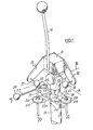
- Figure 1 shows a control lever arrangement in which a lever 10 is welded to a block 11 which supports two arms 12 and 13. The block is supported via a universal joint 14 on a stand 15.
- the universal joint 14 permits pivotting of the lever 10 about a first axis A and about a second intersecting axis B at right angles thereto.
- the arms 12 and 13 are connected via ball joints 16 and 17 respectively with valve operating rods 18 and 19.
- Ball joint 16 lies on axis A while ball joint 17 lies on axis B.
- pivotting of lever 10 about axis A causes rod 19 to move vertically as indicated by arrow D to operate an associate control valve spool.
- No movement of rod 18 occurs during simple pivotting of lever 10 about axle A since ball joint 16 lies on axis A.
- pivotting of lever 10 about axis B moves rod 18 and the associated valve spool, as indicated by arrow E, without movement of rod 19 since ball joint 17 lies on axis B.
- Valve rods 18 and 19 can be moved simultaneously by pivotting lever 10 about a diagonal axis lying between axis A and B.
- a locking device (60) is provided for the control lever.
- the locking device comprises a locking memberlin the form of a collar 20 which is pivotally mounted on stand 15 and has two arms 21 and 22 each having locking formations in the form of 21a,22a.
- the locking device also includes further locking formations in the form of discs 23 and 24 which are engageable by cut-outs 21a,22a and are mounted on valve rods 18 and 19 by nuts 25 and 26, which engage screw-threaded portions of the rods. Washers may conveniently be used to provide discs 23 and 24.
- valves controlled by lever 10 are both biassed to their neutral (closed) position so that when the lever 10 is released it returns to its upright neutral position.
- the cut-outs 21a and 22a are arranged to only be engageable with discs 23 and 24 when the lever is in its neutral position.
- the half-depth X of each are 21,22 can be arranged to be greater than the travel of each rod from its neutral position so that each disc 23,24 cannot move to a location above or below the associated arm so that the control lever and associated valves can only be locked in their neutral postions.
- FIG. 1 An operating means for the locking member 20,21,22 is shown diagrammatically in Figure 1 in the form of an arm 126 which is welded to the sleeve 20 and a push-pull rod 27 which is pivotted to the arm 126 at 28.
- the locking member can be moved from the locked position shown in Figure 1 by pulling handle 29 associated with rod 27 in the direction of the arrow Z of Figure 1.
- This movement of handle 29 rotates the sleeve 20 and the arms 21 and 22 in the direction of arrow F through an angle of approximately 45% thus disenganging the discs 23 and 24 and allowing the control lever 10 to be moved.
- the control lever is locked by reversing the above movement of handle 29 to re-engage the cut-outs 21a and 22a with the discs 23 and 24 respectively.
- control lever 10 is used to control, for example, a front loader on an industrial tractor
- rod 18 could be used to operate a hydraulic valve which controls the rolling- back and emptying of the loader bucket while rod 19 could be used to operate a hydraulic valve which control the raising and lowering of the loader beams.
- FIG 2 shows a twin lever control arrangement of the form shown in Figure 1 of the Applicants previously referred to co-pending application No. 810477 modified to include a locking device in accordance with the present invention.
- the construction and arrangement of the control lever 10 shown in Figure 2 is generally the same as that previously described in relation to Figure 1 and corresponding elements have therefore been similarly numbered.
- a second control lever 40 is provided which is mounted on a universal joint 41 for pivotting about an axis C (which is co-axial with axis A) and an axis D (which is parallel to axis B).
- Lever 40 is carried by a block 42 which in turn carries an arm 43.
- Arm 43 is connected via ball joint 44 with a vlave operating rod 45.
- this valve operating rod controls a valve which opens and closes a 4 in 1 bucket of the loader.
- Figure 2 diagrammatically illustrates a block 70 of spool valves whose spools 18a,19a and 45a are connected to control rods 18,19 and 45 respectively.
- the ball joint 41 is mounted on an arm 46 which is attached to the stand 15.
- the two control levers 10 and 40 are inter-connected via a link 47 which is pivotally connected via ball joints 48 and 49 with the two levers 10 and 40.
- lever 10 pivotting of lever 10 about axis B operates control rod 18 without operating control rods 19 and 45, although lever 40 will also pivot about axis D due to the presence of the connecting link 47.
- Pivottisg of lever 10 about axis A causes operation of control rod 19 without operation of control rods 18 and 45.
- Pivotting of control lever 40 about axis C causes operation of control rod 45 without operation of control rods 18 and 19, and pivotting of control lever 40 about axis D causes operation of control rod 18 via link 47 without operation of control rods 19 and 45.
- control levers 10 and 40 If the reader requires further description of the operation and construction of control levers 10 and 40 reference should be made to the Applicant's previously referred to co-pending application No. 810477.
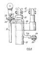
- Figures 3 and 4 show parts of the control lever arrangement of Figure 2 on a larger scale.
- the collar 20 is moved by an arm 126 which is of Z-shape.
- the end 30 of rod 126 which is welded to collar 20 at 30a is arranged to abutt disc 23 when the control lever 10 is locked thus providing and end stop for the movement of the rod 27.
- the unlocked positions of arms 21 and 22 are shown in dotted detail at 21' and 22' in Figure 3.
- Figure 3 also shows a sheet metal casing which surrounds the lower portion of the control lever arrangement below the universal joints.
- control levers are spring biassed to their neutral positions so that the discs 23,24 etc. automatically come into registry with the cut-outs 21a,22a etc. when the levers are released it is possible to shape the arms 21 and 22 so they automatically cam the discs into registry with the cut-outs 21a and 22a if spring loading to their neutral positions is not employed.
- Figure 5 diagrammatically illustrates a shaped arm 21 which on pivotting in the direction of the arrow Y of Figure 5 will automatically cam any associated disc into its cut-out 21a.
- the present invention thus provides a simple and yet efficient lockable control lever arrangement which is particularly suitable for the control of one or more hydraulic valves used to control, for example, loaders and diggers of industrial tractors.
Abstract
Description
- This invention relates to control lever arrangements and particularly, though not exclusively, to such arrangements for the control of hydraulic valves on industrial or agricultural tractors and the like.
- It is an object of the present invention to provide an improved form of control lever arrangement which includes a safeguard against accidental use.
- Thus according to the present invention there is provided a lockable control lever arrangement comprising a pivotally mounted control lever; linkage means for connecting the control lever with a function to be controlled; and a locking device for locking the lever in a given position, the arrangement being characterised in that the locking device comprises a first locking formation operatively connected with the linkage means, a locking member having a second locking formation engageable with the first locking formation to lock the control lever in said given position, and a manually operable operating means for moving the locking member to bring the first and second formations into engagement to effect said locking.
- The present invention is particularly applicable to control lever arrangements for the control of one or more hydraulic valves. For example, control lever arrangements employed to operate the hydraulic valves which control loaders and diggers of industrial tractors. When used in such an application the locking device may be arranged to lock the or each associated control valve in its neutral position thus preventing operation of the loader or digger. As will be appreciated this is a safety device to prevent accidental operation of the loader and digger and if associated with, for example, a key operated lock, could also be used as a security device to prevent unauthorised use of the loader or digger.
- In a preferred construction part of the linkage means moves in a first direction and the locking member pivots in a plane generally perpendicular to said first direction about an axis generally parallel to said first direction to engage the first locking formation carried by said part of the linkage means.
- Conveniently the first locking formation may comprise a disc mounted on said part of the linkage means and the second locking formation may comprise an arm with a cut-out shaped to receive part of the outer peripheral portion of the disc to prevent movement of said part of the linkage means in said first direction when the arm is pivotted about said generally parallel axis into engagement with the disc.
- The control lever may be pivotable about two perpendicular axes to control two functions via separate linkage means in, for example, the manner described in the Applicants co-pending Application No. 8101477. In such an arrangement each linkage means would be provided with a first locking formation and the locking member would be provided with two second locking formations for engagement with said respective first locking formations.
- Preferably the or each linkage means includes a generally vertically movable operating member which carries the first locking formation and the locking member pivots in a generally horizontal plane to engage the or each first locking formation.
- Preferably the control lever is supported on a generally vertically extending stand, part of the stand carrying the locking member for pivotal movement in a generally horizontal plane.
- The control lever arrangement may include a second pivotally mounted control lever which is also provided with a further locking device having first and second interengageable locking formations, said further locking device also being operated by said manually operable operating means.
- The present invention also provides a loader or digger controlled by a number of fluid pressure control valves operated by a lockable control lever arrangement of the form described above.
- Two embodiments of the present invention will now be described, by way of example only, with reference to the accompanying drawings in which:-
- Figure 1 is a diagrammatic perspective view of a single control lever arrangement embodying the present invention;
- Figure 2 is a side view of a twin control lever arrangement embodying the present invention;
- Figures 3 and 4 are plan and side views respectively of parts of Figure 2 on a larger scale, and
- Figure 5 shows part of a modified form of locking device which includes a cam action.
- Figure 1 shows a control lever arrangement in which a
lever 10 is welded to a block 11 which supports twoarms universal joint 14 on astand 15. - The
universal joint 14 permits pivotting of thelever 10 about a first axis A and about a second intersecting axis B at right angles thereto. Thearms ball joints valve operating rods Ball joint 16 lies on axis A whileball joint 17 lies on axis B. - .1 As will be appreciated pivotting of
lever 10 about axisA causes rod 19 to move vertically as indicated by arrow D to operate an associate control valve spool. No movement ofrod 18 occurs during simple pivotting oflever 10 about axle A sinceball joint 16 lies on axis A. In a similar manner pivotting oflever 10 about axis B movesrod 18 and the associated valve spool, as indicated by arrow E, without movement ofrod 19 sinceball joint 17 lies on axisB. Valve rods lever 10 about a diagonal axis lying between axis A and B. - A locking device (60) is provided for the control lever. The locking device comprises a locking memberlin the form of a
collar 20 which is pivotally mounted onstand 15 and has twoarms discs outs valve rods nuts discs - It will be appreciated that when the locking device is engaged (has shown in Figure 1) the cut-
outs discs control rods - In the arrangement illustrated in Figure 1 the valves controlled by
lever 10 are both biassed to their neutral (closed) position so that when thelever 10 is released it returns to its upright neutral position. The cut-outs discs - As an additional safety feature the half-depth X of each are 21,22 can be arranged to be greater than the travel of each rod from its neutral position so that each
disc - An operating means for the
locking member arm 126 which is welded to thesleeve 20 and a push-pull rod 27 which is pivotted to thearm 126 at 28. Thus the locking member can be moved from the locked position shown in Figure 1 bypulling handle 29 associated withrod 27 in the direction of the arrow Z of Figure 1. This movement ofhandle 29 rotates thesleeve 20 and thearms discs control lever 10 to be moved. The control lever is locked by reversing the above movement ofhandle 29 to re-engage the cut-outs discs - If the
control lever 10 is used to control, for example, a front loader on an industrial tractor,rod 18 could be used to operate a hydraulic valve which controls the rolling- back and emptying of the loader bucket whilerod 19 could be used to operate a hydraulic valve which control the raising and lowering of the loader beams. - Figure 2 shows a twin lever control arrangement of the form shown in Figure 1 of the Applicants previously referred to co-pending application No. 810477 modified to include a locking device in accordance with the present invention. The construction and arrangement of the
control lever 10 shown in Figure 2 is generally the same as that previously described in relation to Figure 1 and corresponding elements have therefore been similarly numbered. - A
second control lever 40 is provided which is mounted on auniversal joint 41 for pivotting about an axis C (which is co-axial with axis A) and an axis D (which is parallel to axis B).Lever 40 is carried by ablock 42 which in turn carries an arm 43. Arm 43 is connected viaball joint 44 with avlave operating rod 45. When the twin control lever arrangement is used on a loader this valve operating rod controls a valve which opens and closes a 4 in 1 bucket of the loader. - Figure 2 diagrammatically illustrates a block 70 of spool valves whose
spools 18a,19a and 45a are connected tocontrol rods - As can be seen the
ball joint 41 is mounted on anarm 46 which is attached to thestand 15. The two control levers 10 and 40 are inter-connected via alink 47 which is pivotally connected viaball joints levers - As will be appreciated pivotting of
lever 10 about axis B operatescontrol rod 18 withoutoperating control rods lever 40 will also pivot about axis D due to the presence of the connectinglink 47. Pivottisg oflever 10 about axis A causes operation ofcontrol rod 19 without operation ofcontrol rods - Pivotting of control lever 40 about axis C causes operation of
control rod 45 without operation ofcontrol rods control lever 40 about axis D causes operation ofcontrol rod 18 vialink 47 without operation ofcontrol rods - If the reader requires further description of the operation and construction of control levers 10 and 40 reference should be made to the Applicant's previously referred to co-pending application No. 810477.
- Figures 3 and 4 show parts of the control lever arrangement of Figure 2 on a larger scale. As can be seen the
collar 20 is moved by anarm 126 which is of Z-shape. Also theend 30 ofrod 126 which is welded to collar 20 at 30a is arranged to abuttdisc 23 when thecontrol lever 10 is locked thus providing and end stop for the movement of therod 27. The unlocked positions ofarms - In Figure 2 no locking device is shown for operation on
control lever 40. However, if desired a collar similar to thecollar 20 used oncontrol lever 10 could be mounted around the reduceddiameter portion 50 provided below theuniversal joint 41. As will be appreciated if a collar is mounted onportion 50 it will only require one arm equivalent to thearm 22 for engagement with a washer mounted oncontrol rod 45. This second collar could be arranged to be operated from the same control handle 29, either by a separate connection with the handle or by connecting the second collar with the first collar so that pivotting of the first collar results in pivotting of the second collar. - Although in the arrangements described above the control levers are spring biassed to their neutral positions so that the
discs outs arms outs - For example, Figure 5 diagrammatically illustrates a shaped
arm 21 which on pivotting in the direction of the arrow Y of Figure 5 will automatically cam any associated disc into its cut-out 21a. - The present invention thus provides a simple and yet efficient lockable control lever arrangement which is particularly suitable for the control of one or more hydraulic valves used to control, for example, loaders and diggers of industrial tractors.
Claims (11)
Applications Claiming Priority (2)
| Application Number | Priority Date | Filing Date | Title |
|---|---|---|---|
| GB8112380 | 1981-04-21 | ||
| GB8112380 | 1981-04-21 |
Publications (3)
| Publication Number | Publication Date |
|---|---|
| EP0063463A2 true EP0063463A2 (en) | 1982-10-27 |
| EP0063463A3 EP0063463A3 (en) | 1983-05-11 |
| EP0063463B1 EP0063463B1 (en) | 1987-08-19 |
Family
ID=10521269
Family Applications (1)
| Application Number | Title | Priority Date | Filing Date |
|---|---|---|---|
| EP82301901A Expired EP0063463B1 (en) | 1981-04-21 | 1982-04-13 | Lockable control lever arrangement |
Country Status (5)
| Country | Link |
|---|---|
| US (1) | US4526055A (en) |
| EP (1) | EP0063463B1 (en) |
| CA (1) | CA1168962A (en) |
| DE (1) | DE3277038D1 (en) |
| GB (1) | GB2099906B (en) |
Cited By (2)
| Publication number | Priority date | Publication date | Assignee | Title |
|---|---|---|---|---|
| WO1996033452A1 (en) * | 1995-04-19 | 1996-10-24 | Lord Corporation | Locking and positioning device |
| FR2911377A1 (en) * | 2007-01-13 | 2008-07-18 | Daniel Bignon | Cable-operated control mechanism for remote unit, has control lever whose latch is interposed between lever and load-bearing structure and handled toward locking and inverse unlocking positions, and deformable units coupling with latch |
Families Citing this family (14)
| Publication number | Priority date | Publication date | Assignee | Title |
|---|---|---|---|---|
| JPS58195221A (en) * | 1982-04-21 | 1983-11-14 | Hitachi Constr Mach Co Ltd | Universal lever |
| JPS6382602A (en) * | 1986-09-24 | 1988-04-13 | ジロフレツクス エントヴイツクルンクス アクチエンゲゼルシヤフト | Stand for chair |
| US4938091A (en) * | 1988-10-26 | 1990-07-03 | Deere & Company | Three function control mechanism |
| US5110253A (en) * | 1990-12-21 | 1992-05-05 | Deere & Company | Two-lever three function control mechanism |
| DE19632859A1 (en) * | 1996-08-14 | 1998-02-19 | Bayerische Motoren Werke Ag | Actuator for a motor vehicle transmission |
| DE19932286A1 (en) | 1999-07-10 | 2001-01-11 | Deere & Co | Actuator |
| US6237436B1 (en) | 1999-07-26 | 2001-05-29 | Deere & Company | Shift lever interlock |
| US6213244B1 (en) | 1999-10-29 | 2001-04-10 | Deere & Company | Multi function control mechanism |
| US6501198B2 (en) | 2000-02-17 | 2002-12-31 | Jlg Industries, Inc. | Control lever for heavy machinery with near-proximity sensing |
| GB2402727A (en) * | 2003-06-14 | 2004-12-15 | Cnh Uk Ltd | Lockable joystick control with wrist support |
| DE202005002296U1 (en) * | 2005-02-11 | 2005-06-09 | Dura Automotive Systems Gmbh | Actuating device for actuating two power transmission lines |
| GB2440949A (en) * | 2006-08-15 | 2008-02-20 | Agco Gmbh | Spool valve |
| JP7026038B2 (en) * | 2018-12-20 | 2022-02-25 | 株式会社クボタ | Operation mechanism of work platform |
| KR102016287B1 (en) * | 2019-07-02 | 2019-08-29 | 안국수 | Console box for excavator |
Citations (8)
| Publication number | Priority date | Publication date | Assignee | Title |
|---|---|---|---|---|
| US1385552A (en) * | 1917-12-07 | 1921-07-26 | George C Jensen | Mechanism for locking levers fulcrumed for universal swinging movement |
| US1938796A (en) * | 1932-06-10 | 1933-12-12 | Int Motor Co | Gear shifting mechanism for motor vehicles |
| US1984590A (en) * | 1933-09-22 | 1934-12-18 | Fred V Maddin | Theft prevention device |
| GB796693A (en) * | 1955-06-10 | 1958-06-18 | Foster Yates & Thom Ltd | Improvements relating to pressure or vacuum vessels |
| FR1599295A (en) * | 1968-03-28 | 1970-07-15 | ||
| US3631896A (en) * | 1970-03-09 | 1972-01-04 | Wallace Meigs | Lock for motor boat |
| US3831633A (en) * | 1972-04-28 | 1974-08-27 | Caterpillar Tractor Co | Single lever control for actuating multiple control valves |
| WO1981002209A1 (en) * | 1980-01-26 | 1981-08-06 | Massey Ferguson Services Nv | Control lever arrangement |
Family Cites Families (11)
| Publication number | Priority date | Publication date | Assignee | Title |
|---|---|---|---|---|
| GB323553A (en) * | 1929-05-17 | 1930-01-09 | George Arthur Bishop | Improved means for preventing unauthorised use of motor vehicles |
| US2588565A (en) * | 1948-11-13 | 1952-03-11 | Beaver Pipe Tools Inc | Switch lock for power-driven tools |
| GB719381A (en) * | 1950-01-14 | 1954-12-01 | Eugen Kaeppler | A device for controlling the throttle and brakes of a motor vehicle |
| GB722201A (en) * | 1952-04-10 | 1955-01-19 | Charles Edward Howell Twentyma | Improvements in or relating to parking brake actuating means for tractors and like vehicles |
| GB1199315A (en) * | 1967-09-19 | 1970-07-22 | Int Harvester Canada | Improvements in or relating to Control Devices |
| US3811020A (en) * | 1972-12-08 | 1974-05-14 | Int Harvester Co | Safety lock lever and starting safety switch operable thereby |
| US4051860A (en) * | 1975-12-15 | 1977-10-04 | Massey-Ferguson Inc. | Valve control mechanism |
| US4069900A (en) * | 1976-07-12 | 1978-01-24 | Caterpillar Tractor Co. | Combination transmission neutralizer and power train interlock system |
| US4222287A (en) * | 1978-03-27 | 1980-09-16 | Fiat-Allis Construction Machinery, Inc. | Multiple control locking device |
| JPH0146751B2 (en) * | 1979-02-02 | 1989-10-11 | Caterpillar Inc | |
| US4358965A (en) * | 1980-12-18 | 1982-11-16 | International Harvester Co. | Transmission neutral lever lock |
-
1982
- 1982-04-12 US US06/367,691 patent/US4526055A/en not_active Expired - Fee Related
- 1982-04-13 DE DE8282301901T patent/DE3277038D1/en not_active Expired
- 1982-04-13 EP EP82301901A patent/EP0063463B1/en not_active Expired
- 1982-04-13 GB GB8210646A patent/GB2099906B/en not_active Expired
- 1982-04-20 CA CA000401264A patent/CA1168962A/en not_active Expired
Patent Citations (8)
| Publication number | Priority date | Publication date | Assignee | Title |
|---|---|---|---|---|
| US1385552A (en) * | 1917-12-07 | 1921-07-26 | George C Jensen | Mechanism for locking levers fulcrumed for universal swinging movement |
| US1938796A (en) * | 1932-06-10 | 1933-12-12 | Int Motor Co | Gear shifting mechanism for motor vehicles |
| US1984590A (en) * | 1933-09-22 | 1934-12-18 | Fred V Maddin | Theft prevention device |
| GB796693A (en) * | 1955-06-10 | 1958-06-18 | Foster Yates & Thom Ltd | Improvements relating to pressure or vacuum vessels |
| FR1599295A (en) * | 1968-03-28 | 1970-07-15 | ||
| US3631896A (en) * | 1970-03-09 | 1972-01-04 | Wallace Meigs | Lock for motor boat |
| US3831633A (en) * | 1972-04-28 | 1974-08-27 | Caterpillar Tractor Co | Single lever control for actuating multiple control valves |
| WO1981002209A1 (en) * | 1980-01-26 | 1981-08-06 | Massey Ferguson Services Nv | Control lever arrangement |
Cited By (5)
| Publication number | Priority date | Publication date | Assignee | Title |
|---|---|---|---|---|
| WO1996033452A1 (en) * | 1995-04-19 | 1996-10-24 | Lord Corporation | Locking and positioning device |
| FR2911377A1 (en) * | 2007-01-13 | 2008-07-18 | Daniel Bignon | Cable-operated control mechanism for remote unit, has control lever whose latch is interposed between lever and load-bearing structure and handled toward locking and inverse unlocking positions, and deformable units coupling with latch |
| WO2008107530A2 (en) * | 2007-01-13 | 2008-09-12 | Daniel Bignon | Cable control mechanism with reduced overall dimensions, to be integrated in a seat armrest and provided with means for spontaneous locking in rest position |
| WO2008107530A3 (en) * | 2007-01-13 | 2008-12-11 | Daniel Bignon | Cable control mechanism with reduced overall dimensions, to be integrated in a seat armrest and provided with means for spontaneous locking in rest position |
| EP2124127A1 (en) * | 2007-01-13 | 2009-11-25 | Daniel Bignon | Cable control mechanism with reduced overall dimensions, to be integrated in a seat armrest and provided with means for spontaneous locking in rest position |
Also Published As
| Publication number | Publication date |
|---|---|
| GB2099906B (en) | 1985-05-30 |
| CA1168962A (en) | 1984-06-12 |
| EP0063463A3 (en) | 1983-05-11 |
| US4526055A (en) | 1985-07-02 |
| GB2099906A (en) | 1982-12-15 |
| EP0063463B1 (en) | 1987-08-19 |
| DE3277038D1 (en) | 1987-09-24 |
Similar Documents
| Publication | Publication Date | Title |
|---|---|---|
| US4526055A (en) | Lockable control lever arrangement | |
| US5748097A (en) | Method and apparatus for storing the boom of a work vehicle | |
| EP1609345B1 (en) | Tractor front hitch | |
| CA1190197A (en) | Operator restraint/control lockout system | |
| US3492889A (en) | Adjustable control stand | |
| GB1561871A (en) | Steering apparatus | |
| GB2242886A (en) | Backhoe | |
| US4158968A (en) | Hand control system for a tractor | |
| EP0092248B1 (en) | Universal lever apparatus for hydraulic construction machine | |
| EP0066380B1 (en) | Lever mechanisms | |
| US4278394A (en) | Releasable boom lock | |
| US4184803A (en) | Releasable backhoe boom lock | |
| US5110253A (en) | Two-lever three function control mechanism | |
| EP0870421B1 (en) | Tractor electronic linkage control system | |
| US5288198A (en) | Control mechanism for an off-highway implement | |
| US3713557A (en) | Method and apparatus for positioning bucket loader | |
| EP0422200B1 (en) | Control lever assembly | |
| US3896951A (en) | Method for positioning bucket loader | |
| CA1298815C (en) | Apparatus for controlling posture of front loader | |
| CA1049376A (en) | Hydraulic cylinder systems with safeguarded float action | |
| EP1016560A2 (en) | Differential lock and four wheel drive control arrangement | |
| US4437543A (en) | Control system for cage supported by articulated boom | |
| US3539068A (en) | Antirollback mechanism | |
| JPH0333800Y2 (en) | ||
| JPH0210881Y2 (en) |
Legal Events
| Date | Code | Title | Description |
|---|---|---|---|
| PUAI | Public reference made under article 153(3) epc to a published international application that has entered the european phase |
Free format text: ORIGINAL CODE: 0009012 |
|
| AK | Designated contracting states |
Designated state(s): DE FR IT SE |
|
| PUAL | Search report despatched |
Free format text: ORIGINAL CODE: 0009013 |
|
| AK | Designated contracting states |
Designated state(s): DE FR IT SE |
|
| 17P | Request for examination filed |
Effective date: 19831017 |
|
| GRAA | (expected) grant |
Free format text: ORIGINAL CODE: 0009210 |
|
| AK | Designated contracting states |
Kind code of ref document: B1 Designated state(s): DE FR IT SE |
|
| PG25 | Lapsed in a contracting state [announced via postgrant information from national office to epo] |
Ref country code: IT Free format text: LAPSE BECAUSE OF FAILURE TO SUBMIT A TRANSLATION OF THE DESCRIPTION OR TO PAY THE FEE WITHIN THE PRESCRIBED TIME-LIMIT;WARNING: LAPSES OF ITALIAN PATENTS WITH EFFECTIVE DATE BEFORE 2007 MAY HAVE OCCURRED AT ANY TIME BEFORE 2007. THE CORRECT EFFECTIVE DATE MAY BE DIFFERENT FROM THE ONE RECORDED. Effective date: 19870819 Ref country code: FR Free format text: THE PATENT HAS BEEN ANNULLED BY A DECISION OF A NATIONAL AUTHORITY Effective date: 19870819 |
|
| PG25 | Lapsed in a contracting state [announced via postgrant information from national office to epo] |
Ref country code: SE Effective date: 19870831 |
|
| REF | Corresponds to: |
Ref document number: 3277038 Country of ref document: DE Date of ref document: 19870924 |
|
| EN | Fr: translation not filed | ||
| PLBE | No opposition filed within time limit |
Free format text: ORIGINAL CODE: 0009261 |
|
| STAA | Information on the status of an ep patent application or granted ep patent |
Free format text: STATUS: NO OPPOSITION FILED WITHIN TIME LIMIT |
|
| 26N | No opposition filed | ||
| PGFP | Annual fee paid to national office [announced via postgrant information from national office to epo] |
Ref country code: DE Payment date: 19900130 Year of fee payment: 9 |
|
| PG25 | Lapsed in a contracting state [announced via postgrant information from national office to epo] |
Ref country code: DE Effective date: 19920201 |