EP0095147A1 - Control system and method for a power delivery system having a continuously variable ratio transmission - Google Patents
Control system and method for a power delivery system having a continuously variable ratio transmission Download PDFInfo
- Publication number
- EP0095147A1 EP0095147A1 EP83104974A EP83104974A EP0095147A1 EP 0095147 A1 EP0095147 A1 EP 0095147A1 EP 83104974 A EP83104974 A EP 83104974A EP 83104974 A EP83104974 A EP 83104974A EP 0095147 A1 EP0095147 A1 EP 0095147A1
- Authority
- EP
- European Patent Office
- Prior art keywords
- speed
- fuel
- ratio
- engine
- output shaft
- Prior art date
- Legal status (The legal status is an assumption and is not a legal conclusion. Google has not performed a legal analysis and makes no representation as to the accuracy of the status listed.)
- Granted
Links
Images


Classifications
-
- B—PERFORMING OPERATIONS; TRANSPORTING
- B60—VEHICLES IN GENERAL
- B60W—CONJOINT CONTROL OF VEHICLE SUB-UNITS OF DIFFERENT TYPE OR DIFFERENT FUNCTION; CONTROL SYSTEMS SPECIALLY ADAPTED FOR HYBRID VEHICLES; ROAD VEHICLE DRIVE CONTROL SYSTEMS FOR PURPOSES NOT RELATED TO THE CONTROL OF A PARTICULAR SUB-UNIT
- B60W10/00—Conjoint control of vehicle sub-units of different type or different function
- B60W10/04—Conjoint control of vehicle sub-units of different type or different function including control of propulsion units
- B60W10/06—Conjoint control of vehicle sub-units of different type or different function including control of propulsion units including control of combustion engines
-
- B—PERFORMING OPERATIONS; TRANSPORTING
- B60—VEHICLES IN GENERAL
- B60W—CONJOINT CONTROL OF VEHICLE SUB-UNITS OF DIFFERENT TYPE OR DIFFERENT FUNCTION; CONTROL SYSTEMS SPECIALLY ADAPTED FOR HYBRID VEHICLES; ROAD VEHICLE DRIVE CONTROL SYSTEMS FOR PURPOSES NOT RELATED TO THE CONTROL OF A PARTICULAR SUB-UNIT
- B60W10/00—Conjoint control of vehicle sub-units of different type or different function
- B60W10/02—Conjoint control of vehicle sub-units of different type or different function including control of driveline clutches
-
- B—PERFORMING OPERATIONS; TRANSPORTING
- B60—VEHICLES IN GENERAL
- B60W—CONJOINT CONTROL OF VEHICLE SUB-UNITS OF DIFFERENT TYPE OR DIFFERENT FUNCTION; CONTROL SYSTEMS SPECIALLY ADAPTED FOR HYBRID VEHICLES; ROAD VEHICLE DRIVE CONTROL SYSTEMS FOR PURPOSES NOT RELATED TO THE CONTROL OF A PARTICULAR SUB-UNIT
- B60W10/00—Conjoint control of vehicle sub-units of different type or different function
- B60W10/04—Conjoint control of vehicle sub-units of different type or different function including control of propulsion units
-
- B—PERFORMING OPERATIONS; TRANSPORTING
- B60—VEHICLES IN GENERAL
- B60W—CONJOINT CONTROL OF VEHICLE SUB-UNITS OF DIFFERENT TYPE OR DIFFERENT FUNCTION; CONTROL SYSTEMS SPECIALLY ADAPTED FOR HYBRID VEHICLES; ROAD VEHICLE DRIVE CONTROL SYSTEMS FOR PURPOSES NOT RELATED TO THE CONTROL OF A PARTICULAR SUB-UNIT
- B60W10/00—Conjoint control of vehicle sub-units of different type or different function
- B60W10/10—Conjoint control of vehicle sub-units of different type or different function including control of change-speed gearings
- B60W10/101—Infinitely variable gearings
- B60W10/107—Infinitely variable gearings with endless flexible members
-
- B—PERFORMING OPERATIONS; TRANSPORTING
- B60—VEHICLES IN GENERAL
- B60W—CONJOINT CONTROL OF VEHICLE SUB-UNITS OF DIFFERENT TYPE OR DIFFERENT FUNCTION; CONTROL SYSTEMS SPECIALLY ADAPTED FOR HYBRID VEHICLES; ROAD VEHICLE DRIVE CONTROL SYSTEMS FOR PURPOSES NOT RELATED TO THE CONTROL OF A PARTICULAR SUB-UNIT
- B60W30/00—Purposes of road vehicle drive control systems not related to the control of a particular sub-unit, e.g. of systems using conjoint control of vehicle sub-units, or advanced driver assistance systems for ensuring comfort, stability and safety or drive control systems for propelling or retarding the vehicle
- B60W30/18—Propelling the vehicle
- B60W30/1819—Propulsion control with control means using analogue circuits, relays or mechanical links
-
- B—PERFORMING OPERATIONS; TRANSPORTING
- B60—VEHICLES IN GENERAL
- B60W—CONJOINT CONTROL OF VEHICLE SUB-UNITS OF DIFFERENT TYPE OR DIFFERENT FUNCTION; CONTROL SYSTEMS SPECIALLY ADAPTED FOR HYBRID VEHICLES; ROAD VEHICLE DRIVE CONTROL SYSTEMS FOR PURPOSES NOT RELATED TO THE CONTROL OF A PARTICULAR SUB-UNIT
- B60W30/00—Purposes of road vehicle drive control systems not related to the control of a particular sub-unit, e.g. of systems using conjoint control of vehicle sub-units, or advanced driver assistance systems for ensuring comfort, stability and safety or drive control systems for propelling or retarding the vehicle
- B60W30/18—Propelling the vehicle
- B60W30/188—Controlling power parameters of the driveline, e.g. determining the required power
- B60W30/1882—Controlling power parameters of the driveline, e.g. determining the required power characterised by the working point of the engine, e.g. by using engine output chart
-
- F—MECHANICAL ENGINEERING; LIGHTING; HEATING; WEAPONS; BLASTING
- F16—ENGINEERING ELEMENTS AND UNITS; GENERAL MEASURES FOR PRODUCING AND MAINTAINING EFFECTIVE FUNCTIONING OF MACHINES OR INSTALLATIONS; THERMAL INSULATION IN GENERAL
- F16H—GEARING
- F16H61/00—Control functions within control units of change-speed- or reversing-gearings for conveying rotary motion ; Control of exclusively fluid gearing, friction gearing, gearings with endless flexible members or other particular types of gearing
- F16H61/66—Control functions within control units of change-speed- or reversing-gearings for conveying rotary motion ; Control of exclusively fluid gearing, friction gearing, gearings with endless flexible members or other particular types of gearing specially adapted for continuously variable gearings
Definitions
- This invention relates to a power delivery system having a continuously variable ratio transmission and, more particularly, to a control system and a control method for such a system, such as might be used in an automotive vehicle.
- CVT Continuously variable ratio transmissions
- this type of CVT comprises a V-belt which interconnects a driver sheave and driven sheave, the diameters of the sheaves being variable to change the ratio of the CVT.
- belt design has resulted in improved belt durability and longevity. If sheave movement can be properly controlled so as to avoid undue stresses on the belt, it is expected that a very long belt life can be achieved.
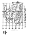
- Figure 1 is a typical performance map of a four cylinder spark ignition passenger car engine having a displacement of approximately 2.5 liters.
- the map is a plot of engine torque T E and brake horsepower BHP as a function of engine speed N E .
- the dot-dash line near the top of the map is a plot of engine torque at full throttle.
- the series of curves in solid black lines are fuel consumption contours, indicating constant brake specific fuel consumption (BSFC) in Ib.M/BHP-h . Minimum fuel consumption occurs at a point designed by 0.4 pounds per horsepower-hour.
- the series of dashed lines indicates power output of the engine.
- the ideal operating line for low fuel consumption is indicated by the heavy solid line f(N E )y this curve being a function of engine speed.
- the ideal operating line for low fuel consumption is purely a function of engine characteristics and is optimal regardless of vehicle road speed.
- Other ideal operating lines may appear on the performance map, for example, the ideal operating line for low emissions.
- forward speed ratios usually are available in only four or five steps.
- the operating point of the engine on the performance map is determined by drive shaft speed, power or torque commanded, and transmission gear ratio. Since there are only a few gear ratios available in a typical transmission, the engine must be throttled much of the time. The engine must therefore operate most of the time at high BSFC values.
- a CVT is able to vary its speed ratio continuously to allow the engine to run at wider throttle and lower BSFC values.
- FIG. 2 schematically illustrates a system devised by Peter Stubbs for British Leyland. This system is described in greater detail in Stubbs, The Development of a Perbury Traction Transmission for Motor Car Applications, ASME Publication No. 80-C2/DET-59 (August, 1980).
- engine speed, throttle position and CVT ratio signals are all fed to a computer controller which has, in its memory, the engine operating characteristic for minimum fuel consumption.
- the computer controller generates, as a function of these variables, an engine control signal for adjusting the position of the throttle, and a ratio rate signal which changes the ratio of the CVT.
- the throttle is under the direct control of the vehicle accelerator pedal so that, while the engine control signal may vary the throttle position somewhat from that commanded by the driver, the throttle position still is primarily a function of commanded power or torque.
- FIG. 3 is a schematic representation of the system devised by Miyao for Aisin Seiki. This system is described in greater detail in U.S.Patent No. 4,091,690.
- engine throttle is primarily a function of commanded power or torque by direct connection with the accelerator pedal.
- the computer generates a ratio rate signal to change the CVT ratio as a function of measured throttle position and engine torque and speed. Inherently sensed output torque also affects the CVT ratio.
- throttle position is controlled directly by the vehicle accelerator pedal, or is a direct function of pedal position, as well as other parameters.
- Engine and transmission control usually are directly related to one another.
- Another object of the invention is to provide such a control scheme which yields substantially constant vehicle driveability as sensed by the driver, irrespective of engine temperature, age, state of tune, altitude and other variables.
- Another object of the invention is to provide such a control scheme in a vehicle whose characteristic will remain the same irrespective of the type of engine which is coupled to the CVT.
- Another object of the invention is to provide such a control scheme in a CVT vehicle, which will enable the vehicle to perform almost in all respects as a vehicle with a conventional transmission.
- Another object of the invention is to greatly simplify calibration of the engine for emissions purposes.
- throttle is understood to encompass any mechanism for controlling the delivery of fuel to the engine or other prime mover, be it a conventional carbure- ted spark-ignition engine wherein fuel flow varies with throttle butterfly position, a fuel injected spark-ignition or diesel engine, a gas turbine, and so on.
- the above and other objects of the invention are accomplished by providing a method of controlling the operation of a power delivery system including a prime mover and a continuously variable ratio transmission coupled to the prime mover for delivering power from the prime mover to an output shaft.
- the prime mover has fuel delivery means for delivering a variable quantity of fuel thereto, and the power delivery system is controlled by command means for commanding a desired system performance parameter, such as output power or torque delivered to the output shaft.
- the method includes the steps of measuring the actual performance of the system, and controlling the ratio of the transmission as a function of the commanded performance parameter and the measured actual performance of the systai the speed of th prime mover varying as a function of transmission ratio.
- a fuel function is predetermined which defines desired fuel requirements for the prime mover in relation to prime mover operating speed.
- the speed of the prime mover is measured, and the fuel delivery means is controlled in accordance with the fuel function so that the fuel delivered to the prime mover is determined only by the speed thereof.
- the command means is temporarily operatively coupled to the fuel delivery means to provide positive driver control of the engine.
- the engine and transmission may be coupled by a clutch which is disengaged when the vehicle is stationary and is partially engaged during slow vehicle operation.
- the invention also encompasses a system for carrying out the above-described method, and a power delivery system including the prime mover, transmission and control system therefor.
- the invention also includes a method of controlling the operation of the engine of an engine-driven vehicle during stationary and relatively slow vehicle operation.
- the vehicle engine is coupled to a CVT and has command means for commanding a desired output power or torque delivered to the output shaft, the drive ratio of the transmission varying as a function of commanded power or torque to thereby cause the speed of the engine to vary.
- the method comprises the steps of predetermining a fuel function defining desired fuel requirements for the engine in relation to engine operating speed, measuring the speed of the engine, controlling the fuel delivery means only in accordance with the fuel function so that the fuel delivered to the engine is determined only by the speed thereof, and operatively coupling the command means to the fuel delivery means during stationary and relatively slow vehicle operation.
- This coupling is dependent upon comparison of a ratio signal, equal to the quotient of measured engine speed and measured output shaft speed, to a predetermined slow operation ratio, the command means being operatively coupled to the fuel delivery means when the ratio signal exceeds the slow operation ratio.
- a system for controlling the engine in accordance with this method also is included.
- FIG. 4 illustrates the functional relationships of the components of the invention.
- An engine 10 is drivingly coupled to a continuously variable ratio transmission (CVI) 14 through a clutch or fluid coupling (not shown).
- Fuel is fed to engine 10 by a fuel delivery means 12, which may be the throttle and fuel jets of a conventional carburetor, a fuel injection system or the like.
- CVT 14 may be one of the many types of continuously variable ratio transmissions discussed above in connection with the prior art.
- Output shaft 16 delivers power and torque from the engine and CVT.
- the ratio of the CVT is set by a CVT ratio controller 17, which generates a rate of change of ratio signal kR as a function of output torque TO measured by torque sensor 19 and commanded power or torque ⁇ commanded by accelerator pedal 18.
- ratio controller 17 may be used to effect a change of CVT ratio in a similar manner.
- CVT ratio is strictly a function of commanded power or torque and measured output torque, and is completely independent of engine operation.
- Engine control is provided by an engine controller 100 which adjusts fuel delivery means 12 in accordance with measured engine speed N E .
- This relationship may desirably be the ideal engine operating line for low fuel consumption, the ideal operating line for low emissions, a compromise of the two, or any other desired engine operating characteristic.
- FIG. 5 schematically illustrates the entire control system in greater detail.
- the particular type of CVT illustrated in Figure 5 is the variable diameter pulley, V-belt traction drive type having a driven sheave 20 connected to output shaft 16 and a driver sheave 30 which is coupled to engine 10.
- Belt 15 interconnects sheaves 20 and 30 to transmit motive power therebetween.
- Sheaves 20 and 30 are hydraulically actuated by pressurized fluid to vary the driving diameters.
- Sheave 20 has an axially fixed portion 22 and an axially movable portion 24.
- Pressurized fluid in a fluid chamber 26 behind movable portion 24 provides the axial force required to maintain portions 22 and 24 at a fixed distance from one another (i.e., to hold the driving diameter of sheave 20 constant), and to move portion 24 toward or away from portion 22 to vary the driving diameter.
- sheave 30 has an axially fixed portion 32 and a movable portion 34 which is under the influence of ' fluid. pressure in chamber 36. Proper pressures in chambers 26 and 36 to keep belt 15 under proper tension are maintained by the control system, as described below.
- throttle (fuel delivery means) 12 is controlled by a throttle servo 13 which receives signals from engine control circuit 100.
- fuel delivery may be diminished by a fuel diminishing valve 11, or fuel delivery may be suspended completely by a fuel suspension mechanism 9.
- the fuel diminishing and suspension functions may be performed, for example, by a single solenoid valve operable in variable modes.
- Engine control circuit 100 is responsive to inputs from the accelerator pedal ( ⁇ ), engine speed (N E ), a manual override switch which permits operation in the automatic or manual mode, and a start/neutral switch (S/N) which insures that the vehicle will remain stationary when the engine is started.
- Fluid pressure for activating the driven sheave is provided by a sheave pressure generator 200 which acts through a pressure servo controller 250 and a fluid distribution circuit 500.
- fluid pressure for activating the driver sheave 30 is provided by sheave pressure generator 300 acting through a servo controller 350 and fluid distribution circuit 500.
- Pressure generator 200 is responsive to inputs of engine speed N E P accelerator position ⁇ , drive shaft N DS measured by a sensor associated with drive shaft 16, and CVT ratio R. Ratio R is generated by CVT ratio circuit 600 and is the quotient of engine speed N E divided by drive shaft speed N DS'
- a starting clutch 40 is provided which couples engine 10 and CVT 14. Clutch 40 is disengaged when the vehicle is stationary, and is partially engaged during slow vehicle operation, gradually approaching full engagement, which occurs as described below at a predetermined point of operation. Starting clutch 40 is controlled by a control circuit 400 which is responsive to accelerator pedal position ⁇ , engine speed N E and the auto/manual switch, througi servo controller 450 and fluid distribution circuit 500.
- Figures 7, 8 and 9 schematically illustrate in greater detail the functional relationships of the components illustrated in Figure 5.
- Figure 7 is primarily directed to the engine control circuit 100.
- a key element of control circuit 100 is function generator 102, which may generate a function representative of any desired engine operating characteristic.
- the function is chosen as the ideal engine operating line for low fuel consumption.
- ⁇ represents throttle angle, which is proportional to desired engine output torque.
- Figure 1 graphically illustrates this function as f(N E ).
- the value of the function produced by generator 102 is fed directly to throttle servo 13 via amplifier 104.
- mode switch 106 In the event the automatic control system is disabled, it is possible to switch to a maual mode through mode switch 106.
- accelerator position is directly communicated to throttle servo 13 via amplifier 104.
- the start/neutral switch S/N also operates through mode switch 106.
- a fuel suspension comparator 108 provides for engine overspeed control, which may tend to occur upon vigorous acceleration or if there.is a malfunction in the control system. Comparator 108 compares engine speed N E to the maximum permissible engine speed, for example, 6000 rpm. If N E is greater than 6000 rpm, fuel suspension mechanism 9 is activated to suspend delivery of fuel to engine 10. Fuel suspension mechanism 9 may be, for example, a solenoid' cutoff valve.
- Another engine speed control is provided to counteract the inherent tendency of the vehicle to speed up when the accelerator pedal is released. This phenomenon occurs upon deceleration because the vehicle inertia becomes coupled to the inertia of a relatively unthrottled engine through a transmission whose ratio is changing towards overdrive.
- a pulse width modulator 110 controls fuel diminishing valve 11, the duty cycle (i.e., the percentage of the pulse cycle during which fuel diminishing valve is held open) of modulator 110 being inversely proportional to the rate at which pedal position ⁇ decreases (- ⁇ ).
- - ⁇ is derived from a differentiator 112 only if ⁇ is less than zero.
- a fuel diminishing comparator 114 reduces the duty cycle of modulator 110 to or near zero when pedal position ⁇ drops to below 3.6%.
- Figure 8 relates primarily to the starting clutch control circuit 400. It will be appreciated that some type of coupling must be provided between the engine and the CVT in order to permit the engine to idle while the vehicle is stationary. A fluid coupling could be used, but the mechanical losses inherent in such a device are antithetical to the desired objective of maximizing fuel economy. A torque converter with a lock-up clutch would be an improvement, but a mechanical clutch is preferred, and one which is hydraulically actuated would be well suited for this purpose. The object here, as in the conventional automobile, is to totally disengage the clutch when the vehicle is stationary, and to gradually engage it to begin vehicle movement and progressively engage the clutch further as the vehicle speed increases.
- the measured transmission ratio R (which is computed as the quotient of engine speed N E and drive shaft speed N DS by ratio circuit 600) is fed to a comparator 402.
- Comparator 402 closes switch 404 when R exceeds 4.7 to deliver the signal from amplifier 406 to throttle servo 13 via amplifier 104.
- This signal is equal to ⁇ -N E ', where N E 'is a function produced by generator 408 equal to K(N E - 1000 rpm).
- the accelerator pedal 18 is coupled directly to throttle 12 in a variable way defined by ⁇ -N E '.
- the constant K is selected such that engine speed cannot exceed 2500 rpm if the clutch is not fully engaged. This direct coupling of accelerator pedal to throttle allows an input to be provided to the system to initiate movement of the vehicle from a stationary position.
- Comparator 402 also closes switch 410 to transmit pedal position ⁇ directly to the clutch pressure servo controller 450. Hence, the degree of engagement of clutch 40 is proportional to pedal position up to the point where ratio R equals 4.7. During this period the degree of direct control of the accelerator pedal over throttle 12 diminishes as engine speed increases in accordance with the above-described relationship.
- Figure 9 relates primarily to the sheave pressure generator for the driven sheave 200 and the sheave pressure generator for the driver sheave 300.
- Pressure generator 200 includes circuitry which changes the transmission ratio to increase the load on the engine if the engine tends to exceed the maximum operating speed of 5500 rpm (N AX ).
- NMIN r p m
- Summing amplifier 232 and clipping circuit 236 act to reduce pressure on the driven sheave 200 to increase the load on the engine.
- Amplifier 232 receives N E , applied to its negative input terminal, and N MAX' applied to its positive input terminal, and produces a summed output signal N MAX -N E .
- This summed output is applied to clipping circuit 236 which is a non-linear device having the characteristic shown in Figure 9. This device can be, for example, a reverse biased diode which produces a negative substantially linear output for negative excursions of its input signal and a zero output for positive excursions.
- N E exceeds N MAX' the input signal applied to circuit 236 will be negative, thereby resulting in a negative output signal.
- This negative output signal is then applied to summing amplifier 210 to reduce the value of its summed output signal in proportion to the amount N E exceeds N MAX .
- the pressure on driven sheave 200 will be proportionally decreased.
- N E is less than N MAX' the input signal applied to clipping circuit 236 will be positive resulting in a zero output signal applied to amplifier 210.
- Such an output signal has no affect on the summed output signal of amplifier 210; thus, no change in the signal supplied to the driven servo-controller 250 is produced.
- Summing amplifier 230 and clipping circuit 234 act to increase pressure on the driven sheave 200 to decrease the load on the engine.
- Amplifier 230 receives N E , applied to its negative input terminal, and N MIN' applied to its positive input terminal, and produces a summed output signal N MIN - N E .
- This summed output is applied to a clipping circuit 234 similar to circuit 236.
- Circuit 234 has a non-linear transfer characteristics which produces a positive substantially linear output for positive excursions of its input signal and a zero output for negative excursions.
- Circuit 234 can be, for example, a forward biased diode. If N e falls below N MIN' the input signal applied to clipping circuit 234 will be positive, thereby resulting in a positive output signal.
- This positive output signal is then applied to summing amplifier 210 to increase the value of its summed output signal in proportion to the amount N E is less than N MIN* As a result, the pressure on driven sheave 200 will be proportionally increased. On the other hand, if N E is greater than N MIN' then a zero output signal will be produced by circuit 234 which has no affect on the summed signal applied to servo-controller 250.
- Pressure generator 200 also includes circuitry for adjusting the sensitivity of accelerator pedal 18, depending on vehicle speed, to more closely simulate the "feel" of a conventional vehicle. This is required because of the inherent operating characteristics of the engine and CVT. That is, at higher vehicle speeds, the torque produced by the engine remains fairly high and constant (see Figure 1). In the conventional vehicle the remaining small percentage of torque which can be extracted from the engine is delivered to the rear wheels through a transmission in high gear with a fixed, very low reduction ratio. Vehicle acceleration is therefore fairly insensitive to accelerator pedal movement at high speeds. In a CVT equipped vehicle, however, depression of the accelerator pedal even at high vehicle speeds results in an increased reduction ratio and an associated multiplication of torque in excess of that provided in the conventional vehicle. Thus, if only direct accelerator pedal position ⁇ were used to control CVT ratio at higher vehicle speeds, vehicle response would be extremely sensitive to accelerator pedal movement. The sensitivity of the accelerator pedal 18 must therefore be dulled at higher vehicle speeds.
- Pedal sensitivity is controlled by two comparators 212,214. As long as vehicle speed is below a threshold equivalent of drive shaft speed N DS equal to or less than 1173 rpm, switch 216 remains closed to deliver the ⁇ signal directly to amplifier 210. This effectively is torque control. When drive shaft speed N DS exceeds 1173 rpm, switch 216 opens and switch 218 is closed so that a pedal position signal equivalent tockdivided by N DS (provided by divider 220) is delivered to amplifier 210. This effectively is power control. In this way, the effect of any movement of accelerator pedal 18 in the higher speed ranges is diminished so as to more closely simulate the pedal response of a conventional automobile.
- Figure 10 shows a modification of the sheave pressure generator 200, wherein accelerator sensitivity is controlled as a function of ratio R.
- Comparator 212' closes switch 216' to connect the accelerator pedal position signal ⁇ directly to amplifier 210 when ratio R equals or exceeds3.
- the comparator 214' closes switch 218' to feed a dulled signal to amplifier 210 from divider 220' when ratio R is below 3.
- the control of transmission ratio described above actually is a ratio rate control, R. That is, the greater the magnitude of the increase (or decrease) in fluid pressure on driven sheave 20 commanded by accelerator pedal 18, the more rapid the change of sheave diameters will be. Thus, for example, a rapid depression of accelerator pedal 18 will result in a rapid change of CVT ratio and quick acceleration. This, of course, closely simulates the characteristics of a conventional vehicle.
- the instant invention involves, in part, the recognition that control of the ratio rate R of the CVT, rather than merely the CVT ratio, yields improved CVT control.
- This improved control is explained by reference to the following derived vehicle performance equation:
- rate of change of ratio is closely approximated by the following relationships: and
- the comparison of accelerator pedal position ⁇ and output torque T 0 occurs inherently in the belt and pulley components to effect a ratio change at a rate R.
- Other types of CVTs may require different control elements to effect this relationship.
- other parameters indicative of system performance may be used to effect a ratio change at a rate R, where R is proportional to the difference between the desired performance parameter and the actual measured performance parameter.
- Figure 11 is a plot of engine speed N E as a function of vehicle speed or drive shaft speed N DS*
- the minimum and maximum CVT ratios are illustrated by the straight lines emanating from the origin of the graph.
- the maximum vehicle speed is defined by a vertical line at the right hand edge of the graph.
- the graph of Figure 11 is divided into a number of discrete operating regions.
- “A” designates the normal region of operation of the engine-CVT system.
- Region “A” is bounded by the line of maximum CVT ratio, the line of maximum engine speed, the line of maximum vehicle speed, the line of minimum CVT ratio and the idle speed line.
- clutch 40 is fully engaged and throttle position is wholly a function of engine speed-in accordance with the fuel function f(N E ).
- Operation to the left of the dashed vertical line indicating a drive shaft speed of 1,173 rpm is under torque control, while operation to the right of this line is under power control (see the above two equations, and the accelerator pedal sensitivity circuitry illustrated in Figures 9 and 10).
- Region “B” is the region of start-up control, that is the operation of the engine-CVT system during slow vehicle operation when clutch 40 is only partially engaged. The control for this operation (400) is illustrated in Figure 8.
- Region “C” is the region of overspeed control, governed by the fuel suspension mechanism 9 and fuel suspension comparator 108 of engine control circuit 100 ( Figure 7), and by amplifier 232 and clipping circuit 236 of sheave pressure generator 200 ( Figure 9).
- Region E is the region of engine idle control which is governed by amplifier 230 and clipping circuit 234 of sheave pressure generator 200 ( Figure 9).
- a load line which indicates the engine speed required to maintain any constant vehicle speed along a level road.
- the term "load” includes road load, final drive losses and the like, and represents the actual load on the engine-CVT system.
- the CVT ratio range include substantially all ratios required to maintain constant vehicle speed for any normally encountered load. That is, the minimum CVT ratio preferably is smaller than that required to maintain constant vehicle speed along a level road, and the maximum CVT ratio preferably is greater than that required to maintain constant vehicle speed up the steepest grade which one might expect to encounter.
- a desirable CVT ratio range for accomplishing this is approximately 11:1 with, for example, a maximum CVT ratio of 22:1 (total vehicle ratio, including final drive ratio), and a minimum CVT ratio of 2:1.
- a transmission having such a wide ratio range is disclosed in commonly assigned Serial No. 290,293, filed August 5, 1981.
- a CVT having a smaller ratio range would be operable, but would not have as much flexibility as one with a wider range.
- the lower curve in Figure 6 is a plot of steady state axial force on movable portion 24 of driven sheave 20 as a function of CVT ratio.
- the upper curve is a plot of steady state axial force tending to resist inward movement of movable portion 34 as a function of CVT ratio.
- Movable portion 24 does not move instantaneously, however, due to the inertia of the system. Accordingly, the curve which represents the transient change taking place in sheave 20 is defined by movement from point A to point B at a constant ratio of 1.0, and then to point C where equilibrium is reached.
- an increase in pressure in chamber 36 of driver sheave 30 results in an increase in axial force on movable portion 34 of sheave 30 from approximately 315 kg (point D) to approximately 380 kg(equilibrium point E).
- the increased tension on belt 15 occasioned by expansion of the diameter of sheave 20 forces the two portions 32, 34 of sheave 30 apart so that sheave 30 has a smaller driving diameter.
- Driver sheave 30, therefore, follows in a controlled manner any changes occuring to driven sheave 20.
- Sheave pressure generator 300 generates a pressure appropriate for driver sheave 30 as a function of ratio R and measured output torque T 0 .
- This function has been found to satisfactorily tension belt 15, without undue stress, and effect a smooth change of ratio.
- An example of a function suitable for this purpose is as follows: Where P DR is the fluid pressure in chamber 36 of driver sheave 30, and K1, K 2 and K 3 are appropriately selected constants.
Abstract
Description
- This invention relates to a power delivery system having a continuously variable ratio transmission and, more particularly, to a control system and a control method for such a system, such as might be used in an automotive vehicle.
- The quest for greater fuel economy of automotive vehicles has led to significant improvements in engine and transmission design and control. Continuously variable ratio transmissions (CVT) have shown particular promise in this regard. It will be appreciated that at any given vehicle speed, and for any needed propulsive force, a certain transmission ratio will provide maximum fuel economy for a given engine. In addition, for any given vehicle speed, one transmission ratio will permit maximum acceleration with that engine. Since a CVT with the proper ratio range can provide any desired transmission ratio, it is obviously attractive for automobiles from the standpoint of economy, low emissions and performance. If the mechanical efficiency of the CVT is high and its ratio range is wide enough, it can even be possible to have both maximum economy and maximum performance in the same vehicle. Among the obvious benefits are fully automatic operation, smooth, stepless and rapid response to driver demand and quieter cruising. Many different CVT configurations have been developed in the prior art. These include, for example, hydrostatic transmissions; rolling contact traction drives; overrunning clutch designs; electrics; multi-speed gear boxes with slipping clutch; and V-belt traction drives. Of these the V-belt traction drives appear attractive for small to medium size passenger car applications because of their compactness, lightness and simplicity of design. Basically, this type of CVT comprises a V-belt which interconnects a driver sheave and driven sheave, the diameters of the sheaves being variable to change the ratio of the CVT. Recent advances in belt design have resulted in improved belt durability and longevity. If sheave movement can be properly controlled so as to avoid undue stresses on the belt, it is expected that a very long belt life can be achieved.
- Many control schemes have been devised for engine-CVT systems in attempts to maximize fuel economy. These have been based on empirical analyses of individual engine performance, and the realization that, for any desired power output, there is an optimum combination of engine speed and torque which will result in minimum fuel consumption. This is illustrated in Figure 1.
- Figure 1 is a typical performance map of a four cylinder spark ignition passenger car engine having a displacement of approximately 2.5 liters. The map is a plot of engine torque TE and brake horsepower BHP as a function of engine speed NE. The dot-dash line near the top of the map is a plot of engine torque at full throttle. The series of curves in solid black lines are fuel consumption contours, indicating constant brake specific fuel consumption (BSFC) in Ib.M/BHP-h . Minimum fuel consumption occurs at a point designed by 0.4 pounds per horsepower-hour. The series of dashed lines indicates power output of the engine. The ideal operating line for low fuel consumption is indicated by the heavy solid line f(N E)y this curve being a function of engine speed. The ideal operating line for low fuel consumption is purely a function of engine characteristics and is optimal regardless of vehicle road speed. Other ideal operating lines may appear on the performance map, for example, the ideal operating line for low emissions. In a vehicle with a conventional, manually shifted gearbox, forward speed ratios usually are available in only four or five steps. The operating point of the engine on the performance map is determined by drive shaft speed, power or torque commanded, and transmission gear ratio. Since there are only a few gear ratios available in a typical transmission, the engine must be throttled much of the time. The engine must therefore operate most of the time at high BSFC values. In contrast, a CVT is able to vary its speed ratio continuously to allow the engine to run at wider throttle and lower BSFC values.
- Perhaps the most difficult task demanded of a control system for an engine-CVT system is to maintain engine operation along the ideal operating line. This is due to the almost continuous transient nature of operation of an automotive vehicle, there being hardly ever a time when road load and commanded torque or power remain constant. Transient conditions usually are dealt with by a change in CVT ratio, engine speed and throttle. Prior art control systems by their very nature, permit an excursion of engine operation away from the ideal operating line before returning back to it at steady state. An example of such an excursion is shown in Figure 1 by dashed line X-Y-Z. The result is that, engine operation approaches, but hardly ever is maintained on the ideal operating line. Two such prior art systems are illustrated in Figures 2 and 3.
- Figure 2 schematically illustrates a system devised by Peter Stubbs for British Leyland. This system is described in greater detail in Stubbs, The Development of a Perbury Traction Transmission for Motor Car Applications, ASME Publication No. 80-C2/DET-59 (August, 1980). In this system, engine speed, throttle position and CVT ratio signals are all fed to a computer controller which has, in its memory, the engine operating characteristic for minimum fuel consumption. The computer controller generates, as a function of these variables, an engine control signal for adjusting the position of the throttle, and a ratio rate signal which changes the ratio of the CVT. The throttle is under the direct control of the vehicle accelerator pedal so that, while the engine control signal may vary the throttle position somewhat from that commanded by the driver, the throttle position still is primarily a function of commanded power or torque.
- Figure 3 is a schematic representation of the system devised by Miyao for Aisin Seiki. This system is described in greater detail in U.S.Patent No. 4,091,690. Here, as in the Stubbs system, engine throttle is primarily a function of commanded power or torque by direct connection with the accelerator pedal. The computer generates a ratio rate signal to change the CVT ratio as a function of measured throttle position and engine torque and speed. Inherently sensed output torque also affects the CVT ratio. In these, as well as in virtually all other engine-CVT control systems, throttle position is controlled directly by the vehicle accelerator pedal, or is a direct function of pedal position, as well as other parameters. Engine and transmission control usually are directly related to one another. Such control schemes permit engine operation during transients to vary from the ideal operating line. Excursions away from the ideal operating line result in less than optimum engine operation (e.g., excessive fuel consumption, or excessive emissions), until effective control is resumed by the system during steady state operation. As pointed out earlier, however, most vehicular operation is transient in nature, rather than steady state, so that substantially all engine operation occurs off the ideal operating line. Emissions calibrations must therefore be made in a substantial portion of the engine performance map. Most prior art control systems also must be specifically tailored to particular engines. This requires numerous specially designed control systems for a fleet of differently powered vehicles. In addition, most prior art control systems cannot compensate for varying engine conditions, the result being vehicle driveability which varies with engine temperature, state of tune, age and altitude. Close duplication of conventional vehicle characteristics also is a problem with prior art CVT control schemes.
- It is therefore an object of the present invention to overcome the above-noted disadvantages and deficiencies of the prior art by providing an engine-CVT control scheme which substantially constantly maintains engine operation along the ideal operating line.
- Another object of the invention is to provide such a control scheme which yields substantially constant vehicle driveability as sensed by the driver, irrespective of engine temperature, age, state of tune, altitude and other variables.
- Another object of the invention is to provide such a control scheme in a vehicle whose characteristic will remain the same irrespective of the type of engine which is coupled to the CVT.
- Another object of the invention is to provide such a control scheme in a CVT vehicle, which will enable the vehicle to perform almost in all respects as a vehicle with a conventional transmission.
- Another object of the invention is to greatly simplify calibration of the engine for emissions purposes.
- Surprisingly, it has been found that engine operation can readily be maintained along the ideal operating line by providing for totally independent engine and transmission control. That is, the position of the engine throttle is totally independent of accelerator pedal position. Throttle position and, hence, engine output torque simply is a function of engine speed only, and that function may be any desired relationship, for example, the ideal operating line for low fuel consumption, the ideal operating line for low emissions, or a compromise ideal operating line for low fuel consumption and low emissions. Torque, power or other desired performance parameters commanded by the accelerator pedal controls CVT ratio, and engine speed is determined by the load placed thereon, which is a function of road load and CVT ratio. Hence, throttle position is precisely adjusted in accordance with the ideal function for any load placed on the engine. With appropriately designed controls, which also are a part of this invention, anomalous engine and vehicle behavior, such as engine overspeed and underspeed conditions, can be prevented, transient start-up from rest can be accommodated, and the vehicle can be made to perform almost in all respects just as a vehicle with a conventional automatic transmission. For convenience, the invention is described throughout this specification-in the context of an engine-CVT propulsion system for an automotive vehicle. It is to be understood, however, that the principles of the invention are equally applicable to any type of power delivery system, including but not limited to other vehicular systems using internal or external combustion engines of any design, or to stationary power plants for driving compressors, generators or any other type of machinery. Where the term "throttle" is used, the term is understood to encompass any mechanism for controlling the delivery of fuel to the engine or other prime mover, be it a conventional carbure- ted spark-ignition engine wherein fuel flow varies with throttle butterfly position, a fuel injected spark-ignition or diesel engine, a gas turbine, and so on.
- The above and other objects of the invention are accomplished by providing a method of controlling the operation of a power delivery system including a prime mover and a continuously variable ratio transmission coupled to the prime mover for delivering power from the prime mover to an output shaft. The prime mover has fuel delivery means for delivering a variable quantity of fuel thereto, and the power delivery system is controlled by command means for commanding a desired system performance parameter, such as output power or torque delivered to the output shaft. The method includes the steps of measuring the actual performance of the system, and controlling the ratio of the transmission as a function of the commanded performance parameter and the measured actual performance of the systai the speed of th prime mover varying as a function of transmission ratio. A fuel function is predetermined which defines desired fuel requirements for the prime mover in relation to prime mover operating speed. The speed of the prime mover is measured, and the fuel delivery means is controlled in accordance with the fuel function so that the fuel delivered to the prime mover is determined only by the speed thereof. In vehicular applications, during stationary and relatively slow vehicle operation, the command means is temporarily operatively coupled to the fuel delivery means to provide positive driver control of the engine. The engine and transmission may be coupled by a clutch which is disengaged when the vehicle is stationary and is partially engaged during slow vehicle operation.
- The invention also encompasses a system for carrying out the above-described method, and a power delivery system including the prime mover, transmission and control system therefor.
- The invention also includes a method of controlling the operation of the engine of an engine-driven vehicle during stationary and relatively slow vehicle operation. The vehicle engine is coupled to a CVT and has command means for commanding a desired output power or torque delivered to the output shaft, the drive ratio of the transmission varying as a function of commanded power or torque to thereby cause the speed of the engine to vary. The method comprises the steps of predetermining a fuel function defining desired fuel requirements for the engine in relation to engine operating speed, measuring the speed of the engine, controlling the fuel delivery means only in accordance with the fuel function so that the fuel delivered to the engine is determined only by the speed thereof, and operatively coupling the command means to the fuel delivery means during stationary and relatively slow vehicle operation. This coupling is dependent upon comparison of a ratio signal, equal to the quotient of measured engine speed and measured output shaft speed, to a predetermined slow operation ratio, the command means being operatively coupled to the fuel delivery means when the ratio signal exceeds the slow operation ratio. A system for controlling the engine in accordance with this method also is included.
- The novel features of the invention are set with particularity in the appended claims, but the invention will be understood more fully and clearly from the following detailed description of the invention as set forth in the accompanying drawings, in which;
- Figure 1 is the performance map of a typical four cylinder passenger car engine having a displacement of approximately 2.5 liters;
- Figures 2 and 3 illustrate two forms of prior art engine-CVT control schemes;
- Figure 4 is a schematic illustration showing the functional relationship of the components of an engine-CVT control scheme according to the invention;
- Figure 5 is a schematic illustration showing the entire control system of the invention and its relationship to the CVT sheave and belt drive, and the vehicle starting clutch:
- Figure 6 is a graph which shows the forces applied to the driver and driven sheaves of the CVT as a function of transmission ratio;
- Figures 7 through 10 together schematically represent the entire engine-CVT control scheme according to the invention,the figures being interrelated as indicated therein by lines A-B and C-D;
- Figure 7 primarily relates to the engine control circuit;
- Figure 8 primarily relates to the starting clutch control circuit;
- Figure 9 primarily relates to the sheave pressure generators;
- Figure 10 illustrates a modification of the pressure generator for the driven sheave illustrated in Figure 9; and
- Figure 11 is a graphical representation of the operation of an engine-CVT system in accordance with the control scheme of the invention.
- Figure 4 illustrates the functional relationships of the components of the invention. An
engine 10 is drivingly coupled to a continuously variable ratio transmission (CVI) 14 through a clutch or fluid coupling (not shown). Fuel is fed toengine 10 by a fuel delivery means 12, which may be the throttle and fuel jets of a conventional carburetor, a fuel injection system or the like.CVT 14 may be one of the many types of continuously variable ratio transmissions discussed above in connection with the prior art.Output shaft 16 delivers power and torque from the engine and CVT. The ratio of the CVT is set by aCVT ratio controller 17, which generates a rate of change of ratio signal kR as a function of output torque TO measured bytorque sensor 19 and commanded power or torque α commanded byaccelerator pedal 18. Other parameters indicative of engine-CVT system performance may be used byratio controller 17 to effect a change of CVT ratio in a similar manner. For example, rather than using desired output power or torque and measured actual output torque, commanded and measured vehicle acceleration, output shaft accelerator or other parameters could be used. In this preferred embodiment, however, CVT ratio is strictly a function of commanded power or torque and measured output torque, and is completely independent of engine operation. Engine control, on the other hand, is provided by anengine controller 100 which adjusts fuel delivery means 12 in accordance with measured engine speed NE. This relationship may desirably be the ideal engine operating line for low fuel consumption, the ideal operating line for low emissions, a compromise of the two, or any other desired engine operating characteristic. - Figure 5 schematically illustrates the entire control system in greater detail. The particular type of CVT illustrated in Figure 5 is the variable diameter pulley, V-belt traction drive type having a driven
sheave 20 connected tooutput shaft 16 and adriver sheave 30 which is coupled toengine 10.Belt 15 interconnects sheaves 20 and 30 to transmit motive power therebetween.Sheaves Sheave 20 has an axially fixedportion 22 and an axiallymovable portion 24. Pressurized fluid in afluid chamber 26 behindmovable portion 24 provides the axial force required to maintainportions sheave 20 constant), and to moveportion 24 toward or away fromportion 22 to vary the driving diameter. Similarly, sheave 30 has an axially fixedportion 32 and amovable portion 34 which is under the influence of 'fluid. pressure inchamber 36. Proper pressures inchambers belt 15 under proper tension are maintained by the control system, as described below. - The position of throttle (fuel delivery means) 12 is controlled by a
throttle servo 13 which receives signals fromengine control circuit 100. During certain transient operations (described below) fuel delivery may be diminished by a fuel diminishing valve 11, or fuel delivery may be suspended completely by afuel suspension mechanism 9. The fuel diminishing and suspension functions may be performed, for example, by a single solenoid valve operable in variable modes.Engine control circuit 100 is responsive to inputs from the accelerator pedal (α), engine speed (NE), a manual override switch which permits operation in the automatic or manual mode, and a start/neutral switch (S/N) which insures that the vehicle will remain stationary when the engine is started. - Fluid pressure for activating the driven sheave is provided by a
sheave pressure generator 200 which acts through apressure servo controller 250 and afluid distribution circuit 500. Similarly, fluid pressure for activating thedriver sheave 30 is provided bysheave pressure generator 300 acting through aservo controller 350 andfluid distribution circuit 500.Pressure generator 200 is responsive to inputs of engine speed NEP accelerator position α, drive shaft NDS measured by a sensor associated withdrive shaft 16, and CVT ratio R. Ratio R is generated byCVT ratio circuit 600 and is the quotient of engine speed NE divided by drive shaft speed N DS' - A starting
clutch 40 is provided which couplesengine 10 andCVT 14.Clutch 40 is disengaged when the vehicle is stationary, and is partially engaged during slow vehicle operation, gradually approaching full engagement, which occurs as described below at a predetermined point of operation. Startingclutch 40 is controlled by acontrol circuit 400 which is responsive to accelerator pedal position α, engine speed NE and the auto/manual switch,througi servo controller 450 andfluid distribution circuit 500. - Figures 7, 8 and 9 schematically illustrate in greater detail the functional relationships of the components illustrated in Figure 5. Figure 7 is primarily directed to the
engine control circuit 100. A key element ofcontrol circuit 100 isfunction generator 102, which may generate a function representative of any desired engine operating characteristic. For this embodiment the function is chosen as the ideal engine operating line for low fuel consumption. ⊖ represents throttle angle, which is proportional to desired engine output torque. Figure 1 graphically illustrates this function as f(NE). The value of the function produced bygenerator 102 is fed directly tothrottle servo 13 viaamplifier 104. In the event the automatic control system is disabled, it is possible to switch to a maual mode throughmode switch 106. In the manual mode, accelerator position is directly communicated to throttleservo 13 viaamplifier 104. The start/neutral switch S/N also operates throughmode switch 106. - A
fuel suspension comparator 108 provides for engine overspeed control, which may tend to occur upon vigorous acceleration or if there.is a malfunction in the control system.Comparator 108 compares engine speed NE to the maximum permissible engine speed, for example, 6000 rpm. If NE is greater than 6000 rpm,fuel suspension mechanism 9 is activated to suspend delivery of fuel toengine 10.Fuel suspension mechanism 9 may be, for example, a solenoid' cutoff valve. - Another engine speed control is provided to counteract the inherent tendency of the vehicle to speed up when the accelerator pedal is released. This phenomenon occurs upon deceleration because the vehicle inertia becomes coupled to the inertia of a relatively unthrottled engine through a transmission whose ratio is changing towards overdrive.
- This undesirable tendency is even more pronounced when the accelerator pedal is released suddenly and completely.
- This anomalous behavior is prevented by reducing fuel flow to the engine when pressure on the accelerator pedal is relieved, the reduction of fuel flow being proportional to the rate at which pedal position decreases (-α), and by reducing fuel flow even further when the accelerator pedal position α drops to below 3.6% of full excursion. To accomplish this control, a
pulse width modulator 110 controls fuel diminishing valve 11, the duty cycle (i.e., the percentage of the pulse cycle during which fuel diminishing valve is held open) ofmodulator 110 being inversely proportional to the rate at which pedal position α decreases (-α). -α is derived from adifferentiator 112 only if α is less than zero. In addition, afuel diminishing comparator 114 reduces the duty cycle ofmodulator 110 to or near zero when pedal positionαdrops to below 3.6%. - Figure 8 relates primarily to the starting
clutch control circuit 400. It will be appreciated that some type of coupling must be provided between the engine and the CVT in order to permit the engine to idle while the vehicle is stationary. A fluid coupling could be used, but the mechanical losses inherent in such a device are antithetical to the desired objective of maximizing fuel economy. A torque converter with a lock-up clutch would be an improvement, but a mechanical clutch is preferred, and one which is hydraulically actuated would be well suited for this purpose. The object here, as in the conventional automobile, is to totally disengage the clutch when the vehicle is stationary, and to gradually engage it to begin vehicle movement and progressively engage the clutch further as the vehicle speed increases. To this end the measured transmission ratio R (which is computed as the quotient of engine speed NE and drive shaft speed NDS by ratio circuit 600) is fed to acomparator 402.Comparator 402 closes switch 404 when R exceeds 4.7 to deliver the signal fromamplifier 406 to throttleservo 13 viaamplifier 104. This signal is equal to α-NE', where NE'is a function produced bygenerator 408 equal to K(NE - 1000 rpm). Thus, theaccelerator pedal 18 is coupled directly to throttle 12 in a variable way defined by α-NE'. The constant K is selected such that engine speed cannot exceed 2500 rpm if the clutch is not fully engaged. This direct coupling of accelerator pedal to throttle allows an input to be provided to the system to initiate movement of the vehicle from a stationary position. -
Comparator 402 also closesswitch 410 to transmit pedal position α directly to the clutchpressure servo controller 450. Hence, the degree of engagement ofclutch 40 is proportional to pedal position up to the point where ratio R equals 4.7. During this period the degree of direct control of the accelerator pedal overthrottle 12 diminishes as engine speed increases in accordance with the above-described relationship. - When ratio R drops below 4.7, switches 404 and 410 open, and
comparator 411 closes switch 412 to deliver maximum pressure to theclutch servo controller 450. Maximum pressure causes full engagement of the clutch. As the vehicle accelerates beyond this point, it is under total automatic control. - It can be seen that if no start/neutral S/N switch were provided, any depression of
accelerator pedal 18 upon start up would cause engagement ofclutch 40 and a forward lurch of the vehicle. The S/N switch therefore effectively disables the effect ofo(on clutch 40 to permit safe startup. - Figure 9 relates primarily to the sheave pressure generator for the driven
sheave 200 and the sheave pressure generator for thedriver sheave 300.Pressure generator 200 includes circuitry which changes the transmission ratio to increase the load on the engine if the engine tends to exceed the maximum operating speed of 5500 rpm (NAX). - Also provided is circuitry for changing the transmission ratio to decrease the load on the engine should the engine speed tend to decrease below the idle speed of 1000 rpm (NMIN). This is accomplished by means of summing
amplifiers circuits amplifier 232 and clippingcircuit 236 act to reduce pressure on the drivensheave 200 to increase the load on the engine.Amplifier 232 receives NE, applied to its negative input terminal, and NMAX' applied to its positive input terminal, and produces a summed output signal NMAX-NE. This summed output is applied to clippingcircuit 236 which is a non-linear device having the characteristic shown in Figure 9. This device can be, for example, a reverse biased diode which produces a negative substantially linear output for negative excursions of its input signal and a zero output for positive excursions. - Consequently, if NE exceeds NMAX' the input signal applied to
circuit 236 will be negative, thereby resulting in a negative output signal. This negative output signal is then applied to summingamplifier 210 to reduce the value of its summed output signal in proportion to the amount NE exceeds NMAX. As a result, the pressure on drivensheave 200 will be proportionally decreased. On the other hand, if NE is less than NMAX' the input signal applied to clippingcircuit 236 will be positive resulting in a zero output signal applied toamplifier 210. Such an output signal has no affect on the summed output signal ofamplifier 210; thus, no change in the signal supplied to the driven servo-controller 250 is produced. - Summing
amplifier 230 and clippingcircuit 234 act to increase pressure on the drivensheave 200 to decrease the load on the engine.Amplifier 230 receives NE, applied to its negative input terminal, and NMIN' applied to its positive input terminal, and produces a summed output signal N MIN- NE. This summed output is applied to aclipping circuit 234 similar tocircuit 236.Circuit 234, however, has a non-linear transfer characteristics which produces a positive substantially linear output for positive excursions of its input signal and a zero output for negative excursions.Circuit 234 can be, for example, a forward biased diode. If Ne falls below NMIN' the input signal applied to clippingcircuit 234 will be positive, thereby resulting in a positive output signal. This positive output signal is then applied to summingamplifier 210 to increase the value of its summed output signal in proportion to the amount NE is less than NMIN* As a result, the pressure on drivensheave 200 will be proportionally increased. On the other hand, if NE is greater than NMIN' then a zero output signal will be produced bycircuit 234 which has no affect on the summed signal applied to servo-controller 250. -
Pressure generator 200 also includes circuitry for adjusting the sensitivity ofaccelerator pedal 18, depending on vehicle speed, to more closely simulate the "feel" of a conventional vehicle. This is required because of the inherent operating characteristics of the engine and CVT. That is, at higher vehicle speeds, the torque produced by the engine remains fairly high and constant (see Figure 1). In the conventional vehicle the remaining small percentage of torque which can be extracted from the engine is delivered to the rear wheels through a transmission in high gear with a fixed, very low reduction ratio. Vehicle acceleration is therefore fairly insensitive to accelerator pedal movement at high speeds. In a CVT equipped vehicle, however, depression of the accelerator pedal even at high vehicle speeds results in an increased reduction ratio and an associated multiplication of torque in excess of that provided in the conventional vehicle. Thus, if only direct accelerator pedal position α were used to control CVT ratio at higher vehicle speeds, vehicle response would be extremely sensitive to accelerator pedal movement. The sensitivity of theaccelerator pedal 18 must therefore be dulled at higher vehicle speeds. - Pedal sensitivity is controlled by two comparators 212,214. As long as vehicle speed is below a threshold equivalent of drive shaft speed NDS equal to or less than 1173 rpm,
switch 216 remains closed to deliver the α signal directly toamplifier 210. This effectively is torque control. When drive shaft speed NDS exceeds 1173 rpm,switch 216 opens and switch 218 is closed so that a pedal position signal equivalent tockdivided by NDS (provided by divider 220) is delivered toamplifier 210. This effectively is power control. In this way, the effect of any movement ofaccelerator pedal 18 in the higher speed ranges is diminished so as to more closely simulate the pedal response of a conventional automobile. - Figure 10 shows a modification of the
sheave pressure generator 200, wherein accelerator sensitivity is controlled as a function of ratio R. Comparator 212' closes switch 216' to connect the accelerator pedal position signal α directly toamplifier 210 when ratio R equals or exceeds3. The comparator 214'closes switch 218' to feed a dulled signal to amplifier 210 from divider 220' when ratio R is below 3. - The control of transmission ratio described above actually is a ratio rate control, R. That is, the greater the magnitude of the increase (or decrease) in fluid pressure on driven
sheave 20 commanded byaccelerator pedal 18, the more rapid the change of sheave diameters will be. Thus, for example, a rapid depression ofaccelerator pedal 18 will result in a rapid change of CVT ratio and quick acceleration. This, of course, closely simulates the characteristics of a conventional vehicle. - The instant invention involves, in part, the recognition that control of the ratio rate R of the CVT, rather than merely the CVT ratio, yields improved CVT control. This improved control is explained by reference to the following derived vehicle performance equation:

- IEQ = ICDS + R2IE,
- R is the ratio rate of the transmission,
- R is the ratio of the transmission,
- IE is engine inertia,
- NE is engine speed,
- TE is engine torque,
- TRL is road load torque reflected to the drive shaft
- and includes tires, final drive and axle losses, Tloss is transmission loss,
- ICDS is car inertia reflected to the drive shaft, and DS is vehicle acceleration measured at the drive shaft.
- It is clear that the acceleration of the vehicle NDS is dependent primarily upon control of any one or more of these variable such as, for example, TE, R or R. Generally, conventional vehicle systems vary the transmission ratio R and engine output torque TE to provide the required transmission and vehicle control. By controlling R, however, it is difficult to constantly maintain engine torque and speed along the ideal operating line. This is due to the fact that each time R is varied, the load on the engine is changed which, in turn, affects the engine's output torque and vehicle acceleration.
- Attempts to simultaneously change the engine torque and speed to force engine operation back on the ideal line have necessitated very complex control systems, since control is dependent on several variables of the performance system. For example, these systems must necessarily perform the complicated task of calculating the necessary target throttle position and CVT ratio R to force engine operation back on the ideal line. These systems also require the calculation of ratio rate R so that the rate in changing the ratio to the target value does not result in undesirable vehicle dynamics. For example, if R is selected to be excessive then an undesirable decelration of the vehicle will occur before the vehicle can accelerate. This phenomenon results from the negative sign of the R term in the above performance equation.
- This invention, however, recognizes that R can easily be sensed and controlled without causing the other variables to adversely affect engine performance. This is accomplished by separating the engine control from the transmission control so that engine torque and speed are fixed along the ideal engine operating line. As a result of controlling R no adverse affect on the other dependent variables occur. In particular, changing R alone, with its concomitant change on R, will not force engine operation off the ideal operating line since engine speed and torque are determined solely by the fuel function f(NE). As a result, vehicle acceleration NDS and output torque TO are controlled solely by ratio rate R, rather than by the other variables of the performance system.
- It has been discovered in accordance with this invention that rate of change of ratio (R) is closely approximated by the following relationships:


- The above described control scheme of the invention is graphically illustrated in Figure 11. Figure 11 is a plot of engine speed NE as a function of vehicle speed or drive shaft speed NDS* The minimum and maximum CVT ratios are illustrated by the straight lines emanating from the origin of the graph. The idle speed (NMIN=1000 rpm) is indicated by a lower horizontal line, while the maximum permissible engine speed (NMAX=5500 rpm) is indicated by an upper horizontal line. The maximum vehicle speed is defined by a vertical line at the right hand edge of the graph.
- The graph of Figure 11 is divided into a number of discrete operating regions. "A" designates the normal region of operation of the engine-CVT system. Region "A" is bounded by the line of maximum CVT ratio, the line of maximum engine speed, the line of maximum vehicle speed, the line of minimum CVT ratio and the idle speed line. During operation of the system in region "A", clutch 40 is fully engaged and throttle position is wholly a function of engine speed-in accordance with the fuel function f(NE). Operation to the left of the dashed vertical line indicating a drive shaft speed of 1,173 rpm is under torque control, while operation to the right of this line is under power control (see the above two equations, and the accelerator pedal sensitivity circuitry illustrated in Figures 9 and 10). Region "B" is the region of start-up control, that is the operation of the engine-CVT system during slow vehicle operation when clutch 40 is only partially engaged. The control for this operation (400) is illustrated in Figure 8.
- Operation of the engine-CVT system in the remaining three regions "C", "D" and "E" is effectively prevented by the above described control system. That is, operation in region "C" is prevented by the physical limitation of minimum CVT ratio, and by the fuel diminishing circuits comprising fuel diminishing valve 11,
pulse width modulator 110,differentiator 112 andfuel diminishing comparator 114 of engine control circuit 100 (Figure 7). Region "D" is the region of overspeed control, governed by thefuel suspension mechanism 9 andfuel suspension comparator 108 of engine control circuit 100 (Figure 7), and byamplifier 232 and clippingcircuit 236 of sheave pressure generator 200 (Figure 9). Region E is the region of engine idle control which is governed byamplifier 230 and clippingcircuit 234 of sheave pressure generator 200 (Figure 9). Also shown on the graph of Figure 11 is a load line which indicates the engine speed required to maintain any constant vehicle speed along a level road. The term "load" includes road load, final drive losses and the like, and represents the actual load on the engine-CVT system. In order for the control scheme of the invention to function only in accordance with the fuel function so as to maintain engine operation along the ideal operating line, it is desirable that the CVT ratio range include substantially all ratios required to maintain constant vehicle speed for any normally encountered load. That is, the minimum CVT ratio preferably is smaller than that required to maintain constant vehicle speed along a level road, and the maximum CVT ratio preferably is greater than that required to maintain constant vehicle speed up the steepest grade which one might expect to encounter. This relationship is graphically illustrated by the physical location of the load line in the graph of Figure 11 above the line of minimum CVT ratio in region "A". All other load lines should lie below the line of maximum CVT ratio. A desirable CVT ratio range for accomplishing this is approximately 11:1 with, for example, a maximum CVT ratio of 22:1 (total vehicle ratio, including final drive ratio), and a minimum CVT ratio of 2:1. A transmission having such a wide ratio range is disclosed in commonly assigned Serial No. 290,293, filed August 5, 1981. Of course, a CVT having a smaller ratio range would be operable, but would not have as much flexibility as one with a wider range. Referring to Figure 6, the mechanics of a change in CVT ratio now will be described with reference to the axial forces produced by the pressurized fluid inchambers movable portion 24 of drivensheave 20 as a function of CVT ratio. Similarly, the upper curve is a plot of steady state axial force tending to resist inward movement ofmovable portion 34 as a function of CVT ratio. As described below, when for example a signal is generated to increase the ratio of the CVT from 1.0 to approximately 1.7 the fluid pressure inchamber 26 is increased to raise the axial force from approximately 175 kg to, ultimately, approximately 270 kg.Movable portion 24 does not move instantaneously, however, due to the inertia of the system. Accordingly, the curve which represents the transient change taking place insheave 20 is defined by movement from point A to point B at a constant ratio of 1.0, and then to point C where equilibrium is reached. Correspondingly, an increase in pressure inchamber 36 ofdriver sheave 30 results in an increase in axial force onmovable portion 34 ofsheave 30 from approximately 315 kg (point D) to approximately 380 kg(equilibrium point E). Despite this increase in axial force, the increased tension onbelt 15 occasioned by expansion of the diameter ofsheave 20 forces the twoportions sheave 30 apart so thatsheave 30 has a smaller driving diameter.Driver sheave 30, therefore, follows in a controlled manner any changes occuring to drivensheave 20. -
Sheave pressure generator 300 generates a pressure appropriate fordriver sheave 30 as a function of ratio R and measured output torque T0. This function has been found to satisfactorilytension belt 15, without undue stress, and effect a smooth change of ratio. An example of a function suitable for this purpose is as follows:
chamber 36 ofdriver sheave 30, and K1, K2 and K3 are appropriately selected constants. - The above-described control scheme quite simply and effectively accomplishes its primary objective of maintaining engine operation along the ideal operating line, for example, that of minimum fuel consumption. Transmission control requires output torque and accelerator pedal position sensing, while engine control requires only engine speed sensing. The specific parameter values set forth in the preferred embodiment described above are in no way intended to limit the scope of the invention, it being apparent that these parameters will vary in accordance with engine, transmission and vehicle design, and desired behavior and performance. While an electronic control system has been schematically illustrated in the preferred embodiment, it is to be understood that any type of control system which functions in a similar manner may be used. It would appear that a control system incorporating many mechanical components would perhaps be the most reliable and least expensive alternative. Numerous other modifications of the invention will be apparent to those skilled in the art without departing from the true spirit and scope of the invention which is defined by the appended claims.
Claims (67)
Applications Claiming Priority (2)
| Application Number | Priority Date | Filing Date | Title |
|---|---|---|---|
| US06/380,922 US4459878A (en) | 1982-05-21 | 1982-05-21 | Control system and method for a power delivery system having a continuously variable ratio transmission |
| US380922 | 1982-05-21 |
Publications (2)
| Publication Number | Publication Date |
|---|---|
| EP0095147A1 true EP0095147A1 (en) | 1983-11-30 |
| EP0095147B1 EP0095147B1 (en) | 1987-07-29 |
Family
ID=23502977
Family Applications (1)
| Application Number | Title | Priority Date | Filing Date |
|---|---|---|---|
| EP83104974A Expired EP0095147B1 (en) | 1982-05-21 | 1983-05-19 | Control system and method for a power delivery system having a continuously variable ratio transmission |
Country Status (4)
| Country | Link |
|---|---|
| US (1) | US4459878A (en) |
| EP (1) | EP0095147B1 (en) |
| JP (1) | JPS5934056A (en) |
| DE (1) | DE3372734D1 (en) |
Cited By (5)
| Publication number | Priority date | Publication date | Assignee | Title |
|---|---|---|---|---|
| EP0151038A2 (en) * | 1984-01-31 | 1985-08-07 | Fuji Jukogyo Kabushiki Kaisha | System for controlling an elektromagnetic clutch for a vehicle |
| EP0151043A2 (en) * | 1984-01-31 | 1985-08-07 | Fuji Jukogyo Kabushiki Kaisha | System for controlling an electromagnetic clutch of a vehicle |
| EP0153051A1 (en) * | 1984-01-31 | 1985-08-28 | Fuji Jukogyo Kabushiki Kaisha | System for controlling an electromagnetic clutch for a vehicle |
| AU591259B2 (en) * | 1986-04-11 | 1989-11-30 | Eaton Corporation | Selective transmission speed control |
| EP0451887A1 (en) * | 1990-04-12 | 1991-10-16 | Van Doorne's Transmissie B.V. | Electronically controlled continuously variable transmission |
Families Citing this family (47)
| Publication number | Priority date | Publication date | Assignee | Title |
|---|---|---|---|---|
| DE3375381D1 (en) * | 1982-04-19 | 1988-02-25 | Nissan Motor | Method and apparatus for controlling reduction ratio of continuously variable transmission |
| US4598611A (en) * | 1982-05-21 | 1986-07-08 | Aisin Seiki Kabushiki Kaisha | Low power control system and method for a power delivery system having a continuously variable ratio transmission |
| JPS5926657A (en) * | 1982-08-04 | 1984-02-10 | Toyota Motor Corp | Control apparatus for vehicle equipped with stepless transmission type power transmitting mechanism |
| US4712453A (en) * | 1982-09-22 | 1987-12-15 | Borg-Warner Corporation | Hydraulic control system for continuously variable transmission |
| US4583627A (en) * | 1982-10-22 | 1986-04-22 | Nissan Motor Co., Ltd. | Vehicle/engine operational parameter responsive clutch control |
| JPS5977157A (en) * | 1982-10-22 | 1984-05-02 | Nissan Motor Co Ltd | Hydraulic control device for v-belt type stepless speed change gear |
| US4576265A (en) * | 1982-10-22 | 1986-03-18 | Nissan Motor Co., Ltd. | Control system for hydraulic automatic clutch |
| US4771656A (en) * | 1982-11-29 | 1988-09-20 | Toyota Jidoshi Kabushiki Kaisha | Cruise control method and apparatus for a vehicle with a continuously variable transmission |
| US4559850A (en) * | 1982-11-30 | 1985-12-24 | Aisin-Warner, Ltd. | Stepless automatic transmission for motor vehicles |
| DE3379415D1 (en) * | 1982-12-17 | 1989-04-20 | Nissan Motor | Control method for continuously variable transmission or the like |
| JPS59144850A (en) * | 1983-02-07 | 1984-08-20 | Toyota Motor Corp | Method of controlling stepless transmission for vehicle |
| US4583423A (en) * | 1983-02-24 | 1986-04-22 | Ford Motor Company | Infinitely variable transmission for automotive vehicle driveline |
| JPS59187145A (en) * | 1983-03-26 | 1984-10-24 | Mazda Motor Corp | Drive control device for automobile |
| JPS59190554A (en) * | 1983-04-11 | 1984-10-29 | Mazda Motor Corp | Drive control device for automobile |
| JPS59197658A (en) * | 1983-04-26 | 1984-11-09 | Mazda Motor Corp | Drive controller for car |
| JPS59217051A (en) * | 1983-05-23 | 1984-12-07 | Toyota Motor Corp | Control for stepless speed change gear for car |
| US4594666A (en) * | 1983-07-11 | 1986-06-10 | J. I. Case Company | Transmission monitor/control microprocessor for continuously variable power train |
| JPH066979B2 (en) * | 1983-08-22 | 1994-01-26 | トヨタ自動車株式会社 | Control device for continuously variable transmission for vehicle |
| JPS6044649A (en) * | 1983-08-22 | 1985-03-09 | Toyota Motor Corp | Control method of continuously variable transmission for vehicle |
| JPS6044651A (en) * | 1983-08-22 | 1985-03-09 | Toyota Motor Corp | Control method of continuously variable transmission for vehicle |
| JPH066976B2 (en) * | 1983-08-29 | 1994-01-26 | トヨタ自動車株式会社 | Hydraulic control system for belt type continuously variable transmission |
| JPS6053261A (en) * | 1983-09-01 | 1985-03-26 | Toyota Motor Corp | Velocity ratio controller for continuously variable transmission of vehicle |
| JPH07113402B2 (en) * | 1983-09-30 | 1995-12-06 | アイシン精機株式会社 | Drive system device using continuously variable transmission |
| JPS6088259A (en) * | 1983-10-19 | 1985-05-18 | Toyota Motor Corp | Control of continuously variable transmission for car |
| JPS6098253A (en) * | 1983-10-31 | 1985-06-01 | Mazda Motor Corp | Electronic control type stepless speed change gear |
| US4612827A (en) * | 1984-03-30 | 1986-09-23 | Aisin Seiki Kabushiki Kaisha | Accelerator control for a vehicular propulsion system having a continuously variable ratio transmission |
| JP2506630B2 (en) * | 1984-09-13 | 1996-06-12 | アイシン精機株式会社 | CVT control method |
| JPS61119856A (en) * | 1984-09-25 | 1986-06-07 | Toyota Motor Corp | Method and device of controlling driving force of vehicle with continuously variable transmission |
| JPS6181227A (en) * | 1984-09-27 | 1986-04-24 | Mitsubishi Heavy Ind Ltd | Device for speed-change control |
| US4699025A (en) * | 1985-09-30 | 1987-10-13 | Aisin Seiki Kabushiki Kaisha | Method and apparatus for controlling a power delivery system having a continuously variable ratio transmission |
| US4700590A (en) * | 1985-09-30 | 1987-10-20 | Aisin Seiki Kabushiki Kaisha | System for utilizing the negative torque of a power delivery system having a continuously variable ratio transmission for braking |
| JPH0657508B2 (en) * | 1985-11-18 | 1994-08-03 | 富士重工業株式会社 | Controller for continuously variable transmission |
| JPH0780426B2 (en) * | 1986-03-20 | 1995-08-30 | ヤマハ発動機株式会社 | Reverse speed control device for saddle type vehicle for running on rough terrain |
| JP2697828B2 (en) * | 1987-08-28 | 1998-01-14 | 株式会社日立製作所 | Automatic transmission for vehicles |
| JPH0788148B2 (en) * | 1988-11-30 | 1995-09-27 | スズキ株式会社 | Clutch pressure control device for continuously variable transmission |
| JPH03189461A (en) * | 1989-12-18 | 1991-08-19 | Mazda Motor Corp | Speed change ratio control device for continuously variable transmission |
| US5047937A (en) * | 1990-06-01 | 1991-09-10 | General Motors Corporation | Engine CVT control system |
| US5046177A (en) * | 1990-06-01 | 1991-09-03 | General Motors Corporation | Engine-CVT performance mode system |
| JPH05226047A (en) * | 1991-03-18 | 1993-09-03 | Hitachi Ltd | Commutator with built-in capacitor and manufacture thereof |
| JP3200901B2 (en) * | 1991-12-20 | 2001-08-20 | 株式会社日立製作所 | Electric vehicle drive |
| DE19961312C1 (en) * | 1999-12-18 | 2001-06-28 | Bayerische Motoren Werke Ag | Method and device for controlling a continuously variable automatic transmission |
| US7097587B2 (en) * | 2004-08-12 | 2006-08-29 | Daimlerchrysler Corporation | Ratio selection method for a continuously variable transmission |
| US8024925B2 (en) * | 2005-11-08 | 2011-09-27 | Caterpillar Inc. | Apparatus, system, and method for controlling a desired torque output |
| US8165765B2 (en) | 2010-05-28 | 2012-04-24 | Caterpillar Inc. | Variator pressure-set torque control |
| US8744707B2 (en) * | 2011-03-31 | 2014-06-03 | Caterpillar Inc. | CVT control using state space based gain scheduling |
| EP2921676B1 (en) | 2014-03-21 | 2017-08-02 | Perkins Engines Company Limited | Process and system for controlling engine speed |
| CN105673831B (en) * | 2015-12-24 | 2018-03-16 | 奇瑞汽车股份有限公司 | A kind of shifting control method of buncher |
Citations (8)
| Publication number | Priority date | Publication date | Assignee | Title |
|---|---|---|---|---|
| DE2744627A1 (en) * | 1976-10-05 | 1978-04-06 | Volvo Car Bv | CONTINUOUSLY ADJUSTABLE BELTING GEAR |
| US4091690A (en) * | 1976-09-28 | 1978-05-30 | Aisin Seiki Kabushiki Kaisha | Method for controlling continuously variable drive ratio transmissions and a system therefor |
| DE2811574A1 (en) * | 1978-03-17 | 1979-09-27 | Bosch Gmbh Robert | DEVICE FOR THE CONTROL OF A DRIVE MOTOR-GEAR UNIT OF A MOTOR VEHICLE |
| DE2927707A1 (en) * | 1978-07-17 | 1980-01-31 | Sundstrand Corp | ENGINE AND TRANSMISSION CONTROL DEVICE |
| FR2463696A1 (en) * | 1979-08-21 | 1981-02-27 | Volkswagenwerk Ag | Control for automatic transmission - has fuel economy priority with optimum gearing for throttle setting |
| FR2464852A1 (en) * | 1979-09-12 | 1981-03-20 | Bosch Gmbh Robert | CONTROL DEVICE FOR A CONTINUOUS ADJUSTMENT MECHANISM FOR FUEL CONFORMING AN AUTOMOBILE COMBUSTION ENGINE |
| GB2057600A (en) * | 1978-12-09 | 1981-04-01 | Piv Antrieb Reimers Kg Werner | Expanding Pulley Gear Control |
| EP0071801A1 (en) * | 1981-08-05 | 1983-02-16 | Aisin Seiki Kabushiki Kaisha | A variable V-belt type continuously variable transmission for vehicles |
Family Cites Families (21)
| Publication number | Priority date | Publication date | Assignee | Title |
|---|---|---|---|---|
| US24347A (en) * | 1859-06-07 | Washing-machine | ||
| US2131157A (en) * | 1931-03-09 | 1938-09-27 | Gen Motors Corp | Control for variable speed power transmissions |
| US2059591A (en) * | 1934-07-11 | 1936-11-03 | Leoni Pilade | Automatic variable gear ratio transmission |
| US3044316A (en) * | 1955-01-07 | 1962-07-17 | Lloyd M Forster | Continuously variable transmission and automatic control |
| FR1182150A (en) * | 1957-09-09 | 1959-06-23 | Automatic gear transmission device, more particularly for motor vehicles | |
| US3008341A (en) * | 1959-07-06 | 1961-11-14 | Marvin E Cobb | Transmission mechanism |
| GB1035822A (en) * | 1963-01-11 | 1966-07-13 | Dowty Hydraulic Units Ltd | Infinitely variable transmission |
| US3368426A (en) * | 1965-03-12 | 1968-02-13 | Reimers Getriebe A G | Control mechanism for engine combined with infinitely variable transmission |
| US3552232A (en) * | 1966-09-26 | 1971-01-05 | Deere & Co | Transmission control |
| US3616706A (en) * | 1968-05-18 | 1971-11-02 | Yamaha Motor Co Ltd | Transmission device of a sheave drive type |
| FR2188688A5 (en) * | 1972-06-02 | 1974-01-18 | Peugeot & Renault | |
| GB1412557A (en) * | 1972-08-23 | 1975-11-05 | Elektr Strassenverkehr Ges | Electrically propelled vehicles |
| US4023442A (en) * | 1973-08-16 | 1977-05-17 | Oklahoma State University | Automatic control means for infinitely variable transmission |
| US4008567A (en) * | 1975-04-28 | 1977-02-22 | Joseph Hirsch | Torque control system |
| GB1525861A (en) * | 1975-10-23 | 1978-09-20 | Mullard Ltd | Vehicle power transmission arrangements and electronic control means therefor |
| NL165821C (en) * | 1976-02-09 | 1981-05-15 | Doornes Transmissie Bv | INFLATABLE VARIABLE TRANSMISSION. |
| DE2642738C2 (en) * | 1976-09-23 | 1986-08-07 | Robert Bosch Gmbh, 7000 Stuttgart | Method for regulating the operating behavior of an internal combustion engine in a specified operating range |
| JPS5472359A (en) * | 1977-11-21 | 1979-06-09 | Aisin Seiki Co Ltd | Speed ratio control system for stageless speed change gear in vehicle |
| IE46274B1 (en) * | 1977-12-12 | 1983-04-20 | Kiely Denis Martin | A variable speed drive for a battery-powered electric vehicle |
| DE2843256A1 (en) * | 1978-10-04 | 1980-04-17 | Bosch Gmbh Robert | DEVICE FOR REGULATING A MOTOR VEHICLE DRIVE UNIT |
| JPS58189713A (en) * | 1982-04-30 | 1983-11-05 | Toyota Motor Corp | Motive power device for vehicle |
-
1982
- 1982-05-21 US US06/380,922 patent/US4459878A/en not_active Expired - Lifetime
-
1983
- 1983-05-19 EP EP83104974A patent/EP0095147B1/en not_active Expired
- 1983-05-19 DE DE8383104974T patent/DE3372734D1/en not_active Expired
- 1983-05-20 JP JP58089887A patent/JPS5934056A/en active Granted
Patent Citations (9)
| Publication number | Priority date | Publication date | Assignee | Title |
|---|---|---|---|---|
| US4091690A (en) * | 1976-09-28 | 1978-05-30 | Aisin Seiki Kabushiki Kaisha | Method for controlling continuously variable drive ratio transmissions and a system therefor |
| DE2744627A1 (en) * | 1976-10-05 | 1978-04-06 | Volvo Car Bv | CONTINUOUSLY ADJUSTABLE BELTING GEAR |
| DE2811574A1 (en) * | 1978-03-17 | 1979-09-27 | Bosch Gmbh Robert | DEVICE FOR THE CONTROL OF A DRIVE MOTOR-GEAR UNIT OF A MOTOR VEHICLE |
| WO1979000781A1 (en) * | 1978-03-17 | 1979-10-18 | Bosch Gmbh Robert | Device for regulating an engine-and-transmission unit in a motor vehicle |
| DE2927707A1 (en) * | 1978-07-17 | 1980-01-31 | Sundstrand Corp | ENGINE AND TRANSMISSION CONTROL DEVICE |
| GB2057600A (en) * | 1978-12-09 | 1981-04-01 | Piv Antrieb Reimers Kg Werner | Expanding Pulley Gear Control |
| FR2463696A1 (en) * | 1979-08-21 | 1981-02-27 | Volkswagenwerk Ag | Control for automatic transmission - has fuel economy priority with optimum gearing for throttle setting |
| FR2464852A1 (en) * | 1979-09-12 | 1981-03-20 | Bosch Gmbh Robert | CONTROL DEVICE FOR A CONTINUOUS ADJUSTMENT MECHANISM FOR FUEL CONFORMING AN AUTOMOBILE COMBUSTION ENGINE |
| EP0071801A1 (en) * | 1981-08-05 | 1983-02-16 | Aisin Seiki Kabushiki Kaisha | A variable V-belt type continuously variable transmission for vehicles |
Cited By (7)
| Publication number | Priority date | Publication date | Assignee | Title |
|---|---|---|---|---|
| EP0151038A2 (en) * | 1984-01-31 | 1985-08-07 | Fuji Jukogyo Kabushiki Kaisha | System for controlling an elektromagnetic clutch for a vehicle |
| EP0151043A2 (en) * | 1984-01-31 | 1985-08-07 | Fuji Jukogyo Kabushiki Kaisha | System for controlling an electromagnetic clutch of a vehicle |
| EP0151043A3 (en) * | 1984-01-31 | 1985-08-21 | Fuji Jukogyo Kabushiki Kaisha | System for controlling an electromagnetic clutch of a vehicle |
| EP0153051A1 (en) * | 1984-01-31 | 1985-08-28 | Fuji Jukogyo Kabushiki Kaisha | System for controlling an electromagnetic clutch for a vehicle |
| EP0151038A3 (en) * | 1984-01-31 | 1985-09-18 | Fuji Jukogyo Kabushiki Kaisha | System for controlling an elektromagnetic clutch for a vehicle |
| AU591259B2 (en) * | 1986-04-11 | 1989-11-30 | Eaton Corporation | Selective transmission speed control |
| EP0451887A1 (en) * | 1990-04-12 | 1991-10-16 | Van Doorne's Transmissie B.V. | Electronically controlled continuously variable transmission |
Also Published As
| Publication number | Publication date |
|---|---|
| DE3372734D1 (en) | 1987-09-03 |
| US4459878A (en) | 1984-07-17 |
| JPS5934056A (en) | 1984-02-24 |
| EP0095147B1 (en) | 1987-07-29 |
| JPH05256B2 (en) | 1993-01-05 |
Similar Documents
| Publication | Publication Date | Title |
|---|---|---|
| US4459878A (en) | Control system and method for a power delivery system having a continuously variable ratio transmission | |
| US4458560A (en) | Control system and method for a power delivery system having a continuously variable ratio transmission | |
| US4598611A (en) | Low power control system and method for a power delivery system having a continuously variable ratio transmission | |
| US4515041A (en) | Control system and method for a power delivery system having a continuously variable ratio transmission | |
| US4580465A (en) | Microprocessor controlled system and method for reducing the fuel flow to the prime mover of a power delivery system having a continuously variable ratio transmission upon a commanded decrease in power delivery | |
| US4641553A (en) | Control system and method for a power delivery system having a continuously variable ratio transmission | |
| US4700590A (en) | System for utilizing the negative torque of a power delivery system having a continuously variable ratio transmission for braking | |
| US4699025A (en) | Method and apparatus for controlling a power delivery system having a continuously variable ratio transmission | |
| US4593581A (en) | Microprocessor controlled system and method for increasing the fuel flow to the prime mover of a power delivery system having a continuously variable ratio transmission upon a commanded increase in power delivery | |
| US4458561A (en) | Control system and method for a power delivery system having a continuously variable ratio transmission | |
| US6389348B1 (en) | Control system for vehicle having continuously variable transmission | |
| KR100644735B1 (en) | Device and Method for Adjusting the Transmission Ratio of a CVT | |
| US7534194B2 (en) | Vehicular transmission | |
| US4612827A (en) | Accelerator control for a vehicular propulsion system having a continuously variable ratio transmission | |
| JPH07102791B2 (en) | Control device for continuously variable transmission for vehicle | |
| US5557977A (en) | System for powering rotating vehicle accessories using transmission | |
| US4686871A (en) | Power delivery system having a continuously variable ratio transmission | |
| EP1752331A1 (en) | Vehicular control system | |
| EP2053281A2 (en) | Vehicle control apparatus | |
| JP3718405B2 (en) | Hydraulic control device for continuously variable transmission | |
| JPH07239024A (en) | Control device for fluid coupling clutch | |
| JPH0285559A (en) | Speed change ratio control method of continuously variable transmission for vehicle | |
| JPH0450547A (en) | Maximum speed limiting method in continuously variable transmission mounted-vehicle |
Legal Events
| Date | Code | Title | Description |
|---|---|---|---|
| PUAI | Public reference made under article 153(3) epc to a published international application that has entered the european phase |
Free format text: ORIGINAL CODE: 0009012 |
|
| AK | Designated contracting states |
Designated state(s): DE FR GB IT NL SE |
|
| 17P | Request for examination filed |
Effective date: 19840130 |
|
| GRAA | (expected) grant |
Free format text: ORIGINAL CODE: 0009210 |
|
| AK | Designated contracting states |
Kind code of ref document: B1 Designated state(s): DE FR GB IT NL SE |
|
| REF | Corresponds to: |
Ref document number: 3372734 Country of ref document: DE Date of ref document: 19870903 |
|
| ITF | It: translation for a ep patent filed |
Owner name: ING. A. GIAMBROCONO & C. S.R.L. |
|
| ET | Fr: translation filed | ||
| PLBE | No opposition filed within time limit |
Free format text: ORIGINAL CODE: 0009261 |
|
| STAA | Information on the status of an ep patent application or granted ep patent |
Free format text: STATUS: NO OPPOSITION FILED WITHIN TIME LIMIT |
|
| 26N | No opposition filed | ||
| ITTA | It: last paid annual fee | ||
| PGFP | Annual fee paid to national office [announced via postgrant information from national office to epo] |
Ref country code: SE Payment date: 19930517 Year of fee payment: 11 |
|
| PGFP | Annual fee paid to national office [announced via postgrant information from national office to epo] |
Ref country code: NL Payment date: 19930531 Year of fee payment: 11 |
|
| PGFP | Annual fee paid to national office [announced via postgrant information from national office to epo] |
Ref country code: GB Payment date: 19940511 Year of fee payment: 12 Ref country code: FR Payment date: 19940511 Year of fee payment: 12 |
|
| PG25 | Lapsed in a contracting state [announced via postgrant information from national office to epo] |
Ref country code: SE Effective date: 19940520 |
|
| PGFP | Annual fee paid to national office [announced via postgrant information from national office to epo] |
Ref country code: DE Payment date: 19940524 Year of fee payment: 12 |
|
| PG25 | Lapsed in a contracting state [announced via postgrant information from national office to epo] |
Ref country code: NL Effective date: 19941201 |
|
| NLV4 | Nl: lapsed or anulled due to non-payment of the annual fee | ||
| EUG | Se: european patent has lapsed |
Ref document number: 83104974.7 Effective date: 19941210 |
|
| EUG | Se: european patent has lapsed |
Ref document number: 83104974.7 |
|
| PG25 | Lapsed in a contracting state [announced via postgrant information from national office to epo] |
Ref country code: GB Effective date: 19950519 |
|
| GBPC | Gb: european patent ceased through non-payment of renewal fee |
Effective date: 19950519 |
|
| PG25 | Lapsed in a contracting state [announced via postgrant information from national office to epo] |
Ref country code: DE Effective date: 19960201 |
|
| PG25 | Lapsed in a contracting state [announced via postgrant information from national office to epo] |
Ref country code: FR Effective date: 19960229 |
|
| REG | Reference to a national code |
Ref country code: FR Ref legal event code: ST |
|
| REG | Reference to a national code |
Ref country code: FR Ref legal event code: ST |