EP0153527A1 - Conveyor belt cleaner - Google Patents
Conveyor belt cleaner Download PDFInfo
- Publication number
- EP0153527A1 EP0153527A1 EP84304745A EP84304745A EP0153527A1 EP 0153527 A1 EP0153527 A1 EP 0153527A1 EP 84304745 A EP84304745 A EP 84304745A EP 84304745 A EP84304745 A EP 84304745A EP 0153527 A1 EP0153527 A1 EP 0153527A1
- Authority
- EP
- European Patent Office
- Prior art keywords
- blade
- arm
- conveyor belt
- support member
- locking means
- Prior art date
- Legal status (The legal status is an assumption and is not a legal conclusion. Google has not performed a legal analysis and makes no representation as to the accuracy of the status listed.)
- Granted
Links
Images

Classifications
-
- B—PERFORMING OPERATIONS; TRANSPORTING
- B65—CONVEYING; PACKING; STORING; HANDLING THIN OR FILAMENTARY MATERIAL
- B65G—TRANSPORT OR STORAGE DEVICES, e.g. CONVEYORS FOR LOADING OR TIPPING, SHOP CONVEYOR SYSTEMS OR PNEUMATIC TUBE CONVEYORS
- B65G45/00—Lubricating, cleaning, or clearing devices
-
- B—PERFORMING OPERATIONS; TRANSPORTING
- B65—CONVEYING; PACKING; STORING; HANDLING THIN OR FILAMENTARY MATERIAL
- B65G—TRANSPORT OR STORAGE DEVICES, e.g. CONVEYORS FOR LOADING OR TIPPING, SHOP CONVEYOR SYSTEMS OR PNEUMATIC TUBE CONVEYORS
- B65G45/00—Lubricating, cleaning, or clearing devices
- B65G45/10—Cleaning devices
- B65G45/12—Cleaning devices comprising scrapers
Definitions
- This invention relates to a conveyor belt cleaning arrangement comprising a linear support member disposed transverse to the direction of conveyor belt travel, and one or more belt cleaner blades formed of elastomeric material and detachably mountable on the support member.
- a conveyor belt cleaning arrangement is characterised in that the support member defines a plurality of connector means adapted to locate and position individual belt cleaner blades, and each said blade includes locking means adapted to coact with said connector means to releasably lock said blade to said support member so as to prevent linear movement of said blade along said support member and to hold said blade in position for cleaning said conveyor belt.
- a doctor blade formed of a resilient,elastomeric material can be snap fit into locking association with the transverse support without the need for fasteners which are time consuming and can become lost.
- the arm and the blade are integrally formed as a single unit of resilient, elastomeric material, and a snap fit connector is provided at the end of the arm opposite the blade to secure the unit to the support.
- a snap fit connector is provided at the end of the arm opposite the blade to secure the unit to the support.
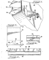
- Figure 1 shows, in perspective, the discharge end portion of a typical conveyor belt 20 having an'upper or delivery run 22 and a lower or return run 24, the belt being trained about a drum or roller 26 conventionally carried in a frame (not shown) within a housing 28.
- the housing is provided with an access door 30 which allows the operator to inspect the belt cleaning operation.
- a belt cleaner assembly 32 is provided consisting of a support 34 which.is disposed below and substantially transverse to the direction of travel of the return run 24, as indicated by the arrow.
- Figures land 2 illustrate the support 34 as being a circular shaft, any of a number of commonly used support members could be substituted for the circular shaft and operate within the scope of the present invention.
- Carried on the shaft 34 is a radially upstanding flange 36 which defines a plurality of connector apertures 38, the purpose for which will become apparent. If a flat bar or plate were used as a support member, no flange would be necessary.
- the apertures 38 would be formed directly into the bar.
- the apertures 38 include a slot section 40 and at the lower end a generally circular section 42.
- the arrangement of the cross-shaft 34, flange 36, and connectors 38 are best shown in Figure 2.
- the aperture 38 is illustrated generally in the form of a keyhole, any of a number of connector apertures of different shape could be substituted to achieve the same result.
- FIG 3 illustrates and describes a doctor blade 44 incorporating the features of the present invention.
- the doctor blade 44 as shown in Figures 3 through 6, has a triangularly shaped cross-section and is formed of an elastomeric material. Satisfactory results have been achieved by molding the doctor blade of 90 durometer urethane which exhibits low "compression set" qualities.
- the doctor blade 44 includes opposed faces 46 and 48 which are connected at the upper end by an inclined section 50 terminating in a point or edge 52.
- the edge 52 contacts the lower run 24 of the conveyor belt and effects the cleaning-operation.
- Metallic or non-metallic elements can be embedded into the cleaning portion of the blade, as well as to the face, in either the doctor blade or the arm and blade embodiment.
- One example would be ceramic beads embedded into the edge 52 or tungsten carbide sheets affixed against the face 46.
- a groove 54 is formed which extends laterally through the lower end of the blade such that a pair of legs 56, 58 are defined, one disposed on each side of the slot 54.
- Locking means are provided consisting of a downwardly extending lug 60 which is formed to include a neck section 62 and a generally circular bulb section 64.
- the lug 60 is adapted to matingly engage the connector 38' so that the bulb 64 is disposed within the circular section 42 and the neck section 62 lies within the slot section 40.
- Such a connecting arrangement of locking means and connector releasably locks the doctor blade 44 to the support member 34 so as to prevent linear movement of the blade 44 along the support member 34 and holds the blade in position for cleaning the conveyor belt.
- the aperture 38 is formed of a different shape than illustrated in Figure 2,-then the lug 60 must be shaped so as to matingly engage the aperture.
- the arm and blade embodiment of the present invention is disclosed in Figures 6 through 8.
- This embodiment includes an arm 66, shown as triangular in cross-section, integrally formed with a blade 68, both the arm and the blade being formed of elastomeric materials.
- Acceptable results have been achieved when both the arm and blade are molded of the same 90 durometer urethane, but it is also within the scope of the present invention to mold the unit as an integral part in which the arm 66 comsists of 60 durometer urethane, the blade 68 of 90 durometer urethane, and the fastening area between the arm and blade of 80 durometer urethane.
- the parts could also be made of dissimilar materials, for example, rubber, nylon, and urethane, and bonded together as an integral unit. Any of a number of plastics or rubbers, which exhibit the appropriate resilient tendencies, could be utilized to form the integral arm and blade element.
- Locking means 70 are formed on the arm 66 toward the end opposite the blade 68.
- the locking means 70 consist of a generally circular section 72 and a narrower neck section 74 disposed within an opening 76 formed between the arm 66 and a head section 78.
- the head 78 is generally of rectangular configuration.
- A-web 80 is shown connecting the blade 68 to the arm 66 and provides additional support against undue flexing of the arm with respect to the blade.
- an arm could be formed having a hollow internal chamber capable of being fitted with different inserts to change the spring rate or flexibility of the arm.
- the insert (not shown) could be either metallic or non-metallic.
- the locking means 70 is arranged to be connected to the connectors 38 of the support shaft 34 so that the circular section 72 lies within the circular section 42 and the neck section 74 lies within the glove section 40.
- Such an arrangement releasably locks the arm and blade to the shaft 34 and prevents linear movement of the arm and blade along the support member and holds the blade in position for cleaning the conveyor belt.
- a reversal of elements so as to make the male connector formed on the support and the female locking means formed on the arm is also considered within the scope of the present invention.
- the arm and blade unit is flexible, it is able to absorb shock due to impact throughout the unit rather than at specific flexible connections, as, for example, the spring arrangement in prior art torsion arm cleaners.
- This advantage allows the construction of a support frame of lighter, non-metallic materials, such as fiberglass. This, in turn, results in a totally corrosion resistant belt cleaner with no corrosion-prone sub-parts such as fasteners.
- the constant flexing also helps prevent build-up on the arms and blades.
- a plurality of doctor blades 44 are snap fit through the connections previously described into the flange 36 on shaft.34.
- the shaft is then raised by an adjustment mechanism (not shown) so that the doctor blades 44 and particularly the edge 52 engage the lower run 24 of the conveyor belt for cleaning. As the edge 52 wears, the shaft can be adjusted upwardly.
- the shaft is lowered and slid linearly out of the housing 28 providing access of the operator to the cleaner blades.
- the old blades 44 can be pried from the flange 36 and new blades snap fit into the flange with the tap of a hammer. Thus, replacement is accomplished without the use of any fasteners or special tools.
- the present invention eliminates this possibility and- provides for easy replacement of the belt cleaner blades.
- the worn blade can be reconstructed by remolding the worn portion of the blade back onto the original remaining part.
- the operation of the arm and blade cleaner is similar to that described for the doctor blade arrangement, but additional advantages of this embodiment exist.
- the arm 66 and the blade 68 are both formed of a resilient, elastomeric material, such a construction allows the blade to rotate about the central axis of the arm in a limited fashion so as to insure proper alignment between the blade and the belt being cleaned. If, for any reason, there is some initial misalignment between belt and blade when the shaft is rotated to exert force, the blade will inherently align itself with the belt due to the resilient nature of both the arm and the blade and their connection with each other.
- the shaft 34 is then rotated by the- handle, as shown in Figure 1, to secure contact between the blade and the return run 24.
- the blade 68 is disposed generally perpendicular to the central axis of the belt 24.
- this arrangement may be varied so that the blade 68 can assume a 90° angle with respect to the belt, as shown in Figure 6, or an acute angle Or an obtuse angle depending upon the desired arrangement.
- the shaft can, however, be incrementally adjusted to vary the angle with increasing rotation resulting in a general increase in the angle between the blade and the belt.
- the initial angle between blade and belt is an acute angle
- additional rotation of the shaft can change the angle from acute to perpendicular, with further rotation resulting in a change in the angle from perpendicular to obtuse.
- the same result would follow if the support were arranged for vertical adjustment.
- the ability to effect such incremental adjustment of the angle between the blade and the arm is of great advantage.
- the present arrangement in either embodiment, provides a conveyor belt cleaner with sufficient flexibility so as to prevent damage to the belt from the cleaner blade due to reversing belt operation, over-wear, over-adjustment, or sparking. It also provides an arrangement which utilizes non-metallic cleaner blades which offer greater safety if, for some reason, the blade fails or becomes disconnected and falls into the product stream.
Abstract
Description
- This invention relates to a conveyor belt cleaning arrangement comprising a linear support member disposed transverse to the direction of conveyor belt travel, and one or more belt cleaner blades formed of elastomeric material and detachably mountable on the support member.
- It has been known in the art to provide conveyor belt cleaners in which a transversely disposed cross-shaft provides a support for individually mounted belt cleaner blades of either the doctor blade or arm and blade type. Generally the blades are mounted by means of fasteners to mounting members disposed on the cross- shafts. When the blades wear beyond certain limits, the fasteners are removed and the blades are replaced. This type arrangement is shown in patents 4,098,394, . 3,598,231, 2,794,540, 1,975,591, 3,504,780 and 3,342,312.
- Other arrangements have attempted to provide for removal and replacement of cleaner blades without the use of fasteners. Some examples are shown in Patents 3,999,649, 4,131,194, 4,202,437, amd 4,265,358.
- Still others have recognized the advantages of a belt cleaner arrangement in which the arm and blade are formed as an integral unit, as shown in Patents 897,955 and 2,227,776.
- Other arrangements of interest are shown in Patents 4,328,888, 3,913,728, and 3,952,863.
- None of the prior art, however, discloses a belt cleaner-arrangement which provides the advantages of the present device.
- A conveyor belt cleaning arrangement according to the invention is characterised in that the support member defines a plurality of connector means adapted to locate and position individual belt cleaner blades, and each said blade includes locking means adapted to coact with said connector means to releasably lock said blade to said support member so as to prevent linear movement of said blade along said support member and to hold said blade in position for cleaning said conveyor belt.
- According to one preferred embodiment of the invention a doctor blade formed of a resilient,elastomeric material can be snap fit into locking association with the transverse support without the need for fasteners which are time consuming and can become lost. In another arm and blade embodiment of the invention, the arm and the blade are integrally formed as a single unit of resilient, elastomeric material, and a snap fit connector is provided at the end of the arm opposite the blade to secure the unit to the support. Such an arrangement allows the blade to rotate about the central axis of the arm to give better alignment with the belt. Due to the resilience of the arm and blade, the pressure applied by rotation of the transverse support can cause the angle of the blade with respect to the belt to be incrementally adjusted with the ability to go from a negative angle to a positive angle depending upon the particular circumstances of the environmental conditions.
- A full understanding of the invention will be had from the following detailed description which is given with reference to the accompanying drawings, wherein;
- Figure 1 is a perspective view showing the belt cleaning arrangement in operation.
- Figure 2 is a front view of the transverse support member with the cleaner blades removed.
- Figure 3 is a front view of a doctor blade removed from the transverse support member incorporating the features of the present invention.
- Figure 4 is a bottom view of the doctor blade taken along the lines 4-4 of Figure 3.
- Figure 5 is a side view of the doctor blade taken along the lines 5-5 of Figure 3.
- Figure 6 is a side view of the arm and blade' embodiment of the present invention removed from the transverse support member.
- Figure 7 is a rear view of the arm and blade taken along the lines 7-7 of Figure 6.
- Figure 8 is a top view of the arm and blade member taken along the lines 8-8 of Figure 7.
- Figure 1 shows, in perspective, the discharge end portion of a
typical conveyor belt 20 having an'upper or delivery run 22 and a lower or return run 24, the belt being trained about a drum orroller 26 conventionally carried in a frame (not shown) within ahousing 28. The housing is provided with anaccess door 30 which allows the operator to inspect the belt cleaning operation. - A
belt cleaner assembly 32 is provided consisting of asupport 34 which.is disposed below and substantially transverse to the direction of travel of thereturn run 24, as indicated by the arrow. Although Figures land 2 illustrate thesupport 34 as being a circular shaft, any of a number of commonly used support members could be substituted for the circular shaft and operate within the scope of the present invention. Carried on theshaft 34 is a radiallyupstanding flange 36 which defines a plurality ofconnector apertures 38, the purpose for which will become apparent. If a flat bar or plate were used as a support member, no flange would be necessary. Theapertures 38 would be formed directly into the bar. Theapertures 38 include aslot section 40 and at the lower end a generallycircular section 42. The arrangement of thecross-shaft 34,flange 36, andconnectors 38 are best shown in Figure 2. Although theaperture 38 is illustrated generally in the form of a keyhole, any of a number of connector apertures of different shape could be substituted to achieve the same result. - Two different embodiments of the present invention are disclosed herein. One embodiment will be referred to as the "doctor blade" arrangement, and is shown in Figures 3, 4, and 5. The other embodiment is referred to as the "arm and blade* arrangement and is best shown in Figures 6, 7, and 8. Either or both of these embodiments can be interchangeably used in a single belt cleaning arrangement.
- Figure 3 illustrates and describes a
doctor blade 44 incorporating the features of the present invention. Thedoctor blade 44, as shown in Figures 3 through 6, has a triangularly shaped cross-section and is formed of an elastomeric material. Satisfactory results have been achieved by molding the doctor blade of 90 durometer urethane which exhibits low "compression set" qualities. Thedoctor blade 44 includesopposed faces inclined section 50 terminating in a point oredge 52. Theedge 52 contacts thelower run 24 of the conveyor belt and effects the cleaning-operation. Metallic or non-metallic elements (not shown) can be embedded into the cleaning portion of the blade, as well as to the face, in either the doctor blade or the arm and blade embodiment. One example would be ceramic beads embedded into theedge 52 or tungsten carbide sheets affixed against theface 46. - At the lower end of the doctor blade 44 a
groove 54 is formed which extends laterally through the lower end of the blade such that a pair oflegs slot 54. Locking means are provided consisting of a downwardly extendinglug 60 which is formed to include aneck section 62 and a generallycircular bulb section 64. - It will be seen that the
lug 60 is adapted to matingly engage the connector 38' so that thebulb 64 is disposed within thecircular section 42 and theneck section 62 lies within theslot section 40. Such a connecting arrangement of locking means and connector releasably locks thedoctor blade 44 to thesupport member 34 so as to prevent linear movement of theblade 44 along thesupport member 34 and holds the blade in position for cleaning the conveyor belt. Obviously, if theaperture 38 is formed of a different shape than illustrated in Figure 2,-then thelug 60 must be shaped so as to matingly engage the aperture. It should also be apparent that a mirror image reversal of elements such that theaperture 38 is formed in the cleaner blade and thelug 60 is formed on the support member would also be operative and such an-arrangement-is considered-to be within the scope of the present arrangement. - The arm and blade embodiment of the present invention is disclosed in Figures 6 through 8. This embodiment includes an
arm 66, shown as triangular in cross-section, integrally formed with ablade 68, both the arm and the blade being formed of elastomeric materials. Acceptable results have been achieved when both the arm and blade are molded of the same 90 durometer urethane, but it is also within the scope of the present invention to mold the unit as an integral part in which thearm 66 comsists of 60 durometer urethane, theblade 68 of 90 durometer urethane, and the fastening area between the arm and blade of 80 durometer urethane. Conceivably the parts could also be made of dissimilar materials, for example, rubber, nylon, and urethane, and bonded together as an integral unit. Any of a number of plastics or rubbers, which exhibit the appropriate resilient tendencies, could be utilized to form the integral arm and blade element. - Locking means 70 are formed on the
arm 66 toward the end opposite theblade 68. The locking means 70 consist of a generallycircular section 72 and anarrower neck section 74 disposed within anopening 76 formed between thearm 66 and ahead section 78. Thehead 78 is generally of rectangular configuration. A-web 80 is shown connecting theblade 68 to thearm 66 and provides additional support against undue flexing of the arm with respect to the blade. - It is also contemplated that an arm could be formed having a hollow internal chamber capable of being fitted with different inserts to change the spring rate or flexibility of the arm. The insert (not shown) could be either metallic or non-metallic.
- As can readily be seen, the locking means 70 is arranged to be connected to the
connectors 38 of thesupport shaft 34 so that thecircular section 72 lies within thecircular section 42 and theneck section 74 lies within theglove section 40. Such an arrangement releasably locks the arm and blade to theshaft 34 and prevents linear movement of the arm and blade along the support member and holds the blade in position for cleaning the conveyor belt. As previously discussed, with respect to the doctor blade embodiment, a reversal of elements so as to make the male connector formed on the support and the female locking means formed on the arm is also considered within the scope of the present invention. - Since the arm and blade unit is flexible, it is able to absorb shock due to impact throughout the unit rather than at specific flexible connections, as, for example, the spring arrangement in prior art torsion arm cleaners. This advantage allows the construction of a support frame of lighter, non-metallic materials, such as fiberglass. This, in turn, results in a totally corrosion resistant belt cleaner with no corrosion-prone sub-parts such as fasteners. The constant flexing also helps prevent build-up on the arms and blades.
- In the operation of the doctor blade arrangement, a plurality of
doctor blades 44 are snap fit through the connections previously described into theflange 36 on shaft.34. The shaft is then raised by an adjustment mechanism (not shown) so that thedoctor blades 44 and particularly theedge 52 engage thelower run 24 of the conveyor belt for cleaning. As theedge 52 wears, the shaft can be adjusted upwardly. When replacement of theblades 44 is desired, the shaft is lowered and slid linearly out of thehousing 28 providing access of the operator to the cleaner blades. Theold blades 44 can be pried from theflange 36 and new blades snap fit into the flange with the tap of a hammer. Thus, replacement is accomplished without the use of any fasteners or special tools. It is common experience in the maintenance of the belt cleaning arrangements that where fasteners are used, they can easily become lost during the replacement operation. The present invention eliminates this possibility and- provides for easy replacement of the belt cleaner blades. The worn blade can be reconstructed by remolding the worn portion of the blade back onto the original remaining part. - The operation of the arm and blade cleaner is similar to that described for the doctor blade arrangement, but additional advantages of this embodiment exist. Since the
arm 66 and theblade 68 are both formed of a resilient, elastomeric material, such a construction allows the blade to rotate about the central axis of the arm in a limited fashion so as to insure proper alignment between the blade and the belt being cleaned. If, for any reason, there is some initial misalignment between belt and blade when the shaft is rotated to exert force, the blade will inherently align itself with the belt due to the resilient nature of both the arm and the blade and their connection with each other. - An additional advantage is found in the arm and blade embodiment. When the
arms 66 are connected to theflange 36, theshaft 34 is then rotated by the- handle, as shown in Figure 1, to secure contact between the blade and thereturn run 24. As shown in Figure 6, theblade 68 is disposed generally perpendicular to the central axis of thebelt 24. Depending upon the particular environment in which the belt cleaner is designed to operate, this arrangement may be varied so that theblade 68 can assume a 90° angle with respect to the belt, as shown in Figure 6, or an acute angle Or an obtuse angle depending upon the desired arrangement. The shaft can, however, be incrementally adjusted to vary the angle with increasing rotation resulting in a general increase in the angle between the blade and the belt. If, for example, the initial angle between blade and belt is an acute angle, additional rotation of the shaft can change the angle from acute to perpendicular, with further rotation resulting in a change in the angle from perpendicular to obtuse. The same result would follow if the support were arranged for vertical adjustment. The ability to effect such incremental adjustment of the angle between the blade and the arm is of great advantage. - The present arrangement, in either embodiment, provides a conveyor belt cleaner with sufficient flexibility so as to prevent damage to the belt from the cleaner blade due to reversing belt operation, over-wear, over-adjustment, or sparking. It also provides an arrangement which utilizes non-metallic cleaner blades which offer greater safety if, for some reason, the blade fails or becomes disconnected and falls into the product stream.
- Various features of the invention have been particularly shown and described in connection with the illustrated embodiments of the invention, however, it must be understood that these particular arrangements merely illustrate and that the invention is to be given its fullest interpretation within the terms of the appended claims.
Claims (8)
Priority Applications (1)
| Application Number | Priority Date | Filing Date | Title |
|---|---|---|---|
| AT84304745T ATE30894T1 (en) | 1984-02-13 | 1984-07-11 | CLEANING DEVICE FOR CONVEYOR BELTS. |
Applications Claiming Priority (2)
| Application Number | Priority Date | Filing Date | Title |
|---|---|---|---|
| US06/579,707 US4598823A (en) | 1984-02-13 | 1984-02-13 | Conveyor belt cleaner |
| US579707 | 1984-02-13 |
Publications (2)
| Publication Number | Publication Date |
|---|---|
| EP0153527A1 true EP0153527A1 (en) | 1985-09-04 |
| EP0153527B1 EP0153527B1 (en) | 1987-11-19 |
Family
ID=24318017
Family Applications (1)
| Application Number | Title | Priority Date | Filing Date |
|---|---|---|---|
| EP84304745A Expired EP0153527B1 (en) | 1984-02-13 | 1984-07-11 | Conveyor belt cleaner |
Country Status (17)
| Country | Link |
|---|---|
| US (1) | US4598823A (en) |
| EP (1) | EP0153527B1 (en) |
| JP (2) | JPS60171917A (en) |
| KR (1) | KR880002460B1 (en) |
| AT (1) | ATE30894T1 (en) |
| AU (1) | AU567175B2 (en) |
| BR (1) | BR8500586A (en) |
| CA (1) | CA1228830A (en) |
| DE (1) | DE3467557D1 (en) |
| DK (1) | DK158341C (en) |
| ES (1) | ES540324A0 (en) |
| FI (1) | FI76043C (en) |
| GR (1) | GR850389B (en) |
| MX (1) | MX160468A (en) |
| NO (1) | NO161055C (en) |
| NZ (1) | NZ211103A (en) |
| ZA (1) | ZA845249B (en) |
Cited By (3)
| Publication number | Priority date | Publication date | Assignee | Title |
|---|---|---|---|---|
| EP0328171A1 (en) * | 1988-02-10 | 1989-08-16 | Technic Gum | Mounting of scraper blades for conveyor belts |
| EP0583731A1 (en) * | 1992-08-14 | 1994-02-23 | Gordon Belt Scrapers, Inc. | Primary belt cleaners and blades |
| EP2551220A1 (en) * | 2011-07-28 | 2013-01-30 | Martin Engineering Company | Conveyer belt scraper assembly comprising scraper members that are clamped together and method pertaining to the same |
Families Citing this family (34)
| Publication number | Priority date | Publication date | Assignee | Title |
|---|---|---|---|---|
| DE3517782A1 (en) * | 1985-05-17 | 1986-11-20 | Mannesmann AG, 4000 Düsseldorf | CLEANER FOR A DRUM |
| DE3644934A1 (en) * | 1986-03-12 | 1988-04-28 | Vsr Eng Foerdertechnik | Mounting apparatus for stripper apparatus for cleaning conveyor belts |
| US4779716A (en) * | 1986-08-22 | 1988-10-25 | Gordon Balt Scrapers, Inc. | Conveyor belt cleaner |
| GB2201136B (en) * | 1987-02-20 | 1990-07-04 | Dohmeier Hans Otto | Conveyor belt scraper |
| US4825997A (en) * | 1987-10-09 | 1989-05-02 | Martin Engineering Co. | Pneumatically actuated tensioning arrangement for conveyor belt cleaner |
| CA1284307C (en) * | 1988-03-03 | 1991-05-21 | Normand Morin | Conveyer belt scraper |
| AU603538B3 (en) * | 1989-03-31 | 1990-09-26 | Belle Banne Flexco Pty Limited | Conveyor belt cleaning arrangement |
| US4962845A (en) * | 1989-07-26 | 1990-10-16 | Asgco Manufacturing, Inc. | Conveyer belt scraping apparatus |
| US5222588A (en) * | 1991-01-29 | 1993-06-29 | Gordon Belt Scrapers, Inc. | Secondary conveyor belt cleaners |
| WO1993004959A1 (en) * | 1991-08-30 | 1993-03-18 | Dolan Troy D | Method and apparatus for cleaning conveyor belts |
| US5301797A (en) * | 1993-01-29 | 1994-04-12 | J & H Equipment | Torque arm system for conveyor belt cleaners |
| AUPM872694A0 (en) * | 1994-10-11 | 1994-11-03 | Mato Australia Pty Limited | Scraper blade for belt conveyors |
| US5799776A (en) * | 1995-10-27 | 1998-09-01 | Dolan; Troy D. | Method and apparatus for adjusting pressure on scraper blades |
| US5979638A (en) * | 1997-08-21 | 1999-11-09 | Argonics, Inc. | Conveyor belt wiper blade |
| US6439373B1 (en) | 1998-11-09 | 2002-08-27 | Martin Engineering Company | Constant angle and pressure conveyor belt cleaner and tensioning arrangement |
| US6986418B2 (en) * | 1998-12-10 | 2006-01-17 | Martin Engineering Company | Conveyor belt cleaner scraper blade with sensor and control system therefor |
| US6374990B1 (en) | 1998-12-10 | 2002-04-23 | Martin Engineering Company | Conveyor belt cleaner scraper blade with sensor |
| US6591969B2 (en) * | 1998-12-10 | 2003-07-15 | Martin Engineering Company | Conveyor belt cleaner scraper blade with sensor and method of manufacture |
| US6401911B1 (en) | 1999-01-15 | 2002-06-11 | Martin Engineering Company | Differential wear conveyor belt scraper blade |
| US6354428B1 (en) | 1999-09-09 | 2002-03-12 | Asgco Manufacturing, Inc. | Conveyor belt scraping apparatus |
| US6948609B2 (en) * | 2000-03-23 | 2005-09-27 | Asgco Manufacturing, Inc. | Light duty belt cleaning system |
| US6926133B2 (en) * | 2003-03-27 | 2005-08-09 | Flexible Steel Lacing Company | Scraper blade for conveyor belts |
| US6968940B2 (en) * | 2003-12-16 | 2005-11-29 | Argonics, Inc. | Universal mount for a cleaning blade for a conveying belt |
| US7308980B2 (en) * | 2004-11-24 | 2007-12-18 | Martin Engineering Company | Method for distributing a conveyor belt cleaner |
| US7367443B2 (en) * | 2004-11-24 | 2008-05-06 | Martin Engineering Company | Conveyor belt cleaner system and method of manufacturing same |
| JP4012208B2 (en) * | 2005-04-12 | 2007-11-21 | 日本通商株式会社 | Belt cleaner device |
| US7549532B2 (en) * | 2006-07-21 | 2009-06-23 | Nelson Williams Linings, Inc. | Conveyor belt cleaning system and mounting method |
| US8336702B2 (en) | 2009-04-27 | 2012-12-25 | Asgco Manufacturing, Inc. | Reversible tensioning device, as for a conveyor |
| US8875870B2 (en) | 2011-03-31 | 2014-11-04 | Benetech, Inc. | Conveyor belt cleaner scraper blade and assembly |
| AT511583B1 (en) | 2011-09-28 | 2013-01-15 | Hoessl Gmbh | SPREADER FOR A CONVEYOR BELT |
| JP6589426B2 (en) * | 2015-07-15 | 2019-10-16 | 日本製鉄株式会社 | Belt cleaner device |
| WO2021035041A1 (en) | 2019-08-20 | 2021-02-25 | Benetech, Inc. | Enclosure and dust capture and reclamation system and assembly for a traditional roller conveyor |
| US20230002170A1 (en) * | 2020-08-20 | 2023-01-05 | Ess Engineering Services & Supplies Pty Limited | Conveyor Belt Cleaner |
| US11919719B2 (en) | 2021-05-13 | 2024-03-05 | Benetech, Inc. | Drop and slide out idler assembly |
Citations (2)
| Publication number | Priority date | Publication date | Assignee | Title |
|---|---|---|---|---|
| US4105109A (en) * | 1977-03-04 | 1978-08-08 | Schultz John J | Scraper cleaning apparatus for endless conveyor belt |
| GB2055730A (en) * | 1979-08-15 | 1981-03-11 | Fenner Co Ltd J H | Conveyor belt scraper device |
Family Cites Families (12)
| Publication number | Priority date | Publication date | Assignee | Title |
|---|---|---|---|---|
| US1975591A (en) * | 1932-11-15 | 1934-10-02 | Adamson Stephens Mfg Co | Belt cleaner |
| US3342312A (en) * | 1966-02-10 | 1967-09-19 | Robert C Reiter | Conveyor belt cleaner |
| JPS5636628B2 (en) * | 1971-11-19 | 1981-08-25 | ||
| BE793561A (en) * | 1971-12-30 | 1973-04-16 | Western Electric Co | ELECTROLUMINESCENT DISPLAY DEVICE |
| US4098394A (en) * | 1976-11-22 | 1978-07-04 | Martin Engineering Company | Ratchet tensioner for belt cleaners |
| SE423703B (en) * | 1976-12-17 | 1982-05-24 | Trelleborg Ab | ENDLESS TRANSPORT BELT REMOVAL |
| US4202437A (en) * | 1977-10-06 | 1980-05-13 | Gordon James R | Scraper assembly for a conveyor belt |
| FR2421825A1 (en) * | 1978-04-07 | 1979-11-02 | Fives Cail Babcock | BELT CLEANING DEVICE FOR AN ENDLESS BELT CONVEYOR |
| US4269301A (en) * | 1979-10-22 | 1981-05-26 | Gibbs Alfred S | Conveyor belt scraper system |
| US4359150A (en) * | 1980-05-09 | 1982-11-16 | Martin Engineering Company | Conveyor belt cleaner |
| JPS5751217U (en) * | 1980-09-09 | 1982-03-24 | ||
| US4389936A (en) * | 1980-11-18 | 1983-06-28 | Precision Screen Machines, Inc. | Cleaning attachment for screen printer |
-
1984
- 1984-02-13 US US06/579,707 patent/US4598823A/en not_active Expired - Lifetime
- 1984-06-06 CA CA000455983A patent/CA1228830A/en not_active Expired
- 1984-07-06 ZA ZA845249A patent/ZA845249B/en unknown
- 1984-07-09 NO NO842793A patent/NO161055C/en unknown
- 1984-07-10 AU AU30444/84A patent/AU567175B2/en not_active Ceased
- 1984-07-11 EP EP84304745A patent/EP0153527B1/en not_active Expired
- 1984-07-11 AT AT84304745T patent/ATE30894T1/en not_active IP Right Cessation
- 1984-07-11 DE DE8484304745T patent/DE3467557D1/en not_active Expired
- 1984-07-16 MX MX202031A patent/MX160468A/en unknown
- 1984-07-30 DK DK370384A patent/DK158341C/en not_active IP Right Cessation
- 1984-07-31 JP JP59159459A patent/JPS60171917A/en active Pending
- 1984-10-19 FI FI844139A patent/FI76043C/en not_active IP Right Cessation
-
1985
- 1985-02-02 KR KR1019850000668A patent/KR880002460B1/en not_active IP Right Cessation
- 1985-02-08 BR BR8500586A patent/BR8500586A/en not_active IP Right Cessation
- 1985-02-12 ES ES540324A patent/ES540324A0/en active Granted
- 1985-02-12 NZ NZ211103A patent/NZ211103A/en unknown
- 1985-02-13 GR GR850389A patent/GR850389B/el unknown
-
1988
- 1988-08-12 JP JP1988106932U patent/JPS6432820U/ja active Pending
Patent Citations (2)
| Publication number | Priority date | Publication date | Assignee | Title |
|---|---|---|---|---|
| US4105109A (en) * | 1977-03-04 | 1978-08-08 | Schultz John J | Scraper cleaning apparatus for endless conveyor belt |
| GB2055730A (en) * | 1979-08-15 | 1981-03-11 | Fenner Co Ltd J H | Conveyor belt scraper device |
Cited By (5)
| Publication number | Priority date | Publication date | Assignee | Title |
|---|---|---|---|---|
| EP0328171A1 (en) * | 1988-02-10 | 1989-08-16 | Technic Gum | Mounting of scraper blades for conveyor belts |
| BE1002933A3 (en) * | 1988-02-10 | 1991-09-03 | Technic Gum Sa | MOUNTING OF SCRAPER BLADES FOR THE CLEANING OF A CONVEYOR BELT. |
| EP0583731A1 (en) * | 1992-08-14 | 1994-02-23 | Gordon Belt Scrapers, Inc. | Primary belt cleaners and blades |
| EP2551220A1 (en) * | 2011-07-28 | 2013-01-30 | Martin Engineering Company | Conveyer belt scraper assembly comprising scraper members that are clamped together and method pertaining to the same |
| US8393459B2 (en) | 2011-07-28 | 2013-03-12 | Martin Engineering Company | Conveyor belt scraper assembly comprising scraper members that are clamped together and method pertaining to the same |
Also Published As
| Publication number | Publication date |
|---|---|
| NO842793L (en) | 1985-08-14 |
| EP0153527B1 (en) | 1987-11-19 |
| DK158341B (en) | 1990-05-07 |
| FI76043C (en) | 1988-09-09 |
| DK158341C (en) | 1990-11-19 |
| GR850389B (en) | 1985-06-14 |
| DE3467557D1 (en) | 1987-12-23 |
| ATE30894T1 (en) | 1987-12-15 |
| NO161055C (en) | 1989-06-28 |
| DK370384D0 (en) | 1984-07-30 |
| CA1228830A (en) | 1987-11-03 |
| FI844139A0 (en) | 1984-10-19 |
| ZA845249B (en) | 1985-02-27 |
| ES8602451A1 (en) | 1985-12-01 |
| NO161055B (en) | 1989-03-20 |
| ES540324A0 (en) | 1985-12-01 |
| AU567175B2 (en) | 1987-11-12 |
| US4598823A (en) | 1986-07-08 |
| BR8500586A (en) | 1985-09-24 |
| KR850005816A (en) | 1985-09-26 |
| MX160468A (en) | 1990-03-08 |
| FI844139L (en) | 1985-08-14 |
| AU3044484A (en) | 1985-08-22 |
| JPS60171917A (en) | 1985-09-05 |
| JPS6432820U (en) | 1989-03-01 |
| FI76043B (en) | 1988-05-31 |
| NZ211103A (en) | 1986-07-11 |
| DK370384A (en) | 1985-08-14 |
| KR880002460B1 (en) | 1988-11-14 |
Similar Documents
| Publication | Publication Date | Title |
|---|---|---|
| US4598823A (en) | Conveyor belt cleaner | |
| US4643293A (en) | Conveyor belt cleaner | |
| US6926133B2 (en) | Scraper blade for conveyor belts | |
| US6401911B1 (en) | Differential wear conveyor belt scraper blade | |
| EP1193197B1 (en) | Conveyor belt cleaner | |
| AU725775B2 (en) | Conveyor belt scraper blade | |
| EP0583731B1 (en) | Primary belt cleaners and blades | |
| US4854443A (en) | Conveyor belt cleaner | |
| CA1166181A (en) | Conveyer belt cleaner | |
| AU665166B2 (en) | Bucket base edge protector assembly | |
| CA1150013A (en) | Device for connecting a wiper blade holder to a wiper arm | |
| US4779716A (en) | Conveyor belt cleaner | |
| US20020125106A1 (en) | Conveyor belt cleaning system | |
| US6095318A (en) | Conveyor scraper and mounting of scraper blade | |
| WO2003084309A3 (en) | Easy change replacement mower blade | |
| US5583548A (en) | Bi-directional wiper for ink jet printhead and method of operation | |
| AU758057B2 (en) | A connection for two ends of a conveyor belt | |
| US3918214A (en) | Vibrating sander | |
| CA2060165C (en) | Conveyor belt cleaners | |
| US6981910B1 (en) | Throwing wheel assembly | |
| EP0208026A2 (en) | Adjustable sickle guard assembly | |
| CN219383847U (en) | Belt feeder head sweeper | |
| AU724505B3 (en) | Conveyor belt cleaning system | |
| AU766537B2 (en) | Improvements relating to conveyor scrapers |
Legal Events
| Date | Code | Title | Description |
|---|---|---|---|
| PUAI | Public reference made under article 153(3) epc to a published international application that has entered the european phase |
Free format text: ORIGINAL CODE: 0009012 |
|
| 17P | Request for examination filed |
Effective date: 19850425 |
|
| AK | Designated contracting states |
Designated state(s): AT BE CH DE FR GB IT LI LU NL SE |
|
| 17Q | First examination report despatched |
Effective date: 19860117 |
|
| GRAA | (expected) grant |
Free format text: ORIGINAL CODE: 0009210 |
|
| AK | Designated contracting states |
Kind code of ref document: B1 Designated state(s): AT BE CH DE FR GB IT LI LU NL SE |
|
| PG25 | Lapsed in a contracting state [announced via postgrant information from national office to epo] |
Ref country code: LI Effective date: 19871119 Ref country code: CH Effective date: 19871119 Ref country code: AT Effective date: 19871119 |
|
| REF | Corresponds to: |
Ref document number: 30894 Country of ref document: AT Date of ref document: 19871215 Kind code of ref document: T |
|
| ITF | It: translation for a ep patent filed |
Owner name: JACOBACCI & PERANI S.P.A. |
|
| REF | Corresponds to: |
Ref document number: 3467557 Country of ref document: DE Date of ref document: 19871223 |
|
| ET | Fr: translation filed | ||
| REG | Reference to a national code |
Ref country code: CH Ref legal event code: PL |
|
| PLBE | No opposition filed within time limit |
Free format text: ORIGINAL CODE: 0009261 |
|
| STAA | Information on the status of an ep patent application or granted ep patent |
Free format text: STATUS: NO OPPOSITION FILED WITHIN TIME LIMIT |
|
| 26N | No opposition filed | ||
| ITTA | It: last paid annual fee | ||
| EPTA | Lu: last paid annual fee | ||
| EAL | Se: european patent in force in sweden |
Ref document number: 84304745.7 |
|
| PGFP | Annual fee paid to national office [announced via postgrant information from national office to epo] |
Ref country code: NL Payment date: 19950727 Year of fee payment: 12 |
|
| PG25 | Lapsed in a contracting state [announced via postgrant information from national office to epo] |
Ref country code: NL Effective date: 19970201 |
|
| NLV4 | Nl: lapsed or anulled due to non-payment of the annual fee |
Effective date: 19970201 |
|
| PGFP | Annual fee paid to national office [announced via postgrant information from national office to epo] |
Ref country code: FR Payment date: 20010619 Year of fee payment: 18 |
|
| PGFP | Annual fee paid to national office [announced via postgrant information from national office to epo] |
Ref country code: LU Payment date: 20010629 Year of fee payment: 18 |
|
| PGFP | Annual fee paid to national office [announced via postgrant information from national office to epo] |
Ref country code: BE Payment date: 20010713 Year of fee payment: 18 |
|
| REG | Reference to a national code |
Ref country code: GB Ref legal event code: IF02 |
|
| PGFP | Annual fee paid to national office [announced via postgrant information from national office to epo] |
Ref country code: SE Payment date: 20020620 Year of fee payment: 19 |
|
| PGFP | Annual fee paid to national office [announced via postgrant information from national office to epo] |
Ref country code: GB Payment date: 20020703 Year of fee payment: 19 |
|
| PG25 | Lapsed in a contracting state [announced via postgrant information from national office to epo] |
Ref country code: LU Free format text: LAPSE BECAUSE OF NON-PAYMENT OF DUE FEES Effective date: 20020711 |
|
| PGFP | Annual fee paid to national office [announced via postgrant information from national office to epo] |
Ref country code: DE Payment date: 20020730 Year of fee payment: 19 |
|
| PG25 | Lapsed in a contracting state [announced via postgrant information from national office to epo] |
Ref country code: BE Free format text: LAPSE BECAUSE OF NON-PAYMENT OF DUE FEES Effective date: 20020731 |
|
| BERE | Be: lapsed |
Owner name: *MARTIN ENGINEERING CY Effective date: 20020731 |
|
| PG25 | Lapsed in a contracting state [announced via postgrant information from national office to epo] |
Ref country code: FR Free format text: LAPSE BECAUSE OF NON-PAYMENT OF DUE FEES Effective date: 20030331 |
|
| REG | Reference to a national code |
Ref country code: FR Ref legal event code: ST |
|
| PG25 | Lapsed in a contracting state [announced via postgrant information from national office to epo] |
Ref country code: GB Free format text: LAPSE BECAUSE OF NON-PAYMENT OF DUE FEES Effective date: 20030711 |
|
| PG25 | Lapsed in a contracting state [announced via postgrant information from national office to epo] |
Ref country code: SE Free format text: LAPSE BECAUSE OF NON-PAYMENT OF DUE FEES Effective date: 20030712 |
|
| PG25 | Lapsed in a contracting state [announced via postgrant information from national office to epo] |
Ref country code: DE Free format text: LAPSE BECAUSE OF NON-PAYMENT OF DUE FEES Effective date: 20040203 |
|
| EUG | Se: european patent has lapsed | ||
| GBPC | Gb: european patent ceased through non-payment of renewal fee |
Effective date: 20030711 |