EP0173513A2 - A hydraulic master cylinder assembly - Google Patents
A hydraulic master cylinder assembly Download PDFInfo
- Publication number
- EP0173513A2 EP0173513A2 EP85305785A EP85305785A EP0173513A2 EP 0173513 A2 EP0173513 A2 EP 0173513A2 EP 85305785 A EP85305785 A EP 85305785A EP 85305785 A EP85305785 A EP 85305785A EP 0173513 A2 EP0173513 A2 EP 0173513A2
- Authority
- EP
- European Patent Office
- Prior art keywords
- lever
- master cylinder
- assembly
- actuating
- actuating lever
- Prior art date
- Legal status (The legal status is an assumption and is not a legal conclusion. Google has not performed a legal analysis and makes no representation as to the accuracy of the status listed.)
- Granted
Links
Images


Classifications
-
- B—PERFORMING OPERATIONS; TRANSPORTING
- B60—VEHICLES IN GENERAL
- B60T—VEHICLE BRAKE CONTROL SYSTEMS OR PARTS THEREOF; BRAKE CONTROL SYSTEMS OR PARTS THEREOF, IN GENERAL; ARRANGEMENT OF BRAKING ELEMENTS ON VEHICLES IN GENERAL; PORTABLE DEVICES FOR PREVENTING UNWANTED MOVEMENT OF VEHICLES; VEHICLE MODIFICATIONS TO FACILITATE COOLING OF BRAKES
- B60T11/00—Transmitting braking action from initiating means to ultimate brake actuator without power assistance or drive or where such assistance or drive is irrelevant
- B60T11/10—Transmitting braking action from initiating means to ultimate brake actuator without power assistance or drive or where such assistance or drive is irrelevant transmitting by fluid means, e.g. hydraulic
- B60T11/16—Master control, e.g. master cylinders
- B60T11/165—Single master cylinders for pressurised systems
-
- B—PERFORMING OPERATIONS; TRANSPORTING
- B62—LAND VEHICLES FOR TRAVELLING OTHERWISE THAN ON RAILS
- B62L—BRAKES SPECIALLY ADAPTED FOR CYCLES
- B62L3/00—Brake-actuating mechanisms; Arrangements thereof
- B62L3/02—Brake-actuating mechanisms; Arrangements thereof for control by a hand lever
- B62L3/023—Brake-actuating mechanisms; Arrangements thereof for control by a hand lever acting on fluid pressure systems
Definitions
- This invention relates to hydraulic master cylinder assemblies and particularly but not exclusively to brake master cylinder assemblies for motorcycles.
- a hydraulic master cylinder comprising a hydraulic master cylinder and an actuating mechanism, the hydraulic master cylinder having a piston slidable in a bore in the body of the master cylinder, the actuator mechanism having a driver operated actuating lever operatively connected to the piston to effect axial movement thereof in response to driver operation of the actuating lever.
- a motorcycle racing team may well have a range of master cylinders of differing bore diameters for each motorcycle to suit different circuits and weather conditions and variations in rider technique.
- a hydraulic master cylinder assembly comprising a hydraulic master cylinder and an actuating mechanism, the hydraulic master cylinder having a body member defining a bore therein, and being adapted for attachment to part of a vehicle a piston slideably supported in the bore and having an input member for co-operation with part of the actuating mechanism, the actuating mechanism having a driver operated actuating lever and an operative connection to connect the actuating lever to the input member said operative connection including means for altering the travel ratio between the actuating lever and the input member.
- said operative connection may include a lever mechanism and the means for altering the travel ratio include an adjustable abutment.
- the lever mechanism includes a transfer lever interposed between the adjustable abutment member and the input member.
- the lever mechanism may be formed by the adjustable abutment member and the adjustable member will react directly against the input member.
- the master cylinder assembly of Figs 1 to 4 comprises a hydraulic master cylinder 11 and an actuating mechanism.
- the hydraulic master cylinder 11 has a body member 12 slideably supporting a piston 16 therein and is adapted by means of a slotted end portion 13 for attaching the master cylinder assembly upon the handlebar (not shown) of a motor cycle.
- An actuating lever 14 and a transfer lever 15 are pivoted upon the end portion 13 to connect the actuating lever 14 to the piston 16.
- the body member 12 defines a bore 18 having an outlet 19 at one end of the bore 18 to which a pipe or hose maybe connected by the screw-threaded aperture 20.
- a blind screw-threaded bore 21 is provided to co-operate with a bolt 22 securing the reservoir 17 to the body 11.
- Bypass and reservoir ports 23, 24 are provided to connect the bore 18 to the reservoir 17.
- the piston 16 has main and secondary cup seals 25, 26 and a blind bore 28 in one end in which a compression spring 27 is housed to bias the piston 16 away from the outlet 19 and an input member in the form of a wear resistent pad 50 at the other end.
- a guide pin 32 coaxial with the bore 28 and extending axially through the spring 27 is connected to the body 11 by a plate 30.
- the end portion 13 has a part-cylindrical central portion 31 the bore 29 of which is concentric with the bore 18 in the master cylinder portion 12, two parallel flanges 33, 34 each having a through hole 35, 36 in which a pivot pin 37 is secured, and a webbed base portion 38 having a bottom face 39 in which a part-cylindrical slot 40 is formed to co-operate with the handlebar.
- the end face 41 of the end portion 13 has a slot 42 formed in it into which the transfer lever 15 is located.
- the actuating lever 14 is pivotally connected by the pivot pin 37 to the end portion 13 and has a portion away from the pivotal connection that is contoured to provide a comfortable hand grip 55.
- a rod in the form of a set screw 47 is in threaded engagement with the actuating lever 14.
- the set screw 47 forms a movable abutment member and is locked into position by a locknut 48.
- a grub screw 49 is provided to adjust the resting position of the actuating lever 14.
- the transfer lever 15 is pivotally supported by a pivot pin 43 secured in the base portion 38 and has a pivot axis arranged to be substantially parallel to the pivot axis of the actuating lever 14.
- the transfer lever 15 has a convex abutment surface in the form of a lobe 44 for reaction against the pad 50 and a concave abutment surface in the form of the longitudinal groove 45 to co-operate with a part- spherical end portion 51 of the set screw 47.
- a driver or rider applies a force to the actuating lever 14 causing it to rotate about the pivot pin 37.
- the rotation of the actuating lever 14 causes the set screw 47 to react against the transfer lever 15 which rotates about the pivot pin 43.
- the lobe 44 transfers the load applied to the transfer lever 15 to the pad so thereby displacing the piston 16 to increase the hydraulic pressure in the hydraulic master cylinder 11.
- the travel ratio for the master cylinder assembly is the ratio of the linear movement of the piston 16 obtained for a specified linear displacement of a known point on the actuating lever 14.
- the known point is the effective position where the applied force acts.
- the travel ratio of the master cylinder assembly is adjustable by rotating the set screw 47 which will move axially thereby altering its position of contact with the transfer lever 15. If for example, the set screw 43 contacts the transfer lever 15 near to the pivot pin 43 then the travel ratio will be high as a small actuating lever 14 movement will produce a relatively large axial displacement of the piston 16.
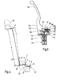
- Fig 4 there is shown in skeletal form the master cylinder assembly of Figs 1-3 showing in ghosted outline the transfer lever 15' the piston 16' and the actuating lever 14'.
- the master cylinder assembly of Fig 5 comprises a hydraulic master cylinder 111 and an actuating mechanism.
- the hydraulic master cylinder 111 has a body member 112 slideably supporting a pistonll6 therein and is adapted by means of an end portion 113 for attaching the master cylinder assembly to part of a vehicle (not shown).
- the actuating mechanism includes an actuating lever 14. a transfer lever 115 and a set screw 147.
- the end portion 113 pivotally supports the actuating lever 114 and the transfer lever 115 by means of two press fitted pivot pins 137 and 143 the pivot axes of which are substantially parallel to one another.
- the actuating lever 114 has a portion away from the pivot pin 137 that is contoured to provide a hand grip 155 and a flat abutment surface 156 for abutment with an adjustable abutment member interposed between the actuating lever 114 and the transfer lever 115.
- the set screw 147 and the transfer lever 115 form a lever mechanism between the actuating lever 119 and the piston 116.
- the adjustable abutment member is in the form of the set screw 147 threadably engaged with the transfer lever 115 and lockable into position by a locknut 148.
- the set screw has a disc shaped head 157, the outer peripheral surface of which is convex, and a screw-threaded shank 158.
- the end of the screw-threaded shank 158 away from the head 157 has a slot 159 in it into which a suitable tool can be fitted to rotate the set screw 147.
- the transfer lever 115 has a convex abutment surface in the form of the lobe 144 for co-operation with an input member of the master cylinder 112.
- the input member is in the form of a wear resistent pad 150 attached to an extension of the piston 116.
- Operation of the master cylinder assembly is substantially as described with reference to Figs 1 to 4 and the travel ratio can be similarly altered by moving the set screw 147. Any axial movement of the set screw 147 will have a two-fold effect on the travel ratio.
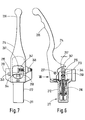
- the master cylinder assembly shown in Figs 6 and 7 is similar in many respects to that shown in Fig 1 to 4 and part similar to those described with respect to Figs 1 to 4 have the same reference numerals with the addition of 200.
- the master cylinder assembly comprises a hydraulic master cylinder 211 and an actuating mechanism.
- the hydraulic master cylinder 211 having a body member 212 and an end portion 213 for attaching the master cylinder assembly to part of a vehicle (not shown).
- the body member 212 defines a bore therein in which a piston 216 is slideably supported.
- The" actuating mechanism includes an actuating lever 214 a transfer lever 215 and a set screw 247.
- the end portion 213 pivotally supports the actuating lever 214 and the transfer lever 215 by means of two press-fitted pivot pins 237 and 243.
- the pivotal axis of the actuating lever 214 and the transfer lever 125 are perpendicularly arranged with respect to one another.
- the transfer lever 215 and the set screw 247 form a lever mechanism between the actuator lever 214 and the piston 216.
- the actuating lever 214 has a portion away from the pivot pin 237 that is contoured to provide a hand grip 255.
- the set screw 247 is in threaded engagement with the actuating lever 214 to provide an adjustable abutment member between the actuating and transfer levers 214 and 215.
- the set screw 247 is lockable in position by a lock nut 248 and has a disc shaped head 257 the outer peripheral surface of which is convex.
- the transfer lever 215 has a convex abutment surface in the form of a lobe 244 for co-operation with an input member of the master cylinder and a flat surface for abutment with the head 257.
- the input member of the master cylinder is in the form of a wear resistant pad 250 attached to an extension of the piston 216.
- a driver or rider applies a force to the actuating levet* 214 at or near the hand grip 255 causing the actuating lever 214 to rotate about the pivot pin 237.
- the rotation of the actuating lever 214 is transmitted to the transfer lever 215 by the set screw 247 causing the transfer lever 215 to rotate about the pivot pin 243.
- the movement of the transfer lever 215 is transmitted to the piston 216 through the abutment of the lobe 244 with the pad 250.
- the set screw 247 is rotated, thereby altering the distance between its position of abutment with the transfer lever 215 and the pivotal axis of the transfer lever 215.
- the longitudinal axis of the set screw is substantially parallel to the pivotal axis of the actuating lever 214 and so no variation in the distance between the pivotal axis of the actuating lever 214 and the position of abutment of the set-screw 247 against the transfer lever 215 will occur when the set screw 247 is rotated to alter the travel ratio. Therefore, unlike the first and second embodiments previously described the change in travel ratio is due entirely to the variation in the distance of the position of abutment of the set screw 247 against the transfer lever 215 from the pivotal axis of the transfer lever 215.
- a fourth embodiment of the invention shown in Fig 8 the master cylinder assembly is substantially the same as that described with reference to Figs 1 to 4 and parts similar to those described with respect to Figs 1 to 4 have the same reference numerals with the addition of 300.
- the master cylinder assembly comprises a hydraulic master cylinder 311 and an actuating mechanism.
- the hydraulic master cylinder 311 has a body member 312 and an end portion 313 for attaching the master cylinder assembly to part of a vehicle (not shown).
- the body member 312 pivotally supports a press-fitted pivot pin 337.
- the actuating mechanism includes the actuating lever 314 and a set screw 347.
- the actuating lever 314 has a screw threaded boss portion 379 and a portion away from its pivotal axis that is contoured to provide a hand grip 355.
- the set screw 347 is threaded into the boss portion 379 to provide both a lever mechanism and a movable abutment member between the actuatin ⁇ lever 314 and the piston 316.
- the set screw 347 is lockable in position by a lock nut 348 and has a disc shaped head 357, the outer peripheral of which is convex.
- the head 357 of the set screw 347 abuts directly against a wear resistant pad 350 attached to an extension 370 of the piston 216.
- the pad 350 forms an input member of the master cylinder and has a flat face 371 for co-operation with the head 357 and a stem 372 used to attach the pad 350 to the extension 370.
- the travel ratio that is to say the ratio of actuating lever 314 movement to piston 316 movement can be seen to be equal to the ratio between the effective length of the actuating lever 314 and the distance of the position of abutment of the set screw 347 against the pad 350 from the pivotal axis of the actuating lever 314. Therefore, by axially moving the set screw 347 the displacement ratio can be altered as the distance of the position of abutment of the set screw 347 against the pad 350 will be changed with respect to the pivotal axis of the actuating lever 314.
- moveable abutment has been described as a set screw attached to the actuating lever or transfer lever any device which allows the position of abutment of the actuating lever with the transfer lever or piston could be used.
- the travel ratio can be adjusted without removing the master cylinder assembly from the vehicle.
Abstract
Description
- This invention relates to hydraulic master cylinder assemblies and particularly but not exclusively to brake master cylinder assemblies for motorcycles.
- It is known to provide a hydraulic master cylinder comprising a hydraulic master cylinder and an actuating mechanism, the hydraulic master cylinder having a piston slidable in a bore in the body of the master cylinder, the actuator mechanism having a driver operated actuating lever operatively connected to the piston to effect axial movement thereof in response to driver operation of the actuating lever.
- The large range of applications for hydraulic master cylinders requires the manufacturer to offer a range of master cylinders of differing bore diameters to accommodate variations in hydraulic system capacity. It is not economically viable to offer a different bore diameter to suit each specific application instead a range of master cylinders is offered in standard sizes. The fact that the ideal bore diameter is not available is not normally a serious drawback and a suitable compromise can often be found. If however, the master cylinder is to be used for a motorcycle braking system it is important that the bore diameter is as close as possible to the ideal size in order to obtain the highest possible efficiency.
- In the case of racing motorcycles it is important that the correct diameter master cylinder is used for each application. A motorcycle racing team may well have a range of master cylinders of differing bore diameters for each motorcycle to suit different circuits and weather conditions and variations in rider technique.
- It is an object of the invention to provide a master cylinder that can be adjusted to suit a particular installation.
- According to the invention there is provided a hydraulic master cylinder assembly comprising a hydraulic master cylinder and an actuating mechanism, the hydraulic master cylinder having a body member defining a bore therein, and being adapted for attachment to part of a vehicle a piston slideably supported in the bore and having an input member for co-operation with part of the actuating mechanism, the actuating mechanism having a driver operated actuating lever and an operative connection to connect the actuating lever to the input member said operative connection including means for altering the travel ratio between the actuating lever and the input member.
- Conveniently said operative connection may include a lever mechanism and the means for altering the travel ratio include an adjustable abutment.
- Preferably, the lever mechanism includes a transfer lever interposed between the adjustable abutment member and the input member.
- Alternatively, the lever mechanism may be formed by the adjustable abutment member and the adjustable member will react directly against the input member.
- The invention will now be described by example with reference to the accompanying drawings, in which:-
- Fig 1 is a cross section through a first embodiment of a master cylinder assembly according to the invention;
- Fig 2 is an end view in the direction of arrow II in Fig 1 showing a body member of the master cylinder assembly in Fig 1;
- Fig 3 is a cross-section on the line III-III of the master cylinder assembly of Fig 1
- Fig 4 is a skeletal view similar to Fig 1 showing the geometrical relationship between the various functional components of the master assembly shown in Fig 1;
- Fig 5 is a cross-sectional view similar to that of Fig 1 but showing a second embodiment of a master cylinder assembly according to the invention;
- Fig 6 is a cross-sectional view similar to that of Fig 1 but showing a third embodiment of a master cylinder assembly according to the invention;
- Fig 7 is a cut-away view in the direction of arrow VII in Fig 6;
- Fig 8 is a cross-sectional view similar to that of Fig 1 but showing a fourth embodiment of a master cylinder assembly according to the invention;
- The master cylinder assembly of Figs 1 to 4 comprises a
hydraulic master cylinder 11 and an actuating mechanism. Thehydraulic master cylinder 11 has abody member 12 slideably supporting apiston 16 therein and is adapted by means of a slottedend portion 13 for attaching the master cylinder assembly upon the handlebar (not shown) of a motor cycle. Anactuating lever 14 and atransfer lever 15 are pivoted upon theend portion 13 to connect theactuating lever 14 to thepiston 16. - The
body member 12 defines abore 18 having anoutlet 19 at one end of thebore 18 to which a pipe or hose maybe connected by the screw-threadedaperture 20. A blind screw-threadedbore 21 is provided to co-operate with abolt 22 securing thereservoir 17 to thebody 11. Bypass andreservoir ports bore 18 to thereservoir 17. - The
piston 16 has main and secondary cup seals 25, 26 and ablind bore 28 in one end in which acompression spring 27 is housed to bias thepiston 16 away from theoutlet 19 and an input member in the form of awear resistent pad 50 at the other end. Aguide pin 32 coaxial with thebore 28 and extending axially through thespring 27 is connected to thebody 11 by aplate 30. - The
end portion 13 has a part-cylindricalcentral portion 31 thebore 29 of which is concentric with thebore 18 in themaster cylinder portion 12, twoparallel flanges hole pivot pin 37 is secured, and awebbed base portion 38 having abottom face 39 in which a part-cylindrical slot 40 is formed to co-operate with the handlebar. Theend face 41 of theend portion 13 has aslot 42 formed in it into which thetransfer lever 15 is located. - The actuating
lever 14 is pivotally connected by thepivot pin 37 to theend portion 13 and has a portion away from the pivotal connection that is contoured to provide acomfortable hand grip 55. A rod in the form of aset screw 47 is in threaded engagement with the actuatinglever 14. Theset screw 47 forms a movable abutment member and is locked into position by a locknut 48. Agrub screw 49 is provided to adjust the resting position of the actuatinglever 14. - The
transfer lever 15 is pivotally supported by apivot pin 43 secured in thebase portion 38 and has a pivot axis arranged to be substantially parallel to the pivot axis of the actuatinglever 14. Thetransfer lever 15 has a convex abutment surface in the form of alobe 44 for reaction against thepad 50 and a concave abutment surface in the form of thelongitudinal groove 45 to co-operate with a part-spherical end portion 51 of theset screw 47. - To operate the master cylinder assembly a driver or rider applies a force to the actuating
lever 14 causing it to rotate about thepivot pin 37. The rotation of the actuatinglever 14 causes theset screw 47 to react against thetransfer lever 15 which rotates about thepivot pin 43. - The
lobe 44 transfers the load applied to thetransfer lever 15 to the pad so thereby displacing thepiston 16 to increase the hydraulic pressure in thehydraulic master cylinder 11. - The travel ratio for the master cylinder assembly is the ratio of the linear movement of the
piston 16 obtained for a specified linear displacement of a known point on the actuatinglever 14. The known point is the effective position where the applied force acts. The travel ratio of the master cylinder assembly is adjustable by rotating theset screw 47 which will move axially thereby altering its position of contact with thetransfer lever 15. If for example, theset screw 43 contacts thetransfer lever 15 near to thepivot pin 43 then the travel ratio will be high as a small actuatinglever 14 movement will produce a relatively large axial displacement of thepiston 16. With reference to Fig 4 there is shown in skeletal form the master cylinder assembly of Figs 1-3 showing in ghosted outline the transfer lever 15' the piston 16' and the actuating lever 14'. - If a force F is applied to the actuating lever 14' by the rider at a distance A from the pivot axis PA (corresponding to point (s) on Fig 4) causing the point (s) to be angularly displaced equivalent to a linear distance X then it can be shown that the linear displacement Z of the piston 16' is equal to

- From equation (ii) it can therefore be seen that if the length B is increased the displacement ratio is also increased and if the length B is reduced the displacement ratio is reduced. From Fig 4 is can also be seen that reducing the length B increases the length C and vide versa. Therefore, increasing the length B not only increases the travel ratio due to its increase in length but also due to the reduction in the length C.
- Therefore, it can be seen that by moving the position of abutment(T) of the set screw 47' against the transfer lever 15' the travel ratio can be altered.
- The master cylinder assembly of Fig 5 comprises a
hydraulic master cylinder 111 and an actuating mechanism. Thehydraulic master cylinder 111 has abody member 112 slideably supporting a pistonll6 therein and is adapted by means of anend portion 113 for attaching the master cylinder assembly to part of a vehicle (not shown). The actuating mechanism includes anactuating lever 14. atransfer lever 115 and aset screw 147. Theend portion 113 pivotally supports the actuatinglever 114 and thetransfer lever 115 by means of two press fittedpivot pins lever 114 has a portion away from thepivot pin 137 that is contoured to provide ahand grip 155 and aflat abutment surface 156 for abutment with an adjustable abutment member interposed between the actuatinglever 114 and thetransfer lever 115. Theset screw 147 and thetransfer lever 115 form a lever mechanism between the actuating lever 119 and thepiston 116. - The adjustable abutment member is in the form of the
set screw 147 threadably engaged with thetransfer lever 115 and lockable into position by alocknut 148. The set screw has a disc shapedhead 157, the outer peripheral surface of which is convex, and a screw-threadedshank 158. The end of the screw-threadedshank 158 away from thehead 157 has aslot 159 in it into which a suitable tool can be fitted to rotate theset screw 147. - The
transfer lever 115 has a convex abutment surface in the form of the lobe 144 for co-operation with an input member of themaster cylinder 112. The input member is in the form of a wearresistent pad 150 attached to an extension of thepiston 116. Operation of the master cylinder assembly is substantially as described with reference to Figs 1 to 4 and the travel ratio can be similarly altered by moving theset screw 147. Any axial movement of theset screw 147 will have a two-fold effect on the travel ratio. For example, if the distance between the position of contact of theset screw 147 against the actuatinglever 114 and the pivot axis of the actuating lever l14 is increased this will reduce the distance between the position of contact of theset screw 147 against the actuatinglever 114 and the pivot axis of thetransfer lever 115. - The master cylinder assembly shown in Figs 6 and 7 is similar in many respects to that shown in Fig 1 to 4 and part similar to those described with respect to Figs 1 to 4 have the same reference numerals with the addition of 200.
- The master cylinder assembly comprises a
hydraulic master cylinder 211 and an actuating mechanism. Thehydraulic master cylinder 211 having abody member 212 and anend portion 213 for attaching the master cylinder assembly to part of a vehicle (not shown). Thebody member 212 defines a bore therein in which apiston 216 is slideably supported. - The" actuating mechanism includes an actuating lever 214 a
transfer lever 215 and aset screw 247. Theend portion 213 pivotally supports theactuating lever 214 and thetransfer lever 215 by means of two press-fitted pivot pins 237 and 243. The pivotal axis of theactuating lever 214 and the transfer lever 125 are perpendicularly arranged with respect to one another. Thetransfer lever 215 and theset screw 247 form a lever mechanism between theactuator lever 214 and thepiston 216. Theactuating lever 214 has a portion away from thepivot pin 237 that is contoured to provide ahand grip 255. Theset screw 247 is in threaded engagement with theactuating lever 214 to provide an adjustable abutment member between the actuating and transferlevers set screw 247 is lockable in position by alock nut 248 and has a disc shapedhead 257 the outer peripheral surface of which is convex. - The
transfer lever 215 has a convex abutment surface in the form of alobe 244 for co-operation with an input member of the master cylinder and a flat surface for abutment with thehead 257. The input member of the master cylinder is in the form of a wearresistant pad 250 attached to an extension of thepiston 216. - To operate the master cylinder assembly a driver or rider applies a force to the actuating levet* 214 at or near the
hand grip 255 causing theactuating lever 214 to rotate about thepivot pin 237. The rotation of theactuating lever 214 is transmitted to thetransfer lever 215 by theset screw 247 causing thetransfer lever 215 to rotate about thepivot pin 243. The movement of thetransfer lever 215 is transmitted to thepiston 216 through the abutment of thelobe 244 with thepad 250. - To alter the travel ratio between the actuating
lever 214 and thepiston 216 theset screw 247 is rotated, thereby altering the distance between its position of abutment with thetransfer lever 215 and the pivotal axis of thetransfer lever 215. It should be appreciated that.the longitudinal axis of the set screw is substantially parallel to the pivotal axis of theactuating lever 214 and so no variation in the distance between the pivotal axis of theactuating lever 214 and the position of abutment of the set-screw 247 against thetransfer lever 215 will occur when theset screw 247 is rotated to alter the travel ratio. Therefore, unlike the first and second embodiments previously described the change in travel ratio is due entirely to the variation in the distance of the position of abutment of theset screw 247 against thetransfer lever 215 from the pivotal axis of thetransfer lever 215. - In a fourth embodiment of the invention shown in Fig 8 the master cylinder assembly is substantially the same as that described with reference to Figs 1 to 4 and parts similar to those described with respect to Figs 1 to 4 have the same reference numerals with the addition of 300.
- The master cylinder assembly comprises a
hydraulic master cylinder 311 and an actuating mechanism. Thehydraulic master cylinder 311 has abody member 312 and anend portion 313 for attaching the master cylinder assembly to part of a vehicle (not shown). - The
body member 312 pivotally supports a press-fittedpivot pin 337. The actuating mechanism includes theactuating lever 314 and aset screw 347. Theactuating lever 314 has a screw threadedboss portion 379 and a portion away from its pivotal axis that is contoured to provide ahand grip 355. - The
set screw 347 is threaded into theboss portion 379 to provide both a lever mechanism and a movable abutment member between the actuatin^ lever 314 and thepiston 316. Theset screw 347 is lockable in position by alock nut 348 and has a disc shapedhead 357, the outer peripheral of which is convex. - The
head 357 of theset screw 347 abuts directly against a wearresistant pad 350 attached to anextension 370 of thepiston 216. Thepad 350 forms an input member of the master cylinder and has aflat face 371 for co-operation with thehead 357 and astem 372 used to attach thepad 350 to theextension 370. - To operate the master cylinder a force is applied to the
actuating lever 314, as previously described, causing it to rotate about thepivot pin 337. The rotation of theactuating lever 314 moves theset screw 347 against thepad 350 thereby displacing thepiston 316. - The travel ratio, that is to say the ratio of actuating
lever 314 movement topiston 316 movement can be seen to be equal to the ratio between the effective length of theactuating lever 314 and the distance of the position of abutment of theset screw 347 against thepad 350 from the pivotal axis of theactuating lever 314. Therefore, by axially moving theset screw 347 the displacement ratio can be altered as the distance of the position of abutment of theset screw 347 against thepad 350 will be changed with respect to the pivotal axis of theactuating lever 314. - Although the invention has been described with reference to a hand operated brake master cylinder for a motorcycle it is envisaged that it could be a foot operated master cylinder or a clutch master cylinder operated by either foot or hand.
- Similarly, although the moveable abutment has been described as a set screw attached to the actuating lever or transfer lever any device which allows the position of abutment of the actuating lever with the transfer lever or piston could be used.
- It is an advantage of the invention that a large range of master cylinder capacities can be provided by a small number of different bore diameters. Such a facility is very advantageous from an economy of manufacture view point.
- It is a further advantage of the invention that it is possible to obtain exactly the right master cylinder capacity with a small range of different bore diameters.
- It is especially advantageous for use on racing motorcycles or cars that the travel ratio can be adjusted without removing the master cylinder assembly from the vehicle.
Claims (14)
Applications Claiming Priority (2)
| Application Number | Priority Date | Filing Date | Title |
|---|---|---|---|
| GB8421830 | 1984-08-29 | ||
| GB848421830A GB8421830D0 (en) | 1984-08-29 | 1984-08-29 | Hydraulic master cylinder |
Publications (3)
| Publication Number | Publication Date |
|---|---|
| EP0173513A2 true EP0173513A2 (en) | 1986-03-05 |
| EP0173513A3 EP0173513A3 (en) | 1986-12-30 |
| EP0173513B1 EP0173513B1 (en) | 1990-10-31 |
Family
ID=10565986
Family Applications (1)
| Application Number | Title | Priority Date | Filing Date |
|---|---|---|---|
| EP85305785A Expired EP0173513B1 (en) | 1984-08-29 | 1985-08-14 | A hydraulic master cylinder assembly |
Country Status (5)
| Country | Link |
|---|---|
| US (2) | US4635442A (en) |
| EP (1) | EP0173513B1 (en) |
| JP (1) | JPH072477B2 (en) |
| DE (1) | DE3580325D1 (en) |
| GB (2) | GB8421830D0 (en) |
Cited By (13)
| Publication number | Priority date | Publication date | Assignee | Title |
|---|---|---|---|---|
| FR2591360A1 (en) * | 1985-12-06 | 1987-06-12 | Honda Motor Co Ltd | MECHANISM WITH ADJUSTABLE LEVER FOR MANOEUVRE, IN PARTICULAR FOR MOTORCYCLE |
| US4840082A (en) * | 1987-06-05 | 1989-06-20 | Nissin Kogyo Kabushiki Kaisha | Lever system for vehicles |
| EP0375436A2 (en) * | 1988-12-22 | 1990-06-27 | Autra-Bike Co., Inc. | Hydraulic brake apparatus for bicycles |
| EP0405945A2 (en) * | 1989-06-27 | 1991-01-02 | Nissin Kogyo Kabushiki Kaisha | Apparatus for adjusting operating lever ratio of master cylinder for vehicle |
| US5509326A (en) * | 1992-12-03 | 1996-04-23 | Rockwell Body And Chassis Systems | Parking brake for motor vehicle with a low application force |
| CN1072581C (en) * | 1993-04-26 | 2001-10-10 | 本田技研工业株式会社 | Dampimg apparatus for motor-bicycle |
| US6516682B2 (en) | 1998-10-01 | 2003-02-11 | Jay Brake Enterprises | Adjustable control lever |
| EP1733959A3 (en) * | 2005-06-17 | 2007-06-13 | Shimano Inc. | Hydraulic brake lever assembly |
| US7308791B2 (en) | 2005-02-18 | 2007-12-18 | Shimano Inc. | Hydraulic disc brake lever assembly |
| EP1894802A2 (en) * | 2006-08-30 | 2008-03-05 | GUSTAV MAGENWIRTH GmbH & Co. KG | Hydraulic dispenser device |
| WO2010073276A1 (en) * | 2008-12-24 | 2010-07-01 | Freni Brembo S.P.A. | Actuating device with collapsible lever |
| EP2357377A1 (en) * | 2008-09-05 | 2011-08-17 | Sram, Llc. | Mounting device for mounting a component, in particular a fluid pump of a bicycle suspension system |
| US10053183B2 (en) | 2015-08-04 | 2018-08-21 | Gustav Magenwirth Gmbh & Co. Kg | Master unit |
Families Citing this family (46)
| Publication number | Priority date | Publication date | Assignee | Title |
|---|---|---|---|---|
| JPH041034Y2 (en) * | 1989-09-13 | 1992-01-14 | Nissin Kogyo Kk | |
| DE4241521A1 (en) * | 1992-12-10 | 1994-06-16 | Fichtel & Sachs Ag | Hydraulic actuating device for brakes and circuits on bicycles or the like |
| IT232629Y1 (en) * | 1993-04-09 | 2000-01-18 | Brembo Spa | ADJUSTMENT DEVICE FOR CONTROL PUMPS OPERATING LEVERS |
| US5381662A (en) * | 1993-10-29 | 1995-01-17 | Echlin Inc. | Hand-held bleeder stroke tool |
| DE4340379A1 (en) * | 1993-11-26 | 1995-03-30 | Bayerische Motoren Werke Ag | Actuating device, in particular for a brake or a clutch of a two-wheeler |
| US5950772A (en) * | 1997-08-29 | 1999-09-14 | Hayes Brake, Inc. | Bicycle brake system having a flexible disk |
| JP4357660B2 (en) * | 1999-08-27 | 2009-11-04 | 本田技研工業株式会社 | Master cylinder device for vehicle |
| US6484855B1 (en) * | 2000-04-24 | 2002-11-26 | Winfred E. Yaple | Motor vehicle handlebars and hydraulic system therefor |
| EP1160152B1 (en) * | 2000-06-02 | 2005-12-07 | Freni Brembo S.p.A. | Device for adjusting the position of the operating lever of a hydraulic actuator |
| ATE288849T1 (en) * | 2000-11-30 | 2005-02-15 | Freni Brembo Spa | MASTER BRAKE CYLINDER FOR HANDLEBAR CONTROLLED VEHICLES |
| US6370877B1 (en) * | 2001-01-30 | 2002-04-16 | Chang Hui Lin | Brake handle device for hydraulic brake assembly |
| WO2002070315A1 (en) * | 2001-03-02 | 2002-09-12 | Freni Brembo S.P.A. | Master cylinder for motorcycle/bike, or the like, brake or clutch |
| US7032475B2 (en) * | 2001-06-07 | 2006-04-25 | Shimano Inc. | Hydraulic gear shift mechanism |
| US6739133B2 (en) * | 2001-12-03 | 2004-05-25 | Robert L. Barnett | Motorcycle control lever |
| US20030121736A1 (en) * | 2001-12-28 | 2003-07-03 | Avid, L.L.C. | Master cylinder lever for a hydraulic disc brake having a backpack reservoir |
| US7204350B2 (en) * | 2001-12-28 | 2007-04-17 | Sram Corporation | Master cylinder lever for a hydraulic disc brake having favorable handle pivot geometry |
| JP2005523840A (en) * | 2002-04-30 | 2005-08-11 | フレニ ブレンボ エス.ピー.エー. | Master cylinder device for vehicles |
| WO2004005953A2 (en) * | 2002-07-08 | 2004-01-15 | American Underwater Products Dba Oceanic | Dive computer with global positioning system receiver |
| ITFI20030242A1 (en) * | 2003-09-15 | 2005-03-16 | Formula Srl | DEVICE FOR THE CONTROL OF HYDRAULIC BRAKES IN CYCLES, |
| CN1930038A (en) * | 2004-03-09 | 2007-03-14 | 海斯自行车集团公司 | Lever assembly and master cylinder |
| JP4785115B2 (en) * | 2004-05-14 | 2011-10-05 | 本田技研工業株式会社 | Hydraulic operation lever device |
| US20060071550A1 (en) * | 2004-10-05 | 2006-04-06 | Buckley James A | Hydraulic actuator having an integrated pedal and pressure vessel assembly |
| US20060070483A1 (en) * | 2004-10-05 | 2006-04-06 | Dimsey James J | Brake and clutch lever height adjusters |
| EP1831068B2 (en) † | 2004-12-30 | 2019-01-02 | Freni Brembo S.p.A. | Collapsible control lever device |
| US7243771B2 (en) * | 2005-01-07 | 2007-07-17 | Shanahan William F | Clutch assist mechanism including kit and method of utilizing mechanism |
| DE202005003033U1 (en) * | 2005-02-23 | 2005-04-28 | Fte Automotive Gmbh & Co. Kg | Hand lever fitting for handlebar-controlled vehicles, especially motorcycles |
| FI118182B (en) * | 2005-10-25 | 2007-08-15 | Metso Paper Inc | Vacuum belt conveyor of a web forming machine for conveying a headband |
| US7500545B2 (en) * | 2005-12-13 | 2009-03-10 | Shimano, Inc. | Reservoir apparatus for a bicycle brake lever device |
| US7412829B2 (en) * | 2005-12-13 | 2008-08-19 | Shimano, Inc. | Hydraulic apparatus for a bicycle brake lever device |
| US7621380B2 (en) * | 2005-12-15 | 2009-11-24 | Wolfe Joseph A | Motorcycle rear-wheel braking system operating mechanism |
| US20080155982A1 (en) * | 2006-12-28 | 2008-07-03 | Jones Christopher S | Hydraulic Brake Master Cylinder |
| ITMI20070400A1 (en) * | 2007-03-01 | 2008-09-02 | Campagnolo Srl | COMMAND DEVICE FOR BICYCLE AND BICYCLE INCLUDING SUCH DIPSOSITIVE |
| DE102007040364B4 (en) | 2007-08-24 | 2022-02-24 | Gustav Magenwirth Gmbh & Co. Kg | operating fitting |
| US8151666B1 (en) * | 2007-11-30 | 2012-04-10 | Satya Kraus | Twist throttle with integral hydraulic master cylinder |
| ITMI20080346A1 (en) * | 2008-02-29 | 2009-09-01 | Braking Sunstar S P A | "BRAKING DEVICE" |
| US20100051400A1 (en) * | 2008-09-04 | 2010-03-04 | Elf Performance System Co., Ltd. | Hydraulic brake lever device for bicycle |
| JP5465199B2 (en) * | 2011-02-10 | 2014-04-09 | 日信工業株式会社 | Hydraulic master cylinder for vehicles |
| US8393449B2 (en) * | 2011-07-07 | 2013-03-12 | Sram, Llc | Variable rate linkage for a brake system for a handlebar-steered vehicle |
| US8714322B2 (en) | 2012-01-16 | 2014-05-06 | Sram, Llc | Hydraulic brake mechanism |
| JP3182210U (en) * | 2012-12-26 | 2013-03-14 | 株式会社シマノ | Bicycle control device |
| US9290232B2 (en) | 2014-03-24 | 2016-03-22 | Sram, Llc | Variable rate assembly for a brake system for bicycle |
| US10625813B2 (en) * | 2014-11-13 | 2020-04-21 | Robert L. Barnett | Motorcycle front brake master cylinder assembly |
| US9932086B2 (en) | 2014-11-13 | 2018-04-03 | Robert L. Barnett | Motorcycle front brake master cylinder assembly |
| US10611433B2 (en) * | 2017-03-27 | 2020-04-07 | Sram, Llc | Hydraulic bicycle component control device |
| US11040755B2 (en) * | 2018-09-07 | 2021-06-22 | Tien Hsin Industries Co., Ltd. | Bicycle hydraulic brake operating device |
| CN114013552A (en) * | 2021-10-14 | 2022-02-08 | 余姚市嘉驻车业有限公司 | Brake structure of electric bicycle |
Citations (2)
| Publication number | Priority date | Publication date | Assignee | Title |
|---|---|---|---|---|
| US1911223A (en) * | 1932-11-23 | 1933-05-30 | D Aleo Frank | Brake applying mechanism |
| US3554334A (en) * | 1968-06-17 | 1971-01-12 | Keizo Shimano | Hydraulic bicycle brake system |
Family Cites Families (12)
| Publication number | Priority date | Publication date | Assignee | Title |
|---|---|---|---|---|
| US2152065A (en) * | 1935-07-29 | 1939-03-28 | Bendix Prod Corp | Duplex master cylinder |
| US2741896A (en) * | 1951-05-22 | 1956-04-17 | John H Geiger | Apparatus for hydraulic brake systems |
| GB772177A (en) * | 1953-12-02 | 1957-04-10 | Dunlop Rubber Co | Fluid pressure actuated system and operating means therefor |
| GB772049A (en) * | 1953-12-30 | 1957-04-10 | Fielden Electronics Ltd | Improvements relating to apparatus for continuous testing of materials |
| GB770837A (en) * | 1955-06-16 | 1957-03-27 | Thomas Levy Fawick | Improvements in or relating to a pressure-fluid actuating assembly, particularly forhydraulic braking systems |
| US2884803A (en) * | 1956-09-26 | 1959-05-05 | Gen Motors Corp | Force applying lever and linkage system |
| US3646831A (en) * | 1970-07-06 | 1972-03-07 | Ford Motor Co | Variable ratio brake pedal |
| US3678779A (en) * | 1970-11-12 | 1972-07-25 | Ford Motor Co | Variable ratio brake pedal |
| JPS502212A (en) * | 1973-05-12 | 1975-01-10 | ||
| FR2278964A1 (en) * | 1974-07-18 | 1976-02-13 | Peugeot & Renault | VARIABLE DEMULTIPLICATION PEDAL CONTROL DEVICE FOR PRESSURE TRANSMITTER |
| US4002084A (en) * | 1975-07-30 | 1977-01-11 | Airheart Products, Inc. | Motorcycle braking linkage |
| US4560049A (en) * | 1982-09-28 | 1985-12-24 | Honda Giken Kogyo Kabushiki Kaisha | Operation device for clutch master cylinder with means to adjust the play stroke of the clutch lever |
-
1984
- 1984-08-29 GB GB848421830A patent/GB8421830D0/en active Pending
-
1985
- 1985-08-13 GB GB08520261A patent/GB2165019B/en not_active Expired
- 1985-08-14 DE DE8585305785T patent/DE3580325D1/en not_active Expired - Lifetime
- 1985-08-14 EP EP85305785A patent/EP0173513B1/en not_active Expired
- 1985-08-16 US US06/766,269 patent/US4635442A/en not_active Ceased
- 1985-08-29 JP JP60190887A patent/JPH072477B2/en not_active Expired - Lifetime
-
1990
- 1990-02-06 US US07/475,993 patent/USRE33578E/en not_active Expired - Lifetime
Patent Citations (2)
| Publication number | Priority date | Publication date | Assignee | Title |
|---|---|---|---|---|
| US1911223A (en) * | 1932-11-23 | 1933-05-30 | D Aleo Frank | Brake applying mechanism |
| US3554334A (en) * | 1968-06-17 | 1971-01-12 | Keizo Shimano | Hydraulic bicycle brake system |
Cited By (24)
| Publication number | Priority date | Publication date | Assignee | Title |
|---|---|---|---|---|
| FR2591360A1 (en) * | 1985-12-06 | 1987-06-12 | Honda Motor Co Ltd | MECHANISM WITH ADJUSTABLE LEVER FOR MANOEUVRE, IN PARTICULAR FOR MOTORCYCLE |
| US4779482A (en) * | 1985-12-06 | 1988-10-25 | Honda Giken Kogyo Kabushiki Kaisha | Adjustable manipulating lever for motorcycle |
| US4840082A (en) * | 1987-06-05 | 1989-06-20 | Nissin Kogyo Kabushiki Kaisha | Lever system for vehicles |
| EP0375436A2 (en) * | 1988-12-22 | 1990-06-27 | Autra-Bike Co., Inc. | Hydraulic brake apparatus for bicycles |
| EP0375436A3 (en) * | 1988-12-22 | 1991-07-24 | Autra-Bike Co., Inc. | Hydraulic brake apparatus for bicycles |
| EP0405945A2 (en) * | 1989-06-27 | 1991-01-02 | Nissin Kogyo Kabushiki Kaisha | Apparatus for adjusting operating lever ratio of master cylinder for vehicle |
| EP0405945A3 (en) * | 1989-06-27 | 1991-10-23 | Nissin Kogyo Kabushiki Kaisha | Apparatus for adjusting operating lever ratio of master cylinder for vehicle |
| US5509326A (en) * | 1992-12-03 | 1996-04-23 | Rockwell Body And Chassis Systems | Parking brake for motor vehicle with a low application force |
| CN1072581C (en) * | 1993-04-26 | 2001-10-10 | 本田技研工业株式会社 | Dampimg apparatus for motor-bicycle |
| US6516682B2 (en) | 1998-10-01 | 2003-02-11 | Jay Brake Enterprises | Adjustable control lever |
| US7654366B2 (en) | 2005-02-18 | 2010-02-02 | Shimano Inc. | Hydraulic disc brake lever assembly |
| US7389642B2 (en) | 2005-02-18 | 2008-06-24 | Shimano Inc. | Hydraulic disc brake lever assembly |
| US7308791B2 (en) | 2005-02-18 | 2007-12-18 | Shimano Inc. | Hydraulic disc brake lever assembly |
| US7377367B2 (en) | 2005-02-18 | 2008-05-27 | Shimano Inc. | Hydraulic disc brake lever assembly |
| EP1870325A3 (en) * | 2005-06-17 | 2008-09-03 | Shimano Inc. | Hydraulic disc brake lever assembly |
| EP1870328A3 (en) * | 2005-06-17 | 2008-07-09 | Shimano Inc. | Hydraulic disc brake lever assembly |
| EP1870327A3 (en) * | 2005-06-17 | 2008-07-16 | Shimano Inc. | Hydraulic disc brake lever assembly |
| EP1733959A3 (en) * | 2005-06-17 | 2007-06-13 | Shimano Inc. | Hydraulic brake lever assembly |
| EP1894802A2 (en) * | 2006-08-30 | 2008-03-05 | GUSTAV MAGENWIRTH GmbH & Co. KG | Hydraulic dispenser device |
| EP1894802A3 (en) * | 2006-08-30 | 2010-07-28 | Gustav Magenwirth GmbH & Co. KG | Hydraulic dispenser device |
| EP2357377A1 (en) * | 2008-09-05 | 2011-08-17 | Sram, Llc. | Mounting device for mounting a component, in particular a fluid pump of a bicycle suspension system |
| WO2010073276A1 (en) * | 2008-12-24 | 2010-07-01 | Freni Brembo S.P.A. | Actuating device with collapsible lever |
| US9815440B2 (en) | 2008-12-24 | 2017-11-14 | Freni Brembo S.P.A. | Actuating device with collapsible lever |
| US10053183B2 (en) | 2015-08-04 | 2018-08-21 | Gustav Magenwirth Gmbh & Co. Kg | Master unit |
Also Published As
| Publication number | Publication date |
|---|---|
| USRE33578E (en) | 1991-04-30 |
| DE3580325D1 (en) | 1990-12-06 |
| GB8421830D0 (en) | 1984-10-03 |
| GB2165019A (en) | 1986-04-03 |
| EP0173513B1 (en) | 1990-10-31 |
| JPH072477B2 (en) | 1995-01-18 |
| GB2165019B (en) | 1988-06-29 |
| EP0173513A3 (en) | 1986-12-30 |
| GB8520261D0 (en) | 1985-09-18 |
| US4635442A (en) | 1987-01-13 |
| JPS6171266A (en) | 1986-04-12 |
Similar Documents
| Publication | Publication Date | Title |
|---|---|---|
| EP0173513B1 (en) | A hydraulic master cylinder assembly | |
| EP0640051B1 (en) | An operating mechanism for a hydraulic master cylinder | |
| US3976168A (en) | Mechanical disc brake having an automatic slack adjustor | |
| HU181319B (en) | Brake lever for automatically adjusting drum brake | |
| US4089393A (en) | Cam actuated disc brake | |
| US4154321A (en) | Cam actuated disc brake | |
| JPH0231993A (en) | Support of brake control lever and gear control lever of bicycle, etc. | |
| US4050549A (en) | Disc brake device for motorcycles and the like | |
| US5065643A (en) | Compound pull cable operating lever | |
| US4633978A (en) | Brake caliper includes mechanical actuator with camming device and manual wear compensator | |
| CN110497998B (en) | Brake master cylinder for linkage brake system | |
| JPS63260B2 (en) | ||
| GB2060073A (en) | Spring-applied parking brake operating | |
| JPH076534U (en) | Disc brake | |
| GB2082699A (en) | Floating-caliper spot-type brake | |
| GB2052691A (en) | Motor Vehicle Brake Pedal | |
| US5520068A (en) | Brake arrangement and compensating roller | |
| JPS61241287A (en) | Regulator for position of braking lever for car | |
| GB2226112A (en) | Brake lever arrangement | |
| US5099965A (en) | Rail braking actuation device | |
| GB2027826A (en) | Disc brake assembly | |
| US2711635A (en) | Torque release lever construction | |
| JPH08156866A (en) | Master cylinder device | |
| CN113911245B (en) | Linkage brake system | |
| KR100461436B1 (en) | Interval adjuster of clutch pedal in vehicle |
Legal Events
| Date | Code | Title | Description |
|---|---|---|---|
| PUAI | Public reference made under article 153(3) epc to a published international application that has entered the european phase |
Free format text: ORIGINAL CODE: 0009012 |
|
| AK | Designated contracting states |
Kind code of ref document: A2 Designated state(s): DE FR GB IT |
|
| PUAL | Search report despatched |
Free format text: ORIGINAL CODE: 0009013 |
|
| AK | Designated contracting states |
Kind code of ref document: A3 Designated state(s): DE FR GB IT |
|
| 17P | Request for examination filed |
Effective date: 19870401 |
|
| 17Q | First examination report despatched |
Effective date: 19880224 |
|
| GRAA | (expected) grant |
Free format text: ORIGINAL CODE: 0009210 |
|
| AK | Designated contracting states |
Kind code of ref document: B1 Designated state(s): DE FR GB IT |
|
| PG25 | Lapsed in a contracting state [announced via postgrant information from national office to epo] |
Ref country code: FR Effective date: 19901031 |
|
| ITF | It: translation for a ep patent filed |
Owner name: JACOBACCI & PERANI S.P.A. |
|
| REF | Corresponds to: |
Ref document number: 3580325 Country of ref document: DE Date of ref document: 19901206 |
|
| EN | Fr: translation not filed | ||
| PLBE | No opposition filed within time limit |
Free format text: ORIGINAL CODE: 0009261 |
|
| STAA | Information on the status of an ep patent application or granted ep patent |
Free format text: STATUS: NO OPPOSITION FILED WITHIN TIME LIMIT |
|
| 26N | No opposition filed | ||
| PG25 | Lapsed in a contracting state [announced via postgrant information from national office to epo] |
Ref country code: DE Effective date: 19920501 |
|
| ITTA | It: last paid annual fee | ||
| REG | Reference to a national code |
Ref country code: GB Ref legal event code: 732E |
|
| REG | Reference to a national code |
Ref country code: GB Ref legal event code: 732E |
|
| REG | Reference to a national code |
Ref country code: GB Ref legal event code: IF02 |
|
| PGFP | Annual fee paid to national office [announced via postgrant information from national office to epo] |
Ref country code: GB Payment date: 20040811 Year of fee payment: 20 |
|
| PG25 | Lapsed in a contracting state [announced via postgrant information from national office to epo] |
Ref country code: GB Free format text: LAPSE BECAUSE OF EXPIRATION OF PROTECTION Effective date: 20050813 |
|
| REG | Reference to a national code |
Ref country code: GB Ref legal event code: PE20 |