EP0193946A2 - Apparatus for heat transfer using hollow filaments - Google Patents
Apparatus for heat transfer using hollow filaments Download PDFInfo
- Publication number
- EP0193946A2 EP0193946A2 EP86102908A EP86102908A EP0193946A2 EP 0193946 A2 EP0193946 A2 EP 0193946A2 EP 86102908 A EP86102908 A EP 86102908A EP 86102908 A EP86102908 A EP 86102908A EP 0193946 A2 EP0193946 A2 EP 0193946A2
- Authority
- EP
- European Patent Office
- Prior art keywords
- hollow
- threads
- fluid
- braid
- hollow threads
- Prior art date
- Legal status (The legal status is an assumption and is not a legal conclusion. Google has not performed a legal analysis and makes no representation as to the accuracy of the status listed.)
- Withdrawn
Links
Images


Classifications
-
- B—PERFORMING OPERATIONS; TRANSPORTING
- B01—PHYSICAL OR CHEMICAL PROCESSES OR APPARATUS IN GENERAL
- B01D—SEPARATION
- B01D63/00—Apparatus in general for separation processes using semi-permeable membranes
- B01D63/02—Hollow fibre modules
- B01D63/027—Twinned or braided type modules
-
- F—MECHANICAL ENGINEERING; LIGHTING; HEATING; WEAPONS; BLASTING
- F28—HEAT EXCHANGE IN GENERAL
- F28F—DETAILS OF HEAT-EXCHANGE AND HEAT-TRANSFER APPARATUS, OF GENERAL APPLICATION
- F28F21/00—Constructions of heat-exchange apparatus characterised by the selection of particular materials
- F28F21/06—Constructions of heat-exchange apparatus characterised by the selection of particular materials of plastics material
- F28F21/062—Constructions of heat-exchange apparatus characterised by the selection of particular materials of plastics material the heat-exchange apparatus employing tubular conduits
-
- B—PERFORMING OPERATIONS; TRANSPORTING
- B01—PHYSICAL OR CHEMICAL PROCESSES OR APPARATUS IN GENERAL
- B01D—SEPARATION
- B01D2313/00—Details relating to membrane modules or apparatus
- B01D2313/22—Cooling or heating elements
- B01D2313/221—Heat exchangers
Definitions
- the innovation relates to a device for heat and / or mass transfer from one fluid substance to another fluid substance with the aid of at least three hollow threads made of an organic polymer, in which the heat or mass transfer takes place through the wall of the hollow threads, in which the open ends of the hollow filaments are each held by a tube sheet to which they are connected in a fluid-tight manner and in which the open ends of the hollow filaments are exposed, so that the hollow filaments can be flowed through from one end to the other end.
- the hollow filaments being in a straight form, optionally lying parallel to one another, in a tortuous form, for example as a bobbin, in the form of a fabric, in the form of an unordered bundle or in any other ordered or unordered arrangement can.
- the problem repeatedly arises, on the one hand, to accommodate the largest possible exchange area in the smallest possible volume, on the other hand to create a hollow filament structure which can be flowed through well and uniformly, and which also covers the exchange area by mutual contact the hollow filaments are avoided or at least reduced to an absolutely necessary degree.
- it is often attempted to be generated by appropriate shaping of the hollow fibers and / or internals, such as baffles ud g l., A turbulent possible flow inside and outside the hollow fibers, the formation of boundary layers in and on the hollow threads to be avoided if possible, and thus to improve the heat or mass transfer.
- the present innovation is based on the object of providing a generic device which meets all of these requirements in a simple manner and to an unexpectedly high degree.
- this object is achieved in that the hollow threads are arranged in the form of at least one full braid.
- full braid is understood to mean a bundle of hollow threads made of interwoven hollow threads of any length, which has a cross section which is essentially filled with hollow threads. According to the innovation, this does not mean a so-called hollow braid in which the hollow threads form a tubular or tubular one t 4 structures are intertwined, which structures are often incorrectly referred to as woven tubes.
- the hollow threads are preferably arranged in the form of at least one cord-shaped round braid with a cross-section which has the shape of an equilateral, uniform polygon with at least three sides, or at least one ribbon-shaped flat braid, i.e. a braid or a flat strand.
- the device according to the innovation at least three hollow fiber partial bundles of at least two hollow fibers each can be interwoven to form a full braid of the type described above.
- the device according to the innovation preferably has at least one hollow fiber bundle in which three, four, five but also more hollow fibers are individually interwoven to form a full braid consisting of three, four, five or more hollow fibers.
- devices according to the invention By assembling several such hollow fiber full braids, devices according to the invention of any size, that is to say with any transfer area, can be produced.
- the hollow thread ends can be cast into the tube sheets forming casting compound blocks, but they can also be made in prefabricated ones Tube plates can be glued, welded in or connected to them in a fluid-tight manner in some other way.
- Hollow threads are suitable for producing the device according to the invention, which are at least so flexible during interlacing that they do not break or buckle.
- pore-free, that is non-porous, or porous hollow threads can be used to manufacture the device according to the invention.
- mass transfer can also be carried out with pore-free membranes, for example in medical or technical dialysis, reverse osmosis, pervaporation, etc.
- a mass transfer with the aid of porous hollow fibers takes place, for example, in membrane distillation, in which the pores of the hollow fibers do not come from one
- an evaporable component is evaporated through the pores from one side to the opposite side of the wall of the hollow filaments.
- mass transfer is also understood to mean filtration, for example microfiltration, ultrafiltration, CiDss flow microfiltration and others.
- the heat transfer can also take place simultaneously with the mass transfer, possibly in the opposite direction to this.
- a mass transfer can also take place simultaneously in both directions.
- fluid substances are understood to be gaseous, vaporous and liquid substances.
- the hollow fiber bundle formed by the interwoven hollow fibers preferably has a degree of filling in the range of approximately 35% to approximately 45% in the device according to the innovation, the degree of filling being the ratio of the sum of the cross-sectional areas of all hollow threads to the cross-sectional area of the tubular housing in which the bundle of hollow fibers can just be pushed in without the use of force, expressed as a percentage.
- a degree of filling of, for example, 50% means that the sum of the cross-sectional areas of all hollow filaments is just half as large as the cross-sectional area of a housing just surrounding the hollow filaments, which in turn means that - with a very small wall thickness of the hollow filaments - the entire flow cross-section for the fluid flowing through the hollow filaments is approximately as large as the other flow cross-section available to the fluid flowing around the hollow filaments on the outside.
- the tube sheets of the device according to the invention can be arranged in a tube or hose and connected to it in a fluid-tight manner, so that a fluid can be passed through the hollow fibers, while another fluid can flow around the exposed parts of the hollow fibers.
- the exposed parts of the hollow filaments or the like at least partially in a container filled with or through which a fluid flows. be arranged.
- the hollow filaments and the tube sheets can also be provided in a housing which closely encloses the interwoven hollow filaments with connections for the supply and removal of the two at the heat and / or mass transfer
- the fluid substances involved are arranged and the tube sheets are connected to the housing in a fluid-tight manner.
- the full braids suitable for the device according to the innovation can be produced by hand.
- mechanical production is more advantageous, whereby the interlacing is carried out according to the same process principle as is customary in the braiding machines commonly used for the production of cords and strands, the so-called bobbin-making machines, in that instead of the bobbins, a corresponding number of hollow-thread feed units (bobbins, cans or the like . Like.) is used.
- full length hollow fiber braids can be produced, which can then be divided into shorter units of the desired length.
- Several such full braid units can then be combined to form a larger hollow fiber bundle. It is possible to combine individual braids with different numbers of hollow fibers to form a larger bundle of hollow fibers.
- the device according to the innovation can moreover have a so-called core tube with at least one opening, around which the hollow threads are arranged in the form of several full braids, for supplying and, if necessary, uniformly distributing the fluid flowing around the hollow threads.
- this arrangement offers considerable advantages over a device known per se, in which the core tube itself is made of hollow threads iBt, where the hollow threads form a hollow braid.
- the interweaving of the hollow filaments can be very loose, so that the hollow filament full braids have correspondingly large gaps between the hollow filaments, which could also be called wide-meshed, or they can also be very tight, so that the hollow filaments in the bundle are very tightly packed, the bundles so have small passages.
- the crossing angles, which form directly adjacent hollow fiber sections of intersecting hollow fibers, can - as a comparison of FIGS. 4 and 5 shows - be of different sizes.
- the following item numbers indicate the following parts:
- three hollow fiber partial bundles each consisting of three hollow threads 1, that is to say a total of nine hollow threads 1, are interwoven to form a braid-like flat braid.
- the open ends of the hollow fibers are connected to the tube sheet 2 in a fluid-tight manner, ie the hollow fibers 1 open into the open.
- the second tube plate for the other open ends of the hollow filaments 1 opening into the open is not shown in order to better show the arrangement and number of nine of the hollow filaments 1.
- a total of three hollow threads 1 are individually intertwined to form a braid-like flat braid.
- both tube sheets 2 are shown, the design options of which result from the above description.
- a hollow fiber bundle is shown, in which a total of nine hollow threads 1 can be seen, three of which are individually interwoven to form a braid-like flat braid.
- a total of three such plait-like hollow fiber flat braids can be seen, the open ends of which are each held by a common tube sheet 2, to which the ends of the hollow fibers 1 are connected in a fluid-tight manner.
- the hollow filaments 1 and the tube sheets 2 are in a housing 3 with connections 4; 5; 6; 7 arranged for the supply and discharge of two fluids.
- the tube sheets 2 are connected to the housing 3 in a fluid-tight manner with the aid of sealing rings 8.
- the fluid entering through the connection 4 flows through the hollow threads 1 and leaves the device through the connection 5.
- the two fluids flow partly in cross-flow and partly in counter-current to one another.
- FIG. 4 In the embodiment of the device according to the invention shown in FIG. 4, four hollow threads 1 are individually intertwined to form a cord-shaped round braid.
- the open, outwardly opening ends of the hollow filaments 1 are connected to the two tube sheets 2 in a fluid-tight manner.
- the broken lines are intended to illustrate that the tube sheets 2 of the device according to the innovation can also be arranged in a fluid-tight manner in a hose 9 or a tube 9, so that - as indicated by the arrows - a fluid can be passed through the hollow fibers 1 , while with another fluid - as also indicated by arrows - the hollow threads l can be flowed across from the outside, that is to say flow can flow around them. In this case, both fluids flow in cross-flow to one another.
- FIG. 5 shows an embodiment of the device according to the innovation, in which the hollow threads 1 and the tube sheets 2 are in turn in a housing 3 with connections 4; 5; 6; 7 are arranged for the supply and discharge of two fluid substances, with which the tube sheets 2 are connected in a fluid-tight manner.
- the connections 4; 5; 6; 7 are arranged in such a way that the two fluids involved in the heat or mass transfer flow partly in cross-flow and partly in cocurrent to one another.
- nine hollow threads 1 are each individually to form a flat braid intertwined. Several such flat braids can be stacked one above the other - even slightly offset from one another - and their open ends can be held by a total of two common tube sheets 2, with which they are connected in a fluid-tight manner.
- a braid is shown, in which a total of three hollow threads 1 are individually intertwined. In comparison to the embodiment shown in FIG. 2, the hollow threads 1 intersect at an acute angle. This type of interlacing is suitable for hollow threads with a somewhat higher bending stiffness, i.e. with less flexibility.
- the mass transfer performance of a device according to the invention was compared with a device in which the hollow threads were arranged parallel and at intervals from one another. Both devices had a total of 216 porous hollow threads made of polypropylene with a pore volume of 76%, a maximum pore diameter of 0.53 ⁇ m, an outer diameter of 2.6 mm and an inner diameter of 1.8 mm.
- three hollow threads were individually interwoven to form a braid-like full braid, ie in this embodiment the hollow-fiber bundle was formed from 72 such braid-like hollow braids.
- the effective length of the hollow threads was 530 mm in the device according to the innovation, in the conventional 620 mm, the exchange area, based on the inside diameter of the hollow thread, was approx. 0.65 m 2 in the device according to the innovation and approx. 0.76 m 2 in the conventional device .
- Each bundle of hollow fibers was arranged in a tubular housing which had an inner diameter of 60 mm. The degree of filling was thus approximately 40.6% in both cases.
- the amounts of water evaporated during transmembrane distillation under different test conditions from the distillate side through the pores of the hollow fibers to the distillate side were used.
- a 0.1% NaCl solution was used as the starting liquid (distilland), which was passed through the hollow filaments, with throughputs in the range from 100 to 750 l / h and temperatures in the range from 30 to 90 ° C. being set.
- Pure water was used for the distillate cycle, the same in each case Throughputs as in the warm cycle (distillery cycle) and temperatures in the range of 15 to 26 ° C were set.
- the temperature of the distillate was set 4 ° C to 75 ° C higher than that of the distillate cycle.
Abstract
Description
Die Neuerung betrifft eine Vorrichtung zur Wärme- und/oder Stoffübertragung von einem fluiden Stoff auf einen anderen fluiden Stoff mit Hilfe von wenigstens drei Hohlfäden aus einem organischen Polymer, bei welcher die Wärme- bzw. Stoffübertragung durch die Wandung der Hohlfäden erfolgt, bei welcher die offenen Enden der Hohlfäden von je einem Rohrboden gehalten werden, mit welchem sie fluiddicht verbunden sind, und bei welcher die offenen Enden der Hohlfäden freigelegt sind, so daß die Hohlfäden von einem Ende zum anderen Ende durchströmbar sind.The innovation relates to a device for heat and / or mass transfer from one fluid substance to another fluid substance with the aid of at least three hollow threads made of an organic polymer, in which the heat or mass transfer takes place through the wall of the hollow threads, in which the open ends of the hollow filaments are each held by a tube sheet to which they are connected in a fluid-tight manner and in which the open ends of the hollow filaments are exposed, so that the hollow filaments can be flowed through from one end to the other end.
Vorrichtungen der einleitend genannten Art sind in unzähligen Ausführungsformen bekannt, wobei die Hohlfäden in gerader Form gegebenenfalls parallel zueinander liegend, in gewundener Form, beispielsweise als Spulkörper, in Form eines Gewebes, in Form eines ungeordneten Bündels oder in einer beliebig anderen geordneten oder ungeordneten Anordnung vorliegen können.Devices of the type mentioned in the introduction are known in innumerable embodiments, the hollow filaments being in a straight form, optionally lying parallel to one another, in a tortuous form, for example as a bobbin, in the form of a fabric, in the form of an unordered bundle or in any other ordered or unordered arrangement can.
Bei der Konzeption einer Vorrichtung der hier vorliegenden Art stellt sich immer wieder das Problem, einerseits eine möglichst große Austauschfläche in einem möglichst kleinen Volumen unterzubringen, andererseits ein gut und gleichmäßig durchströmbares Hohlfadengebilde zu schaffen, bei welchem zudem ein Abdecken von Austauschfläche durch gegenseitiges Sich-Berühren der Hohlfäden vermieden oder zumindest auf ein unbedingt notwendiges Maß reduziert wird. Darüber hinaus wird häufig versucht, durch entsprechende Formgebung der Hohlfäden und/oder durch Einbauten, wie Umlenkbleche u.dgl., eine möglichst turbulente Strömung innerhalb und außerhalb der Hohlfäden zu erzeugen, um die Ausbildung von Grenzschichten in und an den Hohlfäden möglichst zu vermeiden und somit die Wärme- bzw. Stoffübertragung zu verbessern.When designing a device of the type in question here, the problem repeatedly arises, on the one hand, to accommodate the largest possible exchange area in the smallest possible volume, on the other hand to create a hollow filament structure which can be flowed through well and uniformly, and which also covers the exchange area by mutual contact the hollow filaments are avoided or at least reduced to an absolutely necessary degree. In addition, it is often attempted to be generated by appropriate shaping of the hollow fibers and / or internals, such as baffles ud g l., A turbulent possible flow inside and outside the hollow fibers, the formation of boundary layers in and on the hollow threads to be avoided if possible, and thus to improve the heat or mass transfer.
Der vorliegenden Neuerung liegt die Aufgabe zugrunde, eine gattungsgemäße Vorrichtung zur Verfügung zu stellen, die allen diesen Anforderungen auf einfache Weise und in unerwartet hohem Maße gerecht wird.The present innovation is based on the object of providing a generic device which meets all of these requirements in a simple manner and to an unexpectedly high degree.
Diese Aufgabe wird neuerungsgemäß dadurch gelöst, daß die Hohlfäden in Form wenigstens eines Vollgeflechtes angeordnet sind.According to the innovation, this object is achieved in that the hollow threads are arranged in the form of at least one full braid.
Unter Vollgeflecht wird im Sinne der vorliegenden Neuerung ein Hohlfadenbündel aus miteinander verflochtenen Hohlfäden beliebiger Länge verstanden, das einen von Hohlfäden im wesentlichen ausgefüllten Querschnitt hat. Neuerungsgemäß wird darunter nicht ein sogenanntes Hohlgeflecht verstanden, bei dem die Hohlfäden zu einem schlauch- oder rohrförmigen t 4 Gebilde miteinander verflochten sind, welche Gebilde häufig fälschlicherweise auch als gewebte Schläuche bezeichnet.werden.For the purposes of the present innovation, full braid is understood to mean a bundle of hollow threads made of interwoven hollow threads of any length, which has a cross section which is essentially filled with hollow threads. According to the innovation, this does not mean a so-called hollow braid in which the hollow threads form a tubular or tubular one t 4 structures are intertwined, which structures are often incorrectly referred to as woven tubes.
Bei der neuerungsgemäßen Vorrichtung sind die Hohlfäden vorzugsweise in Form wenigstens eines kordelförmigen Rundgeflechtes mit einem Querschnitt, der die Form eines gleichseitigen gleichmäßigen Vielecks mit mindestens drei Seiten aufweist, oder wenigstens eines bandförmigen Flachgeflechtes, also eines Zopfes oder einer flachen Litze, angeordnet.In the device according to the innovation, the hollow threads are preferably arranged in the form of at least one cord-shaped round braid with a cross-section which has the shape of an equilateral, uniform polygon with at least three sides, or at least one ribbon-shaped flat braid, i.e. a braid or a flat strand.
Bei der neuerungsgemäßen Vorrichtung können wenigstens drei Hohlfadenteilbündel aus wenigstens je zwei Hohlfäden zu einem Vollgeflecht der zuvor beschriebenen Art verflochten sein. Es hat sich jedoch gezeigt, daß im allgemeinen bessere Übertragungsleistungen dann erreicht werden, wenn die Hohlfäden einzeln miteinander verflochten sind. Aus diesem Grunde weist die neuerungsgemäße Vorrichtung vorzugsweise wenigstens ein Hohlfadenbündel auf, bei dem drei, vier, fünf, aber auch mehr Hohlfäden einzeln miteinander zu einem aus drei, vier, fünf bzw. mehr Hohlfäden bestehenden Vollgeflecht miteinander verflochten sind.In the device according to the innovation, at least three hollow fiber partial bundles of at least two hollow fibers each can be interwoven to form a full braid of the type described above. However, it has been shown that generally better transmission performances are achieved if the hollow fibers are individually intertwined. For this reason, the device according to the innovation preferably has at least one hollow fiber bundle in which three, four, five but also more hollow fibers are individually interwoven to form a full braid consisting of three, four, five or more hollow fibers.
Durch Zusammenfügen mehrerer solcher Hohlfadenvollgeflechte lassen sich neuerungsgemäße Vorrichtungen beliebiger Größe, also mit beliebig großer übertragungsfläche, herstellen.By assembling several such hollow fiber full braids, devices according to the invention of any size, that is to say with any transfer area, can be produced.
Wie bei gattungsgemäßen Vorrichtungen üblich, können die Hohlfadenenden in die Rohrböden bildende Vergußmasseblöcke eingegossen sein, sie können jedoch auch in vorgefertigten Rohrböden eingeklebt, eingeschweißt oder auf andere Art und Weise mit diesen fluiddicht verbunden sein.As is customary with generic devices, the hollow thread ends can be cast into the tube sheets forming casting compound blocks, but they can also be made in prefabricated ones Tube plates can be glued, welded in or connected to them in a fluid-tight manner in some other way.
Zur Herstellung der neuerungsgemäßen Vorrichtung sind Hohlfäden geeignet, die wenigstens während des Verflechtens so flexibel sind, daß sie dabei nicht brechen oder einknicken. Je nach dem gewünschten Einsatzzweck können zur Herstellung der neuerungsgemäßen Vorrichtung porenfreie, also nichtporöse, oder poröse Hohlfäden verwendet werden. Bekanntlich kann eine Stoffübertragung auch mit porenfreien Membranen durchgeführt werden, so beispielsweise bei der medizinischen oder technischen Dialyse, der Umkehrosmose, der Pervaporation usw. Eine Stoffübertragung mit Hilfe von porösen Hohlfäden findet beispielsweise bei der Membrandestillation statt, bei welcher aus einer die Poren der Hohlfäden nicht durähdringenden Flüssigkeit ein verdampfbarer Bestandteil durch die Poren von der einen Seite zür gegenüberliegenden Seite der Wandung der Hohlfäden hin verdampft. Im Rahmen der vorliegenden Neuerung wird unter Stoffübertragung aber auch Filtration, also beispielsweise Mikrofiltration, Ultrafiltration, CiDss-Flow-Mikrofiltration und andere, verstanden.Hollow threads are suitable for producing the device according to the invention, which are at least so flexible during interlacing that they do not break or buckle. Depending on the intended use, pore-free, that is non-porous, or porous hollow threads can be used to manufacture the device according to the invention. As is known, mass transfer can also be carried out with pore-free membranes, for example in medical or technical dialysis, reverse osmosis, pervaporation, etc. A mass transfer with the aid of porous hollow fibers takes place, for example, in membrane distillation, in which the pores of the hollow fibers do not come from one As a result of the penetrating liquid, an evaporable component is evaporated through the pores from one side to the opposite side of the wall of the hollow filaments. In the context of the present innovation, mass transfer is also understood to mean filtration, for example microfiltration, ultrafiltration, CiDss flow microfiltration and others.
Die Wärmeübertragung kann dabei auch gleichzeitig mit der Stoffübertragung, gegebenenfalls in entgegengesetzter Richtung zu dieser, erfolgen. Eine Stoffübertragung kann auch gleichzeitig in beiden Richtungen stattfinden.The heat transfer can also take place simultaneously with the mass transfer, possibly in the opposite direction to this. A mass transfer can also take place simultaneously in both directions.
Unter fluiden Stoffen werden im Sinne der vorliegenden Neuerung gasförmige, dampfförmige und flüssige Stoffe verstanden.For the purposes of the present innovation, fluid substances are understood to be gaseous, vaporous and liquid substances.
Das von den verflochtenen Hohlfäden gebildete Hohlfadenbündel weist bei der neuerungsgemäßen Vorrichtung vorzugsweise einen Füllgrad im Bereich von ca. 35% bis ca. 45% auf, wobei der Füllgrad das Verhältnis der Summe der Querschnittsflächen aller Hohlfäden zu der Querschnittsfläche desjenigen rohrförmigen Gehäuses ist, in welches das Hohlfadenbündel ohne Gewaltanwendung gerade noch eingeschoben werden kann, ausgedrückt in Prozent. Ein Füllgrad von beispielsweise 50% bedeutet also, daß die Summe der Querschnittsflächen aller Hohlfäden gerade halb so groß ist, wie die Querschnittsfläche eines die Hohlfäden gerade umgebenden Gehäuses, was wiederum bedeutet, daß - bei einer sehr geringen Wandstärke der Hohlfäden - der gesamte Strömungsquerschnitt für das durch die Hohlfäden strömende Fluid ungefähr genausogroß ist wie der dem anderen, die Hohlfäden außen umströmenden, Fluid zur Verfügung stehende Strömungsquerschnitt.The hollow fiber bundle formed by the interwoven hollow fibers preferably has a degree of filling in the range of approximately 35% to approximately 45% in the device according to the innovation, the degree of filling being the ratio of the sum of the cross-sectional areas of all hollow threads to the cross-sectional area of the tubular housing in which the bundle of hollow fibers can just be pushed in without the use of force, expressed as a percentage. A degree of filling of, for example, 50% means that the sum of the cross-sectional areas of all hollow filaments is just half as large as the cross-sectional area of a housing just surrounding the hollow filaments, which in turn means that - with a very small wall thickness of the hollow filaments - the entire flow cross-section for the fluid flowing through the hollow filaments is approximately as large as the other flow cross-section available to the fluid flowing around the hollow filaments on the outside.
In einfachster Ausgestaltung können die Rohrböden der neuerungsgemäßen Vorrichtung in je einem Rohr oder Schlauch angeordnet und mit diesem fluiddicht verbunden sein, so daß ein Fluid durch die Hohlfäden geleitet werden kann, während die freiliegenden Teile der Hohlfäden von einem anderen Fluid umströmt werden können. Zu diesem Zweck können die freiliegenden Teile der Hohlfäden zumindest teilweise in einem mit einem Fluid gefülltem oder durchströmten Behälter, Raum od.dgl. angeordnet sein.In the simplest embodiment, the tube sheets of the device according to the invention can be arranged in a tube or hose and connected to it in a fluid-tight manner, so that a fluid can be passed through the hollow fibers, while another fluid can flow around the exposed parts of the hollow fibers. For this purpose, the exposed parts of the hollow filaments or the like at least partially in a container filled with or through which a fluid flows. be arranged.
Wie ebenfalls allgemein üblich können die Hohlfäden und die Rohrböden jedoch auch in einem die verflochtenen Hohlfäden eng umschließenden Gehäuse mit Anschlüssen für das Zu- und Abführen der beiden an der Wärme- und/oder Stoffübertragung beteiligten fluiden Stoffe angeordnet und die Rohrböden mit dem Gehäuse fluiddicht verbunden sein.As is also generally the case, however, the hollow filaments and the tube sheets can also be provided in a housing which closely encloses the interwoven hollow filaments with connections for the supply and removal of the two at the heat and / or mass transfer The fluid substances involved are arranged and the tube sheets are connected to the housing in a fluid-tight manner.
Auch bei dieser Ausführungsform der neuerungsgemäßen Vorrichtung können beliebig viele Hohlfadenvollgeflechte zu einem Hohlfadenbündel zusammengefaßt sein.In this embodiment of the device according to the innovation, as many hollow fiber braids as desired can be combined to form a hollow fiber bundle.
Die Herstellung der für die neuerungsgemäße Vorrichtung geeigneten Vollgeflechte kann von Hand erfolgen. Vorteilhafter ist jedoch die maschinelle Herstellung, wobei das Verflechten nach demselben Verfahrensprinzip erfolgt, wie es bei den zur Herstellung von Kordeln und Litzen gebräuchlichen Flechtmaschinen, den sogenannten Klöppelmaschinen, üblich ist, indem lediglich anstelle der Klöppel eine entsprechende Anzahl von Hohlfadenvorlageeinheiten (Spulen, Kannen od.dgl.)eingesetzt wird. Auf diese Weise können Hohlfadenvollgeflechte von sehr großer Länge hergestellt werden, die dann in kürzere Einheiten gewünschter Länge unterteilt werden können. Mehrere solcher Vollgeflechteinheiten können dann zu einem größeren Hohlfadenbündel zusammengefaßt werden. Dabei ist es möglich, auch Einzelgeflechte mit unterschiedlicher Hohlfadenanzahl zu einem größeren Hohlfadenbündel zu vereinen.The full braids suitable for the device according to the innovation can be produced by hand. However, mechanical production is more advantageous, whereby the interlacing is carried out according to the same process principle as is customary in the braiding machines commonly used for the production of cords and strands, the so-called bobbin-making machines, in that instead of the bobbins, a corresponding number of hollow-thread feed units (bobbins, cans or the like . Like.) is used. In this way, full length hollow fiber braids can be produced, which can then be divided into shorter units of the desired length. Several such full braid units can then be combined to form a larger hollow fiber bundle. It is possible to combine individual braids with different numbers of hollow fibers to form a larger bundle of hollow fibers.
Die neuerungsgemäße Vorrichtung kann darüber hinaus für das Zuführen und gegebenenfalls gleichmäßige Verteilen des die Hohlfäden umströmenden Fluids ein mit wenigstens einer Öffnung versehenes sogenanntes Kernrohr aufweisen, um welches herum die Hohlfäden in Form mehrerer Vollgeflechte angeordnet sind. Diese Anordnung bietet hinsichtlich ihrer Herstellung erhebliche Vorteile gegenüber einer an sich bekannten Vorrichtung, bei welcher das Kernrohr selbst von Hohlfäden umflochten iBt, bei dem die Hohlfäden also ein Hohlgeflecht bilden.The device according to the innovation can moreover have a so-called core tube with at least one opening, around which the hollow threads are arranged in the form of several full braids, for supplying and, if necessary, uniformly distributing the fluid flowing around the hollow threads. In terms of its manufacture, this arrangement offers considerable advantages over a device known per se, in which the core tube itself is made of hollow threads iBt, where the hollow threads form a hollow braid.
Die Verflechtung der Hohlfäden kann sehr locker sein, so daß die Hohlfadenvollgeflechte entsprechend große Zwischenräume zwischen den Hohlfäden aufweisen, was man auch als weitmaschig bezeichnen könnte, oder sie kann auch sehr fest sein, so daß die Hohlfäden im Bündel sehr dicht gepackt sind, die Bündel also kleine Durchlässe aufweisen. Auch die Kreuzungswinkel, die unmittelbar benachbarte Hohlfadenabschnitte sich kreuzender Hohlfäden bilden, können - wie beispielsweise ein Vergleich der Figuren 4 und 5 zeigt - unterschiedlich groß sein.The interweaving of the hollow filaments can be very loose, so that the hollow filament full braids have correspondingly large gaps between the hollow filaments, which could also be called wide-meshed, or they can also be very tight, so that the hollow filaments in the bundle are very tightly packed, the bundles so have small passages. The crossing angles, which form directly adjacent hollow fiber sections of intersecting hollow fibers, can - as a comparison of FIGS. 4 and 5 shows - be of different sizes.
Die Neuerung wird nunmehr anhand der Figuren näher erläutert. Es zeigen in vereinfachter schematischer nicht in jedem Fall maßstäblicher Darstellungsweise:
- Fig. 1 einen Teil einer Ausführungsform der neuerungsgemäßen Vorrichtung
- Fig. 2 eine weitere Ausführungsform der neuerungsgemäßen Vorrichtung,
- Fig. 3 eine weitere Ausführungsform der neuerungsgemäßen Vorrichtung in teilweise geschnittener Darstellungsweise,
- Fig. 4 eine weitere Ausführungsform der neuerungsgemäßen Vorrichtung,
- Fig. 5 eine weitere Ausführungsform der neuerungsgemäßen Vorrichtung in teilweise geschnittener Darstellungsweise,
- Fig. 6 Ein Hohlfadenzopfgeflecht.
- Fig. 1 shows a part of an embodiment of the device according to the innovation
- 2 shows a further embodiment of the device according to the innovation,
- 3 shows a further embodiment of the device according to the invention in a partially sectioned representation,
- 4 shows a further embodiment of the device according to the innovation,
- 5 shows a further embodiment of the device according to the invention in a partially sectioned representation,
- Fig. 6 A hollow braid.
In den Figuren bezeichnen folgende Positionszahlen folgende Teile:

Bei der in Fig. 2 dargestellten Ausführungsform der neuerungsgemäßen Vorrichtung sind insgesamt drei Hohlfäden 1 einzeln miteinander zu einem zopfartigen Flachgeflecht verflochten. Bei dieser Ausführungsform sind beide Rohrböden 2 dargestellt, deren Ausgestaltungsmöglichkeiten sich aus der obigen Beschreibung ergeben.In the embodiment of the device according to the invention shown in FIG. 2, a total of three
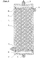
Bei der in Fig. 3 dargestellten Ausführungsform der neuerungsgemäßen Vorrichtung ist ein Hohlfadenbündel dargestellt, bei dem insgesamt neun Hohlfäden 1 zu sehen sind, von denen je drei einzeln miteinander zu einem zopfartigen Flachgeflecht verflochten sind. Insgesamt sind also drei solcher zopfartigen Hohlfadenflachgeflechte zu erkennen, deren offene Enden von je einem gemeinsamen Rohrboden 2 gehalten werden, mit dem die Enden der Hohlfäden 1 fluiddicht verbunden sind. Die Hohlfäden 1 und die Rohrböden 2 sind in einem Gehäuse 3 mit Anschlüssen 4; 5; 6; 7 für das Zu- und Abführen von zwei Fluiden angeordnet. Die Rohrböden 2 sind mit Hilfe von Dichtringen 8 mit dem Gehäuse 3 fluiddicht verbunden. Das durch den Anschluß 4 eintretende Fluid strömt durch die Hohlfäden 1 und verläßt die Vorrichtung durch den Anschluß 5. Das andere Fluid tritt durch den Anschluß 6 in die Vorrichtung ein, umströmt die Hohlfäden 1 und verläßt die Vorrichtung durch den Anschluß 7. Bei dieser Fahrweise strömen die beiden Fluide z.T. im Kreuz-und z.T. im Gegenstrom zueinander.In the embodiment of the device according to the invention shown in FIG. 3, a hollow fiber bundle is shown, in which a total of nine
Bei der in Fig. 4 dargestellten Ausführungsform der neuerungsgemäßen Vorrichtung sind vier Hohlfäden 1 zu einem kordelförmigen Rundgeflecht einzeln miteinander verflochten. Die offenen, nach außen mündenden Enden der Hohlfäden 1 sind mit den beiden Rohrböden 2 fluiddicht verbunden. Durch die gestrichelten Linien soll verdeutlicht werden, daß die Rohrböden 2 der neuerungsgemäßen Vorrichtung auf einfache Weise auch in einem Schlauch 9 oder einem Rohr 9 fluiddicht angeordnet werden können, so daß - wie durch die Pfeile angezeigt - ein Fluid durch die Hohlfäden 1 hindurchgeleitet werden kann, während mit einem anderen Fluid - wie ebenfalls durch Pfeile angedeutet - die Hohlfäden l von außen quer angeströmt, also umströmt werden können. Hierbei strömen beide Fluide also im Kreuzstrom zueinander.In the embodiment of the device according to the invention shown in FIG. 4, four
In Fig. 5 ist eine Ausführungsform der neuerungsgemäßen Vorrichtung dargestellt, bei der die Hohlfäden 1 und die Rohrböden 2 wiederum in einem Gehäuse 3 mit Anschlüssen 4; 5; 6; 7 für das Zu- und Abführen von zwei fluiden Stoffen angeordnet sind, mit welchem die Rohrböden 2 fluiddicht verbunden sind. Die Anschlüsse 4; 5; 6; 7 sind hierbei so angeordnet, daß die beiden an der Wärme- bzw. Stoffübertragung beteiligten Fluide z.T. im Kreuz- und z.T. im Gleichstrom zueinander strömen. Bei dieser Ausführungsform sind jeweils neun Hohlfäden 1 einzeln zu einem Flachgeflecht miteinander verflochten. Mehrere solche Flachgeflechte können dabei - auch leicht versetzt zueinander - übereinandergestapelt und deren offene Enden von insgesamt zwei gemeinsamen Rohrböden 2, mit denen sie fluiddicht verbunden sind, gehalten sein.FIG. 5 shows an embodiment of the device according to the innovation, in which the
In Fig. 6 ist ein Zopf geflecht dargestellt, bei dem insgesamt drei Hohlfäden 1 einzeln miteinander verflochten sind. Im Vergleich zu der in Fig. 2 dargestellten Ausführungsform kreuzen sich hierbei die Hohlfäden 1 unter einem spitzen Winkel. Diese Art der Verflechtung ist für Hohlfäden mit einer etwas höheren Biegesteifigkeit, also mit einer geringeren Flexibilität, geeignet.In Fig. 6 a braid is shown, in which a total of three
Verglichen wurde die Stoffübertragungsleistung einer neuerungsgemäßen Vorrichtung mit einer Vorrichtung, bei der die Hohlfäden parallel und in Abständen zueinander angeordnet waren. Beide Vorrichtungen hatten insgesamt 216 poröse Hohlfäden aus Polypropylen mit einem Porenvolumen von 76%, einem maximalen Porendurchmesser von 0,53 µm, einem Außendurchmesser von 2,6 mm und einem Innendurchmesser von 1,8 mm. In der neuerungsgemäßen Vorrichtung waren jeweils drei Hohlfäden zu einem zopfartigen Vollgeflecht einzeln miteinander verflochten, d.h. das Hohlfadenbündel wurde bei dieser Ausführungsform also von 72 solchen zopfartigen Hohlfadenvollgeflechten gebildet. Die wirksame Länge der Hohlfäden betrug bei der neuerungsgemäßen Vorrichtung 530 mm, bei der herkömmlichen 620 mm, die Austauschfläche,bezogen auf den Hohlfadeninnendurchmesser, betrug bei der neuerungsgemäßen Vorrichtung ca. 0,65 m2, bei der herkömmlichen ca. 0,76 m2. Jedes Hohlfadenbündel war in einem rohrförmigen Gehäuse angeordnet, das einen Innendurchmesser von 60 mm hatte. Der Füllgrad betrug somit in beiden Fällen ca. 40,6%.The mass transfer performance of a device according to the invention was compared with a device in which the hollow threads were arranged parallel and at intervals from one another. Both devices had a total of 216 porous hollow threads made of polypropylene with a pore volume of 76%, a maximum pore diameter of 0.53 μm, an outer diameter of 2.6 mm and an inner diameter of 1.8 mm. In the device according to the innovation, three hollow threads were individually interwoven to form a braid-like full braid, ie in this embodiment the hollow-fiber bundle was formed from 72 such braid-like hollow braids. The effective length of the hollow threads was 530 mm in the device according to the innovation, in the conventional 620 mm, the exchange area, based on the inside diameter of the hollow thread, was approx. 0.65 m 2 in the device according to the innovation and approx. 0.76 m 2 in the conventional device . Each bundle of hollow fibers was arranged in a tubular housing which had an inner diameter of 60 mm. The degree of filling was thus approximately 40.6% in both cases.
Zum Vergleich wurden die bei der Transmembrandestillation unter verschiedenen Versuchsbedingungen von der Destillandseite durch die Poren der Hohlfäden zur Destillatseite veriampften Wassermengen herangezogen. Als Ausgangsflüssigkeit (Destilland)wurde eine 0,1%-ige NaCl-Lösung verwendet, die durch die Hohlfäden geleitet wurde, wobei Durchsätze im Bereich von 100 bis 750 1/h und Temperaturen im Bereich von 30 bis 90°C eingestellt wurden. Für den Destillatkreislauf wurde reines Wasser verwendet, wobei jeweils die gleichen Durchsätze wie im Warmkreislauf (Destillandkreislauf) und Temperaturen im Bereich von 15 bis 26°C eingestellt wurden. Die Temperatur des Destillands wurde um 4°C bis 75°C höher eingestellt als die des Destillatkreislaufes.For comparison, the amounts of water evaporated during transmembrane distillation under different test conditions from the distillate side through the pores of the hollow fibers to the distillate side were used. A 0.1% NaCl solution was used as the starting liquid (distilland), which was passed through the hollow filaments, with throughputs in the range from 100 to 750 l / h and temperatures in the range from 30 to 90 ° C. being set. Pure water was used for the distillate cycle, the same in each case Throughputs as in the warm cycle (distillery cycle) and temperatures in the range of 15 to 26 ° C were set. The temperature of the distillate was set 4 ° C to 75 ° C higher than that of the distillate cycle.
Während die mit der herkömmlichen Vorrichtung gewonnenen Destillatmengen nur im Bereich von 1 bis 10 1/m2h lagen, wurden mit der neuerungsgemäßen Vorrichtung Destillatmengen im im Bereich von 2 bis 15 1/m2h erreicht. Das bedeutet, daß mit der erfindungsgemäßen Vorrichtung eine um 50% bis 100% höhere Stoffübertragungsleistung unter sonst gleichen Bedingungen erreicht wurde, wobei die relativ höheren Leistungswerte bei niedrigeren Durchsätzen und niedrigeren Temperaturen im Warmkreislauf bzw. niedrigeren Temperaturdifferenzen zwischen Destillandseite und Destillatseite erreicht wurden.While the amounts of distillate obtained with the conventional device were only in the range from 1 to 10 1 / m 2 h, amounts of distillate in the range from 2 to 15 1 / m 2 h were achieved with the device according to the innovation. This means that a 50% to 100% higher mass transfer performance was achieved under otherwise identical conditions with the device according to the invention, the relatively higher performance values being achieved at lower throughputs and lower temperatures in the hot circuit or lower temperature differences between the distillate side and the distillate side.
Claims (7)
Applications Claiming Priority (2)
| Application Number | Priority Date | Filing Date | Title |
|---|---|---|---|
| DE19853508382 DE3508382A1 (en) | 1985-03-08 | 1985-03-08 | DEVICE FOR THE TRANSFER OF HEAT AND / OR FABRIC WITH THE AID OF CAVE THREADS |
| DE3508382 | 1985-03-08 |
Publications (2)
| Publication Number | Publication Date |
|---|---|
| EP0193946A2 true EP0193946A2 (en) | 1986-09-10 |
| EP0193946A3 EP0193946A3 (en) | 1987-10-14 |
Family
ID=6264673
Family Applications (1)
| Application Number | Title | Priority Date | Filing Date |
|---|---|---|---|
| EP86102908A Withdrawn EP0193946A3 (en) | 1985-03-08 | 1986-03-05 | Apparatus for heat transfer using hollow filaments |
Country Status (4)
| Country | Link |
|---|---|
| EP (1) | EP0193946A3 (en) |
| JP (1) | JPS61262591A (en) |
| DE (2) | DE8506819U1 (en) |
| DK (1) | DK104786A (en) |
Cited By (10)
| Publication number | Priority date | Publication date | Assignee | Title |
|---|---|---|---|---|
| CH676677A5 (en) * | 1989-01-27 | 1991-02-28 | Sulzer Ag | Permeable tubular membrane holding moving medium - transfers material to or from transversely flowing fluid medium |
| DE19652695C1 (en) * | 1996-12-18 | 1997-10-30 | Saxonia Medical Gmbh | Hollow fibre module e.g. for blood dialysis, filtration, oxygenation, etc. |
| WO2003029775A2 (en) | 2001-10-01 | 2003-04-10 | Mykrolis Corporation | Thermoplastic apparatus for conditioning the temperature of a fluid |
| EP1432955A2 (en) * | 2001-10-01 | 2004-06-30 | Mykrolis Corporation | A thermoplastic heat exchanger and method of making the same |
| WO2010006816A1 (en) * | 2008-07-18 | 2010-01-21 | Donald Herbst | Heat exchanger, method for operating the heat exchanger and use of the heat exchanger in an air conditioner |
| WO2010128044A1 (en) * | 2009-05-04 | 2010-11-11 | Fresenius Medical Care Deutschland Gmbh | Apparatus and method for producing a hollow fiber bundle having undulated phase-shifted hollow fibers |
| DE102009038673A1 (en) * | 2009-08-24 | 2011-03-03 | Dritte Patentportfolio Beteiligungsgesellschaft Mbh & Co.Kg | Lathing of the hollow fiber during fabric (energy) transport operations in exchanger (hollow fiber) modules |
| WO2013113362A1 (en) * | 2012-01-30 | 2013-08-08 | A-Heat Allied Heat Exchange Technology Ag | Heat exchanger |
| EP2208956A3 (en) * | 2009-01-16 | 2013-10-16 | Mahle International GmbH | Method for manufacturing a heat exchanger |
| CN114127550A (en) * | 2019-08-05 | 2022-03-01 | 株式会社日立高新技术 | Degassing device and electrolyte measurement system |
Families Citing this family (4)
| Publication number | Priority date | Publication date | Assignee | Title |
|---|---|---|---|---|
| DE29510720U1 (en) * | 1995-07-01 | 1995-09-07 | Balcke Duerr Ag | Heat exchanger |
| JP2012193911A (en) * | 2011-03-17 | 2012-10-11 | Toray Ind Inc | Heat exchanger |
| DE102014202536A1 (en) * | 2014-02-12 | 2015-08-13 | MAHLE Behr GmbH & Co. KG | Pipe arrangement for a charge air cooler |
| CN106767038A (en) * | 2016-11-28 | 2017-05-31 | 珠海格力电器股份有限公司 | Heat exchanger and air-conditioner |
Citations (9)
| Publication number | Priority date | Publication date | Assignee | Title |
|---|---|---|---|---|
| DE1932027A1 (en) * | 1968-06-24 | 1970-01-15 | Clarke Chapman Ltd | Heat exchanger |
| US3557962A (en) * | 1968-06-28 | 1971-01-26 | North American Rockwell | Reverse osmosis fabric |
| DE1642811A1 (en) * | 1964-12-09 | 1971-05-06 | Dow Chemical Co | Diffusion cell, diffusion device and method of manufacture |
| DE2426591A1 (en) * | 1973-06-01 | 1974-12-12 | Rhone Poulenc Sa | DEVICE WITH HOLLOW FIBERS |
| US3854523A (en) * | 1971-08-19 | 1974-12-17 | Du Pont | Liquid heat exchange system |
| US4098852A (en) * | 1972-07-04 | 1978-07-04 | Rhone-Poulenc, S.A. | Process for carring out a gas/liquid heat-exchange |
| FR2381000A1 (en) * | 1977-02-22 | 1978-09-15 | Du Pont | DEVICE FOR SEPARATION CONSISTING OF HOLLOW FILAMENTS OF RIGID POROUS INORGANIC MATERIAL AND ITS USE |
| DE2818946A1 (en) * | 1976-02-13 | 1979-11-08 | Baxter Travenol Lab | Hollow filament dialyser and hank winder for filaments - allowing number of filament bundles to be wound simultaneously |
| US4583969A (en) * | 1984-06-26 | 1986-04-22 | Mortensen J D | Apparatus and method for in vivo extrapulmonary blood gas exchange |
Family Cites Families (11)
| Publication number | Priority date | Publication date | Assignee | Title |
|---|---|---|---|---|
| DE1991551U (en) * | 1968-08-14 | E I du Pont de Nemours and Company, Wilmington, Del (V St A) | Heat exchanger | |
| DE845947C (en) * | 1948-02-07 | 1952-08-07 | Const Mecano Thermiques C O M | Heaters for liquids and gases, especially boilers or crackers, with pressure firing |
| US3419069A (en) * | 1967-04-28 | 1968-12-31 | Du Pont | Heat transfer apparatus having flexible plastic tubular elements arranged in a braided configuration |
| FR2222134A1 (en) * | 1973-03-19 | 1974-10-18 | Rhone Poulenc Sa | Appts for permeation through hollow fibres - allows simple construction and efficient separation and mixing processes |
| US4446024A (en) * | 1977-02-22 | 1984-05-01 | E. I. Du Pont De Nemours & Company | Hollow filament product |
| US4140637A (en) * | 1977-10-06 | 1979-02-20 | Walter Carl W | Permeability separatory method and apparatus |
| DE3026954C2 (en) * | 1979-07-16 | 1985-05-09 | Institut metallurgii imeni A.A. Bajkova Akademii Nauk SSSR, Moskau/Moskva | Heat exchange device |
| DE8007199U1 (en) * | 1980-03-15 | 1981-06-11 | Genkinger, Helmut, 7293 Pfalzgrafenweiler | TUBE ABSORBER BUILDING UNIT, IN PARTICULAR FOR SOLAR USE SYSTEMS |
| DE3124048C2 (en) * | 1981-06-15 | 1984-05-30 | Donald Dipl.-Ing. 1000 Berlin Herbst | Pipeline mesh for hot water surface heating of floors or walls |
| EP0112366A1 (en) * | 1982-06-29 | 1984-07-04 | AB Zander & Ingestrom | Tube heat exchanger |
| DE3309923C2 (en) * | 1983-03-19 | 1985-10-31 | Rolf Dipl.-Ing. 4100 Duisburg Bähr | Heat exchanger |
-
1985
- 1985-03-08 DE DE8506819U patent/DE8506819U1/en not_active Expired
- 1985-03-08 DE DE19853508382 patent/DE3508382A1/en not_active Withdrawn
-
1986
- 1986-03-05 EP EP86102908A patent/EP0193946A3/en not_active Withdrawn
- 1986-03-07 JP JP61050271A patent/JPS61262591A/en active Pending
- 1986-03-07 DK DK104786A patent/DK104786A/en not_active Application Discontinuation
Patent Citations (9)
| Publication number | Priority date | Publication date | Assignee | Title |
|---|---|---|---|---|
| DE1642811A1 (en) * | 1964-12-09 | 1971-05-06 | Dow Chemical Co | Diffusion cell, diffusion device and method of manufacture |
| DE1932027A1 (en) * | 1968-06-24 | 1970-01-15 | Clarke Chapman Ltd | Heat exchanger |
| US3557962A (en) * | 1968-06-28 | 1971-01-26 | North American Rockwell | Reverse osmosis fabric |
| US3854523A (en) * | 1971-08-19 | 1974-12-17 | Du Pont | Liquid heat exchange system |
| US4098852A (en) * | 1972-07-04 | 1978-07-04 | Rhone-Poulenc, S.A. | Process for carring out a gas/liquid heat-exchange |
| DE2426591A1 (en) * | 1973-06-01 | 1974-12-12 | Rhone Poulenc Sa | DEVICE WITH HOLLOW FIBERS |
| DE2818946A1 (en) * | 1976-02-13 | 1979-11-08 | Baxter Travenol Lab | Hollow filament dialyser and hank winder for filaments - allowing number of filament bundles to be wound simultaneously |
| FR2381000A1 (en) * | 1977-02-22 | 1978-09-15 | Du Pont | DEVICE FOR SEPARATION CONSISTING OF HOLLOW FILAMENTS OF RIGID POROUS INORGANIC MATERIAL AND ITS USE |
| US4583969A (en) * | 1984-06-26 | 1986-04-22 | Mortensen J D | Apparatus and method for in vivo extrapulmonary blood gas exchange |
Non-Patent Citations (1)
| Title |
|---|
| PRODUCT LICENSING INDEX, RESEARCH DISCLOSURES, Nr. 89, September 1971, Seite 51, Havant, GB; "Selective permeation separation devices" * |
Cited By (20)
| Publication number | Priority date | Publication date | Assignee | Title |
|---|---|---|---|---|
| CH676677A5 (en) * | 1989-01-27 | 1991-02-28 | Sulzer Ag | Permeable tubular membrane holding moving medium - transfers material to or from transversely flowing fluid medium |
| DE19652695C1 (en) * | 1996-12-18 | 1997-10-30 | Saxonia Medical Gmbh | Hollow fibre module e.g. for blood dialysis, filtration, oxygenation, etc. |
| US8091618B2 (en) | 2001-10-01 | 2012-01-10 | Entegris, Inc. | Exchange apparatus |
| WO2003029775A2 (en) | 2001-10-01 | 2003-04-10 | Mykrolis Corporation | Thermoplastic apparatus for conditioning the temperature of a fluid |
| EP1432955A2 (en) * | 2001-10-01 | 2004-06-30 | Mykrolis Corporation | A thermoplastic heat exchanger and method of making the same |
| EP1432955A4 (en) * | 2001-10-01 | 2006-05-17 | Entegris Inc | A thermoplastic heat exchanger and method of making the same |
| US7308932B2 (en) | 2001-10-01 | 2007-12-18 | Entegris, Inc. | Exchange apparatus |
| CN100380083C (en) * | 2001-10-01 | 2008-04-09 | 安格斯公司 | Exchange apparatus |
| EP1433036A4 (en) * | 2001-10-01 | 2008-10-22 | Entegris Inc | Apparatus for conditioning the temperature of a fluid |
| SG157235A1 (en) * | 2001-10-01 | 2009-12-29 | Entegris Inc | A thermoplastic heat exchanger and method of making the same |
| EP1433036A2 (en) * | 2001-10-01 | 2004-06-30 | Mykrolis Corporation | Apparatus for conditioning the temperature of a fluid |
| EP2275766A1 (en) * | 2001-10-01 | 2011-01-19 | Entegris, Inc. | Tubular heat or mass exchange apparatus |
| WO2010006816A1 (en) * | 2008-07-18 | 2010-01-21 | Donald Herbst | Heat exchanger, method for operating the heat exchanger and use of the heat exchanger in an air conditioner |
| EP2208956A3 (en) * | 2009-01-16 | 2013-10-16 | Mahle International GmbH | Method for manufacturing a heat exchanger |
| WO2010128044A1 (en) * | 2009-05-04 | 2010-11-11 | Fresenius Medical Care Deutschland Gmbh | Apparatus and method for producing a hollow fiber bundle having undulated phase-shifted hollow fibers |
| DE102009038673A1 (en) * | 2009-08-24 | 2011-03-03 | Dritte Patentportfolio Beteiligungsgesellschaft Mbh & Co.Kg | Lathing of the hollow fiber during fabric (energy) transport operations in exchanger (hollow fiber) modules |
| DE102009038673A8 (en) * | 2009-08-24 | 2011-06-01 | Dritte Patentportfolio Beteiligungsgesellschaft Mbh & Co.Kg | Lathing of the hollow fiber during fabric (energy) transport operations in exchanger (hollow fiber) modules |
| WO2013113362A1 (en) * | 2012-01-30 | 2013-08-08 | A-Heat Allied Heat Exchange Technology Ag | Heat exchanger |
| CN114127550A (en) * | 2019-08-05 | 2022-03-01 | 株式会社日立高新技术 | Degassing device and electrolyte measurement system |
| EP4012394A4 (en) * | 2019-08-05 | 2023-08-09 | Hitachi High-Tech Corporation | Deaerator and electrolyte measurement system |
Also Published As
| Publication number | Publication date |
|---|---|
| EP0193946A3 (en) | 1987-10-14 |
| DK104786D0 (en) | 1986-03-07 |
| DK104786A (en) | 1986-09-09 |
| DE3508382A1 (en) | 1986-09-11 |
| JPS61262591A (en) | 1986-11-20 |
| DE8506819U1 (en) | 1986-07-03 |
Similar Documents
| Publication | Publication Date | Title |
|---|---|---|
| EP0371189B1 (en) | Hollow fibre module, process for its manufacture and apparatus for carrying out said process | |
| EP0732141B1 (en) | Hollow filament bundle and mass and/or heat exchanger | |
| EP0285812B1 (en) | Multiple layer hollow fibre assembly | |
| EP0265823B1 (en) | Process for making a hollow fibre mass exchange module, and module thus produced | |
| EP0193946A2 (en) | Apparatus for heat transfer using hollow filaments | |
| DE2338070B2 (en) | Fractionation device | |
| DE2618390B2 (en) | Device for contacting a liquid and an immiscible flowable substance | |
| DE1959394A1 (en) | Device and method for the osmotic decomposition of fluid mixtures or solutions | |
| DE2231868A1 (en) | CELL FOR CONDUCTING REVERSE OSMOSIS WITH A SWIRLING DEVICE | |
| DE2441333B2 (en) | Apparatus for separating components contained in a fluid mixture or solution and a method for producing an arrangement from hollow fibers for use in such a device | |
| DD141171A5 (en) | METHOD AND DEVICE FOR OBTAINING BICOMPONENT FAEDES | |
| EP0264696A2 (en) | Mass exchange apparatus | |
| DE2322571A1 (en) | NEW SEMIPERMEABLE TUBULAR ELEMENTS | |
| EP0521495A2 (en) | Process and apparatus for manufacturing hollow fibre modules | |
| DE4308850A1 (en) | Hollow-thread mat | |
| DE2514763A1 (en) | DIALYSIS UNIT | |
| DE1442421A1 (en) | Device for separating solutions | |
| DE2529977C3 (en) | Device with membranes on tubular supports for treating fluids | |
| DE2842835C2 (en) | Dialysis membrane hollow thread chain | |
| EP0350853B1 (en) | Process and device for filtering gaseous or liquid dispersions | |
| EP2708279B1 (en) | Three-dimensional hollow fiber module for mass and energy transfer operations | |
| DE2721008A1 (en) | METHOD AND DEVICE FOR MANUFACTURING DEVICES WITH HOLLOW FIBER | |
| DE19532365C2 (en) | Hollow fiber oxygenator | |
| WO2019092105A1 (en) | Membrane bundle package having spacers | |
| DE4129400A1 (en) | METHOD FOR PRODUCING A HOLLOW FILM BODY |
Legal Events
| Date | Code | Title | Description |
|---|---|---|---|
| PUAI | Public reference made under article 153(3) epc to a published international application that has entered the european phase |
Free format text: ORIGINAL CODE: 0009012 |
|
| AK | Designated contracting states |
Kind code of ref document: A2 Designated state(s): BE DE FR GB IT NL SE |
|
| PUAL | Search report despatched |
Free format text: ORIGINAL CODE: 0009013 |
|
| AK | Designated contracting states |
Kind code of ref document: A3 Designated state(s): BE DE FR GB IT NL SE |
|
| 17P | Request for examination filed |
Effective date: 19871105 |
|
| RAP1 | Party data changed (applicant data changed or rights of an application transferred) |
Owner name: AKZO PATENTE GMBH |
|
| 17Q | First examination report despatched |
Effective date: 19890202 |
|
| STAA | Information on the status of an ep patent application or granted ep patent |
Free format text: STATUS: THE APPLICATION HAS BEEN WITHDRAWN |
|
| 18W | Application withdrawn |
Withdrawal date: 19901005 |
|
| R18W | Application withdrawn (corrected) |
Effective date: 19901005 |
|
| RIN1 | Information on inventor provided before grant (corrected) |
Inventor name: TRUMMER, ALFRED, DIPL.-ING. Inventor name: GEMEINHARDT, HERMANN |