EP0246519A2 - Apparatus for transferring weight - Google Patents
Apparatus for transferring weight Download PDFInfo
- Publication number
- EP0246519A2 EP0246519A2 EP87106731A EP87106731A EP0246519A2 EP 0246519 A2 EP0246519 A2 EP 0246519A2 EP 87106731 A EP87106731 A EP 87106731A EP 87106731 A EP87106731 A EP 87106731A EP 0246519 A2 EP0246519 A2 EP 0246519A2
- Authority
- EP
- European Patent Office
- Prior art keywords
- mower
- pedal
- spring
- linkage
- arrangement
- Prior art date
- Legal status (The legal status is an assumption and is not a legal conclusion. Google has not performed a legal analysis and makes no representation as to the accuracy of the status listed.)
- Withdrawn
Links
- 230000000284 resting effect Effects 0.000 claims 1
- 230000005540 biological transmission Effects 0.000 description 1
- 238000006243 chemical reaction Methods 0.000 description 1
- 238000010411 cooking Methods 0.000 description 1
- 230000005484 gravity Effects 0.000 description 1
Images


Classifications
-
- A—HUMAN NECESSITIES
- A01—AGRICULTURE; FORESTRY; ANIMAL HUSBANDRY; HUNTING; TRAPPING; FISHING
- A01D—HARVESTING; MOWING
- A01D34/00—Mowers; Mowing apparatus of harvesters
- A01D34/01—Mowers; Mowing apparatus of harvesters characterised by features relating to the type of cutting apparatus
- A01D34/412—Mowers; Mowing apparatus of harvesters characterised by features relating to the type of cutting apparatus having rotating cutters
- A01D34/63—Mowers; Mowing apparatus of harvesters characterised by features relating to the type of cutting apparatus having rotating cutters having cutters rotating about a vertical axis
- A01D34/64—Mowers; Mowing apparatus of harvesters characterised by features relating to the type of cutting apparatus having rotating cutters having cutters rotating about a vertical axis mounted on a vehicle, e.g. a tractor, or drawn by an animal or a vehicle
-
- A—HUMAN NECESSITIES
- A01—AGRICULTURE; FORESTRY; ANIMAL HUSBANDRY; HUNTING; TRAPPING; FISHING
- A01D—HARVESTING; MOWING
- A01D2101/00—Lawn-mowers
Definitions
- the invention relates to a device for transmitting the weight of a working device, in particular a mower, attached to the front of a motor vehicle, in particular a garden tractor, with a manually operable adjusting device for adjusting a linkage arrangement for the working device or mower between an ineffective and an effective working position.
Abstract
Eine Gewichtsverteilungsvorrichtung (40) für ein an der Frontseite eines Gartenschleppers (10) angeordnetes Mähwerk (28) ist mit einem Pedal (42) ausgerüstet, das bei Betätigung über eine Gestängeanordnung auf die Gewichtsverteilungsvorrichtung einwirkt und wahlweise einen Teil des Gewichtes des Mähwerkes (28) auf den Gartenschlepper (10) überträgt. Das Pedal (42) weist eine Torsionsfeder (70) auf, die einenends einen Teil des Gewichtes des Mähwerkes (28) auffängt, anderenends gegen eine federbeaufschlagte Tragplatte anliegt und sich damit am Gartenschlepper abstützt.A weight distribution device (40) for a mower (28) arranged on the front of a garden tractor (10) is equipped with a pedal (42) which, when actuated via a linkage arrangement, acts on the weight distribution device and optionally a part of the weight of the mower (28) transfers to the garden tractor (10). The pedal (42) has a torsion spring (70) which at one end absorbs part of the weight of the mower deck (28) and at the other end rests against a spring-loaded support plate and is thus supported on the garden tractor.
Description
Die Erfindung bezieht sich auf eine Vorrichtung zur Übertragung des Gewichtes eines am Kraftfahrzeug, insbesondere Gartenschlepper, frontseitig angebrachten Arbeitsgerätes, insbesondere Mähwerkes, mit einer manuell betätigbaren Stellvorrichtung zur Verstellung einer Gestängeanordnung für das Arbeitsgerät bzw. Mähwerk zwischen einer unwirksamen und einer wirksamen Arbeitsstellung.The invention relates to a device for transmitting the weight of a working device, in particular a mower, attached to the front of a motor vehicle, in particular a garden tractor, with a manually operable adjusting device for adjusting a linkage arrangement for the working device or mower between an ineffective and an effective working position.
Es ist bereits allgemein ein Gartenschlepper mit einem an der Frontseite angebrachten Mähwerk bekannt, das über eine Gestängeanordnung an die Unterseite des Gartenschleppers angeschlossen ist und über einen handbetätigbaren Hebel zwischen einer abgesenkten und einer angehobenen Stellung verstellbar ist. Arbeiten derartige Gartenschlepper mit frontseitig montiertem Mähwerk an einem Hang, so verschiebt sich der Schwerpunkt des Fahrzeuges entweder nach vorne oder nach hinten. Dadurch wird auch eine Gewichtsverlagerung des Schleppers auf den Rädern herbeigeführt, so daß ein Durchrutschen der angetriebenen Räder auftreten kann, wenn diese nicht mehr ausreichend belastet werden.It is already generally known a garden tractor with a mower attached to the front, which is connected via a linkage arrangement to the underside of the garden tractor and is adjustable between a lowered and a raised position by means of a manually operable lever. If garden tractors of this type work with a mower mounted on the front on a slope, the center of gravity of the vehicle either shifts forward or backward. This also brings about a shift in the weight of the tractor on the wheels, so that the driven wheels can slip when they are no longer sufficiently loaded.
Demgegenüber liegt der Erfindung die Aufgabe zugrunde, das Arbeitsgerät, insbesondere das Mähwerk, an dem Kraftfahrzeug bzw. dem Gartenschlepper derart anzuordnen, daß mit relativ einfachem baulichen Aufwand das Gewicht des Arbeitsgerätes derart gelagert werden kann, daß stets eine ausreichende Bodenhaftung des Fahrzeuges gewährleistet ist. Diese Aufgabe ist durch die im kennzeichnenden Teil des Anspruches 1 aufgeführten Merkmale gelöst. Durch die vorteilhafte Verwendung der Gewichtsverteilungsvorrichtung wird in relativ kurzer Zeit eine Verlagerung des Arbeitsgerätes bzw. des Mähwerkes am Fahrzeug herbeigeführt, indem hierzu das Pedal betätigt wird, das dann eine entsprechende Verstellung des Arbeitsgerätes herbeiführt. Durch diese Anordnung besteht für die Bedienungsperson die Möglichkeit, auch bei Arbeiten am Hang eine relativ schnelle Gewichtsverlagerung des Arbeitsgerätes herbeizuführen, so daß eine ausreichende Belastung des zuvor weniger belasteten Laufrades herbeigeführt wird. Das Pedal ist hierzu in vorteilhafter Weise über einen Hebelarm und eine Gestängeanordnung mit einer Feder verbunden, die einenends am Kraftfahrzeug angeschlossen ist. Ferner ist der Gestängeanordnung eine Spielverbindung bzw. eine Schlitzführung zugeordnet, die eine vertikale Verstellung des Arbeitsgerätes bzw. des Mähwerkes gestattet, ohne dabei einen Einfluß auf die Bewegung des Pedales zu nehmen. Der Gestängeanordnung ist auch ferner eine vorspannbare Feder zugeordnet, die ca. 20 % des Gewichtes des Mähwerkes auf das Fahrzeug überträgt, wenn die Feder hierzu gespannt wird. Beispielsweise ist es im Arbeitseinsatz erforderlich, daß ein Teil des Gewichtes des Mähwerkes zusätzlich auf das Fahrzeug übertragen wird, dann braucht die Bedienungsperson lediglich das Pedal zu betätigen, um somit eine Torsionsfeder zu verdrehen, die dann 80 % des Gewichtes des Arbeitsgeräts bzw. des Mähwerkes aufnimmt. Soll beispielsweise das Arbeitsgerät bzw. das Mähwerk und somit die zugehörige Gewichtsverteilungsvorrichtung von ihrer aktiven Stellung in ihre inaktive Stellung verstellt werden, so braucht die Bedienungsperson lediglich das Pedal weniger zu belasten, da dieses dann aufgrund der Torsionsfeder und der Feder bzw. der Totpunkt-Federanordnung in seine inaktive, d. h. unbelastete Stellung verstellt wird. Die Spielverbindung bzw. die Schlitzführung gestattet in dieser Stellung eine Verstellung des Arbeitsgerätes ohne Beeinflussung des Pedales. Durch die vorteilhafte Anordnung der einzelnen Gestänge sowie der Gewichtsverteilungsvorrichtung läßt sich somit in kürzester Zeit bis zu 80 % des Gewichtes des Mähwerkes auf das Fahrzeug übertragen, ohne daß die Bedienungsperson große Umrüstarbeiten an dem Arbeitsgerät bzw. an dem Mähwerk vorzunehmen braucht. Im folgenden wird die Erfindung anhand von lediglich einen Ausführungsweg darstellenden Zeichnungen erläutert. Es zeigen:
- Fig. 1 eine Seitenansicht eines Gartenschleppers mit einem an der Stirnseite angeschlossenen Mähwerk,
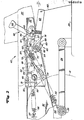
- Fig. 2 eine Seitenansicht der Gestängeanordnung für das Mähwerk in der angehobenen Stellung,
- Fig. 3 eine ähnliche Ansicht wie in Fig. 2, jedoch mit abgesenktem Mähwerk,
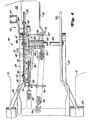
- Fig. 4 eine Draufsicht der Gestängeanordnung zur Aufnahme des Mähwerkes.
- 1 is a side view of a garden tractor with a mower connected to the front,
- 2 is a side view of the linkage arrangement for the mower in the raised position,
- 3 is a view similar to FIG. 2, but with the mower lowered,
- Fig. 4 is a plan view of the linkage arrangement for receiving the mower.
In der Zeichnung ist mit 10 ein Kraftfahrzeug bzw. ein Gartenschlepper bezeichnet, der sich auf zwei vorderen, antreibbaren Laufrädern 12 und einem hinteren steuerbaren Laufrad 14 abstützt. Der Gartenschlepper 10 ist ferner mit einem Lenkrad 16 und dahinter mit einem Fahrersitz 18 ausgerüstet, neben dem die einzelnen Bedienungselemente 20 angeordnet sind. Weitere Bedienungselemente, beispielsweise Pedale zur Betätigung des Gartenschleppers, sind in der Zeichnung der Einfachheit halber nicht dargestellt. An die vordere Antriebsachse 26 sind Tragarme 24 angeschlossen, die zur Aufnahme eines Mähwerkes 28 dienen. An der Stirnseite des Mähwerkes 28 ist ein Stützrad 30 angeordnet, das in seiner Höhe einstellbar ist, um somit die Schnitthöhe des Mähwerkes 28 verändern zu können.In the drawing, 10 denotes a motor vehicle or a garden tractor, which is supported on two front
Eine Gewichtsübertragungs- bzw. Gewichtsverteilungsvorrichtung 40 der vorliegenden Erfindung besteht aus einer an der Unterseite der Plattform 22 des Gartenschleppers 10 vorgesehenen Gestängeanordnung. Wie aus den Figuren 2 und 4 hervorgeht, ist die Gewichtsübertragungsvorrichtung 40 im wesentlichen vor der Antriebsachse 26 und insbesondere zwischen Rahmenträgern 32 zur Aufnahme der Plattform 22 angeordnet. Ein Pedal 42 ist links vom Rahmenträger 32 angeordnet und schwenkt um eine im Rahmenträger 32 vorgesehene Achse 43. Das Pedal 42 besteht aus einer Pedalplatte 44, die sich oberhalb der Plattform 22 erstreckt. Die Pedalplatte 44 kann mit einer nicht rutschenden Auflage versehen sein. Das Pedal 42 ist über die Achse 43 mit einem Hebel 46 verbunden, der sich an der Innenseite des linken Rahmenträgers 32 erstreckt. Das obere Ende des Hebels weist eine Bohrung 47 zum Anschluß eines Gestänges 67 auf. Das Gestänge 67 ist S-förmig ausgebildet und besteht aus einem quer zur Bewegungsrichtung des Gartenschleppers verlaufenden Gestängeteil sowie einem sich in Fahrtrichtung erstreckenden Gestängeteil 48. Das hinten liegende Ende des Gestängeteils 48 weist einen abgewinkelten Gestängeteil 49 auf, der in einer Bohrung einer dreieckförmigen Stellplatte aufgenommen ist.A
Die dreieckförmig ausgebildete Stellplatte 52 ist an eine am Rahmenträger 32 angeordnete Achse 53 schwenkbar angeschlossen. Die Stellplatte 52 kann in einem bestimmten Bereich gedreht bzw. geschwenkt werden, der durch eine Anschlagplatte 51 begrenzt wird, die an einem Querträger 50 angeordnet ist. Das eine Ende eines C-förmigen Lenkers 56 ist in einem kreisförmigen Schlitz 54 aufgenommen, der in dem unteren Teil der Stellplatte 52 vorgesehen ist. Das andere Ende des C-förmig ausgebildeten Lenkers 56 ist über einen abgewinkelten Gestängeteil 57 an einer L-förmig ausgebildeten Tragplatte 60 angeschlossen, die Teil der Gewichtsverteilungsvorrichtung 40 ist.The triangular-
Die L-förmige Tragplatte 60 ist auf einer länglichen, quer verlaufenden Buchse angeordnet, die auf einer zwischen den Rahmenträgern 32 befestigten Achse 64 drehbar gelagert ist. Die Tragplatte 60 weist eine sich in Längsrichtung des Gartenschleppers 10 erstreckende Platte 66 mit einer quer verlaufenden Platte 68 auf, die mit oberen und unteren Anschlußösen 67 und 69 ausgestattet ist.The L-
Die Achse 64 ist in den Rahmenträgern 32 drehbar aufgenommen und mit einem sich nach vorne erstreckenden Hubarm 63 und einem sich nach oben erstreckenden Hebelarm 65 fest verbunden. Der Hubarm 63 ist zwischen den seitlich herausstehenden Ösen.67 und 69, die eine U-förmige Aussparung bilden, aufgenommen, wobei die Unterseite des Hubarmes 63 gegen eine sich nach vorne erstreckende Torsionsfeder 74 abstützt, deren Stellkraft mit Bezug auf Fig. 2 und 3 nach oben gerichtet ist. Der Hubarm 63 ist ferner über ein flexibles Kabel 80 an das Gehäuse des Mähwerkes 28 angeschlossen. Eine vorgespannte Feder 82 ist einenends an den Hebelarm 65 und anderenends an eine Öse einer Halterung 84 angeschlossen und nimmt somit 20 % des Gewichtes des Mähwerkes 28 auf und überträgt dieses auf das Fahrzeug.The
Eine Pedalfeder 86 ist einenends an eine Öse 87 und anderenends an eine Lasche 88 angeschlossen. Die Lasche 88 ist wiederum an der Stellplatte 52 mittels eines Schraubenbolzens 55 befestigt. Die Lasche 88 weist eine Aussparung 89 auf, die zur Aufnahme des C-förmig ausgebildeten Lenkers 56 dient, wenn die Gewichtsverteilungsvorrichtung 40 gemäß Fig. 3 voll zur Wirkung kommt. Die Pedalfeder 86 dient zur Spannung bzw. Druckbeaufschlagung des Pedales 42, um es anzuheben, wenn die Wirkungslinie oberhalb der Achse 53 verläuft. Die Feder reduziert den Druck auf das Pedal 42, wenn die Linie unterhalb der Achse 53 verläuft (siehe Fig. 3).A
In der nicht belasteten Stellung gemäß Fig. 2 überträgt die Gewichtsverteilungsvorrichtung 40 20 % des Gewichtes des Mähwerkes 28 auf den Gartenschlepper 10 durch Zuhilfenahme der Feder 82. Beim Mäheinsatz des Gartenschleppers 10 ist es wünschenswert, ein zusätzliches Gewicht auf den Gartenschlepper 10 zu übertragen. Hierzu drückt die Bedienungsperson lediglich das Pedal 42, um somit die Torsionsfeder 70 zu drehen, so daß anstelle von 20 % ca. 80 % des Mähwerkgewichtes von der Torsionsfeder 70 aufgefangen wird. In der vollwirksamen Stellung gemäß Fig. 3 überträgt die Gewichtsverteilungsvorrichtung 40 in etwa 80 % des Mähwerkgewichtes über die Torsionsfeder 70 auf den Gartenschlepper 10. Ein Teil des Gewichtes wird über das Stützrad 30 abgefangen, so daß bei allen Arbeitsbedingungen ein ausreichender Bodenkontakt aufrechterhalten wird und somit eine gute Schnittwirkung.2, the
Um die Gewichtsverteilungsvorrichtung aus der vollwirksamen Stellung gemäß Fig. 3 in die teilwirksame Stellung zu verstellen, belastet die Bedienungsperson das Pedal 42 weniger, so daß es in seine Stellung gemäß Fig. 2 zurückschwenkt, wobei die Pedalfeder 86 die Zurückschwenkung des Pedals 42 unterstützt. Der bogenförmige Schlitz 54 in der Stellplatte 52 gestattet eine schwimmende Bewegung der Plattform 22, ohne daß hierzu das Pedal 42 betätigt zu werden braucht. Die Benutzung bzw. der Einsatz der Gewichtsverteilungsvorrichtung 40 gestattet der Bedienungsperson, zusätzliches Gewicht des Mähwerkes auf den Gartenschlepper zu übertragen, wenn dies aufgrund des Arbeitseinsatzes notwendig sein sollte.In order to adjust the weight distribution device from the fully effective position according to FIG. 3 into the partially effective position, the operator loads the pedal 42 less so that it swings back into its position according to FIG. 2, the
Claims (8)
Applications Claiming Priority (2)
| Application Number | Priority Date | Filing Date | Title |
|---|---|---|---|
| US862860 | 1986-05-13 | ||
| US06/862,860 US4747257A (en) | 1986-05-13 | 1986-05-13 | Weight transfer control for a front mount mower |
Publications (2)
| Publication Number | Publication Date |
|---|---|
| EP0246519A2 true EP0246519A2 (en) | 1987-11-25 |
| EP0246519A3 EP0246519A3 (en) | 1988-12-21 |
Family
ID=25339567
Family Applications (1)
| Application Number | Title | Priority Date | Filing Date |
|---|---|---|---|
| EP87106731A Withdrawn EP0246519A3 (en) | 1986-05-13 | 1987-05-08 | Apparatus for transferring weight |
Country Status (4)
| Country | Link |
|---|---|
| US (1) | US4747257A (en) |
| EP (1) | EP0246519A3 (en) |
| JP (1) | JPS62285707A (en) |
| CA (1) | CA1293859C (en) |
Families Citing this family (23)
| Publication number | Priority date | Publication date | Assignee | Title |
|---|---|---|---|---|
| US4896489A (en) * | 1989-03-22 | 1990-01-30 | Deere & Company | Implement lift and flotation system with a single transversely adjustable cylinder |
| US5042236A (en) * | 1990-02-08 | 1991-08-27 | The Toro Company | Cutting reel suspension with adjustable spring downloading |
| US5065568A (en) * | 1990-07-26 | 1991-11-19 | Deere & Company | Mower deck height adjustment mechanism |
| US5203250A (en) * | 1990-12-21 | 1993-04-20 | Deere & Company | Fluid cylinder mechanism |
| US5201240A (en) * | 1991-06-14 | 1993-04-13 | Deere & Company | Vehicle control linkage mechanism |
| JP2564519Y2 (en) * | 1991-07-24 | 1998-03-09 | 金子農機株式会社 | Work machine suspension system for riding type work vehicle |
| US5355664A (en) * | 1992-12-21 | 1994-10-18 | The Toro Company | Caster wheel suspension and shaft tensioning system for turf maintenance equipment |
| US5803474A (en) * | 1993-07-16 | 1998-09-08 | Simplicity Manufacturing, Inc. | Torsion bar rear suspension for ride-on mowers |
| US5474315A (en) * | 1993-07-16 | 1995-12-12 | Simplicity Manufacturing | Torsion bar rear suspension for ride-on mowers |
| US5381647A (en) * | 1993-10-28 | 1995-01-17 | Trail-Buster Dozer, Inc. | ATV mower articulating hitch |
| JP3359837B2 (en) * | 1997-04-03 | 2002-12-24 | 株式会社クボタ | Mower lifting and lowering device for lawn mower |
| US6068064A (en) * | 1998-05-20 | 2000-05-30 | Case Corporation | Agricultural implement with ground engaging tool and fluid circuit to control same |
| US6125775A (en) * | 1998-09-29 | 2000-10-03 | Case Corporation | System for gauge wheel load adjustment |
| SE513961C2 (en) * | 1999-03-25 | 2000-12-04 | Stiga Ab | Lifting device for implements on implement-carrying vehicles |
| US7520114B2 (en) * | 2006-01-03 | 2009-04-21 | The Toro Company | Mower with ground following cutting deck and weight transfer between deck and frame |
| US7631478B2 (en) * | 2006-05-05 | 2009-12-15 | Deere & Company | Electric implement lift system for mower cutting units |
| US20090182471A1 (en) * | 2008-01-15 | 2009-07-16 | Corey Bucher | Lawn mower with weight transfer control system |
| US20090182470A1 (en) * | 2008-01-15 | 2009-07-16 | Paul Garvey | Lawn mower with weight transfer mechanism |
| US7549243B1 (en) | 2008-01-15 | 2009-06-23 | Ariens Company | Lawn mower attachment mechanism |
| US8109069B2 (en) * | 2009-04-30 | 2012-02-07 | The Toro Company | Proportional counterbalance system for mower cutting units |
| WO2011092908A1 (en) * | 2010-01-29 | 2011-08-04 | ヤンマー株式会社 | Electric ride-on mower |
| US8756903B2 (en) * | 2012-03-21 | 2014-06-24 | Kubota Corporation | Work vehicle with stroke adjustment mechanism for suspended work implement unit |
| US8919813B2 (en) * | 2012-05-09 | 2014-12-30 | Schiller Grounds Care, Inc. | Tractor weight transfer mechanism |
Citations (4)
| Publication number | Priority date | Publication date | Assignee | Title |
|---|---|---|---|---|
| US3654749A (en) * | 1970-10-05 | 1972-04-11 | Sperry Rand Corp | Mower mounting linkage |
| US3702051A (en) * | 1970-09-08 | 1972-11-07 | John Deines | Independently operable dual drive wheel riding power mower |
| FR2374835A1 (en) * | 1976-12-27 | 1978-07-21 | Massey Ferguson Inc | TRACTOR TOOL HOLDER |
| US4325211A (en) * | 1980-09-02 | 1982-04-20 | The Toro Company | Floating deck for rider mower |
Family Cites Families (7)
| Publication number | Priority date | Publication date | Assignee | Title |
|---|---|---|---|---|
| CA844284A (en) * | 1970-06-16 | Mcdonough Power Equipment | Cutter unit suspension arrangement for power mowers | |
| US2240292A (en) * | 1939-11-29 | 1941-04-29 | Deere & Co | Tractor mower |
| US2769295A (en) * | 1955-04-08 | 1956-11-06 | John Deere Plow Company | Hitch device for tractor drawn agricultural implement |
| US3706186A (en) * | 1971-07-07 | 1972-12-19 | Sperry Rand Corp | Suspension system for a mower unit |
| US3706188A (en) * | 1972-01-03 | 1972-12-19 | Poloron Products Of Indiana In | Elevating apparatus for tractor attachments |
| US4175765A (en) * | 1978-05-15 | 1979-11-27 | Dura Corporation | Parallel hitch for a belly mounted tractor appliance |
| US4310997A (en) * | 1980-04-30 | 1982-01-19 | Paul Streicher | Two point hitch construction |
-
1986
- 1986-05-13 US US06/862,860 patent/US4747257A/en not_active Expired - Lifetime
-
1987
- 1987-04-30 CA CA000536014A patent/CA1293859C/en not_active Expired - Fee Related
- 1987-05-08 EP EP87106731A patent/EP0246519A3/en not_active Withdrawn
- 1987-05-13 JP JP62116676A patent/JPS62285707A/en active Pending
Patent Citations (5)
| Publication number | Priority date | Publication date | Assignee | Title |
|---|---|---|---|---|
| US3702051A (en) * | 1970-09-08 | 1972-11-07 | John Deines | Independently operable dual drive wheel riding power mower |
| US3654749A (en) * | 1970-10-05 | 1972-04-11 | Sperry Rand Corp | Mower mounting linkage |
| FR2374835A1 (en) * | 1976-12-27 | 1978-07-21 | Massey Ferguson Inc | TRACTOR TOOL HOLDER |
| US4325211A (en) * | 1980-09-02 | 1982-04-20 | The Toro Company | Floating deck for rider mower |
| US4325211B1 (en) * | 1980-09-02 | 1988-11-29 |
Also Published As
| Publication number | Publication date |
|---|---|
| JPS62285707A (en) | 1987-12-11 |
| CA1293859C (en) | 1992-01-07 |
| EP0246519A3 (en) | 1988-12-21 |
| US4747257A (en) | 1988-05-31 |
Similar Documents
| Publication | Publication Date | Title |
|---|---|---|
| EP0246519A2 (en) | Apparatus for transferring weight | |
| EP0160823A1 (en) | Harvester-thresher | |
| DE1455582C3 (en) | Vehicle seat adjustable in two different heights | |
| DD209711A5 (en) | BODENBEARBEITUNGSGERAET | |
| EP0081742A1 (en) | Soil-working implement movable across a field | |
| DE102006034562A1 (en) | Mounted mowers | |
| EP0394830B1 (en) | Tractormounted agricultural tool, particularly circular mower | |
| DE4018832B4 (en) | Snowplow with rake | |
| DE3233560C1 (en) | Front-mounted mower | |
| DE60224766T2 (en) | Support frame for mower | |
| DE4105287A1 (en) | DEVICE FOR VEHICLES AND MACHINES | |
| DE8104256U1 (en) | COMBINED EQUIPMENT COMBINATION FOR AGRICULTURE | |
| DE1580344B2 (en) | Device for transferring a weight fraction of a trailer or the like. on a tug | |
| DE2648528C2 (en) | Mounting frame for agricultural equipment such as field rollers, crumbling rollers, seeders, hoeing devices, etc. | |
| EP0181947A1 (en) | Oscillatine depth wheel for a reversible plough | |
| DE10013480C2 (en) | Carrying device for the attachment of an attachment to a carrier vehicle | |
| DE416975C (en) | Agricultural chassis for use in conjunction with a tractor | |
| AT280062B (en) | Device on tractors with hydraulic lifting gear for partial load transfer from a trailer to the tractor drive axle | |
| DE4127530A1 (en) | Coupling and raising trailer implements - involves vertical triangular frame coupled by rod and shafts to articulated mechanisms on tractor | |
| AT227990B (en) | Device for connecting agricultural equipment to the front loader arm of tractors | |
| EP0242437A2 (en) | Method for adjusting the penetration range of a skitrack grooming vehicle, and vehicle therefor | |
| DE1116066B (en) | Tractor as a pulling device for a device equipped with a front and a rear axle | |
| DE2333735C3 (en) | Harvester | |
| DE10024031A1 (en) | Potato harvester has front and rear frame sections, each of which carries running gear, sections being connected by ball and socket joint and swivelling arm with pivots at each end | |
| DE2844685C3 (en) | Cutting angle adjustment device for single-carrier mowers or the like. |
Legal Events
| Date | Code | Title | Description |
|---|---|---|---|
| PUAI | Public reference made under article 153(3) epc to a published international application that has entered the european phase |
Free format text: ORIGINAL CODE: 0009012 |
|
| AK | Designated contracting states |
Kind code of ref document: A2 Designated state(s): DE FR GB SE |
|
| 17P | Request for examination filed |
Effective date: 19880505 |
|
| PUAL | Search report despatched |
Free format text: ORIGINAL CODE: 0009013 |
|
| RHK1 | Main classification (correction) |
Ipc: A01D 34/64 |
|
| AK | Designated contracting states |
Kind code of ref document: A3 Designated state(s): DE FR GB SE |
|
| 17Q | First examination report despatched |
Effective date: 19900822 |
|
| STAA | Information on the status of an ep patent application or granted ep patent |
Free format text: STATUS: THE APPLICATION IS DEEMED TO BE WITHDRAWN |
|
| 18D | Application deemed to be withdrawn |
Effective date: 19911005 |
|
| RIN1 | Information on inventor provided before grant (corrected) |
Inventor name: HUTCHISON, WAYNE ROBERT |