EP0304903A1 - Hand lawn mower adjustable in height - Google Patents
Hand lawn mower adjustable in height Download PDFInfo
- Publication number
- EP0304903A1 EP0304903A1 EP19880113821 EP88113821A EP0304903A1 EP 0304903 A1 EP0304903 A1 EP 0304903A1 EP 19880113821 EP19880113821 EP 19880113821 EP 88113821 A EP88113821 A EP 88113821A EP 0304903 A1 EP0304903 A1 EP 0304903A1
- Authority
- EP
- European Patent Office
- Prior art keywords
- housing
- pendulum
- lawn mower
- impellers
- axle
- Prior art date
- Legal status (The legal status is an assumption and is not a legal conclusion. Google has not performed a legal analysis and makes no representation as to the accuracy of the status listed.)
- Granted
Links
Images

Classifications
-
- A—HUMAN NECESSITIES
- A01—AGRICULTURE; FORESTRY; ANIMAL HUSBANDRY; HUNTING; TRAPPING; FISHING
- A01D—HARVESTING; MOWING
- A01D34/00—Mowers; Mowing apparatus of harvesters
- A01D34/01—Mowers; Mowing apparatus of harvesters characterised by features relating to the type of cutting apparatus
- A01D34/412—Mowers; Mowing apparatus of harvesters characterised by features relating to the type of cutting apparatus having rotating cutters
- A01D34/63—Mowers; Mowing apparatus of harvesters characterised by features relating to the type of cutting apparatus having rotating cutters having cutters rotating about a vertical axis
- A01D34/74—Cutting-height adjustment
-
- A—HUMAN NECESSITIES
- A01—AGRICULTURE; FORESTRY; ANIMAL HUSBANDRY; HUNTING; TRAPPING; FISHING
- A01D—HARVESTING; MOWING
- A01D2101/00—Lawn-mowers
Definitions
- the invention relates to a height-adjustable hand lawn mower with a housing on which at least two axes are provided for at least one front and at least one rear impeller which is not pivoted.
- Manual lawnmowers are generally understood to mean non-powered lawnmowers that are pushed by an operator. Such lawn mowers are usually equipped with two front and two rear swivel-mounted impellers (US-A-4 224 785).
- pendulum wheels which are understood to be wheels that can freely oscillate about an axis perpendicular to the wheel axis (US Pat. No. 2,308,076).
- the object to be achieved with the invention is seen in designing height-adjustable hand lawn mowers both for use with non-pivoting impellers and for use with pendulum wheels.
- This object has been achieved according to the invention in that the wheel or wheels provided on the front or rear of the housing are interchangeable with a pendulum wheel set, which has an axis receiving opening and can be connected to the housing.
- a pendulum wheel set ensures that the vertical axis of the pendulum wheel always remains substantially perpendicular to the ground surface when the height of both the front and rear wheels is adjusted, so that the pendulum wheels do not tilt and do not lose their functionality.
- a hand can be converted lawnmowers can be converted back to a mower with non-swiveling wheels.
- Each pendulum wheel set can expediently be connected to the housing via a connecting part, a holding rod being able to be provided between two pendulum wheel sets in order to give the hand lawn mower the required stability.
- each pendulum wheel set can have an at least partially elongated frame part which receives a holder for a pendulum wheel that can be rotated freely about a vertical axis.
- Each frame part according to the invention is advantageously provided with the opening receiving an axle, the connecting part engaging at its end remote from the pendulum wheel.
- each frame part can have an opening for receiving the support rod.
- each connecting part is provided at its end remote from the frame part with a U-shaped slot open at one end for receiving a wheel axle, the wheel axle receiving the slot having a Groove can be provided so that a secure hold of the frame part is guaranteed on the wheel axle.
- the following steps are carried out for a lawn mower with two rear and two swivel-mounted impellers on the front for carrying out the conversion process beat.
- the impellers provided on the front or rear of the housing are removed, the other two non-pivoting impellers remaining on the housing.
- a pendulum gear set is connected to one side of the housing and then a second pendulum gear set to the other side of the housing.
- the axle, from which the non-swiveling impellers have been removed is inserted into the openings on the two pendulum wheel sets. If necessary, the two pendulum wheel sets can then be connected via the support rod.
- This whole process can be carried out in a very short time, and a particularly quick connection of the pendulum wheel sets to the housing can be achieved if the rear ends of the connecting parts connected to the pendulum wheel sets are merely pushed onto the axle with the non-pivotably mounted impellers.
- a particularly secure fit is achieved if a groove has been screwed into both ends of the axle with the non-pivoting wheels.
- a representative hand lawn mower 10 is shown with non-pivoting wheels 24 and 28, which has a housing 12 for a rotating knife and an upper part 14, on which a motor 16 is arranged with a vertical shaft, which receives the mower knife 18.
- the conventional housing 12 has an apron 20 which covers the path of movement of the mowing knife 18 and which is provided with a lower edge 22 which lies below the path of movement of the knife.
- the housing 12 itself, as can be seen from FIG. 1, is arranged on two rear, non-pivotably mounted impellers 24, which can be adjusted by means of an adjusting device 26, and on two front, non-pivotably arranged impellers 28, which can be adjusted in height via an adjusting device 30. Both adjusting devices are of a conventional type and a detailed description does not appear to be necessary.
- a rod-shaped axis 32 with a central U-shaped part 34 which has a right leg 36, which is connected to the other end of a transverse fastening part, is for fastening the non-pivoting front wheels 28 and for vertical adjustment is connected, which in turn connects to the outer end of a crank part 40, provided.
- the crank part 40 has an outwardly bent end part 42 on which the right front impeller is rotatably mounted.
- the U-part 34 has a left Leg 44, which is connected to the rear end of a transverse fastening part 46, the outer end of which is in turn connected to a crank part 47.
- the crank part 47 also has an outwardly bent end part 48 (FIGS. 3 and 4) on which the left front impeller is rotatably arranged.
- the fastening parts 38 and 46 of the axis 32 are aligned axially to one another and pivotally connected to the housing via right and left tabs, not shown in the drawing.
- the adjusting device 30 has a vertical, segment-like projection 54, which belongs to the left front of the housing 12, and a multiplicity of spaced-apart raster grooves 56, which are arranged in an arc shape on the outer surface.
- a lever 58 which is preferably resilient and which receives a pin 60 which can engage in one of the locking grooves 56 and thus the axis 32, engages the axis 32 can determine in different angular positions. In this way, the wheels 28 can be adjusted in various vertical positions with respect to the housing.
- Such an adjustment of the front wheels 28 is of course not carried out without an adjustment of the rear wheels so that the cutting height of the mowing knife 18 can be set correctly.
- the mowing knife 18 will assume its highest cutting height when the lever 58 assumes the position marked with A.
- the cutting height of the mowing knife decreases when the lever is pivoted clockwise into another end position, which is labeled F.
- the U-part 34 of the axis 32 also serves as a safety bracket, which prevents an operator's foot from coming too close to the front end of the housing and thus possibly coming into contact with the mowing knife. Details of such a construction can be seen in document US-A-4,224,785.
- the invention is shown on a hand lawn mower that has the front axis described above.
- the invention can also be applied to other hand lawn mowers, whereby a height adjustment is not absolutely necessary and it is also quite conceivable that the lawn mower is supported only on three wheels, for example one front and two rear.
- the maneuverability of such a hand lawnmower which has four non-pivoting wheels, is of course not great, and better maneuverability is achieved via the retrofitting according to the invention, so that curves of 180 ° can be easily negotiated without the operator needing both hands and in addition the turf is not injured by the unmovable wheels.
- the retrofitting according to the invention also makes it possible that the cutting height is not changed and that a height adjustment, provided that it is provided on the hand lawn mower, can still be carried out.
- the invention provides for this a conversion kit 80, by which the two front impellers 28 are mounted so that they cannot be pivoted.
- the conversion kit 80 consists in detail of two pendulum gear sets 82 and 84 with pendulum gears 86 and 88, which are mounted in brackets 90 and 92, which in turn can be pivoted about vertical axes in frame parts 94 and 96.
- Each frame part 94, 96 is provided with an opening 100 in which components to be described later can be accommodated.
- Each pendulum wheel set 82 and 84 is provided with connecting parts 106 and 108 which extend substantially in the longitudinal direction, these connecting parts 106 and 108 extending approximately over the entire length of the manual lawnmower 10 between the frame parts 94 and 96 to which they are connected , and the corresponding ends of a rear Extend axis 110.
- Open, U-shaped slots 114 are provided at the ends 112 of the connecting parts 106 and 108.
- Each connecting part 106 and 108 is designed so that it can follow the contour of the housing 12.
- the vertical axes 83 and 85 of the two pendulum wheels 86 and 88 always remain perpendicular to the bottom surface 111 whenever the cutting height is changed and the two front and rear wheels with reference to the housing can be adjusted.
- a holding rod 116 can also be provided for the connection between the two pendulum gear sets 82 and 84, as a result of which the conversion kit obtains its required stability during installation and, moreover, a constant distance between the frame parts 94 and 96 is maintained.
- the method for converting a conventional hand lawn mower 10 with non-pivoting front wheels 28 into one with pendulum wheels according to the invention generally requires only a few minutes, for example two.
- the rear axle 110 is modified somewhat in order to be able to accommodate the U-shaped slots 114 in the connecting parts 106 and 108. This can be done in a simple manner by reducing the diameter of the ends of the rear axle so that they correspond approximately to the height of the slot 114.
- the frame members 94 and 96 are connected to the front axle 32 by inserting the end pieces 42 and 48 into the openings 100.
- the frame part on one side is connected to the corresponding opposite parts and subsequently the frame part on the other side. If the support rod 116 is still considered necessary, it must also be used.
- the holding rod and the end parts of the front axle 32 are secured by means of corresponding nuts 126.
- Appropriate openings 102 are provided for receiving the holding rod 116 in the frame parts 94 and 96.
Abstract
Description
Die Erfindung bezieht sich auf einen höhenverstellbaren Handrasenmäher mit einem Gehäuse, an dem wenigstens zwei Achsen für mindestens ein vorderes und mindestens ein rückwärtiges unverschwenkbar gelagertes Laufrad vorgesehen sind.The invention relates to a height-adjustable hand lawn mower with a housing on which at least two axes are provided for at least one front and at least one rear impeller which is not pivoted.
Unter Handrasenmähern werden in der Regel nicht angetriebene Rasenmäher verstanden, die von einer Bedienungsperson geschoben werden. Solche Handrasenmäher sind meistens mit zwei vorderen und zwei rückwärtigen unverschwenkbar gelagerten Laufrädern ausgerüstet (US-A-4 224 785).Manual lawnmowers are generally understood to mean non-powered lawnmowers that are pushed by an operator. Such lawn mowers are usually equipped with two front and two rear swivel-mounted impellers (US-A-4 224 785).
Andererseits ist es aber auch nicht mehr neu, Handrasenmäher mit Pendelrädern auszurüsten, wobei darunter Räder verstanden werden, die frei um eine zur Radachse senkrecht stehende Achse pendeln können (US-A-2 308 076).On the other hand, it is no longer new to equip hand lawn mowers with pendulum wheels, which are understood to be wheels that can freely oscillate about an axis perpendicular to the wheel axis (US Pat. No. 2,308,076).
Beide Systeme haben für die gewünschte Einsatzart Vor- und Nachteile.Both systems have advantages and disadvantages for the desired type of application.
Die mit der Erfindung zu lösende Aufgabe wird darin gesehen, höhenverstellbare Handrasenmäher sowohl für den Einsatz mit unverschwenkbaren Laufrädern als auch für den Einsatz mit Pendelrädern auszubilden. Diese Aufgabe ist nach der Erfindung dadurch gelöst worden, daß das oder die frontseitig oder rückwärtig am Gehäuse vorgesehenen Laufräder gegen je einen Pendelradsatz austauschbar sind, der eine eine Achse aufnehmende Öffnung aufweist und mit dem Gehäuse verbindbar ist. Eine derartige Pendelradsatzausbildung stellt sicher, daß bei einer Höhenverstellung sowohl der vorderen als auch der rückwärtigen Laufräder die Vertikalachse des Pendelrades immer im wesentlichen senkrecht zur Bodenoberfläche verbleibt, so daß die Pendelräder sich nicht verkanten und ihre Funktionsfähigkeit nicht verlieren. Selbstverständlich kann ein derart umgerüsteter Hand rasenmäher wieder zurückgerüstet werden zu einem Mäher mit unverschwenkbaren Laufrädern.The object to be achieved with the invention is seen in designing height-adjustable hand lawn mowers both for use with non-pivoting impellers and for use with pendulum wheels. This object has been achieved according to the invention in that the wheel or wheels provided on the front or rear of the housing are interchangeable with a pendulum wheel set, which has an axis receiving opening and can be connected to the housing. Such a pendulum wheel set ensures that the vertical axis of the pendulum wheel always remains substantially perpendicular to the ground surface when the height of both the front and rear wheels is adjusted, so that the pendulum wheels do not tilt and do not lose their functionality. Of course, such a hand can be converted lawnmowers can be converted back to a mower with non-swiveling wheels.
Zweckmäßig ist jeder Pendelradsatz über einen Verbindungsteil mit dem Gehäuse verbindbar, wobei eine Haltestange zwischen zwei Pendelradsätzen vorgesehen werden kann, um dem Handrasenmäher die erforderliche Stabilität zu geben.Each pendulum wheel set can expediently be connected to the housing via a connecting part, a holding rod being able to be provided between two pendulum wheel sets in order to give the hand lawn mower the required stability.
Im einzelnen kann nach der Erfindung jeder Pendelradsatz einen zumindest teilweise gestreckten Rahmenteil aufweisen, der eine frei um eine vertikale Achse drehbare Halterung für ein Pendelrad aufnimmt. Vorteilhaft ist hierbei jeder Rahmenteil nach der Erfindung mit der eine Achse aufnehmenden Öffnung versehen, wobei an seinem dem Pendelrad abgelegenen Ende der Verbindungsteil angreift. Außerdem kann jeder Rahmenteil eine Öffnung zur Aufnahme der Haltestange aufweisen. Um eine einfache Verbindung mit dem Gehäuse zu erreichen, wird nach der Erfindung ferner vorgeschlagen, daß jeder Verbindungsteil an seinem dem Rahmenteil abgelegenen Ende mit einem einenends offenen, U-förmigen Schlitz zur Aufnahme einer Radachse versehen ist, wobei die den Schlitz aufnehmende Radachse mit einer Nut versehen sein kann, so daß ein sicherer Halt des Rahmenteils auf der Radachse gewährleistet ist.Specifically, according to the invention, each pendulum wheel set can have an at least partially elongated frame part which receives a holder for a pendulum wheel that can be rotated freely about a vertical axis. Each frame part according to the invention is advantageously provided with the opening receiving an axle, the connecting part engaging at its end remote from the pendulum wheel. In addition, each frame part can have an opening for receiving the support rod. In order to achieve a simple connection to the housing, it is further proposed according to the invention that each connecting part is provided at its end remote from the frame part with a U-shaped slot open at one end for receiving a wheel axle, the wheel axle receiving the slot having a Groove can be provided so that a secure hold of the frame part is guaranteed on the wheel axle.
Um nun einen Rasenmäher mit unverschwenkbaren Laufrädern leicht umbauen zu können, ist es lediglich erforderlich, wenigstens eines der am Gehäuse unverschwenkbar gelagerten Laufräder zu entfernen, wonach mindestens ein Pendelradsatz an das Gehäuse angeschlossen wird und die Achse, von der das unverschwenkbar gelagerte Laufrad entfernt wurde, in die Öffnung am Pendelradsatz eingeführt wird, wonach sie gegebenenfalls noch zu sichern wäre.In order to be able to easily convert a lawn mower with non-pivoting impellers, it is only necessary to remove at least one of the impellers mounted on the housing in a non-pivotable manner, after which at least one pendulum wheel set is connected to the housing and the axle from which the non-pivotable bearing impeller has been removed. is inserted into the opening on the pendulum wheel set, after which it would have to be secured if necessary.
Für einen Rasenmäher mit zwei rückwärtigen und zwei frontseitigen unverschwenkbar gelagerten Laufrädern werden zur Durchführung des Umbauverfahrens folgende Schritte vorge schlagen. Zunächst werden die frontseitig oder rückwärtig am Gehäuse vorgesehenen Laufräder entfernt, wobei die übrigen beiden unverschwenkbar gelagerten Laufräder am Gehäuse verbleiben. Danach wird ein Pendelradsatz an die eine Seite des Gehäuses und nachfolgend ein zweiter Pendelradsatz an die andere Seite des Gehäuses angeschlossen. Anschließend wird die Achse, von der die unverschwenkbaren Laufräder entfernt wurden, in die Öffnungen an den beiden Pendelradsätzen eingeführt. Erforderlichenfalls kann dann noch eine Verbindung der beiden Pendelradsätze über die Haltestange erfolgen. Dieses ganze Verfahren kann sich in kürzester Zeit durchführen lassen, wobei ein besonders schneller Anschluß der Pendelradsätze an dem Gehäuse erreicht werden kann, wenn die rückwärtigen Enden der mit den Pendelradsätzen verbundenen Verbindungsteile lediglich auf die Achse mit den unverschwenkbar gelagerten Laufrädern aufgeschoben werden.The following steps are carried out for a lawn mower with two rear and two swivel-mounted impellers on the front for carrying out the conversion process beat. First, the impellers provided on the front or rear of the housing are removed, the other two non-pivoting impellers remaining on the housing. Then a pendulum gear set is connected to one side of the housing and then a second pendulum gear set to the other side of the housing. Then the axle, from which the non-swiveling impellers have been removed, is inserted into the openings on the two pendulum wheel sets. If necessary, the two pendulum wheel sets can then be connected via the support rod. This whole process can be carried out in a very short time, and a particularly quick connection of the pendulum wheel sets to the housing can be achieved if the rear ends of the connecting parts connected to the pendulum wheel sets are merely pushed onto the axle with the non-pivotably mounted impellers.
Ein besonders sicherer Sitz wird dann erreicht, wenn vorab in die Achse mit den unverschwenkbar gelagerten Laufrädern beidenends je eine Nut eingedreht wurde.A particularly secure fit is achieved if a groove has been screwed into both ends of the axle with the non-pivoting wheels.
In der Zeichnung ist ein nachfolgend näher erläutertes Ausführungsbeispiel der Erfindung dargestellt. Es zeigt:
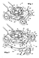
- Fig. 1 einen Handrasenmäher mit vier unverschwenkbar gelagerten Rädern,
- Fig. 2 einen Handrasenmäher mit zwei unverschwenkbar gelagerten rückwärtigen Laufrädern und zwei vorderen verschwenkbar gelagerten Rädern teilweise in auseinandergezogener Darstellung,
- Fig. 3 einen umgerüsteten Handrasenmäher mit parallel verstelltem Gehäuse,
- Fig. 4 eine ähnliche Darstellung wie in Fig. 3, wobei sich jedoch der Stellmechanismus an der Vorderseite des Gehäuses in einer Position befindet, daß die Vorderkante des Gehäuses am weitesten nach unten abgesenkt ist, und
- Fig. 5 einen Schnitt entlang der Linie 5 - 5 gemäß Fig. 4.
- 1 is a hand lawn mower with four non-pivoting wheels,
- 2 a hand lawn mower with two non-pivoting rear wheels and two front pivotably mounted wheels, partly in an exploded view,
- 3 shows a converted hand-held lawn mower with a housing adjusted in parallel,
- Fig. 4 is a similar view as in Fig. 3, but with the adjusting mechanism on the front of the housing in a position that the front edge of the housing is lowered most downward, and
- 5 shows a section along the line 5 - 5 according to FIG. 4.
In Fig. 1 ist ein repräsentativer Handrasenmäher 10 mit unverschwenkbaren Laufrädern 24 und 28 dargestellt, der ein Gehäuse 12 für ein umlaufendes Messer und einen Oberteil 14 aufweist, auf dem ein Motor 16 mit einer vertikalen Welle angeordnet ist, die das Mähmesser 18 aufnimmt. Das herkömmliche Gehäuse 12 weist einen Schurz 20 auf, der die Bewegungsbahn des Mähmessers 18 abdeckt und der mit einer unteren Kante 22 versehen ist, die unterhalb der Bewegungsbahn des Messers liegt. Das Gehäuse 12 selbst ist, wie aus Fig. 1 hervorgeht, auf zwei rückwärtigen unverschwenkbar gelagerten Laufrädern 24 angeordnet, die über eine Einstellvorrichtung 26 verstellt werden können, sowie auf zwei vorderen unverschwenkbar angeordneten Laufrädern 28, die über eine Einstellvorrichtung 30 höhenverstellt werden können. Beide Einstellvorrichtungen sind herkömmlicher Art, und eine ins einzelne gehende Beschreibung scheint nicht erforderlich zu sein.In Fig. 1, a representative
Wie aus den Figuren 1 und 2 hervorgeht, ist zum Befestigen der unverschwenkbaren vorderen Laufräder 28 und für die Vertikalverstellung eine stangenförmige Achse 32 mit einem mittigen U-förmigen Teil 34, der einen rechten Schenkel 36 aufweist, der mit dem anderen Ende eines quer verlaufenden Befestigungsteils verbunden ist, der sich wiederum an das äußere Ende eines Kurbelteils 40 anschließt, vorgesehen. Der Kurbelteil 40 hat einen nach außen gebogenen Endteil 42, auf dem das rechte vordere Laufrad drehbar gelagert ist. In ähnlicher Weise weist der U-Teil 34 einen linken Schenkel 44 auf, der mit dem hinteren Ende eines quer verlaufenden Befestigungsteils 46 verbunden ist, dessen äußeres Ende wiederum mit einem Kurbelteil 47 in Verbindung steht. Auch der Kurbelteil 47 hat einen nach Außen gebogenen Endteil 48 (Fig. 3 und 4), an dem das linke vordere Laufrad drehbar angeordnet ist. Die Befestigungsteile 38 und 46 der Achse 32 sind axial zueinander ausgerichtet und über in der Zeichnung nicht dargestellte rechte und linke Laschen mit dem Gehäuse schwenkbar verbunden.As can be seen from FIGS. 1 and 2, a rod-
Wie am besten aus den Figuren 3 und 4 zu ersehen ist, weist die Einstellvorrichtung 30 einen vertikalen, segmentartig ausgebildeten Ansatz 54, der zu der linken Frontseite des Gehäuses 12 gehört, und eine Vielzahl von zueinander Abstand aufweisenden Rasternuten 56 auf, die bogenförmig angeordnet sind an der äußeren Oberfläche. An die Achse 32 greift in dem Bereich, in dem sich der Befestigungsteil 46 und der Kurbelteil 47 treffen, ein Hebel 58 an, der vorzugsweise federnd ausgebildet ist und einen Zapfen 60 aufnimmt, der in eine der Rasternuten 56 eingreifen kann und damit die Achse 32 in verschiedenen Winkelpositionen feststellen kann. Auf diese Weise können die Laufräder 28 in verschiedenen Vertikalpositionen mit Bezug auf das Gehäuse eingestellt werden. Eine derartige Verstellung der vorderen Laufräder 28 wird natürlich nicht ohne eine Verstellung der rückwärtigen Laufräder durchgeführt, damit die Schnitthöhe des Mähmessers 18 richtig eingestellt werden kann. Im einzelnen wird das Mähmesser 18 seine höchste Schnitthöhe einnehmen, wenn der Hebel 58 die mit A gekennzeichnete Position einnimmt. Die Schnitthöhe des Mähmessers nimmt ab, wenn der Hebel im Uhrzeigerdrehsinn in eine andere Endstellung, die mit F bezeichnet ist, verschwenkt wird. Der U-Teil 34 der Achse 32 dient zusätzlich als Sicherheitsbügel, der verhindert, daß ein Fuß der Bedienungsperson zu nah an das vordere Ende des Gehäuses und damit eventuell in Kontakt mit dem Mähmesser kommt. Einzelheiten einer solchen Konstruktion sind in dem Dokument US-A-4 224 785 ersichtlich.As can best be seen from FIGS. 3 and 4, the adjusting
Beim vorliegenden Ausführungsbeispiel ist die Erfindung an einem Handrasenmäher dargestellt, der die vorstehend beschriebene Frontachse aufweist. Selbstverständlich kann die Erfindung auch an anderen Handrasenmähern angewendet werden, wobei eine Höhenverstellung nicht unbedingt sein muß und es auch durchaus denkbar ist, daß sich der Rasenmäher nur auf drei Laufrädern, beispielsweise einem vorderen und zwei rückwärtigen, abstützt.In the present embodiment, the invention is shown on a hand lawn mower that has the front axis described above. Of course, the invention can also be applied to other hand lawn mowers, whereby a height adjustment is not absolutely necessary and it is also quite conceivable that the lawn mower is supported only on three wheels, for example one front and two rear.
Die Manövrierfähigkeit eines derartigen Handrasenmähers, der vier unverschwenkbare Laufräder aufweist, ist natürlich nicht groß, und über die erfindungsgemäße Umrüstung wird eine bessere Manövrierfähigkeit erreicht, so daß Kurven von 180° leicht durchfahren werden können, ohne daß die Bedienungsperson beide Hände benötigt und wobei darüber hinaus die Grasnarbe nicht durch die unverschwenkbaren Räder verletzt wird. Die erfindungsgemäße Umrüstung ermöglicht es ferner, daß die Schnitthöhe nicht verändert wird und daß darüber hinaus eine Höhenverstellung, sofern sie an dem Handrasenmäher vorgesehen ist, nach wie vor durchgeführt werden kann. Im einzelnen sieht die Erfindung hierzu einen Umbausatz 80 vor, durch den die beiden vorderen unverschwenkbar gelagerten Laufräder 28 ersetzt werden. Der Umbausatz 80 besteht im einzelnen aus zwei Pendelradsätzen 82 und 84 mit Pendelrädern 86 und 88, die in Halterungen 90 und 92 gelagert sind, die wiederum in Rahmenteilen 94 und 96 um vertikale Achsen schwenkbar sind. Jeder Rahmenteil 94, 96 ist mit einer Öffnung 100 versehen, in der später noch zu beschreibende Komponenten aufgenommen werden können.The maneuverability of such a hand lawnmower, which has four non-pivoting wheels, is of course not great, and better maneuverability is achieved via the retrofitting according to the invention, so that curves of 180 ° can be easily negotiated without the operator needing both hands and in addition the turf is not injured by the unmovable wheels. The retrofitting according to the invention also makes it possible that the cutting height is not changed and that a height adjustment, provided that it is provided on the hand lawn mower, can still be carried out. In detail, the invention provides for this a
Jeder Pendelradsatz 82 und 84 ist mit Verbindungsteilen 106 und 108, die sich im wesentlichen in Längsrichtung erstrecken, versehen, wobei sich diese Verbindungsteile 106 und 108 in etwa über die gesamte Länge des Handrasenmähers 10 zwischen den Rahmenteilen 94 und 96, mit denen sie verbunden sind, und den entsprechenden Enden einer hinteren Achse 110 erstrecken. An den Enden 112 der Verbindungsteile 106 und 108 sind offene, U-förmig ausgebildete Schlitze 114 vorgesehen. Jeder Verbindungsteil 106 und 108 ist so ausgebildet, daß er der Kontur des Gehäuses 12 folgen kann.Each pendulum wheel set 82 and 84 is provided with connecting
Bekanntlich ist es zur Funktion eines Pendelrades wichtig, daß seine vertikale Welle senkrecht zu einer Auflagefläche oder der Bodenoberfläche 111 verläuft, und im Falle der Verwendung von Pendelrädern 86 und 88 an einem Handrasenmäher 10 ist es wichtig, daß im eingebauten Zustand die vertikalen Achsen 83 und 85 der Pendelräder immer senkrecht zur Bodenoberfläche 111 verbleiben. Um das zu erreichen, ist es wichtig, daß die Mitte oder die Achse eines jeden Laufrades 24 oder der Pendelräder 86 und 88 den gleichen Abstand von der Bodenoberfläche 111 aufweist, so daß in jeder Höhenstellung das Mähmesser 18 parallele Mähkreise mit Bezug auf die Bodenoberfläche 111 beschreibt. Durch die Verbindung der vorderen und rückwärtigen Achse über die Verbindungsteile 106 und 108 verbleiben die vertikalen Achsen 83 und 85 der beiden Pendelräder 86 und 88 immer senkrecht zu der Bodenoberfläche 111, wenn immer die Schnitthöhe geändert wird und die beiden vorderen und rückwärtigen Laufräder mit Bezug auf das Gehäuse verstellt werden.As is known, for the function of a pendulum wheel it is important that its vertical shaft is perpendicular to a bearing surface or the ground surface 111, and in the case of the use of
Falls erforderlich, kann noch eine Haltestange 116 zur Verbindung zwischen den beiden Pendelradsätzen 82 und 84 vorgesehen werden, wodurch der Umbausatz im Einbau seine erforderliche Stabilität erhält und außerdem ein konstanter Abstand zwischen den Rahmenteilen 94 und 96 eingehalten wird.If necessary, a holding
Zur Vorbereitung eines herkömmlichen Handrasenmähers 10 zur Aufnahme des Umbausatzes 80 kann es noch wünschenswert sein, Nuten 120 in den beiden Enden der rückwärtigen Achse vorzusehen.To prepare a
Das Verfahren zur Umrüstung eines herkömmlichen Handrasenmähers 10 mit unverschwenkbaren vorderen Laufrädern 28 in einen mit Pendelrädern nach der Erfindung erfordert in der Regel nur wenige Minuten, beispielsweise zwei. Um die Umrüstung durchzuführen, wird die rückwärtige Achse 110 etwas modifiziert, um die U-förmigen Schlitze 114 der Verbindungsteile 106 und 108 aufnehmen zu können. Dies kann in einfacher Weise dadurch gemacht werden, daß man den Durchmesser der Enden der rückwärtigen Achse reduziert, so daß sie in etwa der Höhe des Schlitzes 114 entsprechen. Andererseits ist es durchaus zweckmäßig, entsprechende Nuten 120 vorzusehen. Ist ein Handrasenmäher so modifiziert worden, dann können die linken und rechten vorderen Laufräder 28 entfernt werden, wonach die beiden Verbindungsteile 106 und 108 mit der rückwärtigen Achse durch Einführen des Schlitzes 114 über die Nut 120 verbunden werden. Danach werden die Rahmenteile 94 und 96 mit der vorderen Achse 32 durch Einführen der Endstücke 42 und 48 in die Öffnungen 100 verbunden. Selbstverständlich wird zunächst nur der Rahmenteil an einer Seite mit den entsprechenden Gegenteilen verbunden und nachfolgend der Rahmenteil an der anderen Seite. Wird die Haltestange 116 noch für erforderlich gehalten, so muß sie ebenfalls eingesetzt werden. Eine Sicherung der Haltestange als auch der Endteile der vorderen Achse 32 erfolgt über entsprechende Muttern 126. Zur Aufnahme der Haltestange 116 in den Rahmenteilen 94 und 96 sind entsprechende Öffnungen 102 vorgesehen.The method for converting a conventional
Im ganzen gesehen wird hiermit ein äußerst einfacher Vorschlag zur Umrüstung eines Handrasenmähers mit unverschwenkbaren Laufrädern in einen solchen mit verschwenkbaren Laufrädern gemacht, wobei selbstverständlich ein derart umgerüsteter Handrasenmäher auch wieder schnell zurückgerüstet werden kann. Hierbei verlaufen dann die einzelnen Verfahrensschritte umgekehrt.Seen as a whole, an extremely simple proposal for converting a hand lawn mower with non-swiveling wheels into one with swiveling wheels is made, whereby of course such a hand lawn mower converted in this way can also be quickly retrofitted. The individual process steps are then reversed.
Claims (13)
Applications Claiming Priority (2)
| Application Number | Priority Date | Filing Date | Title |
|---|---|---|---|
| US9064887A | 1987-08-28 | 1987-08-28 | |
| US90648 | 1993-07-12 |
Publications (2)
| Publication Number | Publication Date |
|---|---|
| EP0304903A1 true EP0304903A1 (en) | 1989-03-01 |
| EP0304903B1 EP0304903B1 (en) | 1991-10-30 |
Family
ID=22223677
Family Applications (1)
| Application Number | Title | Priority Date | Filing Date |
|---|---|---|---|
| EP19880113821 Expired - Lifetime EP0304903B1 (en) | 1987-08-28 | 1988-08-25 | Hand lawn mower adjustable in height |
Country Status (3)
| Country | Link |
|---|---|
| EP (1) | EP0304903B1 (en) |
| CA (1) | CA1303364C (en) |
| DE (1) | DE3865926D1 (en) |
Cited By (9)
| Publication number | Priority date | Publication date | Assignee | Title |
|---|---|---|---|---|
| EP0367891A1 (en) * | 1988-11-07 | 1990-05-16 | Deere & Company | Hand-operated lawn mower |
| EP0478020A2 (en) * | 1990-08-30 | 1992-04-01 | Castelgarden S.P.A. | Lawn mower with support roller and rear wheels ajustable in different cutting positions |
| FR2679103A1 (en) * | 1991-07-18 | 1993-01-22 | Delery Creations | LAWN MOWER. |
| GB2481109A (en) * | 2010-06-09 | 2011-12-14 | Chervon Hk Ltd | Lawn care apparatus |
| GB2494242A (en) * | 2011-09-01 | 2013-03-06 | Skybest Electric Appliance Suzhou Co Ltd | Height adjust mechanism for a lawnmower |
| US20140083072A1 (en) * | 2011-05-31 | 2014-03-27 | Husqvarna Ab | Height adjustment arrangement for a lawn mower |
| WO2019149229A1 (en) * | 2018-01-30 | 2019-08-08 | 苏州宝时得电动工具有限公司 | Grass trimmer |
| SE2050200A1 (en) * | 2019-12-04 | 2021-06-05 | Husqvarna Ab | Lawnmower |
| WO2021110414A1 (en) * | 2019-12-04 | 2021-06-10 | Husqvarna Ab | Lawnmower |
Citations (4)
| Publication number | Priority date | Publication date | Assignee | Title |
|---|---|---|---|---|
| FR2028438A1 (en) * | 1969-01-16 | 1970-10-09 | Mowbot Inc | |
| GB2054333A (en) * | 1979-07-31 | 1981-02-18 | Firth Cleveland Ltd | Mowing machine |
| US4313295A (en) * | 1980-02-11 | 1982-02-02 | Outboard Marine Corporation | Blade housing mount for riding mowers |
| US4558558A (en) * | 1984-07-31 | 1985-12-17 | The Toro Company | Lawn mower traction control system |
-
1988
- 1988-08-25 EP EP19880113821 patent/EP0304903B1/en not_active Expired - Lifetime
- 1988-08-25 DE DE8888113821T patent/DE3865926D1/en not_active Expired - Fee Related
- 1988-08-26 CA CA000575758A patent/CA1303364C/en not_active Expired - Lifetime
Patent Citations (4)
| Publication number | Priority date | Publication date | Assignee | Title |
|---|---|---|---|---|
| FR2028438A1 (en) * | 1969-01-16 | 1970-10-09 | Mowbot Inc | |
| GB2054333A (en) * | 1979-07-31 | 1981-02-18 | Firth Cleveland Ltd | Mowing machine |
| US4313295A (en) * | 1980-02-11 | 1982-02-02 | Outboard Marine Corporation | Blade housing mount for riding mowers |
| US4558558A (en) * | 1984-07-31 | 1985-12-17 | The Toro Company | Lawn mower traction control system |
Cited By (16)
| Publication number | Priority date | Publication date | Assignee | Title |
|---|---|---|---|---|
| EP0367891A1 (en) * | 1988-11-07 | 1990-05-16 | Deere & Company | Hand-operated lawn mower |
| EP0478020A2 (en) * | 1990-08-30 | 1992-04-01 | Castelgarden S.P.A. | Lawn mower with support roller and rear wheels ajustable in different cutting positions |
| EP0478020A3 (en) * | 1990-08-30 | 1993-04-07 | Castel Garden Equipment S.P.A. | Lawn mower with support roller and rear wheels ajustable in different cutting positions |
| FR2679103A1 (en) * | 1991-07-18 | 1993-01-22 | Delery Creations | LAWN MOWER. |
| WO1993001706A1 (en) * | 1991-07-18 | 1993-02-04 | Creations Delery S.A.R.L | Lawn mower |
| US5426926A (en) * | 1991-07-18 | 1995-06-27 | Creations Delery & S.A. Kubota Europe | Lawnmower |
| GB2481109A (en) * | 2010-06-09 | 2011-12-14 | Chervon Hk Ltd | Lawn care apparatus |
| GB2481109B (en) * | 2010-06-09 | 2016-10-12 | Chervon (Hk) Ltd | Lawn care apparatus |
| US20140083072A1 (en) * | 2011-05-31 | 2014-03-27 | Husqvarna Ab | Height adjustment arrangement for a lawn mower |
| US10470363B2 (en) * | 2011-05-31 | 2019-11-12 | Husqvarna Ab | Height adjustment arrangement for a lawn mower |
| GB2494242B (en) * | 2011-09-01 | 2016-05-04 | Skybest Electric Appliance Suzhou Co Ltd | Lawnmower |
| GB2494242A (en) * | 2011-09-01 | 2013-03-06 | Skybest Electric Appliance Suzhou Co Ltd | Height adjust mechanism for a lawnmower |
| WO2019149229A1 (en) * | 2018-01-30 | 2019-08-08 | 苏州宝时得电动工具有限公司 | Grass trimmer |
| SE2050200A1 (en) * | 2019-12-04 | 2021-06-05 | Husqvarna Ab | Lawnmower |
| WO2021110414A1 (en) * | 2019-12-04 | 2021-06-10 | Husqvarna Ab | Lawnmower |
| SE544276C2 (en) * | 2019-12-04 | 2022-03-22 | Husqvarna Ab | Lawnmower |
Also Published As
| Publication number | Publication date |
|---|---|
| EP0304903B1 (en) | 1991-10-30 |
| DE3865926D1 (en) | 1991-12-05 |
| CA1303364C (en) | 1992-06-16 |
Similar Documents
| Publication | Publication Date | Title |
|---|---|---|
| EP0367891B1 (en) | Hand-operated lawn mower | |
| DE3343005A1 (en) | TOW ROD FOR MOUNTING TOOL MOUNTING APPLICABLE TO THE GROUND CONTOUR | |
| EP0304903B1 (en) | Hand lawn mower adjustable in height | |
| DE102015207684A1 (en) | MECHANISM FOR ADJUSTING THE CUTTING HEIGHT OF A ROTATION CUTTING DEVICE | |
| DE2117666A1 (en) | Group mower with self-sharpening device | |
| EP0518171B1 (en) | Vertically adjustable depth adjusting means, with a sliding shoe | |
| DE2730171A1 (en) | DEVICE FOR MOWING OR CUTTING PLANT GROWTH AND CUTTING HEAD FOR IT | |
| WO2008095715A2 (en) | Height-adjustable lawn mower and base for lawn mower | |
| DE2707496A1 (en) | AGRICULTURAL MACHINE OF THE MACHINE OR FLAIL MOWER TYPE WITH SWIVELING BOX FRAME | |
| DE2208603A1 (en) | Floor cleaning device with friction wheel drive | |
| DE3211579A1 (en) | Rotary swath rake | |
| DE3316204A1 (en) | Device for varying or adjusting the cutting height of a tractor-drawn rotary mower equipped especially with rotating drums fitted with cutters | |
| DE102006028127B4 (en) | implement | |
| DE3644273A1 (en) | ROTARY MOWER | |
| DE3507043C2 (en) | ||
| EP0685148A1 (en) | Mowing and/or aerating machine | |
| DE69934579T2 (en) | MOVEMENT PROCESS FOR LAWN MOWER | |
| DE60218014T2 (en) | Insertable and removable mower unit for lawnmowers | |
| DE19604758A1 (en) | Rotor with wire loops for pruning fruit trees | |
| DE3134390A1 (en) | MOWER | |
| DE3729624A1 (en) | Mobile reaper, especially for agricultural and forestry purposes | |
| DE7925367U1 (en) | Harrow with drivable tines | |
| DE2543231A1 (en) | Mobile, hand-operated grass-mower - is electrically driven by portable tool, e.g. electric drill | |
| DE3348303C2 (en) | Rotary mower cutting height adjustment | |
| DE3943125A1 (en) | Hand operated rotary lawn mower - has extra side-cutter for simultaneously cutting mother strip |
Legal Events
| Date | Code | Title | Description |
|---|---|---|---|
| PUAI | Public reference made under article 153(3) epc to a published international application that has entered the european phase |
Free format text: ORIGINAL CODE: 0009012 |
|
| AK | Designated contracting states |
Kind code of ref document: A1 Designated state(s): DE FR GB SE |
|
| 17P | Request for examination filed |
Effective date: 19890114 |
|
| 17Q | First examination report despatched |
Effective date: 19900814 |
|
| GRAA | (expected) grant |
Free format text: ORIGINAL CODE: 0009210 |
|
| AK | Designated contracting states |
Kind code of ref document: B1 Designated state(s): DE FR GB SE |
|
| REF | Corresponds to: |
Ref document number: 3865926 Country of ref document: DE Date of ref document: 19911205 |
|
| GBT | Gb: translation of ep patent filed (gb section 77(6)(a)/1977) | ||
| ET | Fr: translation filed | ||
| PLBE | No opposition filed within time limit |
Free format text: ORIGINAL CODE: 0009261 |
|
| STAA | Information on the status of an ep patent application or granted ep patent |
Free format text: STATUS: NO OPPOSITION FILED WITHIN TIME LIMIT |
|
| 26N | No opposition filed | ||
| PGFP | Annual fee paid to national office [announced via postgrant information from national office to epo] |
Ref country code: GB Payment date: 19930701 Year of fee payment: 6 |
|
| PGFP | Annual fee paid to national office [announced via postgrant information from national office to epo] |
Ref country code: FR Payment date: 19930811 Year of fee payment: 6 |
|
| PGFP | Annual fee paid to national office [announced via postgrant information from national office to epo] |
Ref country code: SE Payment date: 19930825 Year of fee payment: 6 |
|
| PGFP | Annual fee paid to national office [announced via postgrant information from national office to epo] |
Ref country code: DE Payment date: 19931018 Year of fee payment: 6 |
|
| PG25 | Lapsed in a contracting state [announced via postgrant information from national office to epo] |
Ref country code: GB Effective date: 19940825 |
|
| PG25 | Lapsed in a contracting state [announced via postgrant information from national office to epo] |
Ref country code: SE Effective date: 19940826 |
|
| EAL | Se: european patent in force in sweden |
Ref document number: 88113821.8 |
|
| GBPC | Gb: european patent ceased through non-payment of renewal fee |
Effective date: 19940825 |
|
| PG25 | Lapsed in a contracting state [announced via postgrant information from national office to epo] |
Ref country code: FR Effective date: 19950428 |
|
| PG25 | Lapsed in a contracting state [announced via postgrant information from national office to epo] |
Ref country code: DE Effective date: 19950503 |
|
| EUG | Se: european patent has lapsed |
Ref document number: 88113821.8 |
|
| REG | Reference to a national code |
Ref country code: FR Ref legal event code: ST |