EP0459183A1 - Control device - Google Patents
Control device Download PDFInfo
- Publication number
- EP0459183A1 EP0459183A1 EP19910107375 EP91107375A EP0459183A1 EP 0459183 A1 EP0459183 A1 EP 0459183A1 EP 19910107375 EP19910107375 EP 19910107375 EP 91107375 A EP91107375 A EP 91107375A EP 0459183 A1 EP0459183 A1 EP 0459183A1
- Authority
- EP
- European Patent Office
- Prior art keywords
- control
- housing
- transmitter according
- shift rod
- control transmitter
- Prior art date
- Legal status (The legal status is an assumption and is not a legal conclusion. Google has not performed a legal analysis and makes no representation as to the accuracy of the status listed.)
- Granted
Links
Images


Classifications
-
- G—PHYSICS
- G05—CONTROLLING; REGULATING
- G05G—CONTROL DEVICES OR SYSTEMS INSOFAR AS CHARACTERISED BY MECHANICAL FEATURES ONLY
- G05G5/00—Means for preventing, limiting or returning the movements of parts of a control mechanism, e.g. locking controlling member
- G05G5/03—Means for enhancing the operator's awareness of arrival of the controlling member at a command or datum position; Providing feel, e.g. means for creating a counterforce
-
- G—PHYSICS
- G05—CONTROLLING; REGULATING
- G05G—CONTROL DEVICES OR SYSTEMS INSOFAR AS CHARACTERISED BY MECHANICAL FEATURES ONLY
- G05G9/00—Manually-actuated control mechanisms provided with one single controlling member co-operating with two or more controlled members, e.g. selectively, simultaneously
- G05G9/02—Manually-actuated control mechanisms provided with one single controlling member co-operating with two or more controlled members, e.g. selectively, simultaneously the controlling member being movable in different independent ways, movement in each individual way actuating one controlled member only
- G05G9/04—Manually-actuated control mechanisms provided with one single controlling member co-operating with two or more controlled members, e.g. selectively, simultaneously the controlling member being movable in different independent ways, movement in each individual way actuating one controlled member only in which movement in two or more ways can occur simultaneously
- G05G9/047—Manually-actuated control mechanisms provided with one single controlling member co-operating with two or more controlled members, e.g. selectively, simultaneously the controlling member being movable in different independent ways, movement in each individual way actuating one controlled member only in which movement in two or more ways can occur simultaneously the controlling member being movable by hand about orthogonal axes, e.g. joysticks
- G05G2009/04703—Mounting of controlling member
- G05G2009/04707—Mounting of controlling member with ball joint
-
- G—PHYSICS
- G05—CONTROLLING; REGULATING
- G05G—CONTROL DEVICES OR SYSTEMS INSOFAR AS CHARACTERISED BY MECHANICAL FEATURES ONLY
- G05G9/00—Manually-actuated control mechanisms provided with one single controlling member co-operating with two or more controlled members, e.g. selectively, simultaneously
- G05G9/02—Manually-actuated control mechanisms provided with one single controlling member co-operating with two or more controlled members, e.g. selectively, simultaneously the controlling member being movable in different independent ways, movement in each individual way actuating one controlled member only
- G05G9/04—Manually-actuated control mechanisms provided with one single controlling member co-operating with two or more controlled members, e.g. selectively, simultaneously the controlling member being movable in different independent ways, movement in each individual way actuating one controlled member only in which movement in two or more ways can occur simultaneously
- G05G9/047—Manually-actuated control mechanisms provided with one single controlling member co-operating with two or more controlled members, e.g. selectively, simultaneously the controlling member being movable in different independent ways, movement in each individual way actuating one controlled member only in which movement in two or more ways can occur simultaneously the controlling member being movable by hand about orthogonal axes, e.g. joysticks
- G05G2009/0474—Manually-actuated control mechanisms provided with one single controlling member co-operating with two or more controlled members, e.g. selectively, simultaneously the controlling member being movable in different independent ways, movement in each individual way actuating one controlled member only in which movement in two or more ways can occur simultaneously the controlling member being movable by hand about orthogonal axes, e.g. joysticks characterised by means converting mechanical movement into electric signals
- G05G2009/04748—Position sensor for rotary movement, e.g. potentiometer
-
- G—PHYSICS
- G05—CONTROLLING; REGULATING
- G05G—CONTROL DEVICES OR SYSTEMS INSOFAR AS CHARACTERISED BY MECHANICAL FEATURES ONLY
- G05G9/00—Manually-actuated control mechanisms provided with one single controlling member co-operating with two or more controlled members, e.g. selectively, simultaneously
- G05G9/02—Manually-actuated control mechanisms provided with one single controlling member co-operating with two or more controlled members, e.g. selectively, simultaneously the controlling member being movable in different independent ways, movement in each individual way actuating one controlled member only
- G05G9/04—Manually-actuated control mechanisms provided with one single controlling member co-operating with two or more controlled members, e.g. selectively, simultaneously the controlling member being movable in different independent ways, movement in each individual way actuating one controlled member only in which movement in two or more ways can occur simultaneously
- G05G9/047—Manually-actuated control mechanisms provided with one single controlling member co-operating with two or more controlled members, e.g. selectively, simultaneously the controlling member being movable in different independent ways, movement in each individual way actuating one controlled member only in which movement in two or more ways can occur simultaneously the controlling member being movable by hand about orthogonal axes, e.g. joysticks
- G05G2009/04766—Manually-actuated control mechanisms provided with one single controlling member co-operating with two or more controlled members, e.g. selectively, simultaneously the controlling member being movable in different independent ways, movement in each individual way actuating one controlled member only in which movement in two or more ways can occur simultaneously the controlling member being movable by hand about orthogonal axes, e.g. joysticks providing feel, e.g. indexing means, means to create counterforce
- G05G2009/0477—Manually-actuated control mechanisms provided with one single controlling member co-operating with two or more controlled members, e.g. selectively, simultaneously the controlling member being movable in different independent ways, movement in each individual way actuating one controlled member only in which movement in two or more ways can occur simultaneously the controlling member being movable by hand about orthogonal axes, e.g. joysticks providing feel, e.g. indexing means, means to create counterforce holding the member in a number of definite positions
-
- Y—GENERAL TAGGING OF NEW TECHNOLOGICAL DEVELOPMENTS; GENERAL TAGGING OF CROSS-SECTIONAL TECHNOLOGIES SPANNING OVER SEVERAL SECTIONS OF THE IPC; TECHNICAL SUBJECTS COVERED BY FORMER USPC CROSS-REFERENCE ART COLLECTIONS [XRACs] AND DIGESTS
- Y10—TECHNICAL SUBJECTS COVERED BY FORMER USPC
- Y10T—TECHNICAL SUBJECTS COVERED BY FORMER US CLASSIFICATION
- Y10T74/00—Machine element or mechanism
- Y10T74/20—Control lever and linkage systems
- Y10T74/20012—Multiple controlled elements
- Y10T74/20201—Control moves in two planes
-
- Y—GENERAL TAGGING OF NEW TECHNOLOGICAL DEVELOPMENTS; GENERAL TAGGING OF CROSS-SECTIONAL TECHNOLOGIES SPANNING OVER SEVERAL SECTIONS OF THE IPC; TECHNICAL SUBJECTS COVERED BY FORMER USPC CROSS-REFERENCE ART COLLECTIONS [XRACs] AND DIGESTS
- Y10—TECHNICAL SUBJECTS COVERED BY FORMER USPC
- Y10T—TECHNICAL SUBJECTS COVERED BY FORMER US CLASSIFICATION
- Y10T74/00—Machine element or mechanism
- Y10T74/20—Control lever and linkage systems
- Y10T74/20576—Elements
- Y10T74/20636—Detents
Definitions
- the invention relates to a control transmitter according to the preamble of the main claim.
- Such known control transmitters are probably simple in construction, but no longer meet the requirements for a more advanced technology.
- control transmitter according to the invention with the characterizing features of the main claim has the advantage that it brings a significant improvement in function with only slightly higher effort and is therefore particularly well suited for special cases.
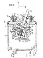
- FIG. 1 a longitudinal section through a control transmitter
- FIGS. 2A to 2D an individual part in the different views (locking plate)
- FIG. 3 a section through a housing part
- FIG. 4 a plan view of the housing part according to FIG. 3
- FIG. 5 a side view of the control transmitter
- FIG. 6 an application for the control transmitter.
- 10 denotes the approximately cup-shaped housing of a control transmitter, on the open upper part of which a control housing 11 is arranged, which in turn is closed by a link 12.
- the control housing 11 has an open extension 13 with a square cross section, which projects far into the housing 10 and on the lower side of which a locking plate 14 is fastened.
- the backdrop 12 there is a backdrop 15 for a shift rod 16 which projects into the housing to the end of the extension 13, i. H. to the locking plate 14.
- the shift rod 16 is mounted in a ball joint 17, which is part of a funnel-like extension 18 which extends downwards, ie. H. to the locking plate 14 approximately conically narrowed and ends in the ball joint 17.
- the shape of the extension 18 is strongly conical and slightly curved in the lower part 18A, which then follows upwards to an annular groove-like recess 18B, which is followed by a region 18C which is again strongly conical, which then flattens out and in a cylindrical end part 18D ends.
- the entire contour described is circular.
- the part of the shift rod located below the ball joint 17 is in operative connection with two deflection brackets 24, 25, which are pivotably mounted in the extension 13 of the control housing 11 at right angles to one another. Only the control bracket 24 is described, since the control bracket 25 is designed and mounted in the same way.
- the pin 27 of a rotary angle sensor 28 (potentiometer) is mounted, the pin 27 being followed by a further pin 32 with a much smaller diameter, which projects into the control housing, specifically into the space between the extension 13 and the extension 18.
- the pin 32 has a flattened area 29, against which a pin 30 rests, which is inserted into a bore 31 of the bracket 24.
- the control bracket 24 has a longitudinal slot 36 through which the lower part 16A of the shift rod passes.
- a slide bush 37 is mounted on the shift rod, which is fixed on both sides by snap rings 38.
- a pressure pin 39 protrudes with its shaft 40 into a longitudinal bore 41 of the shift rod, in which a pressure spring 42 is arranged, which presses the pressure pin 39 against the locking plate 14, which is discussed further below.
- the control bracket 25 is designed in exactly the same way as the control bracket 24. Through its longitudinal slot 44, which corresponds to the longitudinal slot 36 in the switching bracket 24, the switching lever 16 penetrates this control bracket in the region of the sliding bush 37. The switching lever 16 is bound in this sliding bracket around the spherical plain bearing 17 pivotable in a plane X, which runs perpendicular to the plane Y.
- the latching plate 14 for which reference is also made to FIGS. 2a to 2d, has in its center and facing the shift rod a surface 46 which is part of a spherical surface, the center of which lies in the axis of the shift rod 16 when the latter is in a precisely vertical central position located.
- the surface 46 extends far outwards and has a square shape as seen from above - see FIG. 2C. It ends at an all-round and sloping edge 47, which in turn merges into an outer surface 48, which also has a spherical surface shape and runs centrally to surface 46. Diagonal grooves 49 extend from the corner points of surface 46. It should also be noted that the locking plate 14 is of course firmly arranged on the extension 13 of the control housing 11.
- a rubber hood 50 is attached between the link 12 and the control housing 11 and covers the entire control transmitter in a sealed manner towards the switching rod 16.
- the setting 12 is connected to the control part 11 by means of screws 51.
- a cable harness plug 53 is installed in the lower opening 52 of the housing 10, as shown in FIG.
- the two potentiometers - of which only the potentiometer 28 is shown - are adjustable from the outside. For this purpose, reference is made to FIGS. 3 and 4.
- a knurled nut 54 is located in a flange of the housing, with the aid of which the potentiometer 28 can be set to a specific desired value. With a second knurled nut 55, the rotary angle sensor actuated by the control bracket 25 can be adjusted.
- the control transmitter according to the invention is particularly suitable for actuating two proportional magnets 57, 58 of a directional control valve 59, with the aid of which a working cylinder 60 is controlled, see FIG. 6.
- the control transmitter or the switching rod 16 can be deflected simultaneously in the directions of the two main axes X, Y.
- the slide 19 slides along the shift rod and with its outer contour on the curved conical contour 18A to 18C of the control housing 11.
- the steep edge 18C is formed, so that when a certain deflection angle in the X or Y direction is reached, the actuating force increases due to the increased frictional force on Slider is achieved. This means that the person operating the device has a good feeling for the size of the deflection.
- the speed of the hydraulic actuators - in this case the working cylinder - is optimally adapted to the respective different work processes.
- the setting option is achieved via the rotary encoder.
- the change in resistance causes a change in the sensitivity of the electronics, which has an effect on the size of the electrical current for controlling the proportional valves 57 and 58 at a certain deflection angle of the shift rod, which is decisive for the deflection of the control slide in the directional control valve and thus for the volume flow in the working cylinder 60 .
- the arrangement of the two potentiometers is selected so that a secure assignment for both axes is guaranteed and unintentional adjustment is avoided.
- the potentiometers are set via the knurled disks 54, 55 - see FIGS. 3 and 4.
- the control transmitter After reaching or exceeding a certain deflection angle of the shift rod, the control transmitter should remain deflected at this certain angle after release of the same (detent position) and only be brought out of this detent position with an increased force applied in the direction of the rest position. This is achieved with the aid of the locking plate 14 and the pressure pin 39.
- the pressure pin slides from the inner spherical surface 46 to the outer spherical surface 48 when a certain deflection angle of the shift rod is reached or exceeded.
- the prestressing of the pressure bolt 39 is sufficient to compensate for the restoring forces of the spring 20 counteract via the slider 19. When the specific deflection angle is exceeded in both axes, the pressure pin is guided and held in this position by the grooves 49 on the locking plate.
Abstract
Description
Die Erfindung geht aus von einem Steuergeber nach der Gattung des Hauptanspruchs. Derartige bekannte Steuergeber sind wohl einfach im Aufbau, genügen jedoch nicht mehr den Anforderungen an eine fortschrittlichere Technik.The invention relates to a control transmitter according to the preamble of the main claim. Such known control transmitters are probably simple in construction, but no longer meet the requirements for a more advanced technology.
Der erfindungsgemäße Steuergeber mit den kennzeichnenden Merkmalen des Hauptanspruchs hat demgegenüber den Vorteil, daß er bei nur geringfügig höherem Aufwand eine wesentliche Funktionsverbesserung mit sich bringt und somit auch für Sonderfälle besonders gut geeignet ist.The control transmitter according to the invention with the characterizing features of the main claim has the advantage that it brings a significant improvement in function with only slightly higher effort and is therefore particularly well suited for special cases.
Besonders vorteilhafte Ausgestaltungen der Erfindung ergeben sich aus den Unteransprüchen.Particularly advantageous embodiments of the invention result from the subclaims.
Ein Ausführungsbeispiel der Erfindung ist in der nachfolgenden Beschreibung und Zeichnung wiedergegeben. Letztere zeigt in Figur 1 einen Längsschnitt durch einen Steuergeber, in den Figuren 2A bis 2D ein Einzelteil in den verschiedenen Ansichten (Rastplatte), in Figur 3 einen Schnitt durch ein Gehäuseteil, in Figur 4 einen Draufsicht auf das Gehäuseteil nach Figur 3, in Figur 5 eine Seitenansicht des Steuergebers und in Figur 6 eine Anwendungsmöglichkeit für den Steuergeber.An embodiment of the invention is shown in the following description and drawing. The latter is shown in FIG. 1 a longitudinal section through a control transmitter, in FIGS. 2A to 2D an individual part in the different views (locking plate), in FIG. 3 a section through a housing part, in FIG. 4 a plan view of the housing part according to FIG. 3, in FIG. 5 a side view of the control transmitter and in FIG. 6 an application for the control transmitter.
In Figur 1 ist mit 10 das etwa topfförmige Gehäuse eines Steuergebers bezeichnet, an dessen offenem oberen Teil ein Steuergehäuse 11 angeordnet ist, welches selbst wiederum durch eine Kulisse 12 verschlossen ist. Das Steuergehäuse 11 hat einen offenen, im Querschnitt quadratischen Fortsatz 13, welcher weit in das Gehäuse 10 hineinragt und an dessen unterer Seite eine Rastplatte 14 befestigt ist. In der Kulisse 12 befindet sich eine Kulisse 15 für eine Schaltstange 16, die bis an das Ende des Fortsatzes 13 in das Gehäuse hineinragt, d. h. bis zur Rastplatte 14. Die Schaltstange 16 ist in einem Kugelgelenk 17 gelagert, welches Teil eines trichterartigen Fortsatzes 18 ist, der sich nach unten, d. h. zur Rastplatte 14 etwa konisch verengt und im Kugelgelenk 17 endet. Die Form des Fortsatzes 18 ist im unteren Teil 18A stark konisch und leicht gewölbt, es folgt dann nach oben zu eine ringnutartige, umlaufende Einbuchtung 18B, worauf eine sich wiederum stark konisch gewölbte Zone 18C anschließt, die sich dann abflacht und in einem zylindrischen Endteil 18D endet. Die gesamte beschriebene Kontur ist kreisförmig ausgebildet.In FIG. 1, 10 denotes the approximately cup-shaped housing of a control transmitter, on the open upper part of which a
Oberhalb des Kugelgelenks 17 befindet sich verschiebbar an der Schaltstange 16 ein ringförmiges Gleitstück 19, auf welches eine Druckfeder 20 einwirkt, die sich an einem Federteller 21 abstützt, das mit Hilfe eines Sprengrings 22 an der Schaltstange befestigt ist und in die Kulisse 15 hineinragt. Die Druckfeder 20 drückt das Gleitstück mit seiner gerundeten Außenseite an den Mantel des Fortsatzes 18.Above the ball joint 17 there is an annular sliding
Der unterhalb des Kugelgelenks 17 liegende Teil der Schaltstange befindet sich in Wirkverbindung mit zwei Auslenkbügeln 24, 25, die rechtwinklig zueinander im Fortsatz 13 des Steuergehäuses 11 schwenkbar gelagert sind. Beschrieben ist nur der Steuerbügel 24, da der Steuerbügel 25 genauso ausgebildet und gelagert ist. In einer Querbohrung 26 des Gehäuses ist der Zapfen 27 eines Drehwinkelgebers 28 (Potentiometer) gelagert, wobei sich an den Zapfen 27 ein weiterer Zapfen 32 mit wesentlich geringerem Durchmesser anschließt, welcher in das Steuergehäuse hineinragt, und zwar in den Raum zwischen dem Fortsatz 13 und dem Fortsatz 18. Der Zapfen 32 hat eine Abflachung 29, an welcher ein Stift 30 anliegt, welcher in einer Bohrung 31 des Bügels 24 steckt.The part of the shift rod located below the ball joint 17 is in operative connection with two
Diametral gegenüber der Bohrung 26 befindet sich im Fortsatz 13 eine achsgleich verlaufende Bohrung 33, in welcher ein Lagerzapfen 34 gelagert ist, der ebenfalls in das Steuergehäuse hineinragt und auf dem die zweite Lagerbohrung 35 des Steuerbügels 24 gelagert ist. In seinem mittleren Teil hat der Steuerbügel 24 einen Längsschlitz 36, durch welchen der untere Teil 16A der Schaltstange hindurchtritt. An diesem Teil ist auf der Schaltstange eine Gleitbuchse 37 gelagert, die beidseits von Sprengringen 38 fixiert wird. Ein Druckbolzen 39 ragt mit seinem Schaft 40 in eine Längsbohrung 41 der Schaltstange hineinragt, in welcher eine Druckfeder 42 angeordnet ist, welche den Druckbolzen 39 gegen die Rastplatte 14 drückt, auf welche weiter unten eingegangen ist. Beim Verschwenken des Schalthebels 16 um das Gelenklager 17 bewegt sich der untere Teil 16A des Schalthebels im Schlitz 36 des Steuerbügels 24 in einer Ebene, die mit Y bezeichnet ist.Diametrically opposite the
Der Steuerbügel 25 ist genauso ausgebildet wie der Steuerbügel 24. Durch seinen Längsschlitz 44, welcher dem Längsschlitz 36 im Schaltbügel 24 entspricht, durchdringt der Schalthebel 16 diesen Steuerbügel im Bereich der Gleitbuchse 37. Der Schalthebel 16 ist durch die Fesselung in diesem Gleitbügel um das Gelenklager 17 in einer Ebene X verschwenkbar, welche senkrecht verläuft zur Ebene Y.The
Die Rastplatte 14, wozu auch auf die Figuren 2a bis 2d verwiesen wird, hat in ihrer Mitte und der Schaltstange zugewandt eine Fläche 46, welche Teil einer Kugelfläche ist, deren Zentrum in der Achse der Schaltstange 16 liegt, wenn sich diese in genau senkrechter Mittelposition befindet. Die Fläche 46 erstreckt sich weit nach außen und hat von oben gesehen - siehe Figur 2C - Quadratform. Sie endet an einer rundumlaufenden und abfallenden Kante 47, welche wiederum in eine außenliegende Fläche 48 übergeht, die ebenfalls Kugeloberflächenform aufweist und zentrisch zur Fläche 46 verläuft. Von den Eckpunkten der Fläche 46 gehen diagonal verlaufende Nuten 49 aus. Es sei noch bemerkt, daß die Rastplatte 14 selbstverständlich fest am Fortsatz 13 des Steuergehäuses 11 angeordnet ist. Zwischen Kulisse 12 und Steuergehäuse 11 ist eine Gummihaube 50 angebracht, welche den gesamten Steuergeber zur Schaltstange 16 hin dicht abdeckt. Die Kulisse 12 ist mittels Schrauben 51 mit dem Steuerteil 11 verbunden. In die untere Öffnung 52 des Gehäuses 10 ist - wie Figur 5 zeigt - ein Kabelbaumstecker 53 eingebaut. Die beiden Potentiometer - von denen nur das Potentiometer 28 dargestellt ist - sind von außen einstellbar. Hierzu wird auf Figuren 3 und 4 verwiesen. In einem Flansch des Gehäuses befindet sich eine Rändelmutter 54, mit deren Hilfe das Potentiometer 28 auf einen bestimmten Sollwert eingestellt werden kann. Mit einer zweiten Rändelmutter 55 kann der vom Steuerbügel 25 betätigte Drehwinkelgeber eingestellt werden.The
Der erfindungsgemäße Steuergeber ist insbesondere dafür geeignet, zwei Proportionalmagnete 57, 58 eines Wegeventils 59 zu betätigen, mit dessen Hilfe ein Arbeitszylinder 60 gesteuert wird, siehe hierzu Figur 6.The control transmitter according to the invention is particularly suitable for actuating two
Der Steuergeber bzw. die Schaltstange 16 kann in den Richtungen der beiden Hauptachsen X, Y gleichzeitig ausgelenkt werden. Bei einer Auslenkung der Schaltstange 16 aus der Mittelstellung gleitet das Gleitstück 19 entlang der Schaltstange und mit seiner Außenkontur auf der gewölbten konischen Kontur 18A bis 18C des Steuergehäuses 11. In dieser Kontur ist - wie beschrieben - die steile Kante 18C ausgebildet, so daß bei Erreichen eines bestimmten Auslenkwinkels in der X- oder Y-Richtung ein Anstieg der Betätigungskraft infolge der erhöhten Reibungskraft am Gleitstück erzielt wird. Damit hat der die Einrichtung zu Betätigende ein gutes Gefühl für die Größe der Auslenkung. Mit Hilfe des Steuergebers wird beispielsweise die Geschwindigkeit der hydraulischen Stellglieder - in diesem Fall des Arbeitszylinders - an die jeweiligen, unterschiedlichen Arbeitsvorgänge optimal angepaßt. Die Einstellmöglichkeit wird über die Drehwinkelgeber erreicht. Die Widerstandsänderung bewirkt eine Empfindlichkeitsänderung der Elektronik, was sich auf die Größe des elektrischen Stromes für die Ansteuerung der Proportionalventile 57 und 58 bei einem bestimmten Auslenkwinkel der Schaltstange auswirkt, die maßgeblich für die Auslenkung des Steuerschiebers im Wegeventil und somit für den Volumenstrom im Arbeitszylinder 60 ist. Die Anordnung der beiden Potentiometer ist so gewählt, daß eine sichere Zuordnung für beide Achsen gewährleistet ist und eine unbeabsichtigte Verstellung vermieden wird. Die Potentiometer werden über die Rändelscheiben 54, 55 - siehe Figur 3 und 4 - eingestellt.The control transmitter or the
Nach Erreichen oder Überschreiten eines bestimmten Auslenkwinkels der Schaltstange soll nach dem Loslassen derselben der Steuergeber mit diesem bestimmten Winkel ausgelenkt bleiben (Raststellung), und nur mit einer erhöhten, in Richtung Ruhestellung aufgebrachten Kraft aus dieser Raststellung herausgebracht werden. Dies wird erreicht mit Hilfe der Rastplatte 14 und dem Druckbolzens 39. Der Druckbolzen gleitet bei Erreichen oder Überschreiten eines bestimmten Auslenkwinkels der Schaltstange von der inneren Kugelfläche 46 auf die äußere Kugelfläche 48. Die Vorspannung des Druckbolzens 39 reicht aus, um den Rückstellkräften der Feder 20 über das Gleitstück 19 entgegenzuwirken. Beim Überschreiten des bestimmten Auslenkwinkels in beiden Achsen wird der Druckbolzen durch die Nuten 49 an der Rastplatte in dieser Position geführt und gehalten.After reaching or exceeding a certain deflection angle of the shift rod, the control transmitter should remain deflected at this certain angle after release of the same (detent position) and only be brought out of this detent position with an increased force applied in the direction of the rest position. This is achieved with the aid of the
Claims (7)
Applications Claiming Priority (2)
| Application Number | Priority Date | Filing Date | Title |
|---|---|---|---|
| DE4017696 | 1990-06-01 | ||
| DE4017696A DE4017696A1 (en) | 1990-06-01 | 1990-06-01 | TAXOR |
Publications (2)
| Publication Number | Publication Date |
|---|---|
| EP0459183A1 true EP0459183A1 (en) | 1991-12-04 |
| EP0459183B1 EP0459183B1 (en) | 1993-12-29 |
Family
ID=6407634
Family Applications (1)
| Application Number | Title | Priority Date | Filing Date |
|---|---|---|---|
| EP91107375A Expired - Lifetime EP0459183B1 (en) | 1990-06-01 | 1991-05-07 | Control device |
Country Status (4)
| Country | Link |
|---|---|
| US (1) | US5176041A (en) |
| EP (1) | EP0459183B1 (en) |
| DE (2) | DE4017696A1 (en) |
| ES (1) | ES2048527T3 (en) |
Cited By (9)
| Publication number | Priority date | Publication date | Assignee | Title |
|---|---|---|---|---|
| DE4306577C1 (en) * | 1993-03-03 | 1994-05-19 | Nbb Nachrichtentech Gmbh | Manual control device using joystick element - has orthogonal ratchet grooves formed in spherical ratchet surface providing stepped deflection characteristic |
| WO1998043144A1 (en) * | 1997-03-21 | 1998-10-01 | Kvaerner Asa | Control and manoeuvring stick |
| WO1999005060A1 (en) * | 1997-07-25 | 1999-02-04 | Crown Equipment Corporation | Multi-function control handle |
| US6082212A (en) * | 1997-07-25 | 2000-07-04 | Crown Equipment Corporation | Multi-function control handle |
| WO2000039654A2 (en) | 1998-12-24 | 2000-07-06 | Mannesmann Rexroth Ag | Manually operated electric control device |
| DE19901038A1 (en) * | 1999-01-14 | 2000-11-23 | Robert Christl | Operating device for indexing and control device has contact making devices actuated by extremity of body and which return to neutral positions |
| WO2005033821A2 (en) | 2003-10-04 | 2005-04-14 | Bosch Rexroth Ag | Manually operated electric control device |
| EP1801685A1 (en) * | 2005-12-22 | 2007-06-27 | PENNY & GILES CONTROLS LIMITED | Joystick controller with put-and-stay capability |
| EP2204719A1 (en) * | 2009-01-05 | 2010-07-07 | Guillemot Corporation | Joystick comprising Hall sensor and production process |
Families Citing this family (17)
| Publication number | Priority date | Publication date | Assignee | Title |
|---|---|---|---|---|
| ATE143510T1 (en) * | 1993-02-20 | 1996-10-15 | Nbb Nachrichtentech Gmbh | HAND CONTROL DEVICE WITH A CONTROL STICK |
| JPH0685449U (en) * | 1993-05-24 | 1994-12-06 | 株式会社小松製作所 | Exhaust plate control device |
| US5467108A (en) * | 1994-02-15 | 1995-11-14 | Lexmark International, Inc. | Adjustable pointing stick assembly |
| GB9610462D0 (en) * | 1996-05-18 | 1996-07-24 | Penny & Giles Electronic Compo | Electrical joystick controller |
| GB2341664B (en) * | 1996-05-18 | 2000-10-11 | Penny & Giles Controls Ltd | Electrical joystick controller |
| US5831554A (en) * | 1997-09-08 | 1998-11-03 | Joseph Pollak Corporation | Angular position sensor for pivoted control devices |
| JP3730439B2 (en) * | 1999-04-22 | 2006-01-05 | アルプス電気株式会社 | Multi-directional input device |
| US6634383B2 (en) | 2001-12-14 | 2003-10-21 | Caterpillar Inc. | Magnetic detent assist assembly |
| JP2005209442A (en) * | 2004-01-21 | 2005-08-04 | Alps Electric Co Ltd | Multidirectional input device |
| GB0503663D0 (en) * | 2005-02-23 | 2005-03-30 | Penny & Giles Controls Ltd | Joystick controller |
| ATE534067T1 (en) * | 2008-05-02 | 2011-12-15 | Alps Electric Co Ltd | MULTIDIRECTIONAL INPUT DEVICE |
| EP2395157B1 (en) * | 2009-02-05 | 2016-07-27 | Hitachi Construction Machinery Co., Ltd. | Pilot valve device |
| JP4810667B2 (en) * | 2009-03-06 | 2011-11-09 | 栄通信工業株式会社 | Joystick controller |
| US20140251070A1 (en) * | 2013-03-08 | 2014-09-11 | Brenton Arthur Kornelson | Machine controller having joystick and adjustable hands-free locking mechanism |
| JP6167779B2 (en) * | 2013-09-10 | 2017-07-26 | マツダ株式会社 | Vehicle shift device |
| DE102015008517A1 (en) * | 2014-07-10 | 2016-01-14 | Marquardt Gmbh | Actuator, in particular for a motor vehicle |
| US20160320791A1 (en) * | 2015-04-30 | 2016-11-03 | Oceaneering International, Inc. | Zero Droop Compliant Handle |
Citations (6)
| Publication number | Priority date | Publication date | Assignee | Title |
|---|---|---|---|---|
| DE767337C (en) * | 1940-10-30 | 1952-05-29 | Raboma Maschinenfabrik Hermann | Ball joint switch |
| DE1031868B (en) * | 1953-10-30 | 1958-06-12 | Starkstrom Appbau G M B H | Ball switch |
| EP0043809A2 (en) * | 1980-07-04 | 1982-01-13 | Hydrino Ab | Device in a multi-way lever |
| DE3238048A1 (en) * | 1982-10-14 | 1984-04-19 | W. Gessmann GmbH, 7105 Leingarten | Composite drive for switching elements or actuation elements |
| US4587510A (en) * | 1983-10-19 | 1986-05-06 | Wico Corporation | Analog joystick controller |
| US4620176A (en) * | 1984-09-25 | 1986-10-28 | Hayes Charles L | Control stick mechanism |
Family Cites Families (8)
| Publication number | Priority date | Publication date | Assignee | Title |
|---|---|---|---|---|
| US2958233A (en) * | 1957-11-27 | 1960-11-01 | Thew Shovel Co | Valve indexing mechanism |
| US3827313A (en) * | 1973-01-24 | 1974-08-06 | Square D Co | Miniaturized joystick and cam structure with push button switch operating means |
| US3818154A (en) * | 1973-04-09 | 1974-06-18 | S Presentey | Joystick type controller for switches |
| GB1509101A (en) * | 1976-04-08 | 1978-04-26 | Slm Engs Ltd | Control devices for resolving angular movement |
| DE2916172C2 (en) * | 1979-04-21 | 1983-08-18 | Karl 7298 Loßburg Hehl | Proportional valve for hydraulic systems |
| US4325050A (en) * | 1980-12-08 | 1982-04-13 | Kraft Systems, Inc. | Control stick assembly |
| SE443672B (en) * | 1982-12-23 | 1986-03-03 | Akermans Verkstad Ab | CONTROL lever means |
| FR2599185B1 (en) * | 1986-05-22 | 1988-11-10 | Telemecanique Electrique | ANALOGUE MANIPULATOR WITH PRIVILEGED ORIENTATIONS |
-
1990
- 1990-06-01 DE DE4017696A patent/DE4017696A1/en not_active Withdrawn
-
1991
- 1991-05-07 DE DE91107375T patent/DE59100765D1/en not_active Expired - Fee Related
- 1991-05-07 ES ES91107375T patent/ES2048527T3/en not_active Expired - Lifetime
- 1991-05-07 EP EP91107375A patent/EP0459183B1/en not_active Expired - Lifetime
- 1991-05-13 US US07/699,459 patent/US5176041A/en not_active Expired - Fee Related
Patent Citations (6)
| Publication number | Priority date | Publication date | Assignee | Title |
|---|---|---|---|---|
| DE767337C (en) * | 1940-10-30 | 1952-05-29 | Raboma Maschinenfabrik Hermann | Ball joint switch |
| DE1031868B (en) * | 1953-10-30 | 1958-06-12 | Starkstrom Appbau G M B H | Ball switch |
| EP0043809A2 (en) * | 1980-07-04 | 1982-01-13 | Hydrino Ab | Device in a multi-way lever |
| DE3238048A1 (en) * | 1982-10-14 | 1984-04-19 | W. Gessmann GmbH, 7105 Leingarten | Composite drive for switching elements or actuation elements |
| US4587510A (en) * | 1983-10-19 | 1986-05-06 | Wico Corporation | Analog joystick controller |
| US4620176A (en) * | 1984-09-25 | 1986-10-28 | Hayes Charles L | Control stick mechanism |
Cited By (12)
| Publication number | Priority date | Publication date | Assignee | Title |
|---|---|---|---|---|
| DE4306577C1 (en) * | 1993-03-03 | 1994-05-19 | Nbb Nachrichtentech Gmbh | Manual control device using joystick element - has orthogonal ratchet grooves formed in spherical ratchet surface providing stepped deflection characteristic |
| US5680797A (en) * | 1993-03-03 | 1997-10-28 | Nbb Machrichtentechnik Gmbh & Co. Kg | Manual control appliance with a control lever |
| DE4306577C2 (en) * | 1993-03-03 | 1998-02-12 | Nbb Nachrichtentech Gmbh | Hand control device with a joystick |
| WO1998043144A1 (en) * | 1997-03-21 | 1998-10-01 | Kvaerner Asa | Control and manoeuvring stick |
| WO1999005060A1 (en) * | 1997-07-25 | 1999-02-04 | Crown Equipment Corporation | Multi-function control handle |
| US6082212A (en) * | 1997-07-25 | 2000-07-04 | Crown Equipment Corporation | Multi-function control handle |
| WO2000039654A2 (en) | 1998-12-24 | 2000-07-06 | Mannesmann Rexroth Ag | Manually operated electric control device |
| DE19901038A1 (en) * | 1999-01-14 | 2000-11-23 | Robert Christl | Operating device for indexing and control device has contact making devices actuated by extremity of body and which return to neutral positions |
| WO2005033821A2 (en) | 2003-10-04 | 2005-04-14 | Bosch Rexroth Ag | Manually operated electric control device |
| EP1801685A1 (en) * | 2005-12-22 | 2007-06-27 | PENNY & GILES CONTROLS LIMITED | Joystick controller with put-and-stay capability |
| US7544905B2 (en) | 2005-12-22 | 2009-06-09 | Penny & Giles Controls Limited | Joystick controller with put-and-stay capability |
| EP2204719A1 (en) * | 2009-01-05 | 2010-07-07 | Guillemot Corporation | Joystick comprising Hall sensor and production process |
Also Published As
| Publication number | Publication date |
|---|---|
| DE59100765D1 (en) | 1994-02-10 |
| EP0459183B1 (en) | 1993-12-29 |
| DE4017696A1 (en) | 1991-12-05 |
| US5176041A (en) | 1993-01-05 |
| ES2048527T3 (en) | 1994-03-16 |
Similar Documents
| Publication | Publication Date | Title |
|---|---|---|
| EP0459183B1 (en) | Control device | |
| DE102008013280B4 (en) | Joystick with a sensor device | |
| DE3213034A1 (en) | CONTROL WITH A CONTROL LEVER | |
| DE1295300B (en) | Control unit with two degrees of freedom with a control lever mounted in a universal joint | |
| DE10160801C2 (en) | Switching device with locking pin and locking pin arrangement | |
| DE2828223C2 (en) | Rotary plug valve | |
| DE3117414C2 (en) | Tax giver | |
| WO1994019735A1 (en) | Manual controller with control lever | |
| DE3012765C2 (en) | ||
| EP0208827A1 (en) | Gripper | |
| EP0525507A2 (en) | Device for adjusting the actuator for displacement volume control of a hydrostatic machine | |
| DE19960757A1 (en) | Hand-operated electrical control device for hydraulic valves or hydraulic machines, has rocker forming part of rotating body on both sides of second pivot plane with axis same as second pivot axis through pivot point in second plane | |
| DE2756043A1 (en) | SWIVEL DEVICE | |
| DE3439453A1 (en) | FINE CONTROL DEVICE | |
| DE2615219A1 (en) | SHUT-OFF VALVE FOR POWER STEERING | |
| EP0751020B1 (en) | Cable control device, especially for heating and ventilation in motor vehicles | |
| DE3246714C2 (en) | Electric switches, in particular steering column switches for motor vehicles | |
| DE10017199A1 (en) | Brake actuator unit for hydraulic brakes of two-wheeled vehicles has brake lever with pivot axis formed by axis of plastic bearing stud, and moveable parallel to central brake cylinder axis | |
| DE3142450C2 (en) | Rotary drive for a closing body | |
| DE102018003877B4 (en) | Variable centering device for sheet metal components in the automotive industry | |
| DE2106808C3 (en) | Power limiting device for hydrostatic variable displacement pumps | |
| EP1170511A2 (en) | Locking device | |
| DE2165907C3 (en) | Modulator for headlight range control in motor vehicles | |
| DE4412477B4 (en) | Bowden cable device with a Bowden cable and an actuator | |
| DE69815595T2 (en) | clamping device |
Legal Events
| Date | Code | Title | Description |
|---|---|---|---|
| PUAI | Public reference made under article 153(3) epc to a published international application that has entered the european phase |
Free format text: ORIGINAL CODE: 0009012 |
|
| AK | Designated contracting states |
Kind code of ref document: A1 Designated state(s): DE ES FR GB IT |
|
| RAP3 | Party data changed (applicant data changed or rights of an application transferred) |
Owner name: ROBERT BOSCH GMBH |
|
| 17P | Request for examination filed |
Effective date: 19920502 |
|
| 17Q | First examination report despatched |
Effective date: 19930120 |
|
| GRAA | (expected) grant |
Free format text: ORIGINAL CODE: 0009210 |
|
| AK | Designated contracting states |
Kind code of ref document: B1 Designated state(s): DE ES FR GB IT |
|
| ET | Fr: translation filed | ||
| GBT | Gb: translation of ep patent filed (gb section 77(6)(a)/1977) |
Effective date: 19940111 |
|
| REF | Corresponds to: |
Ref document number: 59100765 Country of ref document: DE Date of ref document: 19940210 |
|
| REG | Reference to a national code |
Ref country code: ES Ref legal event code: FG2A Ref document number: 2048527 Country of ref document: ES Kind code of ref document: T3 |
|
| ITF | It: translation for a ep patent filed |
Owner name: STUDIO JAUMANN |
|
| PGFP | Annual fee paid to national office [announced via postgrant information from national office to epo] |
Ref country code: ES Payment date: 19940516 Year of fee payment: 4 |
|
| PGFP | Annual fee paid to national office [announced via postgrant information from national office to epo] |
Ref country code: FR Payment date: 19940530 Year of fee payment: 4 |
|
| PLBE | No opposition filed within time limit |
Free format text: ORIGINAL CODE: 0009261 |
|
| STAA | Information on the status of an ep patent application or granted ep patent |
Free format text: STATUS: NO OPPOSITION FILED WITHIN TIME LIMIT |
|
| 26N | No opposition filed | ||
| PG25 | Lapsed in a contracting state [announced via postgrant information from national office to epo] |
Ref country code: GB Effective date: 19950507 |
|
| PG25 | Lapsed in a contracting state [announced via postgrant information from national office to epo] |
Ref country code: ES Free format text: LAPSE BECAUSE OF NON-PAYMENT OF DUE FEES Effective date: 19950508 |
|
| GBPC | Gb: european patent ceased through non-payment of renewal fee |
Effective date: 19950507 |
|
| PG25 | Lapsed in a contracting state [announced via postgrant information from national office to epo] |
Ref country code: FR Effective date: 19960229 |
|
| REG | Reference to a national code |
Ref country code: FR Ref legal event code: ST |
|
| REG | Reference to a national code |
Ref country code: FR Ref legal event code: ST |
|
| REG | Reference to a national code |
Ref country code: ES Ref legal event code: FD2A Effective date: 19990405 |
|
| PG25 | Lapsed in a contracting state [announced via postgrant information from national office to epo] |
Ref country code: IT Free format text: LAPSE BECAUSE OF NON-PAYMENT OF DUE FEES;WARNING: LAPSES OF ITALIAN PATENTS WITH EFFECTIVE DATE BEFORE 2007 MAY HAVE OCCURRED AT ANY TIME BEFORE 2007. THE CORRECT EFFECTIVE DATE MAY BE DIFFERENT FROM THE ONE RECORDED. Effective date: 20050507 |
|
| PGFP | Annual fee paid to national office [announced via postgrant information from national office to epo] |
Ref country code: DE Payment date: 20060714 Year of fee payment: 16 |
|
| PG25 | Lapsed in a contracting state [announced via postgrant information from national office to epo] |
Ref country code: DE Free format text: LAPSE BECAUSE OF NON-PAYMENT OF DUE FEES Effective date: 20071201 |