EP0469351A1 - Device for attaching a front mounted mower to a motor vehicle - Google Patents
Device for attaching a front mounted mower to a motor vehicle Download PDFInfo
- Publication number
- EP0469351A1 EP0469351A1 EP91111464A EP91111464A EP0469351A1 EP 0469351 A1 EP0469351 A1 EP 0469351A1 EP 91111464 A EP91111464 A EP 91111464A EP 91111464 A EP91111464 A EP 91111464A EP 0469351 A1 EP0469351 A1 EP 0469351A1
- Authority
- EP
- European Patent Office
- Prior art keywords
- mower
- motor vehicle
- arm
- housing
- mower housing
- Prior art date
- Legal status (The legal status is an assumption and is not a legal conclusion. Google has not performed a legal analysis and makes no representation as to the accuracy of the status listed.)
- Granted
Links
Images

Classifications
-
- A—HUMAN NECESSITIES
- A01—AGRICULTURE; FORESTRY; ANIMAL HUSBANDRY; HUNTING; TRAPPING; FISHING
- A01B—SOIL WORKING IN AGRICULTURE OR FORESTRY; PARTS, DETAILS, OR ACCESSORIES OF AGRICULTURAL MACHINES OR IMPLEMENTS, IN GENERAL
- A01B59/00—Devices specially adapted for connection between animals or tractors and agricultural machines or implements
- A01B59/04—Devices specially adapted for connection between animals or tractors and agricultural machines or implements for machines pulled or pushed by a tractor
- A01B59/048—Devices specially adapted for connection between animals or tractors and agricultural machines or implements for machines pulled or pushed by a tractor having pulling or pushing means arranged on the front part of the tractor
-
- A—HUMAN NECESSITIES
- A01—AGRICULTURE; FORESTRY; ANIMAL HUSBANDRY; HUNTING; TRAPPING; FISHING
- A01D—HARVESTING; MOWING
- A01D34/00—Mowers; Mowing apparatus of harvesters
- A01D34/01—Mowers; Mowing apparatus of harvesters characterised by features relating to the type of cutting apparatus
- A01D34/412—Mowers; Mowing apparatus of harvesters characterised by features relating to the type of cutting apparatus having rotating cutters
- A01D34/63—Mowers; Mowing apparatus of harvesters characterised by features relating to the type of cutting apparatus having rotating cutters having cutters rotating about a vertical axis
- A01D34/64—Mowers; Mowing apparatus of harvesters characterised by features relating to the type of cutting apparatus having rotating cutters having cutters rotating about a vertical axis mounted on a vehicle, e.g. a tractor, or drawn by an animal or a vehicle
- A01D34/66—Mowers; Mowing apparatus of harvesters characterised by features relating to the type of cutting apparatus having rotating cutters having cutters rotating about a vertical axis mounted on a vehicle, e.g. a tractor, or drawn by an animal or a vehicle with two or more cutters
- A01D34/661—Mounting means
- A01D34/662—Mounting means to the front of the vehicle
-
- A—HUMAN NECESSITIES
- A01—AGRICULTURE; FORESTRY; ANIMAL HUSBANDRY; HUNTING; TRAPPING; FISHING
- A01D—HARVESTING; MOWING
- A01D34/00—Mowers; Mowing apparatus of harvesters
- A01D34/01—Mowers; Mowing apparatus of harvesters characterised by features relating to the type of cutting apparatus
- A01D34/412—Mowers; Mowing apparatus of harvesters characterised by features relating to the type of cutting apparatus having rotating cutters
- A01D34/63—Mowers; Mowing apparatus of harvesters characterised by features relating to the type of cutting apparatus having rotating cutters having cutters rotating about a vertical axis
- A01D34/64—Mowers; Mowing apparatus of harvesters characterised by features relating to the type of cutting apparatus having rotating cutters having cutters rotating about a vertical axis mounted on a vehicle, e.g. a tractor, or drawn by an animal or a vehicle
- A01D2034/645—Lifting means for the cutter of the lawnmower mounted at the front of the vehicle for inspection and maintenance
-
- A—HUMAN NECESSITIES
- A01—AGRICULTURE; FORESTRY; ANIMAL HUSBANDRY; HUNTING; TRAPPING; FISHING
- A01D—HARVESTING; MOWING
- A01D2101/00—Lawn-mowers
-
- Y—GENERAL TAGGING OF NEW TECHNOLOGICAL DEVELOPMENTS; GENERAL TAGGING OF CROSS-SECTIONAL TECHNOLOGIES SPANNING OVER SEVERAL SECTIONS OF THE IPC; TECHNICAL SUBJECTS COVERED BY FORMER USPC CROSS-REFERENCE ART COLLECTIONS [XRACs] AND DIGESTS
- Y10—TECHNICAL SUBJECTS COVERED BY FORMER USPC
- Y10S—TECHNICAL SUBJECTS COVERED BY FORMER USPC CROSS-REFERENCE ART COLLECTIONS [XRACs] AND DIGESTS
- Y10S56/00—Harvesters
- Y10S56/22—Underslung yieldable rotary mower
Definitions
- the invention relates to a device for connecting a front mower to a motor vehicle, in particular small tractors for lawn and garden maintenance, via at least one push arm, which can be pivoted vertically with its rear end to the motor vehicle and pivoted vertically with its front end to the mower housing Front mower is connected.
- Small tractors for garden and lawn care are usually built so that a mower can be connected between their axes. A clean lawn cut can be achieved with such mowers. But even with relatively large cutting widths, where the mowers protrude laterally beyond the width of the vehicle, problems arise with hard-to-reach places that the mower mounted between the axles cannot reach. Such places then had to be cut by hand. Trimming by hand is no longer necessary if the mower is attached to the front of the small tractor. Such an extension makes it easier to reach places that are otherwise difficult to access.
- Large area outputs can be achieved in particular with large mowers mounted on the front, which have three sickle knives arranged next to each other, are characterized by a flat design, for example to work better under bushes, and can be connected to the small tractor so that they are moved in different lanes can to prevent soil compaction.
- Such large area mowers are attached to the small tractor so that they can follow any bumps in the ground.
- the invention seeks to remedy this with a device via which a mower housing can be pushed by a motor vehicle in such a way that when one side of the mower housing strikes a ground elevation or the like, the corresponding tilting of the other side is at least reduced.
- This object has been achieved according to the invention in that the thrust arm is fixedly connected to a laterally outwardly extending boom, to which the mower housing, which is supported on front wheels, is connected in its lateral rear region.
- the tilt axis has been moved laterally, so that if, for example, the front impeller remote from the boom hits a raised area, the short side of the mower housing facing the boom tilts downward.
- the tipping range is smaller than with the mowers mounted on the front, which have become known so far, which ultimately achieves a uniform cut.
- the angle lever can also be pivotally connected to the boom and connected to a front part of the mower housing via a rod.
- the rear end of the mower is automatically adjusted when the front end of the front mower is adjusted in height using separate and known means.
- the front mower is connected laterally offset to the motor vehicle and the boom extends from the push arm in the direction in which the front mower continues is shifted to the outside.
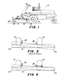
- FIG. 1 of the drawing shows a motor vehicle 10 in the form of a small tractor for lawn and garden maintenance. It is supported on a steerable rear wheel and two front driven drive wheels 12, which makes the small tractor very manoeuvrable and can be used particularly well with a mower mounted on the front.
- the mower housing or mower deck of the pushed front mower is designated 14, its left side 16 and its right side 18.
- Right and left front impellers 20 and 22 or pendulum wheels carry the front area 26 of the mower housing 14 with adjustable height.
- the front mower can be connected to the small tractor via a first and second or left and right push arm 28 and 30. For this purpose, they are connected to a front frame 24.
- Both push arms 28 and 30 have a front part 32, which is articulated on the mower housing 14, and a rear part 34, which is coupled to the motor vehicle 10.
- the rear parts 34 of the push arms 28 and 30 are connected to the motor vehicle 10 between its drive wheels 12 via ball joints 36 and 38, which enable a suspension that can be moved on all sides.
- the front parts 32 of the push arms 28 and 30 are connected to the mower housing 14 via ball joints 40 and 42. These enable the mower housing 14 to pivot about an axis running through both front ball joints 40 and 42.
- the two front ball joints 40 and 42 allow the mower to pivot about a horizontal or approximately horizontal axis running in the direction of travel if one side of the mower housing 14 or one of the pendulum wheels is guided over a raised area.
- Ball joints are used in the preferred embodiment, but other joints that allow movement in all directions can be used.
- the rear end of the mower housing 14 is suspended from the push arms 28 and 30 and only the left suspension is described in detail below.
- a boom 46 is fixedly arranged, which extends laterally outwards from the push arm 28.
- an angle lever 48 is pivotally attached, at the apex of which a rod 50 engages, which is connected at the other end to the front frame 24.
- the other leg of the angle lever 48 is connected to a side and rear area 54 of the mower housing 14 via a lost motion connection in the form of a link 52 having a longitudinal slot.
- the front end thereof can be adjusted in height by an operator and this setting is then automatically transferred to the rear area of the mower housing via the rod 50 and the angle lever 48. A separate setting in the area of the boom 46 is therefore unnecessary.
- the lost motion connection serves as a tipping point, as is indicated in FIG. 4.
- the right rear suspension of the mower housing 14 on the right thrust arm 30 can be done via a handlebar, which is similar to the handlebar 52.
- the preferred exemplary embodiment is also equipped with an oscillating rod 56 which is firmly connected to the left connecting rod 28 by means of screws 57. It has a stiffening 60 and a crank 58 and is connected at its other end to the right side of the motor vehicle 10.
- the right end of the swing rod 56 is inserted into the bore of the right rear ball joint 38 and can thus pivot independently of the right push rod 30.
- the rocking rod with the left push rod 28 moves up and down and around the connection with the right ball joint 38.
- the swing rod 56 prevents the left push rod 28 from tilting about its longitudinal axis as a result of the weight of the rear end of the rear end acting on it Mower.
- the boom 46 creates an additional moment in this area. Without such an oscillating rod 56, the left push arm 28 would tilt in its connection point with the left ball joint 36, since this allows movement in all directions. In addition, the weight of the rear area of the mower would then swing the boom 46 down. All of this is prevented by the swinging rod, and that with all others possible movements of the left push rod 28.
- the front mower By connecting the push rods 28 and 30 to the motor vehicle via right and left rear ball joints 36 and 38, the front mower can pivot vertically about a horizontal axis running through the ball joints 36 and 38. This makes it easy to overcome wide bumps before the motor vehicle hits them. The resulting cut is therefore much more uniform than in cases in which the front mower would be rigidly connected to the motor vehicle.
- the mower housing 14 can also tilt from one side to the other about axes running in the direction of travel and thus overcome one-sided elevations on the ground without one side being raised from the ground. If, for example, the right side of the front mower hits the ground with the right pendulum wheel 20 and the left pendulum wheel 22 does not, the right side of the mower will tilt upwards, pivoting around the left front ball joint 40. In the case of conventional mower housings, as shown in FIG. 3, their right outer edge 62 would be raised upwards, while their left side 62 would be pivoted further downwards.
- the push arms in conventional front mowers are connected relatively far to the rear of the motor vehicle and the rear ends of the mower housing, as far back as possible, to the rear ends of the push arms.
- the left rear portion 54 of the mower housing 14 is carried by the boom 46 and the left push arm 28.
- the weight of the mower tends to pull the left end of the boom 46 down and tilt the push arm 28 about its longitudinal axis.
- the left rear ball joint 36 does not counteract this tendency. If the swing rod 56 were not provided, the left push arm would then easily tilt in its connection point to the motor vehicle 10.
- the swing rod 56 prevents this, however, since it is fixedly connected at one end to the left push arm 28 and is pivotally connected at its other end to the motor vehicle 10 at a distance from the left push arm 28.
- the pivotable connection of the rocking rod 56 in the right rear ball joint 38 allows the rocking rod 56 to pivot with the left push arm 28 or to follow its movements.
Abstract
Vorrichtung zum Anschließen eines Frontmähers an ein Motorfahrzeug, insbesondere Kleinschlepper für die Rasen- und Gartenpflege, über mindestens einen Schubarm (28 bzw. 30), der mit seinem rückwärtigen Ende (34) vertikal schwenkbar an das Motorfahrzeug, mit seinem vorderen Ende (32) vertikal schwenkbar an das Mähergehäuse (14) des Frontmähers angeschlossen und mit einem sich nach seitlich außen erstreckenden Ausleger (46) fest verbunden ist, an dem das sich auf vorderen Laufrädern (20, 22) abstützende Mähergehäuse (14) in seinem seitlichen rückwärtigen Bereich (54) angeschlossen ist. <IMAGE>Device for connecting a front mower to a motor vehicle, in particular small tractors for lawn and garden maintenance, via at least one push arm (28 or 30), which with its rear end (34) can be pivoted vertically to the motor vehicle, with its front end (32) vertically pivotably connected to the mower housing (14) of the front mower and is fixedly connected to a laterally outwardly extending arm (46) on which the mower housing (14), which is supported on front wheels (20, 22), in its lateral rear area ( 54) is connected. <IMAGE>
Description
Die Erfindung bezieht sich auf eine Vorrichtung zum Anschließen eines Frontmähers an ein Motorfahrzeug, insbesondere Kleinschlepper für die Rasen- und Gartenpflege, über mindestens einen Schubarm, der mit seinem rückwärtigen Ende vertikal schwenkbar an das Motorfahrzeug und mit seinem vorderen Ende vertikal schwenkbar an das Mähergehäuse des Frontmähers angeschlossen ist.The invention relates to a device for connecting a front mower to a motor vehicle, in particular small tractors for lawn and garden maintenance, via at least one push arm, which can be pivoted vertically with its rear end to the motor vehicle and pivoted vertically with its front end to the mower housing Front mower is connected.
Kleinschlepper für die Garten- und Rasenpflege sind in der Regel so gebaut, daß zwischen ihren Achsen ein Mähwerk angeschlossen werden kann. Mit solchen Mähwerken läßt sich ein sauberer Rasenschnitt erzielen. Aber auch bei relativ großen Schnittbreiten, bei denen die Mähwerke seitlich über die Fahrzeugbreite hinausragen, entstehen Probleme mit schwer zugänglichen Stellen, an die das zwischen den Achsen angebaute Mähwerk nicht herankommt. Solche Stellen mußten dann von Hand nachgeschnitten werden. Ein Nachschneiden von Hand ist aber dann nicht mehr erforderlich, wenn der Mäher frontseitig an den Kleinschlepper angebaut ist. Ein solcher Anbau ermöglicht es, die sonst so schwer zugänglichen Stellen leichter zu erreichen. Große Flächenleistungen lassen sich insbesondere mit frontseitig angebauten Großflächenmähern erzielen, die drei nebeneinander angeordnete Sichelmesser aufweisen, sich durch eine flache Bauweise auszeichnen, um beispielsweise besser unter Sträuchern arbeiten zu können, und an dem Kleinschlepper seitlich versetzt angeschlossen sein können, damit in unterschiedlichen Spuren gefahren werden kann, um Bodenverdichtungen zu verhindern. Derartige Großflächenmäher sind an den Kleinschlepper pendelnd angebaut, damit der Mäher etwaigen Bodenunebenheiten folgen kann.Small tractors for garden and lawn care are usually built so that a mower can be connected between their axes. A clean lawn cut can be achieved with such mowers. But even with relatively large cutting widths, where the mowers protrude laterally beyond the width of the vehicle, problems arise with hard-to-reach places that the mower mounted between the axles cannot reach. Such places then had to be cut by hand. Trimming by hand is no longer necessary if the mower is attached to the front of the small tractor. Such an extension makes it easier to reach places that are otherwise difficult to access. Large area outputs can be achieved in particular with large mowers mounted on the front, which have three sickle knives arranged next to each other, are characterized by a flat design, for example to work better under bushes, and can be connected to the small tractor so that they are moved in different lanes can to prevent soil compaction. Such large area mowers are attached to the small tractor so that they can follow any bumps in the ground.
Bei der eingangs genannten Vorrichtung zum Anschließen eines Frontmähers an ein Motorfahrzeug (US-A-4 919 215) sind zwei Schubarme vorgesehen und die Aufhängung erfolgt über Kugelgelenke, damit der Frontmäher allseits beweglich ist und sich Bodenunebenheiten anpassen kann. Um ein seitliches Verkippen der Schubarme zu verhindern ist noch eine am Motorfahrzeug gelenkig gelagerte Schwingstange vorgesehen. Das rückwärtige Ende dieses Mähergehäuses ist nicht mit den Schubarmen verbunden. Eine solche Verbindung ist aber ebenfalls nicht mehr neu.In the above-mentioned device for connecting a front mower to a motor vehicle (US-A-4 919 215), two thrust arms are provided and the suspension is carried out via ball joints, so that the front mower can be moved on all sides and can adapt to uneven ground. In order to prevent the push arms from tilting sideways, an oscillating rod articulated on the motor vehicle is also provided. The rear end of this mower housing is not connected to the push arms. However, such a connection is also no longer new.
Es ist außerdem bekannt (US-A-4 760 686), einen Frontmäher derart auszubilden, daß er sich im Einsatz auf vorderen Laufrädern abstützt, wobei am rückwärtigen Ende des Mähergehäuses noch kleine Spurräder vorgesehen sind, die verhindern sollen, daß die Sichelmesser solcher Mähwerke in den Boden schneiden. Bei Arbeiten auf ebenem Grund haben diese Spurräder keinen Bodenkontakt, jedoch dann, wenn der Frontmäher bei Bodenunebenheiten ausreichend verkippt. Diese Spurräder erlauben dem Mähwerk eine Kippbewegung solange auszuführen, bis eins der Spurräder auf den Boden auftrifft, so daß dann das Gras in unterschiedlichen Höhen geschnitten wird, was unerwünscht ist, aber bei Kippbewegungen bei allen bisher bekannt gewordenen Frontmähern stets auftritt.It is also known (US-A-4 760 686) to design a front mower in such a way that it is supported in use on front wheels, with small track wheels being provided at the rear end of the mower housing, which should prevent the sickle blades of such mowers cut into the ground. When working on level ground, these track wheels have no contact with the ground, but when the front mower tilts sufficiently on uneven ground. These track wheels allow the mower to perform a tilting movement until one of the track wheels hits the ground, so that the grass is cut at different heights, which is undesirable, but always occurs with tilting movements in all previously known front mowers.
Die Erfindung will hier mit einer Vorrichtung Abhilfe schaffen, über die ein Mähergehäuse durch ein Motorfahrzeug derart geschoben werden kann, daß beim Auftreffen einer Seite des Mähergehäuses auf eine Bodenerhebung oder dergleichen, das korrespondierende Kippen der anderen Seite zumindest reduziert wird. Diese Aufgabe ist nach der Erfindung dadurch gelöst worden, daß der Schubarm mit einem sich nach seitlich außen erstrekkenden Ausleger fest verbunden ist, an dem das sich auf vorderen Laufrädern abstützende Mähergehäuse in seinem seitlichen rückwärtigen Bereich angeschlossen ist. Auf diese Weise ist die Kippachse seitlich verlegt worden, so daß, wenn beispielsweise das dem Ausleger abgelegene vordere Laufrad auf eine Bodenerhöhung trifft, die dem Ausleger zugelegene kurze Seite des Mähergehäuses nach unten kippt. Da aber das Mähergehäuse um die nunmehr seitlich verlegte und rückwärtige Verbindung des Frontmähers mit dem Ausleger kippt, ist der Kippbereich geringer als bei den bisher bekannt gewordenen frontseitig angebauten Mähern, wodurch letztlich ein gleichmäßiger Schnitt erreicht wird.The invention seeks to remedy this with a device via which a mower housing can be pushed by a motor vehicle in such a way that when one side of the mower housing strikes a ground elevation or the like, the corresponding tilting of the other side is at least reduced. This object has been achieved according to the invention in that the thrust arm is fixedly connected to a laterally outwardly extending boom, to which the mower housing, which is supported on front wheels, is connected in its lateral rear region. In this way, the tilt axis has been moved laterally, so that if, for example, the front impeller remote from the boom hits a raised area, the short side of the mower housing facing the boom tilts downward. However, since the mower housing tilts around the now laterally laid and rear connection of the front mower to the boom, the tipping range is smaller than with the mowers mounted on the front, which have become known so far, which ultimately achieves a uniform cut.
Bei einer Vorrichtung, bei der der Schubarm mit dem Mähergehäuse und dem Motorfahrzeug allseits beweglich verbunden und eine Schwingstange einenends schwenkbar an das Motorfahrzeug und anderenends fest an den Schubarm angeschlossen ist, wird nach der Erfindung ferner vorgeschlagen, daß an den Ausleger ein Winkelhebel angeschlossen ist, der an dem seitlichen rückwärtigen Bereich des Mähergehäuses über eine Totgangverbindung angreift.In a device in which the push arm is movably connected to the mower housing and the motor vehicle on all sides and a rocking rod is pivotally connected at one end to the motor vehicle and at the other end firmly to the push arm, it is further proposed according to the invention that an angle lever is connected to the boom, which engages the rear side area of the mower housing via a lost motion connection.
Zweckmäßig kann außerdem der Winkelhebel schwenkbar an dem Ausleger angeschlossen und über eine Stange mit einem Frontteil des Mähergehäuses verbunden sein. Hierdurch wird das rückwärtige Ende des Mähers automatisch mitverstellt, wenn über gesonderte und an sich bekannte Mittel das vordere Ende des Frontmähers höhenverstellt wird.Advantageously, the angle lever can also be pivotally connected to the boom and connected to a front part of the mower housing via a rod. As a result, the rear end of the mower is automatically adjusted when the front end of the front mower is adjusted in height using separate and known means.
Damit insbesondere keine Bodenverdichtungen durch ständiges Fahren in der gleichen Spur auftreten, wird nach der Erfindung ferner noch vorgeschlagen, daß der Frontmäher seitlich versetzt an das Motorfahrzeug angeschlossen ist und sich der Ausleger von dem Schubarm aus gesehen in die Richtung erstreckt, in die der Frontmäher weiter nach außen versetzt ist.So that in particular no soil compaction occurs due to constant driving in the same lane, it is further proposed according to the invention that the front mower is connected laterally offset to the motor vehicle and the boom extends from the push arm in the direction in which the front mower continues is shifted to the outside.
In den Fig. 1, 2 und 4 der Zeichnung ist ein nachfolgend näher erläutertes Ausführungsbeispiel der Erfindung dargestellt. Es zeigt:
- Fig. 1 einen Kleinschlepper mit angeschlossenem großflächigen Frontmäher,
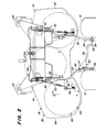
- Fig. 2 eine Anschlußvorrichtung des Frontmähers an den Kleinschlepper in Draufsicht,
- Fig. 3 den möglichen Kippbereich eines herkömmlichen Frontmähers,
- Fig. 4 den reduzierten Kippbereich des Frontmähers nach der Erfindung und
- Fig. 5 die Verbindung des seitlichen rückwärtigen Endes des Mähergehäuses mit einem Schubarm.
- 1 shows a small tractor with a large front mower connected,
- 2 is a top view of a connection device of the front mower to the small tractor,
- 3 shows the possible tilting range of a conventional front mower,
- Fig. 4 shows the reduced tilt range of the front mower according to the invention and
- Fig. 5 shows the connection of the rear side end of the mower housing with a push arm.
Die in der nachfolgenden Beschreibung verwendeten Begriffe rechts und links beziehen sich auf die Blickrichtung einer hinter dem Kleinschlepper sich befindlichen Person.The terms used on the right and left in the following description refer to the direction of view of a person behind the small tractor.
In Fig. 1 der Zeichnung ist ein Motorfahrzeug 10 in Form eines Kleinschleppers für die Rasen-und Gartenpflege dargestellt. Es stützt sich auf einem lenkbaren rückwärtigen Laufrad und zwei vorderen angetriebenen Treibrädern 12 ab, wodurch der Kleinschlepper sehr wendig ist und besonders gut mit einem frontseitig angebauten Mäher eingesetzt werden kann. Das Mähergehäuse oder Mäherdeck des geschobenen Frontmähers ist mit 14, seine linke Seite mit 16 und seine rechte Seite mit 18 bezeichnet. Rechte und linke vordere Laufräder 20 und 22 bzw. Pendelräder tragen den frontseitigen Bereich 26 des Mähergehäuses 14 höheneinstellbar. Der Frontmäher ist über einen ersten und zweiten oder linken und rechten Schubarm 28 und 30 an den Kleinschlepper anschließbar. Sie sind hierzu an einen Frontrahmen 24 angeschlossen. Beide Schubarme 28 und 30 weisen einen vorderen Teil 32, der an dem Mähergehäuse 14 angelenkt ist, und einen rückwärtigen Teil 34 auf, der mit dem Motorfahrzeug 10 gekuppelt ist. Hierbei erfolgt die Verbindung der rückwärtigen Teile 34 der Schubarme 28 und 30 mit dem Motorfahrzeug 10 zwischen dessen Treibrädern 12 über Kugelgelenke 36 und 38, die eine allseits bewegliche Aufhängung ermöglichen. Desgleichen erfolgt die Verbindung der vorderen Teile 32 der Schubarme 28 und 30 mit dem Mähergehäuse 14 über Kugelgelenke 40 und 42. Diese ermöglichen dem Mähergehäuse 14 eine Schwenkbewegung um eine durch beide vorderen Kugelgelenke 40 und 42 verlaufende Achse. Gleichfalls erlauben die beiden vorderen Kugelgelenke 40 und 42 dem Mäher eine Schwenkbewegung um eine in Fahrtrichtung verlaufende horizontale oder etwa horizontale Achse, wenn eine Seite des Mähergehäuses 14 bzw. eins der Pendelräder über eine Bodenerhebung geführt wird. Beim bevorzugten Ausführungsbeispiel sind Kugelgelenke eingesetzt, doch können auch andere Gelenke, die eine Bewegung in allen Richtungen zulassen, Verwendung finden.1 of the drawing shows a
Das rückwärtige Ende des Mähergehäuses 14 ist an den Schubarmen 28 und 30 aufgehängt und nur die linke Aufhängung wird im einzelnen nachfolgend beschrieben. An dem linken Schubarm 28 ist, wie aus den Fig. 2 und 5 ersichtlich ist, ein Ausleger 46 fest angeordnet, der sich von dem Schubarm 28 seitlich nach außen erstreckt. An seinem freien Ende ist ein Winkelhebel 48 verschwenkbar angebracht, in dessen Scheitelpunkt etwa eine Stange 50 angreift, die anderenends mit dem Frontrahmen 24 verbunden ist. Der andere Schenkel des Winkelhebels 48 ist über eine Totgangverbindung in Form eines einen Längsschlitz aufweisenden Lenkers 52 an einen seitlichen und rückwärtigen Bereich 54 des Mähergehäuses 14 angeschlossen. Bei derartigen Mähern kann deren frontseitiges Ende von einer Bedienungsperson höheneingestellt werden und diese Einstellung wird dann automatisch über die Stange 50 und den Winkelhebel 48 auf den rückwärtigen Bereich des Mähergehäuses übertragen. Eine gesonderte Einstellung im Bereich des Auslegers 46 ist damit überflüssig. Beim Überfahren von Bodenunebenheiten dient die Totgangverbindung als Kippunkt, wie dies in der Fig. 4 angedeutet ist.The rear end of the
Die rechte rückwärtige Aufhängung des Mähergehäuses 14 an den rechten Schubarm 30 kann über einen Lenker erfolgen, der ähnlich dem Lenker 52 ausgebildet ist.The right rear suspension of the
Das bevorzugte Ausführungsbeispiel ist, wie ebenfalls aus Fig. 2 erkennbar ist, noch mit einer Schwingstange 56 ausgerüstet, die über Schrauben 57 an die linke Schubstange 28 fest angeschlossen ist. Sie weist eine Versteifung 60 und eine Kröpfung 58 auf und ist mit ihrem anderen Ende mit der rechten Seite des Motorfahrzeugs 10 verbunden. Beim Ausführungsbeispiel ist das rechte Ende der Schwingstange 56 in die Bohrung des rechten rückwärtigen Kugelgelenkes 38 eingesetzt und kann damit unabhängig von der rechten Schubstange 30 verschwenken. Infolge der festen Verbindung bewegt sich die Schwingstange mit der linken Schubstange 28 auf und ab und um die Verbindung mit dem rechten Kugelgelenk 38. Die Schwingstange 56 verhindert, daß die linke Schubstange 28 um ihre Längsachse verkippt infolge des auf sie einwirkenden Gewichtes des rückwärtigen Endes des Mähers. Durch den Ausleger 46 entsteht in diesem Bereich noch ein zusätzliches Moment. Ohne eine solche Schwingstange 56 würde der linke Schubarm 28 in seiner Anschlußstelle mit dem linken Kugelgelenk 36 verkippen, da dieses eine Bewegung in alle Richtungen zuläßt. Außerdem würde dann das Gewicht des rückwärtigen Bereiches des Mähers den Ausleger 46 nach unten schwenken. Alles dies wird durch die Schwingstange verhindert, und zwar bei sämtlichen anderen möglichen Bewegungen der linken Schubstange 28.The preferred exemplary embodiment, as can also be seen from FIG. 2, is also equipped with an
Im nachfolgenden wird auf die Wirkungsweise der vorstehend beschriebenen Vorrichtung eingegangen. Durch den Anschluß der Schubstangen 28 und 30 an das Motorfahrzeug über rechte und linke rückwärtige Kugelgelenke 36 und 38 kann der Frontmäher um eine durch die Kugelgelenke 36 und 38 verlaufende horizontale Achse vertikal verschwenken. Damit können breite Bodenwellen leicht überwunden werden, und zwar bevor das Motorfahrzeug auf diese trifft. Der daraus resultierende Schnitt ist damit wesentlich gleichmäßiger als in solchen Fällen, in denen der Frontmäher starr mit dem Motorfahrzeug verbunden wäre.The mode of operation of the device described above is discussed below. By connecting the
Das Mähergehäuse 14 kann außerdem um in Fahrtrichtung verlaufende Achsen von einer Seite auf die andere kippen und so einseitige Bodenerhebungen überwinden, ohne daß sich eine Seite von dem Boden abheben würde. Trifft beispielsweise die rechte Seite des Frontmähers mit dem rechten Pendelrad 20 auf eine Bodenerhebung und das linke Pendelrad 22 jedoch nicht, dann wird die rechte Seite des Mähers nach oben kippen, wobei die Verschwenkung um das linke vordere Kugelgelenk 40 erfolgt. Bei herkömmlichen Mähergehäusen, wie sie in der Fig. 3 dargestellt sind, würde dabei deren rechte Außenkante 62 nach oben angehoben, während deren linke Seite 62 weiter nach unten verschwenkt würde. Aus Stabilitätsgründen sind die Schubarme bei herkömmlichen Frontmähern relativ weit hinten am Motorfahrzeug angeschlossen und die rückwärtigen Enden der Mähergehäuse, ebenso weit hinten wie möglich, an den rückwärtigen Enden der Schubarme. Das Kippen erfolgt um einen dieser Anschlüsse und insbesondere bei Großflächenmähern ist dann der von diesem Anschluß noch seitlich weisende Teil recht lang, so daß sich dieser Teil recht tief absenken kann und gegebenenfalls mit dem Boden Kontakt bekommt. Verstärkt wird dies noch dann auftreten, wenn das Großflächenmähwerk versetzt angeordnet ist, wenn sich also ein äußeres Sichelmesser vor einem Treibrad befindet und das andere äußere Sichelmesser seitlich außen neben dem anderen Treibrad. Bei all diesen herkömmlichen Kippbewegungen tritt zumindest ein ungleichmäßiger Schnitt auf, und ein Aufschlagen des außen und unten liegenden Sichelmessers auf die Grasnabe ist häufig die Folge.The
Bei der Vorrichtung nach der vorliegenden Erfindung treten diese Nachteile nicht auf oder werden zumindest reduziert. Trifft zum Beispiel bei einem mit der erfindungsgemäßen Vorrichtung ausgerüsteten Mäher die rechte Seite 18 auf eine Bodenerhebung, wie es schematisch in Fig.4 dargestellt ist, dann schwenkt zunächst der rechte Schubarm 30 nach oben um seine Anschlußstelle im rechten rückwärtigen Kugelgelenk 38. Da der linke Teil des Mähers nicht über eine Bodenerhebung fährt, wird auch der linke Schubarm 28 nicht bei diesem Vorgang höhenverschwenkt. Das Mähergehäuse 14 wird daher um seine Anschlußstelle an den Ausleger 46 nach einer Seite kippen, wobei die rechte Seite angehoben wird und die Bodenerhebung überwindet. Gleichzeitig kippt die linke Seite 64 des Mähergehäuses ein wenig nach unten. Die nach unten gerichtete Kippbewegung ist reduziert, da der Schwenkpunkt infolge des nach seitlich außen weisenden Auslegers 46 seitlich nach außen verlegt worden ist.In the device according to the present invention, these disadvantages do not occur or are at least reduced. If, for example, the
Während des Einsatzes wird der linke rückwärtige Bereich 54 des Mähergehäuses 14 von dem Ausleger 46 und dem linken Schubarm 28 getragen. Das Gewicht des Mähers tendiert dazu, das linke Ende des Auslegers 46 nach unten zu ziehen und den Schubarm 28 um seine Längsachse zu verkippen. Dieser Tendenz wirkt das linke rückwärtige Kugelgelenk 36 nicht entgegen. Wäre die Schwingstange 56 nicht vorgesehen, so würde dann der linke Schubarm ohne weiteres in seiner Anschlußstelle an das Motorfahrzeug 10 verkippen. Die Schwingstange 56 aber verhindert dies, da sie mit ihrem einem Ende mit dem linken Schubarm 28 fest verbunden ist und mit ihrem anderen Ende mit Abstand zu dem linken Schubarm 28 am Motorfahrzeug 10 schwenkbar angeschlossen ist. Der schwenkbare Anschluß der Schwingstange 56 in dem rechten rückwärtigen Kugelgelenk 38 erlaubt es, daß die Schwingstange 56 mit dem linken Schubarm 28 verschwenkt bzw. dessen Bewegungen folgt.During operation, the left
Claims (4)
Applications Claiming Priority (2)
| Application Number | Priority Date | Filing Date | Title |
|---|---|---|---|
| US555971 | 1983-11-29 | ||
| US07/555,971 US5029437A (en) | 1990-07-19 | 1990-07-19 | Mower deck outrigger suspension |
Publications (2)
| Publication Number | Publication Date |
|---|---|
| EP0469351A1 true EP0469351A1 (en) | 1992-02-05 |
| EP0469351B1 EP0469351B1 (en) | 1993-12-22 |
Family
ID=24219369
Family Applications (1)
| Application Number | Title | Priority Date | Filing Date |
|---|---|---|---|
| EP91111464A Expired - Lifetime EP0469351B1 (en) | 1990-07-19 | 1991-07-10 | Device for attaching a front mounted mower to a motor vehicle |
Country Status (4)
| Country | Link |
|---|---|
| US (1) | US5029437A (en) |
| EP (1) | EP0469351B1 (en) |
| CA (1) | CA2045378C (en) |
| DE (1) | DE59100748D1 (en) |
Families Citing this family (4)
| Publication number | Priority date | Publication date | Assignee | Title |
|---|---|---|---|---|
| US5425224A (en) * | 1994-08-08 | 1995-06-20 | Downey; Sam | Mower deck carriage |
| US5813203A (en) * | 1996-07-12 | 1998-09-29 | Mtd Products Inc. | Lost motion lift control for a mower deck |
| JP3474103B2 (en) * | 1998-05-26 | 2003-12-08 | 株式会社クボタ | Mower suspension equipment for lawn mowers |
| EP3106014B1 (en) | 2015-06-19 | 2018-05-09 | Stiga S.p.A. in breve anche St. S.p.A. | Lift apparatus of a lawn mower cutting deck |
Citations (9)
| Publication number | Priority date | Publication date | Assignee | Title |
|---|---|---|---|---|
| US3702051A (en) * | 1970-09-08 | 1972-11-07 | John Deines | Independently operable dual drive wheel riding power mower |
| US4313295A (en) * | 1980-02-11 | 1982-02-02 | Outboard Marine Corporation | Blade housing mount for riding mowers |
| US4320616A (en) * | 1980-12-18 | 1982-03-23 | J. I. Case Company | Lawn mower suspension |
| US4325211A (en) * | 1980-09-02 | 1982-04-20 | The Toro Company | Floating deck for rider mower |
| EP0245824A1 (en) * | 1986-05-13 | 1987-11-19 | Deere & Company | Device for adjusting a mowing appliance |
| FR2608006A1 (en) * | 1986-12-16 | 1988-06-17 | Kubota Ltd | MOWER FIXED IN THE FRONT OF A VEHICLE |
| US4760686A (en) * | 1986-02-04 | 1988-08-02 | Kubota Ltd. | Attachment device for front-mountable working implement |
| US4869057A (en) * | 1987-05-26 | 1989-09-26 | Mtd Products Inc. | Mower deck height and angle control |
| US4919215A (en) * | 1989-03-22 | 1990-04-24 | Deere & Company | Hitch with anti-sway link |
Family Cites Families (1)
| Publication number | Priority date | Publication date | Assignee | Title |
|---|---|---|---|---|
| US3402536A (en) * | 1967-08-10 | 1968-09-24 | Slope Tractor Inc | Slope mower vehicle |
-
1990
- 1990-07-19 US US07/555,971 patent/US5029437A/en not_active Expired - Lifetime
-
1991
- 1991-06-25 CA CA002045378A patent/CA2045378C/en not_active Expired - Fee Related
- 1991-07-10 EP EP91111464A patent/EP0469351B1/en not_active Expired - Lifetime
- 1991-07-10 DE DE91111464T patent/DE59100748D1/en not_active Expired - Fee Related
Patent Citations (10)
| Publication number | Priority date | Publication date | Assignee | Title |
|---|---|---|---|---|
| US3702051A (en) * | 1970-09-08 | 1972-11-07 | John Deines | Independently operable dual drive wheel riding power mower |
| US4313295A (en) * | 1980-02-11 | 1982-02-02 | Outboard Marine Corporation | Blade housing mount for riding mowers |
| US4325211A (en) * | 1980-09-02 | 1982-04-20 | The Toro Company | Floating deck for rider mower |
| US4325211B1 (en) * | 1980-09-02 | 1988-11-29 | ||
| US4320616A (en) * | 1980-12-18 | 1982-03-23 | J. I. Case Company | Lawn mower suspension |
| US4760686A (en) * | 1986-02-04 | 1988-08-02 | Kubota Ltd. | Attachment device for front-mountable working implement |
| EP0245824A1 (en) * | 1986-05-13 | 1987-11-19 | Deere & Company | Device for adjusting a mowing appliance |
| FR2608006A1 (en) * | 1986-12-16 | 1988-06-17 | Kubota Ltd | MOWER FIXED IN THE FRONT OF A VEHICLE |
| US4869057A (en) * | 1987-05-26 | 1989-09-26 | Mtd Products Inc. | Mower deck height and angle control |
| US4919215A (en) * | 1989-03-22 | 1990-04-24 | Deere & Company | Hitch with anti-sway link |
Also Published As
| Publication number | Publication date |
|---|---|
| CA2045378A1 (en) | 1992-01-20 |
| EP0469351B1 (en) | 1993-12-22 |
| US5029437A (en) | 1991-07-09 |
| DE59100748D1 (en) | 1994-02-03 |
| CA2045378C (en) | 1993-05-11 |
Similar Documents
| Publication | Publication Date | Title |
|---|---|---|
| EP0475021B1 (en) | Mower, especially front-mounted mower | |
| EP0523578B1 (en) | Four wheel steering for a vehicle | |
| DE2743109A1 (en) | PLOW | |
| DE3022742A1 (en) | BASE FOR AGRICULTURAL MACHINERY | |
| DE919613C (en) | Maher attachment to tugs | |
| DE69824790T2 (en) | Machine with a pivotable relative to the support structure machining unit and pivoting method | |
| DE3343005A1 (en) | TOW ROD FOR MOUNTING TOOL MOUNTING APPLICABLE TO THE GROUND CONTOUR | |
| DE2053073B2 (en) | mower | |
| EP1106051A1 (en) | Mower | |
| EP0933013A1 (en) | Adjusting mechanism and cutting unit | |
| EP0807377A2 (en) | Device for connecting a height adjustable implement to a vehicle from a working in a transport position | |
| DE19818960A1 (en) | Wheel suspension for agricultural machine | |
| DE69909378T2 (en) | SELF-DRIVING MOWER | |
| DE2164650A1 (en) | LAWN MOWER, IN PARTICULAR LAWN MOWER WITH SEAT ARRANGEMENT | |
| EP1266551B1 (en) | Working machine for mounting on a vehicle | |
| EP0388801A2 (en) | Hydraulic lifting device | |
| EP0469351B1 (en) | Device for attaching a front mounted mower to a motor vehicle | |
| DE1482095C3 (en) | mower | |
| DE3530107C2 (en) | plow | |
| DE60224766T2 (en) | Support frame for mower | |
| DE3835367C5 (en) | Device for mowers for ground adaptation of the cutting units | |
| DE19618839B4 (en) | Doppelkreiselschwader | |
| DE2607364B2 (en) | DEVICE FOR DEEP LOOSENING OF SOILS | |
| EP0427149B1 (en) | Device for connecting an agricultural machine to a three-point linkage | |
| DE19604758A1 (en) | Rotor with wire loops for pruning fruit trees |
Legal Events
| Date | Code | Title | Description |
|---|---|---|---|
| PUAI | Public reference made under article 153(3) epc to a published international application that has entered the european phase |
Free format text: ORIGINAL CODE: 0009012 |
|
| AK | Designated contracting states |
Kind code of ref document: A1 Designated state(s): DE FR GB IT |
|
| 17P | Request for examination filed |
Effective date: 19920116 |
|
| 17Q | First examination report despatched |
Effective date: 19921217 |
|
| GRAA | (expected) grant |
Free format text: ORIGINAL CODE: 0009210 |
|
| AK | Designated contracting states |
Kind code of ref document: B1 Designated state(s): DE FR GB IT |
|
| GBT | Gb: translation of ep patent filed (gb section 77(6)(a)/1977) |
Effective date: 19940105 |
|
| REF | Corresponds to: |
Ref document number: 59100748 Country of ref document: DE Date of ref document: 19940203 |
|
| ITF | It: translation for a ep patent filed |
Owner name: LENZI & C. |
|
| ET | Fr: translation filed | ||
| PLBE | No opposition filed within time limit |
Free format text: ORIGINAL CODE: 0009261 |
|
| STAA | Information on the status of an ep patent application or granted ep patent |
Free format text: STATUS: NO OPPOSITION FILED WITHIN TIME LIMIT |
|
| 26N | No opposition filed | ||
| REG | Reference to a national code |
Ref country code: GB Ref legal event code: IF02 |
|
| PGFP | Annual fee paid to national office [announced via postgrant information from national office to epo] |
Ref country code: DE Payment date: 20060620 Year of fee payment: 16 |
|
| PGFP | Annual fee paid to national office [announced via postgrant information from national office to epo] |
Ref country code: IT Payment date: 20060731 Year of fee payment: 16 |
|
| PG25 | Lapsed in a contracting state [announced via postgrant information from national office to epo] |
Ref country code: DE Free format text: LAPSE BECAUSE OF NON-PAYMENT OF DUE FEES Effective date: 20080201 |
|
| PGFP | Annual fee paid to national office [announced via postgrant information from national office to epo] |
Ref country code: FR Payment date: 20070717 Year of fee payment: 17 |
|
| REG | Reference to a national code |
Ref country code: FR Ref legal event code: ST Effective date: 20090331 |
|
| PG25 | Lapsed in a contracting state [announced via postgrant information from national office to epo] |
Ref country code: FR Free format text: LAPSE BECAUSE OF NON-PAYMENT OF DUE FEES Effective date: 20080731 |
|
| PG25 | Lapsed in a contracting state [announced via postgrant information from national office to epo] |
Ref country code: IT Free format text: LAPSE BECAUSE OF NON-PAYMENT OF DUE FEES Effective date: 20070710 |
|
| PGFP | Annual fee paid to national office [announced via postgrant information from national office to epo] |
Ref country code: GB Payment date: 20090727 Year of fee payment: 19 |
|
| GBPC | Gb: european patent ceased through non-payment of renewal fee |
Effective date: 20100710 |
|
| PG25 | Lapsed in a contracting state [announced via postgrant information from national office to epo] |
Ref country code: GB Free format text: LAPSE BECAUSE OF NON-PAYMENT OF DUE FEES Effective date: 20100710 |