EP0545676A1 - An ergonomic control system for swing reach vehicles - Google Patents
An ergonomic control system for swing reach vehicles Download PDFInfo
- Publication number
- EP0545676A1 EP0545676A1 EP92310984A EP92310984A EP0545676A1 EP 0545676 A1 EP0545676 A1 EP 0545676A1 EP 92310984 A EP92310984 A EP 92310984A EP 92310984 A EP92310984 A EP 92310984A EP 0545676 A1 EP0545676 A1 EP 0545676A1
- Authority
- EP
- European Patent Office
- Prior art keywords
- control
- operator
- vehicle
- handles
- control system
- Prior art date
- Legal status (The legal status is an assumption and is not a legal conclusion. Google has not performed a legal analysis and makes no representation as to the accuracy of the status listed.)
- Withdrawn
Links
Images


Classifications
-
- B—PERFORMING OPERATIONS; TRANSPORTING
- B66—HOISTING; LIFTING; HAULING
- B66F—HOISTING, LIFTING, HAULING OR PUSHING, NOT OTHERWISE PROVIDED FOR, e.g. DEVICES WHICH APPLY A LIFTING OR PUSHING FORCE DIRECTLY TO THE SURFACE OF A LOAD
- B66F9/00—Devices for lifting or lowering bulky or heavy goods for loading or unloading purposes
- B66F9/06—Devices for lifting or lowering bulky or heavy goods for loading or unloading purposes movable, with their loads, on wheels or the like, e.g. fork-lift trucks
- B66F9/075—Constructional features or details
- B66F9/20—Means for actuating or controlling masts, platforms, or forks
Definitions
- the invention relates to an advanced control system for material handling vehicles containing new and improved control features for combining ease of operation with safety, and more particularly to an ergonometric set of controls for operating fork lift vehicles with greater comfort, ease, efficiency and safety.
- control levers are contrary to the normal senses of the operator relative to the motions of the operation.
- fork movement levers may require a push or a pull to lift or lower the lifting mechanism.
- the same lever may be used to actuate several functions via a secondary select switch.
- Such actuating devices can cause confusion and inefficiency.
- Motions contrary to the normal senses not only make the task of learning to operate the material handling vehicle more difficult, but may also be an underlying cause of confusion leading to improper operation.
- the present invention seeks to overcome all of the above drawbacks and disadvantages.
- the current invention seeks to reduce expended energies and motions by operators of fork lift vehicles in actuating the vehicular controls. These measurements have resulted in a new control ergonometry. Switching or selecting control functions has been designed to be more electrically and less mechanically actuatable.
- a new pair of control levers or handles has been designed.
- the new handles are shaped to conform to the grip of the human hand, thus providing operator comfort.
- Most of the control function actuators have been designed and integrated into these control handles, reducing the time and energy needed to reach, push or pull these actuator controls.
- Most of the controls are at the finger tips of the operator providing easy access. Simultaneous functions can be accomplished easily.
- Each of the finger tip controls has a different shape, feel, and/or actuation movement, so that each control actuator is easily distinguished from its neighboring control actuators.
- Each function is easily selected, thus eliminating confusion, and allowing the operator to easily learn to operate the vehicle. This ease of operation translates into operating efficiency.
- actuators require a minimum of motion and/or energy to access and operate. This additionally translates into operating efficiency.
- the actuators have been designed to provide tactile awareness. They conform to the natural, intuitive motions and senses of the operator, and to the functions that are being actuated. This translates into operating safety.
- the ergonometric control system of this invention therefore provides controls that the operator will find comfortable, easy to operate, efficient and safe.
- an ergonometric control system for material handling vehicles, such as fork lift trucks.
- the system comprises a pair of right and left control handles.
- the handles are disposed about the operator compartment of the vehicle, and are utilized to control the vehicle.
- the handles conform to the respective right and left hand grips of the operator.
- the handles provide operator support throughout vehicle operation. As such, this conformity to the hand grips provides comfortable controls as well as ease of vehicle operation.
- Each handle comprises a plurality of closely spaced, easily accessed function actuators that allow for simultaneous control of two or more vehicular functions. All the actuators are integrated into their respective handle, such that they are within finger tip reach of the operator's hand.
- These actuators and handles each provide intuitive sense control. That is, each handle and actuator moves in the same sense as the function for which it is designed. For example, when seated or standing while facing the forks, the right handle is thrust forward for forks first movement and backward for tractor first movement of the fork lift vehicle.
- a lift/lower lever actuator on the top portion of the right handle is positioned off-center, so that the operator pushes upward or downward on this lever to effectuate the respective lifting and lowering of the main mast or auxiliary mast.
- a horn push button is disposed adjacent the lift/lower lever on the right handle. Below the horn button is disposed a two-position, toggle-type, automatic/manual select switch for selecting manual steering or automatic (guide wire) control of the vehicle. Still another push button disposed adjacent the automatic/manual select switch coordinates vehicle rotation and travel functions.
- a fork rotate lever On the top portion of the left handle is located a fork rotate lever disposed off-center. This fork rotate lever is pushed either to the right (CW) or left (CCW) for actuating the rotation of the forks either clockwise (CW) or counterclockwise (CCW), respectively.
- a push button for selecting the auxiliary mast over the main mast. Actuating the lift/lower lever causes the main mast to lift or lower, and actuating the lift/lower lever while depressing the mast select push button causes the auxiliary mast to lift or lower.
- Adjacent the mast select push button is an optional three-position toggle-type selector switch for tilting the forks. Next to this switch is a push button for overriding the mast vertical travel limit.
- the left control handle itself can be thrust forward and backward to provide movement of the auxiliary mast and forks to the left and to the right, respectively.
- actuators are physically and functionally distinct in how they are accessed, so that they do not cause confusion between the particular functions being controlled. This in turn makes the control system easier to learn and to operate.
- the invention features a new ergonometric control system for a material handling vehicle, such as a fork lift truck.
- the control system of the invention is user friendly.
- the controls have been designed to be comfortable to the vehicle operator, provide easier access to the function actuators, and allow for- simultaneous control of two or more vehicle functions.
- FIGURE 1 a swing-reach truck 10 is shown, with an operator 9 sitting at the ergonometric controls of this invention.
- the ergonometric controls are part of an operator compartment described in greater detail hereinbelow.
- the swing-reach truck 10 is a typical type of material handling vehicle that can benefit from the ergonometric control system of this invention. It is to be understood that this vehicle is one of many vehicles that can utilize the invention, and is displayed herein by way of example.
- the swing-reach truck 10 comprises a pair of forks 12 that are carried upon a rotatable frame 13 so that the forks 12 can rotate 180° from facing left with respect to the seated operator 9 (as shown) to facing right.
- the rotatable frame 13 is rotatively connected to extension arm 14 via a rotating shaft 15.
- Extension arm 14 is vertically movable upon an auxiliary mast 16 via a chain 19, which is carried by a hydraulic cylinder 19a.
- the forks 12 are movable up and down (arrow 20).
- Auxiliary mast 16 is horizontally movable along upper and lower racks 25 and 26, respectively. In this way, the mast/fork assembly can be transported from the seated operator's right (as shown) to his left.
- forks 12 are extendable from rotatable frame 13 on a scissor-like mechanism (not shown). This extending action occurs automatically at the end of the horizontal movement of mast 16 along racks 26 and 26, thus bridging the gap between vehicle 10 and storage racks, not shown.
- the operator platform 18, carrying the operator 9 and auxiliary mast assembly 16, is likewise movable up and down (arrows 22) via a main mast 21 via chains, not shown, which are carried by hydraulic cylinders, not shown.
- control arms 24 and 25 each carry respective right and left control handles 30 and 31.
- Control arm 25 also carries a vehicle steering knob 29, and control arm 24 also carries an emergency power off (EPO) palm depress button 26.
- EPO emergency power off
- control console 27 which includes a power key switch 27a, an operator display 27b and a plurality of selector switches 27c for work lights and fans.
- control handles 30 and 31 are shown in an operating position facing towards the forks. It will be noted that the right control handle 30 is a mirror image of the control handle 31. However, each control arm, with its respective actuators described hereinbelow, controls different functions.
- the control handles 30 and 31 are shaped to conform to the grip of the operator 9.
- the respective contoured surfaces 40 and 41 conform to the clenched hands of the operator, and provide a comfortable grasp of the control handles 30 and 31, respectively. This is important, because these handles can serve to support the operator 9 during the operation and movement of the vehicle.
- Control handle 30 controls the vehicle travel direction and speed when it is rotationally displaced about axis 35.
- Control handle 31 controls the horizontal displacement and speed of auxiliary mast 16 along racks 25 and 26, including the extension of the scissor-like mechanism, not shown. Pushing control handle 31 moves auxiliary mast 16 to the left, while pulling handle 31 moves mast 16 to the right.
- the right control handle 30 has a number of distinctive actuators A, B, C and D, which correspond to the actuators A', B', C' and D' disposed on control handle 31. It will also be observed that each of the respective actuators A, B, C, and D, or A', B', C' and D' on the right or the left control arms 30 and 31, respectively, has a different shape, and actuates a control function in a different way.
- actuator levers D and D' each are disposed at the top portions 50 of the control arms. They are located in off-center locations on top portions 50, necessitating that the thumb of the hand must push upwardly or downwardly (arrows 45 and 46) upon these levers to effectuate lever movement.
- Lever D controls the lifting or lowering speed of the forks 12 upon main mast 21, while lever D' controls the rotation direction and speed of the forks with respect to support arm 14.
- buttons A and A' control the vehicle horn and the lift/lower selection of the auxiliary mast 16 respectively, in the lift mode.
- button A' is held depressed while lever D is rotated in order to raise or lower the auxiliary mast 16. If lever D is rotated without depressing button A', the main mast 21 is controlled.
- These buttons must be depressed by the thumb, rather than pushed or pulled, as required for levers D and D', in order to actuate their functions.
- Selector switches B and B' respectively control the manual/automatic vehicle travel mode and the fork tilting positions.
- the manual/automatic vehicle travel mode relates to either driver operated or guided vehicular control.
- the three-position spring return-to-center selector switch B' allows the forks 12 to tilt upwardly or downwardly.
- Selector switch B is a two-position rocker switch, and requires a rocking motion to effect actuation of the desired function. These switches B and B' can generally be actuated by the middle fingers or thumb of the operator's hand.
- round cap button C in conjunction with left control handle 31, selects the coordination between rotation of forks 12 and horizontal traverse of auxiliary mast 16 along racks 25 and 26 in accordance with a preprogrammed speed/displacement profile.
- Round cap button C' is used, when lifting, to override the main mast lift/limit switch, not shown. These round cap buttons C and C' can be depressed by the operator's thumb in order to actuate their functions.
- each switch, button, lever, etc. including the control handles, is designed to move in a direction that is conceived to be functionally proper by the operator. This tactile awareness also assists in actuating the various functions properly, and avoids costly errors.
- the present invention by placing all the control functions within finger-tip control, not only eliminates the previous need to move between control levers, but also eliminates large throw distances for actuation. All of the advantages of the invention provide a reduction in energy and effort. At the end of the work shift, the operator will be less tired and fatigued. Also, as aforementioned, the control handles 30 and 31 have been designed to fit comfortably within the operator's hand, in order to reduce fatigue and make the work more enjoyable.
Abstract
An ergonometric control system for material handling vehicles (10), such as fork lift trucks includes a pair of right and left control handles (30, 31). The handles are disposed about the operator compartment of the vehicle, and are utilised to control the vehicle.The handles conform to the respective right and left hand grips of the operator (9) and provide operator support throughout the vehicle operation. Each handle includes a number of closely spaced, easily accessed function actuators (A,A′,B,B′,C,C′,D,D′) that allow for simultaneous control of two or more vehicular functions, which are integrated into their respective handle within finger tip reach of the operator's hand.
Description
- The invention relates to an advanced control system for material handling vehicles containing new and improved control features for combining ease of operation with safety, and more particularly to an ergonometric set of controls for operating fork lift vehicles with greater comfort, ease, efficiency and safety.
- Anyone who has ever observed the operation of, or who has actually operated a fork lift vehicle will appreciate the complexity of the various control levers for achieving the movement of the vehicle and its subsystems, such as carriage, forks and mast. Even experienced material handling operators will occasionally pull or depress the wrong lever, when operating their vehicles.
- While a rigorous training course is always required before an operator is certified to operate these vehicles, more complex vehicle controls require more complex training. The more complex the controls, the greater the possibility of improper operation. Additionally, more complex controls require increased focus over a long shift, a situation that unfortunately lends itself to loss of operator's attention. Loss of attention results in fatigue that could lead to improper or hazardous operation of the vehicle.
- It is not uncommon for the fork lift operators to complain that their hands, feet and/or back hurt after a normal operating shift. The controls are often uncomfortable to the hand. Some levers are remotely located about the operator compartment, and require an extended reach for access. Obviously, there is wasted motion moving from one lever to the next. Some typical controls that are presently in use require extended push or pull movements to actuate the desired vehicle movements. All of these excessive operator movements and inconveniences of control access cause operator fatigue, cumulative trauma disorders such as carpal tunnel syndrome, and operating inefficiencies. In addition, these extraneous movements threaten safe vehicle operation.
- Some of the control levers are contrary to the normal senses of the operator relative to the motions of the operation. For example, fork movement levers may require a push or a pull to lift or lower the lifting mechanism. At times the same lever may be used to actuate several functions via a secondary select switch. Such actuating devices can cause confusion and inefficiency. Motions contrary to the normal senses not only make the task of learning to operate the material handling vehicle more difficult, but may also be an underlying cause of confusion leading to improper operation.
- Many of the control levers now in use can be confused, because they have the same shape, motion, and actuation modality for different functions. Levers disposed upon the same control panel are often distinguishable only to the highly trained operator.
- In summary, there are many drawbacks with the use of the current system of controls for material handling vehicles. These disadvantages may be summarized as follows:
- (a) There are just too many inconveniently placed control levers for efficient and convenient operation of the material handling vehicle;
- (b) Safe operation of these control levers is not always clearly defined, and may be contrary to the normal senses of the operator relative to the motions of the operation;
- (c) Present day control levers are usually not designed with operator comfort in mind. The control or actuating levers are not designed to be comfortable to the touch or grip of the operator;
- (d) The complexity of the controls of a material handling vehicle lead to inefficiencies of operation. Often simultaneous operations cannot be performed;
- (e) Control levers require too much operator effort to actuate the desired vehicle operation;
- (f) The operator must move from actuator to actuator to effect different control functions;
- (g) Levers are often indistinguishable in appearance and actuation, often leading to confusion as to which lever is to be thrown to effectuate a particular function; and
- (h) Most of the present day controls are more mechanically actuatable, rather than electrically actuatable.
- The present invention seeks to overcome all of the above drawbacks and disadvantages.
- The current invention seeks to reduce expended energies and motions by operators of fork lift vehicles in actuating the vehicular controls. These measurements have resulted in a new control ergonometry. Switching or selecting control functions has been designed to be more electrically and less mechanically actuatable.
- A new pair of control levers or handles has been designed. The new handles are shaped to conform to the grip of the human hand, thus providing operator comfort. Most of the control function actuators have been designed and integrated into these control handles, reducing the time and energy needed to reach, push or pull these actuator controls. Most of the controls are at the finger tips of the operator providing easy access. Simultaneous functions can be accomplished easily.
- Each of the finger tip controls has a different shape, feel, and/or actuation movement, so that each control actuator is easily distinguished from its neighboring control actuators. Each function is easily selected, thus eliminating confusion, and allowing the operator to easily learn to operate the vehicle. This ease of operation translates into operating efficiency.
- These actuators require a minimum of motion and/or energy to access and operate. This additionally translates into operating efficiency.
- The actuators have been designed to provide tactile awareness. They conform to the natural, intuitive motions and senses of the operator, and to the functions that are being actuated. This translates into operating safety.
- The ergonometric control system of this invention therefore provides controls that the operator will find comfortable, easy to operate, efficient and safe.
- In accordance with the present invention, there is provided an ergonometric control system for material handling vehicles, such as fork lift trucks. The system comprises a pair of right and left control handles. The handles are disposed about the operator compartment of the vehicle, and are utilized to control the vehicle. The handles conform to the respective right and left hand grips of the operator. The handles provide operator support throughout vehicle operation. As such, this conformity to the hand grips provides comfortable controls as well as ease of vehicle operation. Each handle comprises a plurality of closely spaced, easily accessed function actuators that allow for simultaneous control of two or more vehicular functions. All the actuators are integrated into their respective handle, such that they are within finger tip reach of the operator's hand. These actuators and handles each provide intuitive sense control. That is, each handle and actuator moves in the same sense as the function for which it is designed. For example, when seated or standing while facing the forks, the right handle is thrust forward for forks first movement and backward for tractor first movement of the fork lift vehicle.
- A lift/lower lever actuator on the top portion of the right handle is positioned off-center, so that the operator pushes upward or downward on this lever to effectuate the respective lifting and lowering of the main mast or auxiliary mast. A horn push button is disposed adjacent the lift/lower lever on the right handle. Below the horn button is disposed a two-position, toggle-type, automatic/manual select switch for selecting manual steering or automatic (guide wire) control of the vehicle. Still another push button disposed adjacent the automatic/manual select switch coordinates vehicle rotation and travel functions.
- On the top portion of the left handle is located a fork rotate lever disposed off-center. This fork rotate lever is pushed either to the right (CW) or left (CCW) for actuating the rotation of the forks either clockwise (CW) or counterclockwise (CCW), respectively. Below the fork rotate lever is a push button for selecting the auxiliary mast over the main mast. Actuating the lift/lower lever causes the main mast to lift or lower, and actuating the lift/lower lever while depressing the mast select push button causes the auxiliary mast to lift or lower. Adjacent the mast select push button is an optional three-position toggle-type selector switch for tilting the forks. Next to this switch is a push button for overriding the mast vertical travel limit.
- The left control handle itself can be thrust forward and backward to provide movement of the auxiliary mast and forks to the left and to the right, respectively.
- Large movements are not necessary to actuate or control the various function actuators, or to move from one actuator to the other. In this manner, the actuators are more electrically, rather than mechanically actuatable.
- Substantially all of the actuators are physically and functionally distinct in how they are accessed, so that they do not cause confusion between the particular functions being controlled. This in turn makes the control system easier to learn and to operate.
- A complete understanding of the present invention may be obtained by reference to the following exemplary embodiment illustrated in the accompanying drawings, when considered in conjunction with the subsequent detailed description, in which:
- FIGURE 1 illustrates a perspective view of a swing-reach type material handling vehicle featuring the ergonometric control system of this invention, and a vehicle operator sitting at the controls;
- FIGURE 2 shows a perspective, front view of the ergonometric control system and operator seat; and
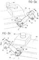
- FIGURES 3a and 3B illustrate a back view of the right and left control arms of the ergonometric control system depicted in FIGURE 1.
- Generally speaking, the invention features a new ergonometric control system for a material handling vehicle, such as a fork lift truck. The control system of the invention is user friendly. The controls have been designed to be comfortable to the vehicle operator, provide easier access to the function actuators, and allow for- simultaneous control of two or more vehicle functions.
- For purposes of clarity and brevity, like components and elements will bear the same designation throughout the figures.
- Now referring to FIGURE 1, a swing-
reach truck 10 is shown, with an operator 9 sitting at the ergonometric controls of this invention. The ergonometric controls are part of an operator compartment described in greater detail hereinbelow. The swing-reach truck 10 is a typical type of material handling vehicle that can benefit from the ergonometric control system of this invention. It is to be understood that this vehicle is one of many vehicles that can utilize the invention, and is displayed herein by way of example. - The swing-
reach truck 10 comprises a pair offorks 12 that are carried upon arotatable frame 13 so that theforks 12 can rotate 180° from facing left with respect to the seated operator 9 (as shown) to facing right. Therotatable frame 13 is rotatively connected toextension arm 14 via a rotatingshaft 15. -
Extension arm 14 is vertically movable upon anauxiliary mast 16 via achain 19, which is carried by a hydraulic cylinder 19a. Thus, theforks 12 are movable up and down (arrow 20). -
Auxiliary mast 16 is horizontally movable along upper andlower racks - Moreover,
forks 12 are extendable fromrotatable frame 13 on a scissor-like mechanism (not shown). This extending action occurs automatically at the end of the horizontal movement ofmast 16 alongracks vehicle 10 and storage racks, not shown. - The
operator platform 18, carrying the operator 9 andauxiliary mast assembly 16, is likewise movable up and down (arrows 22) via amain mast 21 via chains, not shown, which are carried by hydraulic cylinders, not shown. - Referring to FIGURE 2, it will be observed that the
control arms Control arm 25 also carries avehicle steering knob 29, andcontrol arm 24 also carries an emergency power off (EPO) palm depressbutton 26. - On
arm 24 there is mounted acontrol console 27 which includes a powerkey switch 27a, anoperator display 27b and a plurality ofselector switches 27c for work lights and fans. - Referring to FIGURES 3a and 3b, the control handles 30 and 31 are shown in an operating position facing towards the forks. It will be noted that the right control handle 30 is a mirror image of the control handle 31. However, each control arm, with its respective actuators described hereinbelow, controls different functions. The control handles 30 and 31 are shaped to conform to the grip of the operator 9. The respective
contoured surfaces 40 and 41 conform to the clenched hands of the operator, and provide a comfortable grasp of the control handles 30 and 31, respectively. This is important, because these handles can serve to support the operator 9 during the operation and movement of the vehicle. - Control handle 30 controls the vehicle travel direction and speed when it is rotationally displaced about
axis 35. Control handle 31 controls the horizontal displacement and speed ofauxiliary mast 16 alongracks auxiliary mast 16 to the left, while pullinghandle 31moves mast 16 to the right. - The right control handle 30 has a number of distinctive actuators A, B, C and D, which correspond to the actuators A', B', C' and D' disposed on
control handle 31. It will also be observed that each of the respective actuators A, B, C, and D, or A', B', C' and D' on the right or theleft control arms top portions 50 of the control arms. They are located in off-center locations ontop portions 50, necessitating that the thumb of the hand must push upwardly or downwardly (arrows 45 and 46) upon these levers to effectuate lever movement. Lever D controls the lifting or lowering speed of theforks 12 uponmain mast 21, while lever D' controls the rotation direction and speed of the forks with respect to supportarm 14. - The respective flat buttons A and A' control the vehicle horn and the lift/lower selection of the
auxiliary mast 16 respectively, in the lift mode. In operation, button A' is held depressed while lever D is rotated in order to raise or lower theauxiliary mast 16. If lever D is rotated without depressing button A', themain mast 21 is controlled. These buttons must be depressed by the thumb, rather than pushed or pulled, as required for levers D and D', in order to actuate their functions. - Selector switches B and B' respectively control the manual/automatic vehicle travel mode and the fork tilting positions. The manual/automatic vehicle travel mode relates to either driver operated or guided vehicular control. The three-position spring return-to-center selector switch B' allows the
forks 12 to tilt upwardly or downwardly. Selector switch B is a two-position rocker switch, and requires a rocking motion to effect actuation of the desired function. These switches B and B' can generally be actuated by the middle fingers or thumb of the operator's hand. - Finally, the round cap button C, in conjunction with left control handle 31, selects the coordination between rotation of
forks 12 and horizontal traverse ofauxiliary mast 16 alongracks - Thus it will be evident that all of the switches, and the control handles themselves, have different functions, different shapes and feel, and different modes of actuation. In this manner, it is unlikely that an operator will confuse the vehicle function which he desires to invoke with the actuation of these control elements.
- It is also to be noted that each switch, button, lever, etc., including the control handles, is designed to move in a direction that is conceived to be functionally proper by the operator. This tactile awareness also assists in actuating the various functions properly, and avoids costly errors.
- Also, it should be observed that since all the control elements are closely spaced and can be actuated by either hand, it is possible to invoke a plurality (at least two) of functions simultaneously.
- The present invention, by placing all the control functions within finger-tip control, not only eliminates the previous need to move between control levers, but also eliminates large throw distances for actuation. All of the advantages of the invention provide a reduction in energy and effort. At the end of the work shift, the operator will be less tired and fatigued. Also, as aforementioned, the control handles 30 and 31 have been designed to fit comfortably within the operator's hand, in order to reduce fatigue and make the work more enjoyable.
Claims (9)
- An ergonometric control system for material handling vehicles, such as fork lift trucks (10), comprising a pair of respective right and left control handles (30, 31), said handles being disposed about an operator compartment portion of the material handling vehicle for providing control of vehicular functions, said respective right and left control handles conforming to respective right and left hand grips of a vehicle operator (5), and said right and left handles providing operator support throughout vehicle operation.
- The control system in accordance with claim 1, wherein each handle (30, 31) comprises a plurality of closely spaced and easily accessed function actuators (A,A',B,B',C,C',D,D') that are integrated into their respective handle, such that they are within finger tip reach of the operator's hand.
- The control system in accordance with claim 2, wherein the function actuators allow for simultaneous control of two or more vehicular functions.
- The control system in accordance with claims 2 or 3, wherein said actuators (A,A',B,B',C,C'D,D') and handles (30, 31) each provide intuitive sense control, wherein each handle and actuator moves in a same sense as a function for which it is designed.
- The control system in accordance with any of claims 2 to 4, wherein said actuators (A,A',B,B',C,C',D,D') are physically and functionally distinct in how they are accessed, so that they do not cause confusion between particular functions to be controlled.
- The control system in accordance with any preceding claim, wherein said right and left handles (30,31) respectively control forward and backward movement of said material handling vehicle (10), and right and left movement of fork lift truck forks (12).
- The control system in accordance with any of claims 2 to 6, wherein said actuators (A,A',B,B',C,C',D,D') are selected from a group of at least one actuator consisting of: vehicle travel control, a horn control (A), an automatic/manual switch (B) for selecting the manual or automatic control of the vehicle, means (C) for co-ordination of vehicle rotation and auxiliary mast traverse functions, means (D) for raising and lowering the main mast, auxiliary mast traverse and scissor extension/retraction, means (D') for actuating the rotation of the forks, means (A') for selecting the auxiliary mast lift/lower, a selector switch (B') for tilting the forks, and by-pass means (C') for overriding the main mast lift limit.
- The control system in accordance with any preceding claim, wherein said right and left handles (30, 31) respectively control forward and backward movement of said material handling vehicle (10), and right and left movement of fork lift truck forks (12).
- The control system of any preceding claim, wherein the conformity of the control handles (30,31) to the grip of the operator (9) provides operator comfort and ease of vehicle operation.
Applications Claiming Priority (2)
| Application Number | Priority Date | Filing Date | Title |
|---|---|---|---|
| US80217191A | 1991-12-04 | 1991-12-04 | |
| US802171 | 1991-12-04 |
Publications (1)
| Publication Number | Publication Date |
|---|---|
| EP0545676A1 true EP0545676A1 (en) | 1993-06-09 |
Family
ID=25183028
Family Applications (1)
| Application Number | Title | Priority Date | Filing Date |
|---|---|---|---|
| EP92310984A Withdrawn EP0545676A1 (en) | 1991-12-04 | 1992-12-02 | An ergonomic control system for swing reach vehicles |
Country Status (2)
| Country | Link |
|---|---|
| EP (1) | EP0545676A1 (en) |
| CA (1) | CA2084033A1 (en) |
Cited By (8)
| Publication number | Priority date | Publication date | Assignee | Title |
|---|---|---|---|---|
| DE9417838U1 (en) * | 1994-11-08 | 1994-12-22 | Jungheinrich Ag | Manually operated control device for a control station or seat |
| FR2750150A1 (en) * | 1996-06-24 | 1997-12-26 | Caterpillar Inc | Control handle for earthmoving machinery |
| EP1627848A2 (en) * | 2004-08-20 | 2006-02-22 | Jungheinrich Aktiengesellschaft | Industrial truck with ergonomically arranged control elements |
| EP1717187A3 (en) * | 2005-04-26 | 2007-05-30 | Still Gmbh | Industrial truck with a multifunction lever |
| WO2009050745A1 (en) * | 2007-10-17 | 2009-04-23 | Komatsu Utility Europe S.P.A. | Control device for earth moving machines |
| DE102015112816A1 (en) * | 2015-08-04 | 2017-02-09 | Jungheinrich Aktiengesellschaft | Device for actuating a steering device of a truck |
| US10544022B2 (en) | 2016-10-13 | 2020-01-28 | The Raymond Corporation | Handle position sensing systems and methods for a material handling vehicle |
| CN112589817A (en) * | 2020-11-06 | 2021-04-02 | 兰州空间技术物理研究所 | Operation control method of space manipulator |
Citations (9)
| Publication number | Priority date | Publication date | Assignee | Title |
|---|---|---|---|---|
| US4140200A (en) * | 1977-05-27 | 1979-02-20 | J. I. Case Company | Control device and arm support |
| WO1981002208A1 (en) * | 1980-01-24 | 1981-08-06 | Olsbergs Hydraulic Ab | A device for controlling the fluid supply to a number of consumers |
| FR2543322A1 (en) * | 1983-03-24 | 1984-09-28 | Orenstein & Koppel Ag | MANUAL CONTROL POST WITH ERGONOMIC ARRANGEMENT, INTENDED, IN PARTICULAR, FOR PUBLIC WORKS MACHINERY |
| DE3418871A1 (en) * | 1983-05-20 | 1984-11-29 | Kabushiki Kaisha Komatsu Seisakusho, Tokio/Tokyo | Operating device for a construction machine |
| US4896558A (en) * | 1988-06-01 | 1990-01-30 | Deere & Company | Control handle for a work vehicle |
| DE9005392U1 (en) * | 1989-12-22 | 1990-07-19 | Siemens Ag, 1000 Berlin Und 8000 Muenchen, De | |
| US4943756A (en) * | 1989-12-05 | 1990-07-24 | Crown Equipment Corporation | Control of hydraulic systems |
| EP0443829A1 (en) * | 1990-02-21 | 1991-08-28 | J.C. Bamford Excavators Limited | Skid steer vehicle |
| DE9204392U1 (en) * | 1992-04-01 | 1992-05-27 | Licentia Patent-Verwaltungs-Gmbh, 6000 Frankfurt, De |
-
1992
- 1992-11-27 CA CA 2084033 patent/CA2084033A1/en not_active Abandoned
- 1992-12-02 EP EP92310984A patent/EP0545676A1/en not_active Withdrawn
Patent Citations (9)
| Publication number | Priority date | Publication date | Assignee | Title |
|---|---|---|---|---|
| US4140200A (en) * | 1977-05-27 | 1979-02-20 | J. I. Case Company | Control device and arm support |
| WO1981002208A1 (en) * | 1980-01-24 | 1981-08-06 | Olsbergs Hydraulic Ab | A device for controlling the fluid supply to a number of consumers |
| FR2543322A1 (en) * | 1983-03-24 | 1984-09-28 | Orenstein & Koppel Ag | MANUAL CONTROL POST WITH ERGONOMIC ARRANGEMENT, INTENDED, IN PARTICULAR, FOR PUBLIC WORKS MACHINERY |
| DE3418871A1 (en) * | 1983-05-20 | 1984-11-29 | Kabushiki Kaisha Komatsu Seisakusho, Tokio/Tokyo | Operating device for a construction machine |
| US4896558A (en) * | 1988-06-01 | 1990-01-30 | Deere & Company | Control handle for a work vehicle |
| US4943756A (en) * | 1989-12-05 | 1990-07-24 | Crown Equipment Corporation | Control of hydraulic systems |
| DE9005392U1 (en) * | 1989-12-22 | 1990-07-19 | Siemens Ag, 1000 Berlin Und 8000 Muenchen, De | |
| EP0443829A1 (en) * | 1990-02-21 | 1991-08-28 | J.C. Bamford Excavators Limited | Skid steer vehicle |
| DE9204392U1 (en) * | 1992-04-01 | 1992-05-27 | Licentia Patent-Verwaltungs-Gmbh, 6000 Frankfurt, De |
Cited By (9)
| Publication number | Priority date | Publication date | Assignee | Title |
|---|---|---|---|---|
| DE9417838U1 (en) * | 1994-11-08 | 1994-12-22 | Jungheinrich Ag | Manually operated control device for a control station or seat |
| FR2750150A1 (en) * | 1996-06-24 | 1997-12-26 | Caterpillar Inc | Control handle for earthmoving machinery |
| EP1627848A2 (en) * | 2004-08-20 | 2006-02-22 | Jungheinrich Aktiengesellschaft | Industrial truck with ergonomically arranged control elements |
| EP1627848A3 (en) * | 2004-08-20 | 2006-04-05 | Jungheinrich Aktiengesellschaft | Industrial truck with ergonomically arranged control elements |
| EP1717187A3 (en) * | 2005-04-26 | 2007-05-30 | Still Gmbh | Industrial truck with a multifunction lever |
| WO2009050745A1 (en) * | 2007-10-17 | 2009-04-23 | Komatsu Utility Europe S.P.A. | Control device for earth moving machines |
| DE102015112816A1 (en) * | 2015-08-04 | 2017-02-09 | Jungheinrich Aktiengesellschaft | Device for actuating a steering device of a truck |
| US10544022B2 (en) | 2016-10-13 | 2020-01-28 | The Raymond Corporation | Handle position sensing systems and methods for a material handling vehicle |
| CN112589817A (en) * | 2020-11-06 | 2021-04-02 | 兰州空间技术物理研究所 | Operation control method of space manipulator |
Also Published As
| Publication number | Publication date |
|---|---|
| CA2084033A1 (en) | 1993-06-05 |
Similar Documents
| Publication | Publication Date | Title |
|---|---|---|
| EP1346268B1 (en) | Hand grip with microprocessor for controlling a power machine | |
| US20050034549A1 (en) | Device for interactive control with the hand of an operator | |
| EP0095763B1 (en) | A control stick unit | |
| US3811336A (en) | Multi-function controller | |
| KR102412206B1 (en) | Control module and palm rest for a materials handling vehicle | |
| US20020166267A1 (en) | Advanced motor grader controls | |
| EP1717094B1 (en) | Power seat operation switch | |
| EP0686278B1 (en) | Multifunction single lever control for lift trucks | |
| EP0555025B1 (en) | An integrated controls and seating configuration for reach-fork vehicles | |
| EP0545676A1 (en) | An ergonomic control system for swing reach vehicles | |
| US20150033899A1 (en) | Control Element for an Industrial Truck | |
| EP3464781B1 (en) | Control center for an aerial device with control lever | |
| JP2007272837A (en) | Operation lever device of operating machine | |
| JP2943095B2 (en) | Control stick for reach forklift truck | |
| TW510887B (en) | Manipulation levers of forklift and forklift | |
| EP3464160B1 (en) | Control center for an aerial device comprising a rotatable joystick | |
| EP1210287B1 (en) | Operating device for working vehicle | |
| JPH1091263A (en) | Steering device for industrial vehicle | |
| CN215487593U (en) | Ergonomic joystick for a material handling vehicle | |
| US11609594B2 (en) | Steering device for vehicles | |
| JP2002249300A (en) | Forward/backward switching device for forklift | |
| GB2328005A (en) | Arrangement of hand actuated control levers for operating a displacing mast lift truck |
Legal Events
| Date | Code | Title | Description |
|---|---|---|---|
| PUAI | Public reference made under article 153(3) epc to a published international application that has entered the european phase |
Free format text: ORIGINAL CODE: 0009012 |
|
| AK | Designated contracting states |
Kind code of ref document: A1 Designated state(s): DE FR GB IT SE |
|
| 17P | Request for examination filed |
Effective date: 19930705 |
|
| 17Q | First examination report despatched |
Effective date: 19940923 |
|
| STAA | Information on the status of an ep patent application or granted ep patent |
Free format text: STATUS: THE APPLICATION IS DEEMED TO BE WITHDRAWN |
|
| 18D | Application deemed to be withdrawn |
Effective date: 19951214 |