EP0699552A2 - Device for the manual actuation of the accelerator petal of a motor vehicle - Google Patents
Device for the manual actuation of the accelerator petal of a motor vehicle Download PDFInfo
- Publication number
- EP0699552A2 EP0699552A2 EP95113151A EP95113151A EP0699552A2 EP 0699552 A2 EP0699552 A2 EP 0699552A2 EP 95113151 A EP95113151 A EP 95113151A EP 95113151 A EP95113151 A EP 95113151A EP 0699552 A2 EP0699552 A2 EP 0699552A2
- Authority
- EP
- European Patent Office
- Prior art keywords
- potentiometer
- servomotor
- control unit
- regulating
- actuating
- Prior art date
- Legal status (The legal status is an assumption and is not a legal conclusion. Google has not performed a legal analysis and makes no representation as to the accuracy of the status listed.)
- Granted
Links
Images


Classifications
-
- B—PERFORMING OPERATIONS; TRANSPORTING
- B62—LAND VEHICLES FOR TRAVELLING OTHERWISE THAN ON RAILS
- B62D—MOTOR VEHICLES; TRAILERS
- B62D1/00—Steering controls, i.e. means for initiating a change of direction of the vehicle
- B62D1/02—Steering controls, i.e. means for initiating a change of direction of the vehicle vehicle-mounted
- B62D1/04—Hand wheels
-
- B—PERFORMING OPERATIONS; TRANSPORTING
- B60—VEHICLES IN GENERAL
- B60K—ARRANGEMENT OR MOUNTING OF PROPULSION UNITS OR OF TRANSMISSIONS IN VEHICLES; ARRANGEMENT OR MOUNTING OF PLURAL DIVERSE PRIME-MOVERS IN VEHICLES; AUXILIARY DRIVES FOR VEHICLES; INSTRUMENTATION OR DASHBOARDS FOR VEHICLES; ARRANGEMENTS IN CONNECTION WITH COOLING, AIR INTAKE, GAS EXHAUST OR FUEL SUPPLY OF PROPULSION UNITS IN VEHICLES
- B60K26/00—Arrangements or mounting of propulsion unit control devices in vehicles
- B60K26/02—Arrangements or mounting of propulsion unit control devices in vehicles of initiating means or elements
-
- B—PERFORMING OPERATIONS; TRANSPORTING
- B60—VEHICLES IN GENERAL
- B60W—CONJOINT CONTROL OF VEHICLE SUB-UNITS OF DIFFERENT TYPE OR DIFFERENT FUNCTION; CONTROL SYSTEMS SPECIALLY ADAPTED FOR HYBRID VEHICLES; ROAD VEHICLE DRIVE CONTROL SYSTEMS FOR PURPOSES NOT RELATED TO THE CONTROL OF A PARTICULAR SUB-UNIT
- B60W30/00—Purposes of road vehicle drive control systems not related to the control of a particular sub-unit, e.g. of systems using conjoint control of vehicle sub-units, or advanced driver assistance systems for ensuring comfort, stability and safety or drive control systems for propelling or retarding the vehicle
- B60W30/18—Propelling the vehicle
- B60W30/18181—Propulsion control with common controlling member for different functions
-
- B—PERFORMING OPERATIONS; TRANSPORTING
- B60—VEHICLES IN GENERAL
- B60W—CONJOINT CONTROL OF VEHICLE SUB-UNITS OF DIFFERENT TYPE OR DIFFERENT FUNCTION; CONTROL SYSTEMS SPECIALLY ADAPTED FOR HYBRID VEHICLES; ROAD VEHICLE DRIVE CONTROL SYSTEMS FOR PURPOSES NOT RELATED TO THE CONTROL OF A PARTICULAR SUB-UNIT
- B60W2540/00—Input parameters relating to occupants
- B60W2540/10—Accelerator pedal position
Definitions
- the invention relates to a device for manually actuating the accelerator pedal of a motor vehicle with a steering wheel fastened to the steering spindle, furthermore with an actuating wheel which is axially displaceable relative to the steering wheel and rotatable together with it, and with an arrangement for transmitting the axial displacement of the actuating wheel for pedal actuation .
- the actuating wheel can act directly on the power regulator of the motor vehicle engine.
- the Otto engine this is the throttle valve of the carburetor, with the diesel engine, the ice injection pump and with the electric engine, it is an actuator in its power supply.
- manual operation is carried out directly on the accelerator pedal in order to simplify the setup and to keep the vehicle equipped for normal use. Therefore, in the above genre on manual operation referred to the accelerator pedal, but this is not intended to exclude the aforementioned direct power control of the motor vehicle engine.
- the object of the invention is therefore to construct and design a device of the type mentioned at the outset in such a different way that an airbag can be fitted within the steering wheel in the manner customary in series vehicles.
- the device should take up little space in the area of the steering wheel and the steering column and should be easy to retrofit in series vehicles.
- the actuating wheel which is guided axially displaceably on the steering wheel, is connected to the actuating part of a setpoint potentiometer attached to the steering wheel, in that an actuator which can be actuated by an actuating motor attached to the motor vehicle is connected to the accelerator pedal in such a way that the position of the actuator is controlled by a Actual value potentiometer connected to him or the servomotor can be sensed, and that the control motor can be actuated by a regulating and control unit in each case until the values supplied by the potentiometers are compared.
- the subsequent assembly of the device according to the invention is also simple, since practically the entire steering column area, with the exception of the electrical connecting line, remains unaffected, that is to say the input can be made at locations which are easily accessible from the outside.
- the manual actuation of the accelerator pedal according to the invention can be operated without any particular effort, since in addition to the actuating wheel, only the adjusting part of the setpoint potentiometer can be moved, but not an extensive connecting linkage to the accelerator pedal. Therefore, the manual operation according to the invention is also suitable for people whose arms and hands are impaired in their strength.
- the actuating wheel can be guided axially displaceably on the rim of the steering wheel.
- the actuating wheel it has proven to be expedient for the actuating wheel to be guided in at least two axially parallel rods extending from it in a housing fastened to the steering wheel hub. If the actuating wheel then has a rod-shaped chord that traverses it, the rods and the adjusting part of the setpoint potentiometer, the fixed part of which can be arranged on the housing, can emanate from the chord.
- the actuating wheel can be displaced from a rest position, which corresponds to the idling of the motor vehicle engine, against the action of a restoring force, which can be formed by a restoring spring supported on the fixed part of the setpoint potentiometer.
- both training as a linear potentiometer and training as a rotary potentiometer are possible.
- the use of a linear potentiometer should be expedient because of the axial displacement movement of the actuating wheel, which then does not require any additional levers to be implemented on the potentiometer.
- a servomotor which can be driven in both directions, the use of an electric motor being possible for its formation because of the electrical supply which is present anyway.
- a hydraulic motor is also conceivable with regard to the supply of pressure oil that is present at least in motor vehicles with internal combustion engines.
- the actuator of the servomotor is a lever arm which can be pivoted by the servomotor, and that a connecting member extending from the accelerator pedal is articulated at the free end of the lever arm, which is advantageously a rigid component.
- a clutch which can be switched by the regulating and control unit and which can be switched on electrically against the action of a force releasing it can be arranged between the servomotor and the actuator. This ensures that, in the event of a power failure, the accelerator pedal is returned to the idle position under the effect of the normally acting return spring, since the connection between the servomotor and actuator is then interrupted.
- This also ensures that the motor vehicle drive returns to idling in the event of braking or an unforeseen event. So that in one of the cases mentioned the control unit does not continue to attempt to make the servo follow a deflection of the actuating wheel, it can be provided that the control unit can be switched off with respect to the adjustment of the potentiometers during the actuation of the brake light switch and possibly the airbag sensors is.
- a rotary potentiometer or a linear potentiometer can also be considered for the actual value potentiometer.
- a linear potentiometer could work, for example, with the lever arm that can be connected to the servomotor. However, it should be expedient to attach a rotary potentiometer coaxial to the actuator on the actuator.
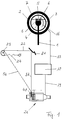
- FIGS 1 and 2 show a steering wheel 2 seated on a steering column 1, in which an actuating wheel 3 is arranged concentrically.
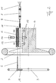
- a housing 5 On the hub 4 of the steering wheel sits a housing 5, via which the actuating wheel 3 is axially displaceable by means of two rods 6 which are essentially perpendicular to the plane of the drawing in FIG.
- the rods 6 are fastened to a chord 7 which crosses the actuating wheel 3 above the steering wheel hub 4.
- the fixed part 8 of a linear potentiometer is seated in or on the housing 5, the adjusting part 9 of which is connected to a tab 10, which is also seated on the chord 7.
- the actuating part 9 is located between the two rods 6.
- a return spring 11 is arranged, which tries to bring the actuating wheel 3 and thus the actuating part 9 into a stop position on the left relative to FIG Motor vehicle engine corresponds.
- the stop position can be formed by the mobility of the adjusting part 9 within the fixed part 8.
- FIG. 2 shows screw connections 12, with which the fixed part 8 on the housing 5 within one there Receiving space 13 is fixed, and a screw 14 for attaching the housing 5 on the steering wheel hub 4th
- An electrical line 15 goes from the linear potentiometer 8, 9 to a slip ring 16 indicated in FIG. 1, from which a line 17 leads to a regulating and control unit 18, which will be discussed in more detail later.
- an electrical connection 19 goes from the regulating and control unit 18 to an actuating unit 20 for the accelerator pedal 21, which in the present case is known in the present case via a connection 22 to the throttle valve 23 of the carburetor of an Otto -Motor is connected.
- a spring 24 engaging the throttle valve 23 ensures that the throttle valve 23 and accelerator pedal 21 are constantly loaded in the sense of a return to the idle position for the vehicle engine.
- the actuating unit 20 has a housing 25 with a recess 26 for receiving an actuating motor 27, the electrical connections 28 of which are connected to the regulating and control unit 18 via the line 19.
- the servomotor 27 is held in the housing 25 by means of an end plate 29, the end plate 29 being fixed to the housing 25 by screws 30.
- the free end of the motor shaft 31 projects into an electromagnetic clutch 32 and is there with the right coupling half 33 rotatably connected.
- the clutch housing is flanged to the housing 25 by means of screws 34.
- the left coupling half 35 is connected to an actuator 36 in the form of a lever arm, at the free end of which a connection 37 to the accelerator pedal 21 is pivoted at 38.
- the connection 37 can have the form of a cable or a rod, the length of which can be finely adjusted by means of a screw 39.
- a bearing seat 40 for the actuating part 41 of a rotary potentiometer Immediately next to the left coupling half 35 and the actuator 36 is a bearing seat 40 for the actuating part 41 of a rotary potentiometer, the actuating part 41 protruding into the left coupling half 35 and being rotationally connected to it.
- the actuating part 41 can be rotated via a needle bearing 42.
- potentiometer seat 43 In addition to the bearing seat 40 there is a potentiometer seat 43 in which the fixed part 44 of the rotary potentiometer is held by means of a cover plate 45. Cover plate 45, potentiometer seat 43 and bearing seat 40 are connected to one another by screws 46. The rotary potentiometer 41, 44 has an electrical connection 47, which also goes via line 19 to the regulating and control unit 18.
- the actuating unit 20 thus described sits between two side plates 48 and 49 and is connected to these by screws 50.
- the side plates 48 and 49 can be part of or connected to the motor vehicle housing.
- FIG. 4 again shows schematically the electrical circuit connection of the components described with the regulating and control unit 18, with the electrical line connection 51 between the coupling 32 and the regulating and control unit and the electrical line connection 52 between the brake light switch 53 and the regulating and control unit also being added 18.
- a device switch is designated, which is connected via a line 55 to the regulating and control unit 18 and is closed by actuating the ignition key for the motor vehicle.
- the device thus described with reference to FIGS. 1 to 4 works as follows: The motor vehicle or its drive motor are in operation, that is to say the device switch 54 is closed, so that the device described with reference to FIGS. 1 to 4 is connected to the energy supply.
- accelerator If accelerator is now to be accelerated, the driver presses or pushes the actuating wheel 3 with respect to FIG. 2 from the left to the right, as a result of which the spring is tensioned and the actuating part 9 of the linear potentiometer 8, 9 is likewise displaced from the left to the right.
- the electrical value generated in this way goes via the slip ring 16 and the line 17 to the regulating and control unit 18, which compares the value of the potentiometer 8, 9 with the control value of the rotary potentiometer 41, 44.
- the servomotor 27 is actuated until the clutch half 33 and thus via the clutch 32 which is switched on the actuator 36 and the actuator 41 of the rotary potentiometer 41, 44 has rotated into a position in which the values supplied by the two potentiometers match.
- the corresponding process takes place in the reverse manner when the actuating wheel is released, in which the spring 11 moves this actuating wheel 3 again from right to left in relation to FIG. 2.
- the servomotor 27 can be rotated or driven in both directions.
- the drive of the servomotor 27 can also be briefly switched off, for example, so that the accelerator pedal 21 is reset by the spring 24 from FIG. 1.
- Opening the clutch 32 is also possible in a manner not shown in more detail if, for example, the airbag sensors respond due to an accident. Finally, the clutch 32 always drops off when the power supply is interrupted for whatever reason.
- the actuating unit 20 also the Power controller of the motor vehicle engine, in the present case the throttle valve 23 can be actuated directly via a connection 56, that is to say either the accelerator pedal 21 can be bypassed, in which case the connection 37 can be omitted, or the accelerator pedal 21 with its connecting parts can be dispensed with entirely.
Abstract
Description
Die Erfindung betrifft eine Vorrichtung zur Handbetätigung des Fahrpedals eines Kraftfahrzeuges mit einem auf der Lenkspindel befestigten Lenkrad, ferner mit einem Betätigungsrad, das gegenüber dem Lenkrad axial verschiebbar und mit diesem Zusammen drehbar ist, sowie mit einer Anordnung zur Übertragung der Axialverschiebung des Betätigungsrades für die Pedalbetätigung.The invention relates to a device for manually actuating the accelerator pedal of a motor vehicle with a steering wheel fastened to the steering spindle, furthermore with an actuating wheel which is axially displaceable relative to the steering wheel and rotatable together with it, and with an arrangement for transmitting the axial displacement of the actuating wheel for pedal actuation .
Mit Hilfe einer derartigen Vorrichtung können körperbehinderte Personen, die nicht in der Lage sind, mit dem Fuß das Fahrpedal, landläufig Gaspedal genannt, zu betätigen, dieses über das Betätigungsrad von Hand betätigen.With the aid of such a device, physically handicapped persons who are not able to operate the accelerator pedal, commonly called the accelerator pedal, can operate it manually using the actuating wheel.
Es ist auch denkbar, daß mit dem Betätigungsrad unmittelbar auf den Leistungsregler des Kraftfahrzeugmotors eingewirkt wird. Das ist beim Otto-Motor die Drosselklappe des Vergasers, beim Diesel-Motor die Eispritzpumpe und beim Elektro-Motor ein Stellglied in dessen Stromzufuhr. Üblicherweise geht man jedoch mit der Handbetätigung unmittelbar auf das Fahrpedal, um die Einrichtung zu vereinfachen und um das Fahrzeug auch für den normalen Gebrauch ausgerüstet zu halten. Daher ist in der vorstehenden Gattung auf die Handbetätigung des Fahrpedals Bezug genommen, ohne daß dadurch jedoch die genannte direkte Leistungsregelung des Kraftfahrzeugmotors ausgeschlossen sein soll.It is also conceivable for the actuating wheel to act directly on the power regulator of the motor vehicle engine. With the Otto engine, this is the throttle valve of the carburetor, with the diesel engine, the ice injection pump and with the electric engine, it is an actuator in its power supply. Usually, however, manual operation is carried out directly on the accelerator pedal in order to simplify the setup and to keep the vehicle equipped for normal use. Therefore, in the above genre on manual operation referred to the accelerator pedal, but this is not intended to exclude the aforementioned direct power control of the motor vehicle engine.
Bekannte Vorrichtungen der eingangs genannten Art arbeiten mechanisch mit Hilfe eines zur Lenksäule parallelen Gestänges zwischen Betätigungsrad und Fahrpedal. Eine solche Vorrichtung ist gerade im Bereich des Lenkrades und der Lenksäule platzgreifend und aufwendig, wodurch insbesondere der nachträgliche Einbau in serienmäßig hergestellte Kraftfahrzeuge erschwert ist. Außerdem erschwert sie die Anbringung eines Airbags innerhalb des Lenkrades oder macht diese gar unmöglich.Known devices of the type mentioned work mechanically with the aid of a linkage parallel to the steering column between the actuating wheel and accelerator pedal. Such a device takes up a lot of space and is expensive, particularly in the area of the steering wheel and the steering column, which makes subsequent installation in series-produced motor vehicles particularly difficult. It also makes it difficult to attach an airbag inside the steering wheel or makes it impossible.
Aufgabe der Erfindung ist es daher, eine Vorrichtung der eingangs genannten Art so anders aufzubauen und gestalten, daß innerhalb des Lenkrades ein Airbag in der bei Serienfahrzeugen üblichen Weise angebracht sein kann. Darüber hinaus soll die Vorrichtung im Bereich des Lenkrades und der Lenksäule kaum Platz beanspruchen und bei Serienfahrzeugen leicht nachträglich anzubringen sein.The object of the invention is therefore to construct and design a device of the type mentioned at the outset in such a different way that an airbag can be fitted within the steering wheel in the manner customary in series vehicles. In addition, the device should take up little space in the area of the steering wheel and the steering column and should be easy to retrofit in series vehicles.
Diese Aufgabe ist erfindungsgemäß dadurchgelöst, daß das am Lenkrad axial verschiebbar geführte Betätigungsrad mit dem Stellteil eines am Lenkrad befestigten Sollwertpotentiometers verbunden ist, daß ein durch einen am Kraftfahrzeug befestigten Stellmotor betätigbares Stellglied mit dem Fahrpedal in Verbindung steht, daß die Position des Stellgliedes durch ein mit ihm bzw. dem Stellmotor verbundenes Istwertpotentiometer abfühlbar ist, und daß durch eine Regel- und Steuereinheit der Stellmotor jeweils bis zum Abgleich der von den Potentiometern gelieferten Werte betätigbar ist.This object is achieved in that the actuating wheel, which is guided axially displaceably on the steering wheel, is connected to the actuating part of a setpoint potentiometer attached to the steering wheel, in that an actuator which can be actuated by an actuating motor attached to the motor vehicle is connected to the accelerator pedal in such a way that the position of the actuator is controlled by a Actual value potentiometer connected to him or the servomotor can be sensed, and that the control motor can be actuated by a regulating and control unit in each case until the values supplied by the potentiometers are compared.
Diese erfindungsgemäßen Maßnahmen haben die Wirkung, daß am Lenkrad nur das Betätigungsrad axial zu führen und ein Sollwertpotentiometer anzubringen ist, was wenig Platz in Anspruch nimmt und leicht so angeordnet werden kann, daß das Lenkrad mit einem Airbag in serienüblicher Weise ausgestattet sein kann. Die Regel- und Steuereinheit sowie Stellmotor, Stellglied und Istwertpotentiometer können entfernt davon, in üblicher Weise nur durch eine elektrische Verbindung gekoppelt an geeigneter Stelle im Kraftfahrzeug untergebracht sein, wo für sie Platz ohnehin vorhanden ist.These measures according to the invention have the effect that only the actuating wheel is to be guided axially on the steering wheel and a setpoint potentiometer is to be fitted, which takes up little space and can easily be arranged in such a way that the steering wheel can be equipped with an airbag in a standard manner. The regulating and control unit as well as the servomotor, actuator and actual value potentiometer can be accommodated at a suitable location in the motor vehicle, in a conventional manner, only coupled by an electrical connection, where there is space for them anyway.
Auch die nachträgliche Montage der erfindungsgemäßen Vorrichtung ist einfach, da praktisch der gesamte Lenksäulenbereich einmal von der elektrischen Verbindungsleitung abgesehen unbeeinträchtigt bleibt, also der Eingabe an von außen leicht zugänglichen Stellen erfolgen kann.The subsequent assembly of the device according to the invention is also simple, since practically the entire steering column area, with the exception of the electrical connecting line, remains unaffected, that is to say the input can be made at locations which are easily accessible from the outside.
Darüber hinaus ist die erfindungsgemäße Handbetätigung des Fahrpedals ohne besonderen Kraftaufwand zu bedienen, da neben dem Betätigungsrad lediglich das Stellteil des Sollwertpotentiometers zu bewegen ist, nicht jedoch ein umfangreiches Verbindungsgestänge zum Fahrpedal. Daher ist die erfindungsgemäße Handbetätigung auch für solche Personen geeignet, deren Arme und Hände in ihrer Kraft beeinträchtigt sind.In addition, the manual actuation of the accelerator pedal according to the invention can be operated without any particular effort, since in addition to the actuating wheel, only the adjusting part of the setpoint potentiometer can be moved, but not an extensive connecting linkage to the accelerator pedal. Therefore, the manual operation according to the invention is also suitable for people whose arms and hands are impaired in their strength.
Für die Führung des Betätigungsrades am Lenkrad sind zahlreiche Möglichkeiten denkbar. So kann das Betätigungsrad beispielsweise am Reif des Lenkrades axial verschiebbar geführt sein. Als zweckmäßig hat es sich jedoch erwiesen, daß das Betätigungsrad über wenigstens zwei von ihm ausgehende, achsparallele Stangen in einem an der Lenkradnabe befestigten Gehäuse geführt ist. Wenn dann das Betätigungsrad eine es durchquerende, stabförmige Sehne aufweist, können von der Sehne die Stangen sowie das Stellteil des Sollwertpotentiometers ausgehen, dessen Festteil am Gehäuse angeordnet sein kann.Numerous possibilities are conceivable for guiding the actuating wheel on the steering wheel. For example, the actuating wheel can be guided axially displaceably on the rim of the steering wheel. However, it has proven to be expedient for the actuating wheel to be guided in at least two axially parallel rods extending from it in a housing fastened to the steering wheel hub. If the actuating wheel then has a rod-shaped chord that traverses it, the rods and the adjusting part of the setpoint potentiometer, the fixed part of which can be arranged on the housing, can emanate from the chord.
In diesem Zusammenhang kann vorgesehen sein, daß das Betätigungsrad aus einer Ruheposition, die dem Leerlauf des Kraftfahrzeugmotors entspricht, gegen die Wirkung einer Rückstellkraft verschiebbar ist, die durch eine am Festteil des Sollwertpotentiometers abgestützte Rückstellfeder gebildet sein kann.In this connection it can be provided that the actuating wheel can be displaced from a rest position, which corresponds to the idling of the motor vehicle engine, against the action of a restoring force, which can be formed by a restoring spring supported on the fixed part of the setpoint potentiometer.
Für das Sollwertpotentiometer kommt grundsätzlich sowohl eine Ausbildung als Linearpotentiometer als auch eine Ausbildung als Drehpotentiometer in Frage. Zweckmäßig dürfte im allgemeinen die Verwendung eines Linearpotentiometers sein wegen der axialen Verschiebebewegung des Betätigungsrades die dann zu ihrer Umsetzung auf das Potentiometer nicht noch zusätzlicher Hebel bedarf.For the setpoint potentiometer, both training as a linear potentiometer and training as a rotary potentiometer are possible. In general, the use of a linear potentiometer should be expedient because of the axial displacement movement of the actuating wheel, which then does not require any additional levers to be implemented on the potentiometer.
Was die elektrische Verbindung zwischen Sollwertpotentiometer und Regel- und Steuereinheit betrifft, so kann in dieser in an sich bekannter Weise eine bewegliche Verbindung über einen Schleifring mit Schleifringkontakten vorgesehen sein.As far as the electrical connection between the setpoint potentiometer and the regulating and control unit is concerned, it can be moved in a manner known per se Connection via a slip ring with slip ring contacts may be provided.
Bezüglich des Stellmotors ist es vorteilhaft, einen in beiden Richtungen drehantreibbaren Stellmotor zu verwenden, für dessen Ausbildung wegen der ohnehin vorhandenen elektrischen Versorgung die Verwendung eines Elektromotors in Frage kommt. Jedoch ist auch die Verwendung eines Hydraulikmotors denkbar im Hinblick auf die zumindest bei Kraftfahrzeugen mit Verbrennungsmotoren vorhandene Versorgung mit Drucköl.With regard to the servomotor, it is advantageous to use a servomotor which can be driven in both directions, the use of an electric motor being possible for its formation because of the electrical supply which is present anyway. However, the use of a hydraulic motor is also conceivable with regard to the supply of pressure oil that is present at least in motor vehicles with internal combustion engines.
Auch für das Stellglied des Stellmotors sind zahlreiche geeignete Ausführungsformen denkbar. Als zweckmäßig erscheint es, daß das Stellglied des Stellmotors ein durch den Stellmotor verschwenkbarer Hebelarm ist, und daß am freien Ende des Hebelarmes ein vom Fahrpedal ausgehendes Verbindungsglied angelenkt ist, welches vorteilhafterweise ein starres Bauteil ist.Numerous suitable embodiments are also conceivable for the actuator of the servomotor. It appears to be expedient that the actuator of the servomotor is a lever arm which can be pivoted by the servomotor, and that a connecting member extending from the accelerator pedal is articulated at the free end of the lever arm, which is advantageously a rigid component.
Aus Sicherheitsgründen kann zwischen Stellmotor und Stellglied eine durch die Regel - und Steuereinheit schaltbare Kupplung angeordnet sein, die elektrisch gegen die Wirkung einer sie lösenden Kraft einschaltbar ist. Hiermit ist dafür gesorgt, daß bei einem eventuellen Stromausfall das Fahrpedal unter der Wirkung der üblicherweise angreifenden Rückholfeder in die Leerlaufstellung zurückgeführt wird, da dann die Verbindung zwischen Stellmotor und Stellglied unterbrochen ist.For safety reasons, a clutch which can be switched by the regulating and control unit and which can be switched on electrically against the action of a force releasing it can be arranged between the servomotor and the actuator. This ensures that, in the event of a power failure, the accelerator pedal is returned to the idle position under the effect of the normally acting return spring, since the connection between the servomotor and actuator is then interrupted.
Im gleichen Sinne ist es vorteilhaft, daß die Regel- und Steuereinheit mit dem Bremslichtschalter sowie gegebenenfalls mit Airbagsensoren in Verbindung steht, und daß bei deren Betätigung das Stellglied durch den Stellmotor sowie das Istwertpotentiometer in die dem Leerlauf des Kraftfahrzeugantriebes entsprechende Position rückführbar und/oder die Kupplung lösbar ist. Auch hiermit ist also dafür Sorge getragen, daß der Kraftfahrzeugantrieb im Falle des Bremsens oder in einem unvorhergesehenen Falle in den Leerlauf zurückgelangt. Damit in einem der genannten Fälle die Regel- und Steuereinheit nicht weiter versucht, den Stellmotor einer Auslenkung des Betätigungsrades folgen zu lassen, kann vorgesehen sein, daß während der Betätigung des Bremslichtschalters sowie gegebenenfalls der Airbagsensoren die Regel- und Steuereinheit bezüglich des Abgleichs der Potentiometer abschaltbar ist.In the same sense, it is advantageous that the regulating and control unit with the brake light switch and, if necessary communicates with airbag sensors, and that when they are actuated, the actuator can be returned to the position corresponding to the idling of the motor vehicle drive and / or the clutch can be released by the servomotor and the actual value potentiometer. This also ensures that the motor vehicle drive returns to idling in the event of braking or an unforeseen event. So that in one of the cases mentioned the control unit does not continue to attempt to make the servo follow a deflection of the actuating wheel, it can be provided that the control unit can be switched off with respect to the adjustment of the potentiometers during the actuation of the brake light switch and possibly the airbag sensors is.
Schließlich kann auch für das Istwertpotentiometer die Verwendung eines Drehpotentiometers oder eines Linearpotentiometers in Frage kommen. Ein Linearpotentiometer könnte beispielsweise mit dem mit dem Stellmotor verbindbaren Hebelarm zusammenarbeiten. Zweckmäßig dürfte aber die Anbringung eines zum Stellmotor koaxialen Drehpotentiometers am Stellglied sein.Finally, the use of a rotary potentiometer or a linear potentiometer can also be considered for the actual value potentiometer. A linear potentiometer could work, for example, with the lever arm that can be connected to the servomotor. However, it should be expedient to attach a rotary potentiometer coaxial to the actuator on the actuator.
Weitere Merkmale und Einzelheiten der Erfindung ergeben sich aus der nachfolgenden Beschreibung einer Ausführungsform, die auf der Zeichnung teilweise vereinfacht dargestellt ist. In der Zeichnungen zeigen:
Figur 1- eine Übersichtsdarstellung der Gesamtvorrichtung;
Figur 2- eine axiale Schnittansicht des Lenkradbereiches in Explosionsdarstellung;
Figur 3- eine teilweise axial geschnittene Seitenansicht der Einheit aus Stellmotor und Stellglied in Explosionsdarstellung und
Figur 4- eine schematische Darstellung der elektrischen Schaltungsanordnung der Vorrichtung.
- Figure 1
- an overview of the overall device;
- Figure 2
- an axial sectional view of the steering wheel area in an exploded view;
- Figure 3
- a partially axially sectioned side view of the unit of actuator and actuator in exploded view and
- Figure 4
- is a schematic representation of the electrical circuitry of the device.
Die Figuren 1 und 2 zeigen ein auf einer Lenksäule 1 sitzendes Lenkrad 2, in dem konzentrisch ein Betätigungsrad 3 angeordnet ist. Auf der Nabe 4 des Lenkrades sitzt ein Gehäuse 5, über welches das Betätigungsrad 3 mittels zweier im wesentlichen zur Zeichenebene der Figur 1 senkrechter Stangen 6 axial verschiebbar ist. Die Stangen 6 sind an einer Sehne 7 befestigt, die das Betätigungsrad 3 oberhalb der Lenkradnabe 4 durchquert.Figures 1 and 2 show a
Wie anhand der Figur 2 näher verdeutlicht, sitzt im oder am Gehäuse 5 das Festteil 8 eines Linearpotentiometers, dessen Stellteil 9 mit einer Lasche 10 verbunden ist, die ebenfalls an der Sehne 7 sitzt. Zweckmäßig liegt das Stellteil 9 zwischen den beiden Stangen 6. Zwischen Feststeil 8 des Linearpotentiometers und Lasche 10 ist eine Rückstellfeder 11 angeordnet, die das Betätigungsrad 3 sowie damit das Stellteil 9 in eine bezogen auf Figur 2 linke Anschlagposition zu bringen trachtet, die dem Leerlauf des Kraftfahrzeugmotors entspricht. Die Anschlagposition kann durch die Beweglichkeit des Stellteiles 9 innerhalb des Festteiles 8 gebildet sein.As illustrated in FIG. 2, the
Figur 2 zeigt noch Schraubverbindungen 12, mit denen das Festteil 8 am Gehäuse 5 innerhalb eines dortigen Aufnahmeplatzes 13 befestigt ist, sowie eine Schraubverbindung 14 zur Anbringung des Gehäuses 5 auf der Lenkradnabe 4.Figure 2 shows
Vom Linearpotentiometer 8, 9 geht eine elektrische Leitung 15 auf einen in Figur 1 angedeuteten Schleifring 16, von dem aus eine Leitung 17 weiterführt zu einer Regel- und Steuereinheit 18, auf die später noch im einzelnen eingegangen wird.An
Wie aus den Figuren 1 und 3 ersichtlich, geht von der Regel- und Steuereinheit 18 aus eine elektrische Verbindung 19 zu einer Stelleinheit 20 für das Fahrpedal 21, das im vorliegenden Falle in bekannter Weise über eine Verbindung 22 an die Drosselklappe 23 des Vergasers eines Otto-Motors angeschlossen ist. Eine an der Drosselklappe 23 angreifende Feder 24 sorgt dafür, daß Drosselklappe 23 und Fahrpedal 21 ständig im Sinne einer Rückstellung zur Leerlaufposition für den Fahrzeugmotor belastet sind.As can be seen from FIGS. 1 and 3, an
Wie aus Figur 3 ersichtlich, weist die Stelleinheit 20 ein Gehäuse 25 mit einer Ausnehmung 26 zur Aufnahme eines Stellmotors 27 auf, dessen elektrische Anschlüsse 28 über die Leitung 19 mit der Regel- und Steuereinheit 18 verbunden sind. Der Stellmotor 27 wird mittels einer Abschlußplatte 29 im Gehäuse 25 gehalten, wobei die Abschlußplatte 29 über Schrauben 30 am Gehäuse 25 festgelegt ist.As can be seen from FIG. 3, the actuating
Das freie Ende der Motorwelle 31 ragt in eine elektromagnetische Schaltkupplung 32 und ist dort mit der rechten Kupplungshälfte 33 drehverbunden. Das Kupplungsgehäuse ist mittels Schrauben 34 am Gehäuse 25 angeflanscht.The free end of the
Die linke Kupplungshälfte 35 ist mit einem Stellglied 36 in Form eines Hebelarmes verbunden, an dessen freiem Ende eine Verbindung 37 zum Fahrpedal 21 bei 38 schwenkbar angelenkt ist. Die Verbindung 37 kann die Form eines Seilzuges oder einer Stange haben, wobei deren Länge über eine Schraube 39 fein einstellbar ist.The
Unmittelbar neben der linken Kupplungshälfte 35 und dem Stellglied 36 ist ein Lagersitz 40 für das Stellteil 41 eines Drehpotentiometers angeordnet, wobei das Stellteil 41 in die linke Kupplungshälfte 35 ragt und mit dieser drehverbunden ist. Im Lagersitz 40 ist das Stellteil 41 über ein Nadellager 42 drehbar.Immediately next to the
Neben dem Lagersitz 40 befindet sich ein Potentiometersitz 43, in welchem das Festteil 44 des Drehpotentiometers mit Hilfe einer Deckelplatte 45 gehalten ist. Deckelplatte 45, Potentiometersitz 43 sowie Lagersitz 40 sind durch Schrauben 46 miteinander verbunden. Das Drehpotentiometer 41, 44 weist einen elektrischen Anschluß 47 auf, der ebenfalls über die Leitung 19 zur Regel- und Steuereinheit 18 geht.In addition to the bearing
Die so beschriebene Stelleinheit 20 sitzt zwischen zwei Seitenplatten 48 und 49 und ist mit diesen durch Schrauben 50 verbunden. Die Seitenplatten 48 und 49 können Teil des Kraftfahrzeuggehäuses oder mit diesem verbunden sein.The actuating
Figur 4 zeigt noch einmal schematisch die elektrische Schaltungsverbindung der beschriebenen Bauteile mit der Regel- und Steuereinheit 18, wobei noch hinzukommt die elektrische Leitungsverbindung 51 zwischen Kupplung 32 und Regel- und Steuereinheit sowie die elektrische Leitungsverbindung 52 zwischen dem Bremslichtschalter 53 und der Regel- und Steuereinheit 18. Mit 54 ist ein Geräteschalter bezeichnet, der über eine Leitung 55 mit der Regel- und Steuereinheit 18 verbunden ist und durch Betätigung des Zündschlüssels für das Kraftfahrzeug geschlossen wird.FIG. 4 again shows schematically the electrical circuit connection of the components described with the regulating and
Die so anhand der Figuren 1 bis 4 beschriebene Vorrichtung arbeitet folgendermaßen:
Das Kraftfahrzeug bzw. dessen Antriebsmotor seien in Betrieb, das heißt der Geräteschalter 54 ist geschlossen, so daß die anhand der Figuren 1 bis 4 beschriebene Vorrichtung an die Energieversorgung angeschlossen ist.The device thus described with reference to FIGS. 1 to 4 works as follows:
The motor vehicle or its drive motor are in operation, that is to say the
Soll nun Gas gegeben werden, so wird durch den Fahrer das Betätigungsrad 3 bezogen auf Figur 2 von links nach rechts gedrückt bzw. geschoben, wodurch die Feder gespannt und das Stellteil 9 des Linearpotentiometers 8, 9 ebenfalls von links nach rechts verschoben wird. Der damit erzeugte elektrische Wert geht über den Schleifring 16 und die Leitung 17 auf die Regel- und Steuereinheit 18, die den Wert des Potentiometers 8, 9 mit dem Stellwert des Drehpotentiometers 41, 44 vergleicht. Stimmen die beiden Werte nicht überein, so wird der Stellmotor 27 betätigt solange, bis er über die eingeschaltete Kupplung 32 die Kupplungshälfte 33 und damit das Stellglied 36 sowie das Stellteil 41 des Drehpotentiometers 41, 44 in eine Position gedreht hat, bei der die von den beiden Potentiometern gelieferten Werte übereinstimmen.If accelerator is now to be accelerated, the driver presses or pushes the
Der entsprechende Vorgang spielt sich in umgekehrter Weise beim Loslassen des Betätigungsrades ab, bei dem die Feder 11 dieses Betätigungsrad 3 wieder bezogen auf Figur 2 von rechts nach links bewegt. Hierzu ist der Stellmotor 27 in beiden Richtungen drehbar bzw. drehantreibbar. Für die Gasrücknahme kann aber beispielsweise auch der Antrieb des Stellmotors 27 kurzzeitig abgeschaltet werden, so daß die Rückstellung des Fahrpedals 21 durch die Feder 24 aus Figur 1 geschieht.The corresponding process takes place in the reverse manner when the actuating wheel is released, in which the
Wird aus irgendeiner Fahrposition heraus die Kraftfahrzeugbremse betätigt, so wird damit der Schalter 53 geschlossen, wodurch die Drehverbindung der Kupplung 32 geöffnet wird, so daß mittels der Feder 24 sofort eine Rückstellung des Gaspedals 21 erfolgen kann. Wird danach die Bremse wieder losgelassen, so schließt die Kupplung 32 wieder und es beginnt der Abgleich der Potentiometer von neuem.If the motor vehicle brake is actuated from any driving position, the
Ein Öffnen der Kupplung 32 kommt auch in nicht näher dargestellter Weise in Frage, wenn beispielsweise durch einen Unfall verursacht die Airbag-Sensoren ansprechen. Schließlich fällt die Kupplung 32 immer auch dann ab, wenn durch welche Ursache auch immer eine Unterbrechung der Stromversorgung eintritt.Opening the clutch 32 is also possible in a manner not shown in more detail if, for example, the airbag sensors respond due to an accident. Finally, the clutch 32 always drops off when the power supply is interrupted for whatever reason.
Nachgetragen sei noch insbesondere zur Darstellung gemäß Figur 1, daß durch die Stelleinheit 20 auch der Leistungsregler des Kraftfahrzeugmotors, im vorliegenden Fall die Drosselklappe 23 unmittelbar über eine Verbindung 56 betätigt werden kann, also entweder das Fahrpedal 21 umgangen werden kann, wobei dann die Verbindung 37 fortfallen kann, oder das Fahrpedal 21 mit seinen Anschlußteilen gänzlich entfallen kann.It should be added in particular to the illustration according to FIG. 1 that the
Claims (19)
dadurch gekennzeichnet,
daß das am Lenkrad (2) axial verschiebbar geführte Betätigungsrad (3) mit dem Stellteil (9) eines am Lenkrad (2) befestigten Sollwertpotentiometers (8, 9) verbunden ist, daß ein durch einen am Kraftfahrzeug befestigten Stellmotor (27) betätigbares Stellglied (36) mit dem Fahrpedal (21) in Verbindung steht, daß die Position des Stellgliedes (36) durch ein mit ihm bzw. dem Stellmotor (27) verbundenes Istwertpotentiometer (41, 44) abfühlbar ist, und daß durch eine Regel- und Steuereinheit (18) der Stellmotor (27) jeweils bis zum Abgleich der von den Potentiometern (8, 9; 41, 44) gelieferten Werte betätigbar ist.Device for manually actuating the accelerator pedal (21) of a motor vehicle with a steering wheel (2) fastened on the steering spindle (1), furthermore with an actuating wheel (3) which can be axially displaced with respect to the steering wheel (2) and rotated together with the latter, and with an arrangement for transmitting the axial displacement of the actuating wheel (3) for pedal actuation,
characterized,
that the actuating wheel (3), which is axially displaceably guided on the steering wheel (2), is connected to the adjusting part (9) of a setpoint potentiometer (8, 9) attached to the steering wheel (2), that an actuator (27) which can be actuated by a servomotor (27) attached to the motor vehicle 36) is connected to the accelerator pedal (21), that the position of the actuator (36) can be sensed by an actual value potentiometer (41, 44) connected to it or the servomotor (27), and by a regulating and control unit ( 18) the servomotor (27) can be actuated until the values supplied by the potentiometers (8, 9; 41, 44) are compared.
dadurch gekennzeichnet,
daß das Betätigungsrad (3) über wenigstens zwei von ihm ausgehende, achsparallele Stangen (6) in einem an der Lenkradnabe (4) befestigten Gehäuse (5) geführt ist.Device according to claim 1,
characterized,
that the actuating wheel (3) over at least two of it outgoing, axially parallel rods (6) is guided in a housing (5) fastened to the steering wheel hub (4).
dadurch gekennzeichnet,
daß das Betätigungsrad (3) eine es durchquerende, stabförmige Sehne (7) aufweist, und daß von der Sehne (7) die Stangen (6) sowie das Stellteil (9) des Sollwertpotentiometers (8, 9) ausgehen.Device according to claim 1 or 2,
characterized,
that the actuating wheel (3) has a rod-shaped chord (7) passing through it, and that the rods (6) and the adjusting element (9) of the setpoint potentiometer (8, 9) extend from the chord (7).
dadurch gekennzeichnet,
daß das Festteil (8) des Sollwertpotentiometers (8, 9) am Gehäuse (5) angeordnet ist.Device according to one of claims 1 to 3,
characterized,
that the fixed part (8) of the setpoint potentiometer (8, 9) is arranged on the housing (5).
dadurch gekennzeichnet,
daß das Betätigungsrad (3) aus einer Ruheposition gegen die Wirkung einer Rückstellkraft (11) verschiebbar ist.Device according to one of claims 1 to 4,
characterized,
that the actuating wheel (3) is displaceable from a rest position against the action of a restoring force (11).
dadurch gekennzeichnet,
daß das Betätigungsrad (3) gegen die Wirkung einer am Festteil (8) des Sollwertpotentiometers (8, 9) abgestützten Rückstellfeder (11) verschiebbar ist.Device according to claim 5,
characterized,
that the actuating wheel (3) can be displaced against the action of a return spring (11) supported on the fixed part (8) of the setpoint potentiometer (8, 9).
dadurch gekennzeichnet,
daß das Sollwertpotentiometer ein Linear- (8, 9) oder ein Drehpotentiometer ist.Device according to one or more of claims 1 to 6,
characterized,
that the setpoint potentiometer is a linear (8, 9) or a rotary potentiometer.
dadurch gekennzeichnet,
daß die vom Sollwertpotentiometer (8, 9) ausgehende elektrische Leitung (15) über einen Schleifring (16) und Schleifringkontakte mit einer zur Regel - und Steuereinheit (18) führenden Leitung (17) verbunden ist.Device according to one or more of claims 1 to 7,
characterized,
that the electrical line (15) emanating from the setpoint potentiometer (8, 9) is connected via a slip ring (16) and slip ring contacts to a line (17) leading to the regulating and control unit (18).
dadurch gekennzeichnet,
daß der Stellmotor (27) in beiden Richtungen drehantreibbar ist.Device according to one or more of claims 1 to 8,
characterized,
that the servomotor (27) can be driven in rotation in both directions.
dadurch gekennzeichnet,
daß der Stellmotor ein Elektromotor (27) ist.Device according to one or more of claims 1 to 9,
characterized,
that the servomotor is an electric motor (27).
dadurch gekennzeichnet,
daß der Stellmotor ein Hydraulikmotor ist.Device according to one or more of claims 1 to 9,
characterized,
that the servomotor is a hydraulic motor.
dadurch gekennzeichnet,
daß das Stellglied des Stellmotors (27) ein durch den Stellmotor (27) verschwenkbarer Hebelarm (36) ist, und daß am freien Ende des Hebelarmes (36) ein vom Fahrpedal (21) ausgehendes Verbindungsglied (37) angelenkt ist.Device according to one or more of claims 1 to 11,
characterized,
that the actuator of the servomotor (27) is a lever arm (36) which can be pivoted by the servomotor (27), and that a connecting member (37) extending from the accelerator pedal (21) is articulated at the free end of the lever arm (36).
dadurch gekennzeichnet,
daß das Verbindungsglied (37) ein starres Bauteil ist.Device according to claim 12,
characterized,
that the connecting link (37) is a rigid component.
dadurch gekennzeichnet,
daß die Regel- und Steuereinheit eine elektrische Regel- und Steuereinheit (18) ist.Device according to one or more of claims 1 to 13,
characterized,
that the regulating and control unit is an electrical regulating and control unit (18).
dadurch gekennzeichnet,
daß zwischen Stellmotor (27) und Stellglied (36) eine durch die Regel- und Steuereinheit (18) schaltbare Kupplung (32) angeordnet ist.Device according to one or more of claims 1 to 14,
characterized,
that a clutch (32) which can be switched by the regulating and control unit (18) is arranged between the servomotor (27) and the actuator (36).
dadurch gekennzeichnet,
daß die Kupplung (32) elektrisch gegen die Wirkung einer sie lösenden Kraft einschaltbar ist.Device according to claim 15,
characterized,
that the clutch (32) can be switched on electrically against the action of a force releasing it.
dadurch gekennzeichnet,
daß die Regel- und Steuereinheit (18) mit dem Bremslichtschalter (53) sowie gegebenenfalls mit Airbag-Sensoren in Verbindung steht, und daß bei deren Betätigung das Stellglied (36) durch den Stellmotor (27) sowie das Istwertpotentiometer (41, 44) in die dem Leerlauf des Kraftfahrzeugantriebes entsprechende Position rückführbar und/oder die Kupplung (32) lösbar ist.Device according to one or more of claims 1 to 16,
characterized,
that the regulating and control unit (18) is connected to the brake light switch (53) and possibly with airbag sensors, and that when they are actuated, the actuator (36) by the servomotor (27) and the actual value potentiometer (41, 44) in the position corresponding to the idling of the motor vehicle drive is traceable and / or the clutch (32) can be released.
dadurch gekennzeichnet,
daß während der Betätigung des Bremslichtschalters (53) sowie gegebenenfalls der Airbag-Sensoren die Regel- und Steuereinheit (18) bezüglich des Abgleichs der Potentiometer (8, 9; 41, 44) abschaltbar ist.Device according to claim 17,
characterized,
that during the actuation of the brake light switch (53) and possibly the airbag sensors, the regulating and control unit (18) can be switched off with respect to the adjustment of the potentiometers (8, 9; 41, 44).
dadurch gekennzeichnet,
daß das Istwertpotentiometer ein Dreh- (41, 44) oder ein Linearpotentiometer ist.Device according to one or more of claims 1 to 18,
characterized,
that the actual value potentiometer is a rotary (41, 44) or a linear potentiometer.
Applications Claiming Priority (3)
| Application Number | Priority Date | Filing Date | Title |
|---|---|---|---|
| DE4431098 | 1994-09-01 | ||
| DE4431098 | 1994-09-01 | ||
| DE9414152U DE9414152U1 (en) | 1994-09-01 | 1994-09-01 | Device for handling the accelerator pedal of a motor vehicle |
Publications (3)
| Publication Number | Publication Date |
|---|---|
| EP0699552A2 true EP0699552A2 (en) | 1996-03-06 |
| EP0699552A3 EP0699552A3 (en) | 1996-04-03 |
| EP0699552B1 EP0699552B1 (en) | 1997-11-05 |
Family
ID=38353252
Family Applications (1)
| Application Number | Title | Priority Date | Filing Date |
|---|---|---|---|
| EP95113151A Expired - Lifetime EP0699552B1 (en) | 1994-09-01 | 1995-08-22 | Device for the manual actuation of the power control member of a motor vehicle |
Country Status (4)
| Country | Link |
|---|---|
| EP (1) | EP0699552B1 (en) |
| AT (1) | ATE159901T1 (en) |
| DE (1) | DE9414152U1 (en) |
| ES (1) | ES2109762T3 (en) |
Cited By (7)
| Publication number | Priority date | Publication date | Assignee | Title |
|---|---|---|---|---|
| FR2747966A1 (en) * | 1996-04-26 | 1997-10-31 | Sarl Humeau | Speed control system for motor vehicle, esp. for use by handicapped person |
| EP0865958A1 (en) * | 1997-03-19 | 1998-09-23 | GUIDOSIMPLEX s.n.c. di Giancarlo Venturini e C. | Device for the transmission of acceleration and/or braking and/or clutch controls from a vehicle steering wheel |
| EP0829388A3 (en) * | 1996-09-13 | 1998-11-04 | Fadiel Italiana S.R.L. | Control device for a vehicle accelerator |
| EP0970839A1 (en) * | 1998-07-10 | 2000-01-12 | Sarl P.M.T.L. | Device for transforming at least one foot-operated control of a vehicle into a hand-operated control |
| WO2001008918A1 (en) * | 1999-07-30 | 2001-02-08 | Guidosimplex S.N.C. Di Giancarlo Venturini & C. | Stering wheel mounted manual control device, particularly for acceleration |
| WO2004050412A1 (en) * | 2002-12-02 | 2004-06-17 | Guidosimplex Snc Di Giancarlo Venturini & C. | Device for manual acceleration provided above the steering wheel |
| FR2917342A1 (en) * | 2007-06-13 | 2008-12-19 | Pimas Orthopedie Soc Par Actio | Accelerator control device for motor vehicle, has assembling unit provided on steering wheel, and potentiometer connected to remote electrical unit by wire, where wire is connected with socket |
Families Citing this family (2)
| Publication number | Priority date | Publication date | Assignee | Title |
|---|---|---|---|---|
| ITRM950095A1 (en) * | 1995-02-17 | 1996-08-19 | Dario Spinnato | DEVICE WITH ANATOMICAL GRIP, FOR STEERING WHEELS OF MOTOR VEHICLES WITH ELECTRONIC ACCELERATOR SYSTEM. |
| ITTO20120912A1 (en) | 2012-10-16 | 2014-04-17 | Carrozzeria 71 S R L | MANUAL DEVICE OF THE ACCELERATOR OF A MOTOR VEHICLE " |
Family Cites Families (7)
| Publication number | Priority date | Publication date | Assignee | Title |
|---|---|---|---|---|
| US4078628A (en) * | 1976-08-16 | 1978-03-14 | The United States Of America As Represented By The Department Of Health, Education And Welfare | Double-wheel automotive hand control system |
| IT1193612B (en) * | 1983-01-24 | 1988-07-21 | Bruno Gianini | ACCELERATION CONTROL DEVICE FOR CARS INTENDED FOR USERS PHYSICALLY CALLED IN THE LOWER LIMBS |
| EP0324531B1 (en) * | 1986-04-16 | 1995-06-07 | General Motors Corporation | Brake-initiated release of an electric motor driven cruise control apparatus |
| GB2219637B (en) * | 1988-06-08 | 1992-05-06 | Mitsubishi Electric Corp | Electromagnetic clutch in motor-powered drive device |
| US5103125A (en) * | 1989-07-28 | 1992-04-07 | Ogden Ronald H | Electronic control adapter for mechanical throttle control |
| FR2689462A1 (en) * | 1992-04-07 | 1993-10-08 | Rivas Francisco | Motor vehicle control installation for lower limb handicapped drivers |
| IT1262377B (en) * | 1993-07-16 | 1996-06-19 | Giancarlo Venturini | STRUCTURE FOR MANUAL ACCELERATION IN A VEHICLE. |
-
1994
- 1994-09-01 DE DE9414152U patent/DE9414152U1/en not_active Expired - Lifetime
-
1995
- 1995-08-22 AT AT95113151T patent/ATE159901T1/en not_active IP Right Cessation
- 1995-08-22 EP EP95113151A patent/EP0699552B1/en not_active Expired - Lifetime
- 1995-08-22 ES ES95113151T patent/ES2109762T3/en not_active Expired - Lifetime
Non-Patent Citations (1)
| Title |
|---|
| None |
Cited By (8)
| Publication number | Priority date | Publication date | Assignee | Title |
|---|---|---|---|---|
| FR2747966A1 (en) * | 1996-04-26 | 1997-10-31 | Sarl Humeau | Speed control system for motor vehicle, esp. for use by handicapped person |
| EP0829388A3 (en) * | 1996-09-13 | 1998-11-04 | Fadiel Italiana S.R.L. | Control device for a vehicle accelerator |
| EP0865958A1 (en) * | 1997-03-19 | 1998-09-23 | GUIDOSIMPLEX s.n.c. di Giancarlo Venturini e C. | Device for the transmission of acceleration and/or braking and/or clutch controls from a vehicle steering wheel |
| EP0970839A1 (en) * | 1998-07-10 | 2000-01-12 | Sarl P.M.T.L. | Device for transforming at least one foot-operated control of a vehicle into a hand-operated control |
| FR2780922A1 (en) * | 1998-07-10 | 2000-01-14 | P M T L | DEVICE FOR STEERING WHEEL OF A MOTOR VEHICLE WITH ONE OR MORE OF THE FOOT CONTROLS OF THE LATEST |
| WO2001008918A1 (en) * | 1999-07-30 | 2001-02-08 | Guidosimplex S.N.C. Di Giancarlo Venturini & C. | Stering wheel mounted manual control device, particularly for acceleration |
| WO2004050412A1 (en) * | 2002-12-02 | 2004-06-17 | Guidosimplex Snc Di Giancarlo Venturini & C. | Device for manual acceleration provided above the steering wheel |
| FR2917342A1 (en) * | 2007-06-13 | 2008-12-19 | Pimas Orthopedie Soc Par Actio | Accelerator control device for motor vehicle, has assembling unit provided on steering wheel, and potentiometer connected to remote electrical unit by wire, where wire is connected with socket |
Also Published As
| Publication number | Publication date |
|---|---|
| ES2109762T3 (en) | 1998-01-16 |
| ATE159901T1 (en) | 1997-11-15 |
| EP0699552A3 (en) | 1996-04-03 |
| EP0699552B1 (en) | 1997-11-05 |
| DE9414152U1 (en) | 1994-10-20 |
Similar Documents
| Publication | Publication Date | Title |
|---|---|---|
| DE19524941B4 (en) | load adjusting | |
| DE60117274T2 (en) | REAR LOCKING FOR VEHICLES | |
| DE69934417T2 (en) | DEVICE ON AN ACTUATING HANDLE OF A PARKING BRAKE | |
| DE4390096C2 (en) | Control valve controlling device, e.g. for vehicle fuel supply control | |
| EP0699552B1 (en) | Device for the manual actuation of the power control member of a motor vehicle | |
| DE3510642C2 (en) | ||
| DE4142810C2 (en) | Throttle valve control device | |
| AT395896B (en) | DEVICE FOR CONTROLLING AN INJECTION PUMP OF AN INJECTION INTERNAL COMBUSTION ENGINE | |
| EP0123731A1 (en) | Device for transmitting the position of a control element | |
| EP0306640A2 (en) | Electric control device for the throttle of an explosive mixture throttling device of combustion engines | |
| EP0269780A1 (en) | Transmission system for the position of a control element operable by the driver of a vehicle | |
| DE3813047A1 (en) | ADJUSTING DEVICE FOR THE THROTTLE VALVE OF A MIXING FORMING DEVICE FOR INTERNAL COMBUSTION ENGINES | |
| DE4406836A1 (en) | Neutral-position starting switch and fuse alarm switch and a method for their assembly for the purpose of manual displacement control for a hydrostatic drive | |
| DE69816956T2 (en) | Redundant control valve | |
| EP0978402B1 (en) | Actuating device for adjusting movable parts in vehicles | |
| EP0306641A1 (en) | Electric throttle valve control for an internal-combustion engine | |
| DE2856294A1 (en) | DEVICE FOR REGULATING THE SPEED OF A MOTOR VEHICLE | |
| AT406850B (en) | DRIVING DEVICE FOR A CLOSING DEVICE OF A VEHICLE TANK FILLING CONNECTOR | |
| DE1810196B2 (en) | Device for supplying additional air into the intake line of an internal combustion engine | |
| DE3407125A1 (en) | Fastening arrangement on a motor vehicle | |
| DE3045568C2 (en) | Motor drive for low-voltage circuit breakers | |
| WO2000076842A1 (en) | Device for controlling an engine | |
| DE2311198C3 (en) | Actuator for fuel metering for an internal combustion engine | |
| DE3825793C2 (en) | Load adjustment device intended for an internal combustion engine | |
| EP0478884B1 (en) | Load control apparatus |
Legal Events
| Date | Code | Title | Description |
|---|---|---|---|
| PUAI | Public reference made under article 153(3) epc to a published international application that has entered the european phase |
Free format text: ORIGINAL CODE: 0009012 |
|
| PUAL | Search report despatched |
Free format text: ORIGINAL CODE: 0009013 |
|
| AK | Designated contracting states |
Kind code of ref document: A2 Designated state(s): AT DE ES FR IT |
|
| AK | Designated contracting states |
Kind code of ref document: A3 Designated state(s): AT DE ES FR IT |
|
| 17P | Request for examination filed |
Effective date: 19960607 |
|
| 17Q | First examination report despatched |
Effective date: 19960724 |
|
| GRAG | Despatch of communication of intention to grant |
Free format text: ORIGINAL CODE: EPIDOS AGRA |
|
| GRAH | Despatch of communication of intention to grant a patent |
Free format text: ORIGINAL CODE: EPIDOS IGRA |
|
| GRAH | Despatch of communication of intention to grant a patent |
Free format text: ORIGINAL CODE: EPIDOS IGRA |
|
| GRAA | (expected) grant |
Free format text: ORIGINAL CODE: 0009210 |
|
| AK | Designated contracting states |
Kind code of ref document: B1 Designated state(s): AT DE ES FR IT |
|
| REF | Corresponds to: |
Ref document number: 159901 Country of ref document: AT Date of ref document: 19971115 Kind code of ref document: T |
|
| ITF | It: translation for a ep patent filed |
Owner name: ING. C. GREGORJ S.P.A. |
|
| REF | Corresponds to: |
Ref document number: 59500944 Country of ref document: DE Date of ref document: 19971211 |
|
| REG | Reference to a national code |
Ref country code: ES Ref legal event code: FG2A Ref document number: 2109762 Country of ref document: ES Kind code of ref document: T3 |
|
| ET | Fr: translation filed | ||
| PLBE | No opposition filed within time limit |
Free format text: ORIGINAL CODE: 0009261 |
|
| STAA | Information on the status of an ep patent application or granted ep patent |
Free format text: STATUS: NO OPPOSITION FILED WITHIN TIME LIMIT |
|
| 26N | No opposition filed | ||
| PGFP | Annual fee paid to national office [announced via postgrant information from national office to epo] |
Ref country code: ES Payment date: 20020619 Year of fee payment: 8 |
|
| PGFP | Annual fee paid to national office [announced via postgrant information from national office to epo] |
Ref country code: FR Payment date: 20020828 Year of fee payment: 8 |
|
| PGFP | Annual fee paid to national office [announced via postgrant information from national office to epo] |
Ref country code: AT Payment date: 20020829 Year of fee payment: 8 |
|
| PG25 | Lapsed in a contracting state [announced via postgrant information from national office to epo] |
Ref country code: AT Free format text: LAPSE BECAUSE OF NON-PAYMENT OF DUE FEES Effective date: 20030822 |
|
| PGFP | Annual fee paid to national office [announced via postgrant information from national office to epo] |
Ref country code: DE Payment date: 20030822 Year of fee payment: 9 |
|
| PG25 | Lapsed in a contracting state [announced via postgrant information from national office to epo] |
Ref country code: ES Free format text: LAPSE BECAUSE OF NON-PAYMENT OF DUE FEES Effective date: 20030823 |
|
| PG25 | Lapsed in a contracting state [announced via postgrant information from national office to epo] |
Ref country code: FR Free format text: LAPSE BECAUSE OF NON-PAYMENT OF DUE FEES Effective date: 20040430 |
|
| REG | Reference to a national code |
Ref country code: FR Ref legal event code: ST |
|
| REG | Reference to a national code |
Ref country code: ES Ref legal event code: FD2A Effective date: 20030823 |
|
| PG25 | Lapsed in a contracting state [announced via postgrant information from national office to epo] |
Ref country code: DE Free format text: LAPSE BECAUSE OF NON-PAYMENT OF DUE FEES Effective date: 20050301 |
|
| PG25 | Lapsed in a contracting state [announced via postgrant information from national office to epo] |
Ref country code: IT Free format text: LAPSE BECAUSE OF NON-PAYMENT OF DUE FEES;WARNING: LAPSES OF ITALIAN PATENTS WITH EFFECTIVE DATE BEFORE 2007 MAY HAVE OCCURRED AT ANY TIME BEFORE 2007. THE CORRECT EFFECTIVE DATE MAY BE DIFFERENT FROM THE ONE RECORDED. Effective date: 20050822 |