EP0797026A2 - Friction wheel drive - Google Patents
Friction wheel drive Download PDFInfo
- Publication number
- EP0797026A2 EP0797026A2 EP97104664A EP97104664A EP0797026A2 EP 0797026 A2 EP0797026 A2 EP 0797026A2 EP 97104664 A EP97104664 A EP 97104664A EP 97104664 A EP97104664 A EP 97104664A EP 0797026 A2 EP0797026 A2 EP 0797026A2
- Authority
- EP
- European Patent Office
- Prior art keywords
- friction wheel
- friction
- driven
- wheel drive
- drive
- Prior art date
- Legal status (The legal status is an assumption and is not a legal conclusion. Google has not performed a legal analysis and makes no representation as to the accuracy of the status listed.)
- Granted
Links
Images


Classifications
-
- F—MECHANICAL ENGINEERING; LIGHTING; HEATING; WEAPONS; BLASTING
- F16—ENGINEERING ELEMENTS AND UNITS; GENERAL MEASURES FOR PRODUCING AND MAINTAINING EFFECTIVE FUNCTIONING OF MACHINES OR INSTALLATIONS; THERMAL INSULATION IN GENERAL
- F16H—GEARING
- F16H15/00—Gearings for conveying rotary motion with variable gear ratio, or for reversing rotary motion, by friction between rotary members
- F16H15/02—Gearings for conveying rotary motion with variable gear ratio, or for reversing rotary motion, by friction between rotary members without members having orbital motion
-
- Y—GENERAL TAGGING OF NEW TECHNOLOGICAL DEVELOPMENTS; GENERAL TAGGING OF CROSS-SECTIONAL TECHNOLOGIES SPANNING OVER SEVERAL SECTIONS OF THE IPC; TECHNICAL SUBJECTS COVERED BY FORMER USPC CROSS-REFERENCE ART COLLECTIONS [XRACs] AND DIGESTS
- Y10—TECHNICAL SUBJECTS COVERED BY FORMER USPC
- Y10S—TECHNICAL SUBJECTS COVERED BY FORMER USPC CROSS-REFERENCE ART COLLECTIONS [XRACs] AND DIGESTS
- Y10S56/00—Harvesters
- Y10S56/22—Underslung yieldable rotary mower
Definitions
- the invention relates to a friction wheel drive according to the preamble of claim 1 or 2.
- Friction wheel drives or friction gear transmissions are inexpensive to produce transmission elements and generally consist of friction wheels or friction disks with smooth circumferential surfaces that are pressed against each other in such a way that the resulting friction transfers forces or torques.
- One application is hand-held snow removal equipment (John Deere publication from August 1994 with the title: John Deere Snow Removal Equipment).
- a friction wheel is arranged on a horizontal shaft, which is optionally brought to bear against a friction disk which is driven by the output shaft of a motor.
- the friction wheel rotates with the disc and is used to drive wheels above chains and sprockets.
- the friction wheel can assume a neutral position in which the operator can adjust it so that there is no longer any contact with the disc.
- the object to be achieved with the invention provides that the adjustment paths for reversing the direction are kept relatively small.
- the invention therefore provides that a second friction disk is provided on the drivable shaft at a distance from the first friction disk and that the friction wheel can be pivoted between three positions such that the friction wheel lies against the first friction disk in the first position and in a first direction of rotation it is drivable that the friction wheel in the second position bears against the second friction disk and can be driven in a second direction of rotation opposite to the first direction of rotation and that the friction wheel in the third position is at a distance from the first and second friction disk and cannot be driven.
- the invention provides that a second friction disk is provided on the driven part at a distance from the first friction disk and that the friction wheel can be pivoted between three positions or the driven part can be adjusted such that the first friction disk lies against the friction wheel in the first position and can be driven in a first direction of rotation, that the second friction disk rests against the friction wheel in the second position and can be driven in a second direction of rotation opposite to the first direction of rotation, and that the first and second friction disks are at a distance from the friction wheel in the third position and cannot be driven.
- This alternative is in itself a reversal of the first solution. Both solutions have a swiveling friction wheel that is driven once and can also be driven on the other. Alternatively, the friction discs can also be adjusted. In all cases, the travel ranges are very small.
- Such friction wheel drives can also be used without problems in vehicles, in particular in vehicles for lawn and property maintenance, and not only for wheel drives there.
- an internal combustion engine provided on a vehicle is recommended as the power source.
- the friction wheel drive is used as a lifting device, which is why the driven part of the friction wheel drive is connected to a lifting device for lifting and lowering a device depending on the direction of rotation of the friction wheel drive.
- the device is raised, for example, when the driven part rotates in one direction of rotation and lowered when the driven part rotates in the opposite direction.
- the lifting movement is interrupted or the lifting or lowering is completed. This means that there is no need for hydraulic cylinders or complex linkage devices, which have been used many times to raise and lower an implement. No muscle strength needs to be used to adjust the height of the device.
- Devices of this type are generally provided with drivable components which are driven by belt drives, which is why it is further proposed according to the invention that at least one friction disk is designed as a pulley.
- the power flow from the engine to the transmission is conducted via a belt drive.
- Such vehicles then have a drive shaft, which is connected to the motor and is usually directed vertically downward, on which a pulley for driving the tools of the device and, if appropriate, a pulley for the power transmission to the transmission is provided.
- the invention now uses this drive shaft for the friction wheel drive, since it is further proposed according to the invention that the drivable shaft serves to drive the drive wheels of a vehicle and to drive the tools of the device, the device being connected to the vehicle in a height-adjustable manner.
- the parts additionally required for the friction wheel drive thus only consist of the friction wheel with its shaft, since the belt pulleys also serve as a friction disk depending on their outer diameter.
- the friction wheel is then to be provided between the two pulleys and only needs to be pivoted upwards or downwards in order to be able to be driven in different directions of rotation. If the friction wheel is then in an intermediate position in which it has no contact with the disks, its drive is interrupted.
- the drive section can work like a winch to raise and lower the device.
- the driven part interacts with a sliding part which converts the rotary movement of the driven part into a sliding movement running in the direction of the longitudinal axis of the driven part and actuates a lifting linkage at least for lifting the device during its adjustment.
- the driven part is designed as a threaded rod connected to the friction wheel and that the sliding part is non-rotatably guided on the thread of the threaded rod, the threaded rod being pivotably mounted together with the friction wheel and the sliding part cooperating with a pivoting lever which cooperates with the Lifting rod is connected, wherein the threaded rod and the pivot lever are vertically pivoted in a fixed support which has at least one cam surface for automatically returning the friction wheel to its neutral position.
- the friction wheel, threaded rod and pivot lever are pivotally mounted on the support bracket, which is preferably attached to the vehicle, wherein the friction wheel and the threaded rod can be arranged in a support bracket which can then be pivoted in the support bracket.
- the support bracket can be designed so that it prevents the sliding part turns when the threaded rod turns.
- the sliding part is also expediently not connected to the swivel lever, but is only in contact with it when it is lifted, so that the lifting linkage does not participate in the swivel movements of the friction wheel and the threaded rod.
- the invention provides that the friction wheel drive is used to adjust the height of a mower connected to a lawn tractor, the drivable shaft of the friction wheel drive serving to drive at least the knives or the knife of the mower, and the friction wheel being manually adjustable from the driver's position is.
- the existing mower blade drive is still used to adjust the height of the mower.
- the drive system can also be derived from the shaft driving the mower. The only muscle power that is required to adjust the mower is that which must be used to adjust the friction wheel. This is low, but can be somewhat larger if the friction wheel is adjusted against the action of a spring so that the friction wheel returns to its third or neutral position under spring action.
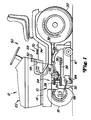
- a lifting device 10 is shown for a preferred embodiment.
- the lifting device 10 is designed for a mower that can be connected to a lawn tractor 12.
- the lawn tractor 12 can be seen in FIG. 1 and is provided with a frame 14 which the mower housing 16 of the mower can be connected.
- the mower housing 16 is located below the frame 14 between the two steerable front wheels 18 and the two drivable rear wheels 20.
- the vehicle 12 is equipped with a drive source or an internal combustion engine 22 which drives the rear wheels 20, the or the Knife of the mower housing 16 and other components or devices has an output shaft.
- the high pulley 24 consists of a central shaft 26 and two rotatably connected to it and having a vertical distance from each other face plates or pulleys 28 and 30.
- a drive belt 32 Around the first pulley 28 is a drive belt 32 which extends rearward to the vehicle transmission, not shown, and ultimately to Drive of the two rear wheels 20 is used.
- a belt 34 is guided around the second and lower pulley 30 and is used to drive the mower blades of the mower housing, which is why corresponding pulleys 36 are provided on the mower housing 16.
- the mower can either be raised or lowered using the lifting device 10.
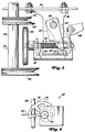
- the lifting device is initially equipped with a friction wheel 38, which is provided between the upper and the lower pulley 28 and 30 and can be adjusted from its neutral position shown in FIG. 3 to a position according to FIG. 6 or 7, so that a friction wheel transmission with Change of direction arises.
- An output part which can be set in rotation is connected in a rotationally fixed manner to the friction wheel 38 and, in the preferred exemplary embodiment, is designed as a threaded rod 40. And so that the friction wheel 38 can be pivoted between its positions, the threaded rod 40 is rotatably mounted in a pivotable support bracket 42.
- the support bracket 42 can be pivoted in a support bracket 46, which can be U-shaped and is then screwed to the vehicle frame with its leg ends.
- the support bracket 42 is then pivoted vertically via a horizontally arranged pin 44 between the legs of the support beam 46.
- the support bracket 42 is adjusted from the driver's cab, which is why the support bracket 42 is firmly connected, for example screwed, to a rearward-facing control arm 49, to which an actuating lever 48 leading to the operating or driver's cab 50 is articulated.
- This engages with its other end on a hand lever 52 provided on the driver's cab and mounted in the vehicle frame 14, so that when the hand lever is adjusted upward by the operator, the mower is raised. The mower is lowered when the hand lever is adjusted downwards.
- An internally threaded sliding part 54 is adjustable on the threaded rod 40 when the threaded rod rotates.
- the sliding part 54 is also provided with laterally protruding projections or sections 55 which adjust the connecting linkage to adjust the height of the mower when the part 54 is adjusted on the spindle 40.
- this linkage includes a U-shaped lever 56, the legs of which abut against the projections 54 at their lower end and are seated in a rotationally fixed manner with their upper ends on a transverse shaft 58, which in turn is mounted in the legs of the support bracket 46.
- On the cross shaft 58 is also a non-rotatably mounted boom 60, the other end via a link 62 on the Mower housing 16 attacks.
- the mower housing is adjusted upwards or downwards.
- the linkage 62 engages the rear portion of the mower deck, the front portion 64 of which is suspended from a support post 66 which is pivotally connected to the vehicle.
- the support bracket thus carries the front section of the mower housing, even if it is moved up and down.
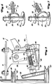
- the preferred embodiment is also equipped with a cutting height adjustment device 68.
- This is actuated via an adjusting button 70, which can be seen in FIGS. 1 and 2, is provided on the driver's cab 50 and is seated on a shaft 72 which extends through the floor 74 of the driver's cab into this.
- the other end of the shaft 72 is connected to a step wheel 76 (see FIGS. 2 and 4), the individual steps of which are designated by 78.
- a height adjusting lever 80 which is connected to the boom 60 via a strut 82, comes into contact and thereby determines the cutting height.
- the height adjustment lever 80 is connected to the lifting linkage 62 and pivots about its connection point in the form of a shaft 84 when the mower housing is raised or lowered.
- the operator moves the hand lever 52 upwards, as a result of which the setting lever 48 is moved downwards.
- the support bracket 42 and the control arm 49 move clockwise from the position shown in FIG. 3 and the friction wheel 38 upwards until it comes into contact with a friction disk 89, which in the preferred embodiment has a larger diameter than the upper pulley 28 , but can be directly underneath it and rotates with it.
- the friction disk 89 rotates, the friction wheel 38 and its spindle 40 rotate in the direction of arrow A in FIG. 6 and the sliding part 54 adjusts in the direction of arrow B in 6, that is to the front and towards the friction wheel 38.
- the friction wheel In the position shown in FIG. 3, the friction wheel has neither contact with the friction disk 89 nor with the lower pulley 30. The friction wheel 38 can then not rotate and the mower housing 16 can not be adjusted in height. This position is called the neutral position.
- the preferred embodiment is also provided with a device 92 which causes the control arm 49 and the support bracket 42 to be returned to their neutral position, in which the friction wheel has no contact with the friction disk 89 or with the lower pulley 30, when the Operator releases the hand lever 52.
- the return is effected by a metallic leaf spring 94 which is connected to the frame 14 and to the control arm 49.
- the cutting height adjustment device 68 of the preferred embodiment is best seen in FIGS. 2 and 4.
- the operator can easily adjust the desired cutting height by turning the knob 70.
- the mower is then lowered again by operating the hand lever 52.
- the mower lowers due to its own weight until the height adjustment lever 80 comes to rest against a step 78 of the step wheel 76.
- Each step corresponds to a certain cutting height, and that In this way, the operator can easily find the selected cutting height after lifting the mower.
- an elongated hole 100 is provided in the strut 82 of the preferred exemplary embodiment, which ensures the function of the cam surface 96 when a cutting height adjustment device 68 is provided. It has already been pointed out that when the mower housing 16 is lowered to a predetermined cutting height, the height adjustment lever 80 comes to bear against the step wheel 76. In such a case, the height adjustment lever 80, the shaft 84 and the boom 86 can no longer pivot clockwise with reference to FIG. 2 and the mower is blocked against further lowering. On the other hand, the friction wheel 38 is then still driven by the lower pulley 30, so that the sliding part 54 moves further backwards.
- the lever 56, the arm 60 and the strut 82 can, if necessary, move backwards, which is then also possible due to the slot 100 provided in the strut, even if the height adjustment lever 80 bears against the step wheel 76.
- the slot thus creates a lost motion connection.
- the sliding part 54 will generally adjust on the spindle 40 until it comes to bear against the first cam surface 96. When the sliding part comes into contact with the first cam surface, the sliding part will move downward, thereby returning the pivotable support bracket 42 with the friction wheel to the neutral position according to FIG. 3.
- the lost motion connection allows the operator to preselect or set a cutting height and then, regardless of the cutting height, can hold the hand lever 52 in the lower position for any length of time because the lifting device automatically returns to the neutral position. Without such a function, the operator would have to let go of the hand lever when the desired cutting height is reached.
- the lifting device 10 described above is thus ultimately driven by the internal combustion engine 22 of the vehicle and can be easily operated by an operator without having to use large or large muscle forces to raise or lower the mower deck, which has a considerable weight in the case of several knives.
- no hydraulic cylinders or complex linkage devices are required, which would make the lifting device considerably more expensive.
- the basic concept of the present invention can also be used in a friction wheel transmission for driving a device or the drive wheels of a vehicle.
- the threaded spindle could be connected as a driven part 40 to a drive shaft which serves to drive the wheels of a manually operated lawn mower, a snow blower or a sweeper.
- the simple pivoting of the friction wheel between its upper and lower positions would then result in a direction of rotation for forward travel and in a direction of rotation for reverse travel.
- the center position of the friction wheel would correspond to a neutral position.
- the friction wheel gear naturally does not have to have any pulleys. Friction disks would suffice, which should then be dimensioned accordingly.
- the friction pulley 89 is provided because the outer diameter of the upper pulley is relatively small.
Abstract
Description
Die Erfindung bezieht sich auf einen Reibradantrieb nach dem Oberbegriff von Anspruch 1 oder 2.The invention relates to a friction wheel drive according to the preamble of claim 1 or 2.
Reibradantriebe oder Reibradgetriebe sind kostengünstig herstellbare Übertragungselemente und bestehen in der Regel aus Reibrädern oder Reibscheiben mit glatten Umlaufflächen, die so gegeneinander gepresst werden, dass durch die entstehende Reibung Kräfte oder Drehmomente übertragen werden. Ein Anwendungsfall sind handgeführte Schneeräumgeräte (John Deere Publikation von August 1994 mit dem Titel: John Deere Snow Removal Equipment). Bei diesen Geräten ist auf einer horizontalen Welle ein Reibrad angeordnet, das wahlweise gegen eine Reibscheibe zur Anlage gebracht wird, die von der Ausgangswelle eines Motors aus angetrieben wird. Das Reibrad dreht mit der Scheibe und dient zum Antrieb von Laufrädern Ober Ketten und Kettenräder. Das Reibrad kann eine Neutralstellung einnehmen, in der es von der Bedienungsperson so zu verstellen ist, dass kein Kontakt mit der Scheibe mehr besteht. Für eine Vorwärtsfahrt verstellt die Bedienungsperson das Reibrad derart, dass es auf einer Seite der Reibscheibe läuft, während es für eine Rückwärtsfahrt so verstellt werden muss, dass es auf der anderen Seite der Reibscheibe läuft. Bei diesem bekannten Reibradantrieb kann die Drehrichtung des Reibrades also bereits umgekehrt werden. Allerdings sind hierzu größere Stellwege mit dem zugehörigen Gestänge erforderlich.Friction wheel drives or friction gear transmissions are inexpensive to produce transmission elements and generally consist of friction wheels or friction disks with smooth circumferential surfaces that are pressed against each other in such a way that the resulting friction transfers forces or torques. One application is hand-held snow removal equipment (John Deere publication from August 1994 with the title: John Deere Snow Removal Equipment). In these devices, a friction wheel is arranged on a horizontal shaft, which is optionally brought to bear against a friction disk which is driven by the output shaft of a motor. The friction wheel rotates with the disc and is used to drive wheels above chains and sprockets. The friction wheel can assume a neutral position in which the operator can adjust it so that there is no longer any contact with the disc. For forward travel, the operator adjusts the friction wheel so that it runs on one side of the friction disk, while for reverse travel it must be adjusted so that it runs on the other side of the friction disk. With this known friction wheel drive, the direction of rotation of the friction wheel can therefore already be reversed. However, longer travel distances with the associated linkage are required for this.
Die mit der Erfindung zu lösende Aufgabe sieht in einem ersten Aspekt vor, dass die Stellwege zur Richtungsumkehr relativ klein gehalten werden. Die Erfindung sieht deshalb vor, dass auf der antreibbaren Welle mit Abstand zur ersten Reibscheibe eine zweite Reibscheibe 'vorgesehen ist und dass das Reibrad zwischen drei Stellungen derart verschwenkbar ist, dass das Reibrad in der ersten Stellung gegen die erste Reibscheibe anliegt und in einer ersten Drehrichtung antreibbar ist, dass das Reibrad in der zweiten Stellung gegen die zweite Reibscheibe anliegt und in einer zweiten der ersten Drehrichtung entgegengesetzten Drehrichtung antreibbar ist und dass das Reibrad in der dritten Stellung zu der ersten und zweiten Reibscheibe Abstand aufweist und nicht antreibbar ist. Alternativ sieht die Erfindung vor, dass auf dem Abtriebsteil mit Abstand zu der ersten Reibscheibe eine zweite Reibscheibe vorgesehen ist und dass das Reibrad zwischen drei Stellungen derart verschwenkbar bzw. der Abtriebsteil derart verstellbar ist, dass die erste Reibscheibe in der ersten Stellung gegen das Reibrad anliegt und in einer ersten Drehrichtung antreibbar ist, dass die zweite Reibscheibe in der zweiten Stellung gegen das Reibrad anliegt und in einer zweiten der ersten Drehrichtung entgegengesetzten Drehrichtung antreibbar ist und dass die erste und die zweite Reibscheibe in der dritten Stellung zu dem Reibrad einen Abstand aufweisen und nicht antreibbar sind. Diese Alternative ist an sich eine Umkehrung der ersten Lösung. Beide Lösungen haben ein verschwenkbares Reibrad, das einmal getrieben wird und zum anderen auch antreibbar sein kann. Alternativ können auch die Reibscheiben verstellt werden. In allen Fällen sind die Stellwege sehr klein. Derartige Reibradantriebe lassen sich problemlos auch in Fahrzeugen, insbesondere bei Fahrzeugen für die Rasen- und Grundstückspflege einsetzen und dort nicht nur für den Radantrieb.In a first aspect, the object to be achieved with the invention provides that the adjustment paths for reversing the direction are kept relatively small. The invention therefore provides that a second friction disk is provided on the drivable shaft at a distance from the first friction disk and that the friction wheel can be pivoted between three positions such that the friction wheel lies against the first friction disk in the first position and in a first direction of rotation it is drivable that the friction wheel in the second position bears against the second friction disk and can be driven in a second direction of rotation opposite to the first direction of rotation and that the friction wheel in the third position is at a distance from the first and second friction disk and cannot be driven. Alternatively, the invention provides that a second friction disk is provided on the driven part at a distance from the first friction disk and that the friction wheel can be pivoted between three positions or the driven part can be adjusted such that the first friction disk lies against the friction wheel in the first position and can be driven in a first direction of rotation, that the second friction disk rests against the friction wheel in the second position and can be driven in a second direction of rotation opposite to the first direction of rotation, and that the first and second friction disks are at a distance from the friction wheel in the third position and cannot be driven. This alternative is in itself a reversal of the first solution. Both solutions have a swiveling friction wheel that is driven once and can also be driven on the other. Alternatively, the friction discs can also be adjusted. In all cases, the travel ranges are very small. Such friction wheel drives can also be used without problems in vehicles, in particular in vehicles for lawn and property maintenance, and not only for wheel drives there.
Bei einem Einsatz in Fahrzeugen wird als Kraftquelle ein auf einem Fahrzeug vorgesehener Verbrennungsmotor empfohlen.When used in vehicles, an internal combustion engine provided on a vehicle is recommended as the power source.
Nach der Erfindung wird aber bevorzugt, dass der Reibradantrieb als Hubvorrichtung eingesetzt wird, weshalb der Abtriebsteil des Reibradantriebes an eine Hubvorrichtung zum Anheben und Absenken eines Gerätes in Abhängigkeit von der Drehrichtung des Reibradantriebes angeschlossen ist. Auf diese Weise wird das Gerät beispielsweise ausgehoben, wenn sich der Abtriebsteil in einer Drehrichtung dreht und abgesenkt, wenn sich der Abtriebsteil in der entgegengesetzten Richtung dreht. Sobald aber der Abtriebsteil sich nicht mehr dreht, also zum Stillstand gekommen ist, ist die Hubbewegung unterbrochen bzw. das Anheben oder Absenken beendet. Damit kann auf Hydraulikzylinder oder aufwendige Gestängevorrichtungen, die bisher zum Anheben und Absenken eines Arbeitsgerätes vielfach eingesetzt wurden, verzichtet werden. Auch braucht zur Höheneinstellung des Gerätes keine Muskelkraft eingesetzt zu werden. Derartige Geräte sind in der Regel mit antreibbaren Komponenten versehen, die über Riementriebe angetrieben werden, weshalb nach der Erfindung ferner vorgeschlagen wird, dass mindestens eine Reibscheibe als Riemenscheibe ausgebildet ist. Andererseits wird insbesondere bei in der Rasen- und Grundstückspflege einsetzbaren Fahrzeugen der Kraftfluß vom Motor zum Getriebe über einen Riementrieb geleitet. Derartige Fahrzeuge haben dann eine mit dem Motor verbundene und meistens vertikal nach unten gerichtete Antriebswelle, auf der eine Riemenscheibe zum Antrieb der Werkzeuge des Gerätes und gegebenenfalls eine Riemenscheibe für die Kraftübertragung zum Getriebe vorgesehen ist. Die Erfindung nutzt nun diese Antriebswelle für den Reibradantrieb, da nach der Erfindung ferner vorgeschlagen wird, dass die antreibbare Welle zum Antrieb der Treibräder eines Fahrzeuges und zum Antrieb der Werkzeuge des Gerätes dient, wobei das Gerät an das Fahrzeug höhenverstellbar angeschlossen ist. Die zusätzlich für den Reibradantrieb erforderlichen Teile bestehen damit lediglich aus dem Reibrad mit seiner Welle, da die Riemenscheiben je nach ihrem Außendurchmesser auch als Reibscheibe dienen. Das Reibrad ist dann zwischen den beiden Riemenscheiben vorzusehen und braucht nur nach oben oder nach unten geschwenkt zu werden, um in unterschiedlichen Drehrichtungen angetrieben werden zu können. Befindet sich das Reibrad dann in einer Zwischenstellung, in der es keinen Kontakt mit den Scheiben hat, so ist sein Antrieb unterbrochen.According to the invention, however, it is preferred that the friction wheel drive is used as a lifting device, which is why the driven part of the friction wheel drive is connected to a lifting device for lifting and lowering a device depending on the direction of rotation of the friction wheel drive. In this way, the device is raised, for example, when the driven part rotates in one direction of rotation and lowered when the driven part rotates in the opposite direction. However, as soon as the output part no longer rotates, i.e. has come to a standstill, the lifting movement is interrupted or the lifting or lowering is completed. This means that there is no need for hydraulic cylinders or complex linkage devices, which have been used many times to raise and lower an implement. No muscle strength needs to be used to adjust the height of the device. Devices of this type are generally provided with drivable components which are driven by belt drives, which is why it is further proposed according to the invention that at least one friction disk is designed as a pulley. On the other hand, especially in vehicles which can be used in lawn and property maintenance, the power flow from the engine to the transmission is conducted via a belt drive. Such vehicles then have a drive shaft, which is connected to the motor and is usually directed vertically downward, on which a pulley for driving the tools of the device and, if appropriate, a pulley for the power transmission to the transmission is provided. The invention now uses this drive shaft for the friction wheel drive, since it is further proposed according to the invention that the drivable shaft serves to drive the drive wheels of a vehicle and to drive the tools of the device, the device being connected to the vehicle in a height-adjustable manner. The parts additionally required for the friction wheel drive thus only consist of the friction wheel with its shaft, since the belt pulleys also serve as a friction disk depending on their outer diameter. The friction wheel is then to be provided between the two pulleys and only needs to be pivoted upwards or downwards in order to be able to be driven in different directions of rotation. If the friction wheel is then in an intermediate position in which it has no contact with the disks, its drive is interrupted.
Zum Anheben und Absenken des Gerätes kann der Abtriebsteil wie eine Winde arbeiten. Bevorzugt wird jedoch, dass der Abtriebsteil mit einem Schiebeteil zusammenwirkt, der die Drehbewegung des Abtriebsteils in eine in Richtung der Längsachse des Abtriebsteils verlaufende Schiebebewegung umwandelt und bei seiner Verstellung ein Hubgestänge zumindest zum Anheben des Gerätes betätigt. Hierzu wird vorgeschlagen, dass der Abtriebsteil als eine mit dem Reibrad verbundene Gewindestange ausgebildet ist und dass der Schiebeteil auf dem Gewinde der Gewindestange undrehbar geführt ist, wobei die Gewindestange zusammen mit dem Reibrad schwenkbar gelagert ist und der Schiebeteil mit einem Schwenkhebel zusammenwirkt, der mit dem Hubgestänge verbunden ist, wobei die Gewindestange und der Schwenkhebel in einem ortsfesten Stützträger vertikal schwenkbar gelagert sind, der mindestens eine Nockenfläche zum automatischen Rückführen des Reibrades in seine Neutralstellung aufweist. Auf diese Weise sind Reibrad, Gewindestange und Schwenkhebel an dem vorzugsweise am Fahrzeug angebrachten Stützträger schwenkbar gelagert, wobei das Reibrad und die Gewindestange in einer Tragkonsole angeordnet sein können, die dann in dem Stützträger schwenkbar ist. Die Tragkonsole kann dabei so gestaltet sein, dass sie verhindert, dass sich der Schiebeteil mitdreht, wenn sich die Gewindestange dreht. Zweckmäßig ist der Schiebeteil auch nicht mit dem Schwenkhebel verbunden, sondern liegt bei einem Anheben nur gegen diesen an, so dass das Hubgestänge an den Schwenkbewegungen des Reibrads und der Gewindestange nicht teilnimmt.The drive section can work like a winch to raise and lower the device. However, it is preferred that the driven part interacts with a sliding part which converts the rotary movement of the driven part into a sliding movement running in the direction of the longitudinal axis of the driven part and actuates a lifting linkage at least for lifting the device during its adjustment. For this purpose, it is proposed that the driven part is designed as a threaded rod connected to the friction wheel and that the sliding part is non-rotatably guided on the thread of the threaded rod, the threaded rod being pivotably mounted together with the friction wheel and the sliding part cooperating with a pivoting lever which cooperates with the Lifting rod is connected, wherein the threaded rod and the pivot lever are vertically pivoted in a fixed support which has at least one cam surface for automatically returning the friction wheel to its neutral position. In this way, the friction wheel, threaded rod and pivot lever are pivotally mounted on the support bracket, which is preferably attached to the vehicle, wherein the friction wheel and the threaded rod can be arranged in a support bracket which can then be pivoted in the support bracket. The support bracket can be designed so that it prevents the sliding part turns when the threaded rod turns. The sliding part is also expediently not connected to the swivel lever, but is only in contact with it when it is lifted, so that the lifting linkage does not participate in the swivel movements of the friction wheel and the threaded rod.
In einem besonders bevorzugten Anwendungsfall sieht die Erfindung schließlich vor, dass der Reibradantrieb zum Höhenverstellen eines an einem Rasentraktor angeschlossenen Mähwerks dient, wobei die antreibbare Welle des Reibradantriebs zum Antrieb zumindest der Messer oder des Messers des Mähwerkes dient und wobei das Reibrad vom Fahrerstand aus manuell verstellbar ist. Hierdurch wird der sowieso vorhandene Mähmesserantrieb noch zum Höhenverstellen des Mähwerks ausgenutzt. Von der das Mähwerk antreibenden Welle kann außerdem noch der Fahrantrieb abgeleitet werden. Die einzige Muskelkraft, die zum Verstellen des Mähwerks nötig ist, ist diejenige die zum Verstellen des Reibrades aufgewendet werden muss. Diese ist gering, kann aber etwas größer sein, wenn das Reibrad gegen die Wirkung einer Feder verstellt wird, damit das Reibrad unter Federwirkung in seine dritte oder Neutralstellung zurückkehrt.Finally, in a particularly preferred application, the invention provides that the friction wheel drive is used to adjust the height of a mower connected to a lawn tractor, the drivable shaft of the friction wheel drive serving to drive at least the knives or the knife of the mower, and the friction wheel being manually adjustable from the driver's position is. As a result, the existing mower blade drive is still used to adjust the height of the mower. The drive system can also be derived from the shaft driving the mower. The only muscle power that is required to adjust the mower is that which must be used to adjust the friction wheel. This is low, but can be somewhat larger if the friction wheel is adjusted against the action of a spring so that the friction wheel returns to its third or neutral position under spring action.
In der Zeichnung ist ein nachfolgend näher erläutertes Ausführungsbeispiel der Erfindung dargestellt. Es zeigt:
- Fig.1
- einen Rasentraktor mit einem höhenverstellbaren Mähwerk,
- Fig.2
- die Hubvorrichtung für das Mähwerk in perspektivischer Darstellung und ohne Rasentraktor,
- Fig. 3
- einen Reibradantrieb mit einem sich in der Neutralstellung befindlichem Reibrad,
- Fig. 4
- eine Einzelheit einer Schnitthöheneinstellvorrichtung,
- Fig. 5
- den Reibradantrieb nach Fig. 3 in einer Stellung zum Absenken des Mähwerkes,
- Fig. 6
- den Reibradantrieb in schematischer Darstellung in seiner Stellung zum Anheben des Mähwerkes mit Drehrichtung und Schieberichtung,
- Fig. 7
- eine ähnliche Darstellung wie in Fig. 6, wobei der Reibradantrieb in seiner Stellung zum Senken des Mähwerkes gezeigt ist und
- Fig. 8
- die Lagerung des Reibrades in perspektivischer Darstellung.
- Fig. 1
- a lawn tractor with a height-adjustable mower,
- Fig. 2
- the lifting device for the mower in perspective and without lawn tractor,
- Fig. 3
- a friction wheel drive with a friction wheel in the neutral position,
- Fig. 4
- a detail of a cutting height adjustment device,
- Fig. 5
- 3 in a position for lowering the mower,
- Fig. 6
- the friction wheel drive in a schematic representation in its position for lifting the mower with direction of rotation and sliding direction,
- Fig. 7
- a similar representation as in Fig. 6, wherein the friction wheel drive is shown in its position for lowering the mower and
- Fig. 8
- the storage of the friction wheel in perspective.
In den Fig. 1 bis 8 der Zeichnung ist eine Hubvorrichtung 10 für ein bevorzugtes Ausführungsbeispiel dargestellt. Im einzelnen ist die Hubvorrichtung 10 für einen an einen Rasentraktor 12 anschließbaren Mäher konzipiert. Der Rasentraktor 12 ist aus Fig. 1 erkennbar und mit einem Rahmen 14 versehen, an den das Mähwerksgehäuse 16 des Mähers anschließbar ist. Das Mähwerksgehäuse 16 befindet sich unterhalb des Rahmens 14 zwischen den beiden lenkbaren Vorderrädern 18 und den beiden antreibbaren Hinterrädern 20. In üblicher Weise ist das Fahrzeug 12 mit einer Antriebsquelle oder einem Verbrennungsmotor 22 ausgestattet, die oder der zum Antrieb der Hinterräder 20, des oder der Messer des Mähwerksgehäuses 16 und weiterer Komponenten oder Geräten eine Ausgangswelle aufweist.1 to 8 of the drawing, a
An diese Ausgangswelle des Motors 22 ist, wie aus den Fig. 1, 2, 3, 5, 6 und 7 hervorgeht, eine Hochscheibe 24 angeschlossen. Die Hochscheibe 24 besteht aus einer Zentralwelle 26 und aus zwei daran drehfest angeschlossenen und zueinander einen Vertikalabstand aufweisenden Planscheiben oder Riemenscheiben 28 und 30. Um die erste Riemenscheibe 28 ist ein Antriebsriemen 32 geführt, der sich rückwärtig bis zu dem nicht gezeigten Fahrzeuggetriebe erstreckt und letztlich zum Antrieb der beiden Hinterräder 20 dient. Um die zweite und untere Riemenscheibe 30 ist ein Riemen 34 geführt, der zum Antrieb der Mähmesser des Mähwerksgehäuses dient, weshalb auf dem Mähwerksgehäuse 16 entsprechende Riemenscheiben 36 vorgesehen sind.To this output shaft of the
Während des Einsatzes kann das Mähwerk über die Hubvorrichtung 10 wahlweise angehoben oder abgesenkt werden. Hierzu ist die Hubvorrichtung zunächst mit einem Reibrad 38 ausgestattet, das zwischen der oberen und der unteren Riemenscheibe 28 und 30 vorgesehen ist und aus seiner in Fig. 3 gezeigten Neutralstellung in eine Stellung nach Fig. 6 oder 7 verstellbar ist, so dass ein Reibradgetriebe mit Richtungswechsel entsteht. An das Reibrad 38 ist ein in Umlauf versetzbarer Ausgangsteil drehfest angeschlossen, der bei dem bevorzugten Ausführungsbeispiel als Gewindestange 40 ausgebildet ist. Und damit das Reibrad 38 zwischen seinen Stellungen verschwenkt werden kann, ist die Gewindestange 40 in einer verschwenkbaren Tragkonsole 42 drehbar gelagert. Die Tragkonsole 42 ist in einem Stützträger 46 verschwenkbar, der U-förmig ausgebildet sein kann und dann mit seinen Schenkelenden mit dem Fahrzeugrahmen verschraubt ist. Die Tragkonsole 42 ist dann über einen horizontal angeordneten Stift 44 zwischen den Schenkeln des Stützträgers 46 vertikal schwenkbar gelagert. Die Tragkonsole 42 wird vom Fahrerstand aus verstellt, weshalb die Tragkonsole 42 mit einem nach rückwärts gerichteten Steuerarm 49 fest verbunden beispielsweise verschraubt ist, an dem ein zum Bedienungs- oder Fahrerstand 50 führender Stellhebel 48 angelenkt ist. Dieser wiederum greift mit seinem anderen Ende an einem am Fahrerstand vorgesehenen und im Fahrzeugrahmen 14 gelagerten Handhebel 52 an, so dass, wenn der Handhebel von der Bedienungsperson nach oben verstellt wird, das Mähwerk angehoben wird. Bei einer Verstellung des Handhebels nach unten wird das Mähwerk abgesenkt. Auf der Gewindestange 40 ist ein mit Innengewinde versehener Schiebeteil 54 verstellbar, wenn die Gewindestange sich dreht. Der Schiebeteil 54 ist darüber hinaus noch mit seitlich abstehenden Vorsprüngen bzw. Abschnitten 55 versehen, die das Verbindungsgestänge zum Höhenverstellen des Mähers verstellen, wenn der Teil 54 sich auf der Spindel 40 verstellt. Im einzelenen gehört zu diesem Gestänge ein U-förmig ausgebildeter Hebel 56, dessen Schenkel an ihrem unteren Ende gegen die Vorsprünge 54 anliegen und mit ihren oberen Enden auf einer Querwelle 58 drehfest aufsitzen, die ihrerseits in den Schenkeln des Stützträgers 46 gelagert ist. Auf der Querwelle 58 sitzt außerdem noch ein Ausleger 60 drehfest auf, dessen anderes Ende über ein Gestänge 62 an dem Mähwerksgehäuse 16 angreift. Wenn nun der Hebel 56 nach vorne oder nach rückwärts verstellt wird, dann wird das Mähwerksgehäuse nach oben oder nach unten verstellt. Das Gestänge 62 greift an den rückwärtigen Teil des Mähwerksgehäuses an, dessen vorderer Abschnitt 64 an einer Tragstütze 66 aufgehängt ist, die schwenkbar an das Fahrzeug angeschlossen ist. Die Tragstütze trägt damit den vorderen Abschnitt des Mähwerksgehäuses, auch wenn dieses auf- und abbewegt wird.During use, the mower can either be raised or lowered using the
Das bevorzugte Ausführungsbeispiel ist außerdem noch mit einer Schnitthöheneinstellvorrichtung 68 ausgestattet. Diese wird über einen Einstellknopf 70 betätigt, der in den Fig. 1 und 2 erkennbar ist, auf dem Fahrerstand 50 vorgesehen ist und auf einer Welle 72 aufsitzt, die sich durch den Boden 74 des Fahrerstandes bis in diesen erstreckt. Das andere Ende der Welle 72 ist an einem Stufenrad 76 (siehe Fig. 2 und 4) angeschlossen, dessen einzelne Stufen mit 78 bezeichnet sind. Gegen die einzelnen Stufen 78, die den einzelnen einstellbaren Schnitthöhen zugeordnet sind, kommt ein Höheneinstellhebel 80, der über eine Strebe 82 an dem Ausleger 60 angeschlossen ist, zur Anlage und bestimmt dadurch die Schnitthöhe. Der Höheneinstellhebel 80 ist an dem Hubgestänge 62 angeschlossen und verschwenkt um seine Anschlussstelle in Form einer Welle 84, wenn das Mähwerksgehäuse angehoben oder abgesenkt wird.The preferred embodiment is also equipped with a cutting
Um nun das Mähwerksgehäuse 16 absenken zu können, drückt die Bedienungsperson den Handhebel 52 nach unten, wodurch der Steuerhebel 48 nach oben gezogen wird, weil das vordere Ende des Handhebels 52 dabei nach oben verschwenkt. Hierdurch wiederum werden der Steuerarm 49, die Tragkonsole 42 und das Reibrad 38 in die in Fig. 5 gezeigte Stellung verstellt. In dieser Stellung ist das Reibrad gegen die untere Riemenscheibe 30 gepresst, so dass bei deren Umlauf das Reibrad 38 und die daran fest angeschlossene Spindel 40 in Richtung des Pfeiles A in Fig. 7 umlaufen. Gleichzeitig verstellt sich dann der Schiebeteil 54 in Richtung des Pfeiles B in Fig. 7, also nach rückwärts und von dem Reibrad fort. Dadurch wiederum können sich der Hebel 56 und der Ausleger 60 mit Bezug auf Fig. 5 entgegen dem Uhrzeigersinn verstellen, wodurch letztlich das Hubgestänge 62 derart verstellt wird, dass sich das Mähwerk auf Grund seines Eigengewichtes absenkt. Bei diesem Vorgang verstellt sich außerdem die Strebe 82 nach rückwärts und der Höheneinstellhebel 80 dreht sich zusammen mit der Welle 84 im Uhrzeigersinn mit Bezug auf Fig. 2. An den Enden der Welle 84 greifen noch Ausleger 86 an, die über Aufhänger 88 an dem Mähwerksgehäuse angeschlossen sind und sich bei einem Drehen der Welle 84 im Uhrzeigersinn ebenfalls im Uhrzeigersinn drehen, wodurch die Aufhänger abgesenkt werden.In order now to be able to lower the
Zum Anheben des Mähwerksgehäuses verstellt die Bedienungsperson den Handhebel 52 nach oben, wodurch der Stellhebel 48 nach unten verstellt wird. Hierdurch verstellen sich die Tragkonsole 42 und der Steuerarm 49 aus der Stellung nach Fig. 3 im Uhrzeigersinn und das Reibrad 38 nach oben, bis es gegen eine Reibscheibe 89 zur Anlage kommt, die bei dem bevorzugten Ausführungsbeispiel einen größeren Durchmesser als die obere Riemenscheibe 28 hat, aber direkt unterhalb dieser liegen kann und mit dieser umläuft. Bei umlaufender Reibscheibe 89 drehen sich das Reibrad 38 und seine Spindel 40 in Richtung des Pfeiles A in Fig. 6 und der Schiebeteil 54 verstellt sich in Richtung des Pfeiles B in Fig. 6, also nach vorne und auf das Reibrad 38 zu. Hierdurch werden dann der Hebel 56, die Querwelle 58 und der Ausleger 60 aus ihren Stellungen in Fig. 3 im Uhrzeigersinn verschwenkt. Die Strebe 82 wird aus ihrer Stellung in Fig. 2 nach links oder nach vorne gezogen, wodurch sich Höheneinstellhebel 80, die Welle 84 und die Ausleger entgegen dem Uhrzeigersinn drehen. Die Aufhänger 88 und damit das Mähwerksgehäuse 16 werden nach oben gezogen bzw. verstellt.In order to lift the mower housing, the operator moves the
In der in Fig. 3 gezeigten Stellung hat das Reibrad weder mit der Reibscheibe 89 noch mit der unteren Riemenscheibe 30 Kontakt. Das Reibrad 38 kann dann nicht umlaufen und das Mähwerksgehäuse 16 kann nich höhenverstellt werden. Diese Stellung wird als Neutralstellung bezeichnet.In the position shown in FIG. 3, the friction wheel has neither contact with the
Das bevorzugte Ausführungsbeispiel ist aber noch mit einer Vorrichtung 92 versehen, die bewirkt, dass der Steuerarm 49 und die Tragkonsole 42 in ihre Neutralstellung, in der das Reibrad keinen Kontakt mit der Reibscheibe 89 oder mit der unteren Riemenscheibe 30 hat, zurückgeführt werden, wenn die Bedienungsperson den Handhebel 52 loslässt. Das Rückführen wird durch eine metallische Blattfeder 94 bewirkt, die an dem Rahmen 14 und an dem Steuerarm 49 angeschlossen ist.However, the preferred embodiment is also provided with a
Auch, wenn das Mähwerksgehäuse 16 seine höchste und seine tiefste Stellung erreicht, wird das Reibrad 38 in seine Neutralstellung nach Fig. 3 zurückgeführt. Bei einem Absenken des Mähwerksgehäuses 16 wird sich der Schiebeteil 54 nach rückwärts in Richtung des Pfeiles B in Fig. 7 verstellen. Wenn sich nun das Mähwerksgehäuse 16 seiner untersten Stellung nähert, dann wird der Schiebeteil 54 gegen eine erste Nockenfläche 96 zur Anlage kommen, die an dem rückwärtigen Ende des Stützträgers 46 vorgesehen ist und bewirkt, dass sich der Schiebeteil nach unten verstellt, wenn er sich weiter nach rückwärts verstellt. Hierdurch wird sich aber die Tragkonsole 42 aus ihrer Stellung in Fig. 5 im Uhrzeigersinn drehen, wobei das Reibrad 38 von der unteren Riemenscheibe 30 fortgeschwenkt wird. Damit verhindert die erste Nockenfläche 96 eine weiter nach unten gerichtete Bewegung des Mähwerks, weil das Reibrad 38 seinen Kontakt mit der unteren Riemenscheibe 30 verliert und in seine Neutralstellung zurückkehrt. Andererseits wird, wenn sich das Mähwerksgehäuse seiner obersten Stellung nähert, der Schiebeteil gegen eine zweite Nockenfläche 98 zur Anlage kommen, die an dem linken oder vorderen Ende des Stützträgers 46 vorgesehen ist. Diese Nockenfläche 98 bewirkt, dass sich der Schiebeteil 54 nach unten verstellt, wodurch das Reibrad 38 seinen Kontakt mit der Reibscheibe 89 verliert und in seine Neutralstellung zurückkehrt. Die Rückstellvorrichtung wird damit immer aktiviert, wenn sich das Mähwerk seiner höchsten oder seiner untersten Stellung nähert.Even when the
Die Schnitthöheneinstellvorrichtung 68 des bevorzugten Ausführungsbeispiels ist am besten aus den Fig. 2 und 4 ersichtlich. Wenn sich das Mähwerksgehäuse 16 in seiner obersten Stellung befindet, kann die Bedienungsperson durch Drehen des Knopfes 70 leicht die gewünschte Schnitthöhe einstellen. Danach wird das Mähwerk wieder durch Betätigung des Handhebels 52 abgesenkt. Das Mähwerk senkt sich auf Grund seines Eigengewichtes ab, bis dass der Höheneinstellhebel 80 gegen eine Stufe 78 des Stufenrades 76 zur Anlage kommt. Jede Stufe entspricht einer bestimmten Schnitthöhe, und die Bedienungsperson kann auf diese Weise nach einem Ausheben des Mähwerkes die gewählte Schnitthöhe leicht wieder auffinden.The cutting
Aus Fig. 2 ist noch zu erkennen, dass in der Strebe 82 des bevorzugten Ausführungsbeispiels ein Langloch 100 vorgesehen ist, das die Funktion der Nockenfläche 96 gewährleistet, wenn eine Schnitthöheneinstellungsvorrichtung 68 vorgesehen ist. Es wurde bereits darauf hingewiesen, dass bei einem Absenken des Mähwerksgehäuses 16 auf eine vorherbestimmte Schnitthöhe der Höheneinstellhebel 80 gegen das Stufenrad 76 zur Anlage kommt. In einem solchen Fall können der Höheneinstellhebel 80, die Welle 84 und die Ausleger 86 nicht mehr im Uhrzeigersinn mit Bezug auf Fig. 2 verschwenken und das Mähwerk ist gegen ein weiteres Absenken blockiert. Andererseits wird das Reibrad 38 dann immer noch von der unteren Riemenscheibe 30 angetrieben, so dass der Schiebeteil 54 sich weiter nach rückwärts verstellt. Dadurch können sich gegebenenfalls der Hebel 56, der Ausleger 60 und die Strebe 82 nach rückwärts verstellen, was dann infolge des in der Strebe vorgesehenen Langlochs 100 auch möglich ist, selbst wenn der Höheneinstellhebel 80 gegen das Stufenrad 76 anliegt. Das Langloch bewirkt damit eine Totgangverbindung. Der Schiebeteil 54 wird sich in der Regel auf der Spindel 40 solange verstellen, bis er gegen die erste Nockenfläche 96 zur Anlage kommt. Bei einem Kontakt des Schiebeteils mit der ersten Nockenfläche wird sich der Schiebeteil nach unten verstellen und dabei die schwenkbare Tragkonsole 42 mit dem Reibrad in die Neutralstellung nach Fig. 3 zurückstellen. Auf diese Weise erlaubt die Totgangverbindung der Bedienungsperson, dass sie eine Schnitthöhe vorwählen oder einstellen kann und dann ohne Rücksicht auf die Schnitthöhe den Handhebel 52 beliebig lang in der Position für Senken halten kann, weil die Hubvorrichtung automatisch in die Neutralstellung zurückkehrt. Ohne eine solche Funktion müsste die Bedienungsperson den Handhebel bei Erreichen der gewünschten Schnitthöhe loslassen.It can also be seen from FIG. 2 that an
Die vorbeschriebene Hubvorrichtung 10 wird damit letztlich vom Verbrennungsmotor 22 des Fahrzeuges aus angetrieben und kann von einer Bedienungsperson leicht betätigt werden, ohne dass sie große oder größere Muskelkräfte zum Anheben oder Absenken des Mähwerks, das bei mehreren Messern ein beträchtliches Gewicht hat, einsetzen müsste. Selbstverständlich sind auch keine Hydraulikzylinder oder komplexe Gestängevorrichtungen erforderlich, wodurch die Hubvorrichtung erheblich verteuert würde.The lifting
Selbstverständlich kann das Grundkonzept der vorliegenden Erfindung auch in einem Reibradgetriebe zum Antreiben eines Gerätes oder der Treibräder eines Fahrzeuges Anwendung finden. Anstatt zum Anheben oder Absenken eines Mähwerksgehäuses könnte die Gewindespindel als getriebener Teil 40 an eine Antriebswelle angeschlossen sein, die zum Antrieb der Räder eines von Hand geführten Rasenmähers, einer Schneeschleuder oder einer Kehrmaschine dient. Das einfache Verschwenken des Reibrades zwischen seiner oberen und unteren Stellung würde dann in einer Drehrichtung für Vorwärtsfahrt und in einer Drehrichtung für Rückwärtsfahrt resultieren. Die Mittenstellung des Reibrades würde einer Neutralstellung entsprechen.Of course, the basic concept of the present invention can also be used in a friction wheel transmission for driving a device or the drive wheels of a vehicle. Instead of lifting or lowering a mower housing, the threaded spindle could be connected as a driven
Im Rahmen der Erfindung muss das Reibradgetriebe natürlich keine Riemenscheiben aufweisen. Reibscheiben würden genügen, die dann entsprechend dimensioniert sein sollten. Bei dem bevorzugten Ausführungsbeispiel ist die Reibscheibe 89 deshalb vorgesehen, weil der Außendurchmesser der oberen Riemenscheibe relativ klein ist.In the context of the invention, the friction wheel gear naturally does not have to have any pulleys. Friction disks would suffice, which should then be dimensioned accordingly. In the preferred embodiment, the
Bei einem Einsatz des Reibradgetriebeprinzips in einer Hubvorrichtung ist das automatische Rückführen in die Neutralstellung nicht zwingend erforderlich. Entsprechendes gilt auch für die Schnitthöheneinstellvorrichtung. Diese Maßnahmen sind aber sinnvoll und erleichtern die Handhabung erheblich.When using the friction gear principle in a lifting device, automatic return to the neutral position is not absolutely necessary. The same applies to the cutting height adjustment device. However, these measures make sense and make handling considerably easier.
Claims (10)
Applications Claiming Priority (2)
| Application Number | Priority Date | Filing Date | Title |
|---|---|---|---|
| US621278 | 1996-03-22 | ||
| US08/621,278 US5784870A (en) | 1996-03-22 | 1996-03-22 | Power lift mechanism for mower deck |
Publications (3)
| Publication Number | Publication Date |
|---|---|
| EP0797026A2 true EP0797026A2 (en) | 1997-09-24 |
| EP0797026A3 EP0797026A3 (en) | 1998-07-08 |
| EP0797026B1 EP0797026B1 (en) | 2001-05-30 |
Family
ID=24489513
Family Applications (1)
| Application Number | Title | Priority Date | Filing Date |
|---|---|---|---|
| EP97104664A Expired - Lifetime EP0797026B1 (en) | 1996-03-22 | 1997-03-19 | Friction wheel drive |
Country Status (5)
| Country | Link |
|---|---|
| US (1) | US5784870A (en) |
| EP (1) | EP0797026B1 (en) |
| AU (1) | AU696010B2 (en) |
| CA (1) | CA2194595C (en) |
| DE (1) | DE59703632D1 (en) |
Families Citing this family (23)
| Publication number | Priority date | Publication date | Assignee | Title |
|---|---|---|---|---|
| US5927055A (en) * | 1997-07-16 | 1999-07-27 | Deere & Company | Pivoting mower deck mechanism |
| JP3474103B2 (en) * | 1998-05-26 | 2003-12-08 | 株式会社クボタ | Mower suspension equipment for lawn mowers |
| US6988351B2 (en) | 1998-11-13 | 2006-01-24 | Shivvers Group, Inc. | Midmount mower apparatus with raiseable and accessible mower deck |
| US6434919B2 (en) * | 1998-11-13 | 2002-08-20 | Shivvers Group Incorporated | Raiseable mower deck |
| US6293077B1 (en) | 2000-05-02 | 2001-09-25 | Mtd Products Inc | Deck attachment and lift system |
| US6837032B1 (en) * | 2000-08-15 | 2005-01-04 | Deere & Company | Pedal actuated height adjustment mechanism for a mower cutting deck |
| IT251364Y1 (en) * | 2000-11-13 | 2003-11-19 | Rotomec Spa | MOWER WITH IMPROVED SYSTEM OF MOWING PLATES |
| US6651529B1 (en) | 2002-07-02 | 2003-11-25 | Hydro-Gear Limited Partnership | Hydrostatic transmission |
| US7028456B2 (en) * | 2003-07-14 | 2006-04-18 | Shivvers Group, Inc. | Mower with flip up mowing deck |
| US7596936B2 (en) * | 2003-07-14 | 2009-10-06 | Shivvers Group, Inc. | Mower deck placed in maintenance and varying height positions |
| US7540134B1 (en) | 2003-07-17 | 2009-06-02 | Pat Reich | Riding mower with deck height adjustment |
| US7013626B1 (en) | 2003-07-18 | 2006-03-21 | Auburn Consolidated Industries, Inc. | Walk behind mower |
| US7540135B2 (en) * | 2005-07-13 | 2009-06-02 | Claude Strope | Mower deck height adjustment |
| US7730705B2 (en) * | 2007-04-20 | 2010-06-08 | Parker-Hannifin Corporation | Electro-hydraulic lift mechanism for lawn mower deck |
| JP4934511B2 (en) * | 2007-06-05 | 2012-05-16 | 株式会社クボタ | Work vehicle lowering regulation structure for work vehicles |
| WO2012166123A1 (en) * | 2011-05-31 | 2012-12-06 | Husqvarna Consumer Outdoor Products N.A., Inc. | Light riding vehicle with varible friction drive |
| US20130074464A1 (en) * | 2011-09-22 | 2013-03-28 | Ariens Company | Integrated transaxles for standing lawn mower |
| US9693501B2 (en) | 2014-08-06 | 2017-07-04 | Shivvers Group Incorporated | Mower with scissor lift mowing height adjustment mechanism |
| US9861035B2 (en) | 2015-05-01 | 2018-01-09 | Deere & Company | Height of cut control system |
| US9481244B1 (en) | 2015-06-09 | 2016-11-01 | Ariens Company | Friction drive system for a utility machine |
| US11006574B1 (en) * | 2017-02-14 | 2021-05-18 | Alamo Group Inc. | Mower with rotary cut height adjustment |
| US11310961B2 (en) * | 2019-04-18 | 2022-04-26 | Deere & Company | Mower deck transport lock |
| US20220087100A1 (en) * | 2020-09-21 | 2022-03-24 | Deere & Company | Mower deck transport lock |
Citations (9)
| Publication number | Priority date | Publication date | Assignee | Title |
|---|---|---|---|---|
| US751878A (en) * | 1904-02-09 | Territory | ||
| US807176A (en) * | 1905-05-29 | 1905-12-12 | Marion Steam Shovel Co | Raising and lowering mechanism. |
| DE517030C (en) * | 1927-07-10 | 1931-01-30 | Eduard Meyer Maschf | Reverse gear |
| US3396519A (en) * | 1965-10-23 | 1968-08-13 | Aircapital Manufacturers Inc | Height adjustment mechanism for power mower vehicles |
| US3481213A (en) * | 1967-09-11 | 1969-12-02 | Salvatore La Macchia | Quick traverse machine tool accessory apparatus |
| US4271378A (en) * | 1978-12-28 | 1981-06-02 | Knauff Robert J | Toy with reversible driven hoist |
| AU573971B2 (en) * | 1985-04-01 | 1988-06-23 | Linson-Smith, L. | Reversible transmission |
| EP0475021A1 (en) * | 1990-07-26 | 1992-03-18 | Deere & Company | Mower, especially front-mounted mower |
| US5390479A (en) * | 1993-06-22 | 1995-02-21 | Deere & Company | Implement drive structure |
Family Cites Families (10)
| Publication number | Priority date | Publication date | Assignee | Title |
|---|---|---|---|---|
| US1530053A (en) * | 1923-01-11 | 1925-03-17 | Mueller Hilmar | Ceramic press and the like |
| US2622689A (en) * | 1949-05-19 | 1952-12-23 | Frank G Szager | Power lawn mower |
| US2711624A (en) * | 1954-07-02 | 1955-06-28 | Owen D Crump | Mowing attachment for a tractor |
| US3813954A (en) * | 1970-12-28 | 1974-06-04 | Gilson Brothers Co | Friction drive with axially spaced disks and intermediate shiftable wheel |
| US3720112A (en) * | 1971-10-22 | 1973-03-13 | Gilson Brothers Co | Load limiter for self-energizing drive |
| US3795094A (en) * | 1972-10-30 | 1974-03-05 | Ariens Co | Riding mower |
| US4318266A (en) * | 1980-12-15 | 1982-03-09 | Max Taube | Remotely controlled self-propelled power lawn mower |
| US4663923A (en) * | 1985-11-05 | 1987-05-12 | Ferris Industries, Inc. | Self-propelled mower |
| US5042239A (en) * | 1990-04-06 | 1991-08-27 | Scag Power Equipment, Inc. | Power transmission and steering apparatus for vehicles |
| US5353578A (en) * | 1993-03-02 | 1994-10-11 | Fuqua Industries, Inc. | Drive system for lawn mowers |
-
1996
- 1996-03-22 US US08/621,278 patent/US5784870A/en not_active Expired - Lifetime
-
1997
- 1997-01-07 CA CA002194595A patent/CA2194595C/en not_active Expired - Fee Related
- 1997-02-13 AU AU12685/97A patent/AU696010B2/en not_active Ceased
- 1997-03-19 EP EP97104664A patent/EP0797026B1/en not_active Expired - Lifetime
- 1997-03-19 DE DE59703632T patent/DE59703632D1/en not_active Expired - Fee Related
Patent Citations (9)
| Publication number | Priority date | Publication date | Assignee | Title |
|---|---|---|---|---|
| US751878A (en) * | 1904-02-09 | Territory | ||
| US807176A (en) * | 1905-05-29 | 1905-12-12 | Marion Steam Shovel Co | Raising and lowering mechanism. |
| DE517030C (en) * | 1927-07-10 | 1931-01-30 | Eduard Meyer Maschf | Reverse gear |
| US3396519A (en) * | 1965-10-23 | 1968-08-13 | Aircapital Manufacturers Inc | Height adjustment mechanism for power mower vehicles |
| US3481213A (en) * | 1967-09-11 | 1969-12-02 | Salvatore La Macchia | Quick traverse machine tool accessory apparatus |
| US4271378A (en) * | 1978-12-28 | 1981-06-02 | Knauff Robert J | Toy with reversible driven hoist |
| AU573971B2 (en) * | 1985-04-01 | 1988-06-23 | Linson-Smith, L. | Reversible transmission |
| EP0475021A1 (en) * | 1990-07-26 | 1992-03-18 | Deere & Company | Mower, especially front-mounted mower |
| US5390479A (en) * | 1993-06-22 | 1995-02-21 | Deere & Company | Implement drive structure |
Also Published As
| Publication number | Publication date |
|---|---|
| AU696010B2 (en) | 1998-08-27 |
| EP0797026A3 (en) | 1998-07-08 |
| EP0797026B1 (en) | 2001-05-30 |
| US5784870A (en) | 1998-07-28 |
| CA2194595A1 (en) | 1997-09-23 |
| AU1268597A (en) | 1997-10-23 |
| CA2194595C (en) | 1999-12-14 |
| DE59703632D1 (en) | 2001-07-05 |
Similar Documents
| Publication | Publication Date | Title |
|---|---|---|
| EP0797026B1 (en) | Friction wheel drive | |
| EP0445623B1 (en) | Belt transmission for a working tool, especially for a lawnmower connected with a vehicle | |
| EP0475021B1 (en) | Mower, especially front-mounted mower | |
| EP0448992B1 (en) | Safety mechanism for a work implement, especially a lawn mower | |
| EP0168665B1 (en) | Wind rower attachment mounted backwards on a harvesting machine | |
| EP0933013A1 (en) | Adjusting mechanism and cutting unit | |
| DE1932229B2 (en) | HAYMAKING MACHINE | |
| EP0933016B1 (en) | Support device and vehicle for ground maintenance | |
| EP0440977B1 (en) | Motor vehicle, particularly tractorette | |
| DE2652823A1 (en) | BRAKE-STEERED VEHICLE, IN PARTICULAR TRACTOR, WITH STEERING LEVER AND AN AUXILIARY CONTROL WITH SELF-CENTERING DEVICE | |
| DE2164650A1 (en) | LAWN MOWER, IN PARTICULAR LAWN MOWER WITH SEAT ARRANGEMENT | |
| DE2121962A1 (en) | Lift cart to be operated while walking | |
| DE19534695C2 (en) | Rear mower that can be attached to a tractor | |
| DE2852976A1 (en) | IMPROVED TACTICAL MACHINE | |
| DE2630493B2 (en) | Rotary mower can be connected to the three-point linkage of a tractor | |
| DE69911173T2 (en) | TURN CONTROL CONTROL SYSTEM FOR LAWN TRACTOR | |
| DE19622452A1 (en) | Lawnmower, e.g. for towing on tractor or excavator | |
| DE2407514C3 (en) | Disc brush arrangement on sweepers | |
| DE3116984C2 (en) | ||
| DE3738172A1 (en) | TRANSMISSION TRAINING FOR A LAWN MOWER | |
| DE3546288A1 (en) | PRESSURE-OPERATED SWIVEL DEVICE FOR WORKING EQUIPMENT, ESPECIALLY FOR EDGE-FRAME MOWERS | |
| DE19516634C1 (en) | Height adjustment of wheel of lawn-mower | |
| DE1430138C3 (en) | Control device for a hydrostatic transmission of a tractor equipped with a coupling device or a device connection | |
| EP0181947B1 (en) | Oscillatine depth wheel for a reversible plough | |
| DE4105287A1 (en) | DEVICE FOR VEHICLES AND MACHINES |
Legal Events
| Date | Code | Title | Description |
|---|---|---|---|
| PUAI | Public reference made under article 153(3) epc to a published international application that has entered the european phase |
Free format text: ORIGINAL CODE: 0009012 |
|
| AK | Designated contracting states |
Kind code of ref document: A2 Designated state(s): DE FR GB IT SE |
|
| PUAL | Search report despatched |
Free format text: ORIGINAL CODE: 0009013 |
|
| AK | Designated contracting states |
Kind code of ref document: A3 Designated state(s): DE FR GB IT SE |
|
| 17P | Request for examination filed |
Effective date: 19980813 |
|
| 17Q | First examination report despatched |
Effective date: 20000215 |
|
| GRAG | Despatch of communication of intention to grant |
Free format text: ORIGINAL CODE: EPIDOS AGRA |
|
| GRAG | Despatch of communication of intention to grant |
Free format text: ORIGINAL CODE: EPIDOS AGRA |
|
| GRAH | Despatch of communication of intention to grant a patent |
Free format text: ORIGINAL CODE: EPIDOS IGRA |
|
| RAP1 | Party data changed (applicant data changed or rights of an application transferred) |
Owner name: DEERE & COMPANY |
|
| GRAH | Despatch of communication of intention to grant a patent |
Free format text: ORIGINAL CODE: EPIDOS IGRA |
|
| GRAA | (expected) grant |
Free format text: ORIGINAL CODE: 0009210 |
|
| AK | Designated contracting states |
Kind code of ref document: B1 Designated state(s): DE FR GB IT SE |
|
| REF | Corresponds to: |
Ref document number: 59703632 Country of ref document: DE Date of ref document: 20010705 |
|
| ITF | It: translation for a ep patent filed |
Owner name: LENZI & C. |
|
| GBT | Gb: translation of ep patent filed (gb section 77(6)(a)/1977) |
Effective date: 20010810 |
|
| ET | Fr: translation filed | ||
| REG | Reference to a national code |
Ref country code: GB Ref legal event code: IF02 |
|
| PLBE | No opposition filed within time limit |
Free format text: ORIGINAL CODE: 0009261 |
|
| STAA | Information on the status of an ep patent application or granted ep patent |
Free format text: STATUS: NO OPPOSITION FILED WITHIN TIME LIMIT |
|
| 26N | No opposition filed | ||
| PGFP | Annual fee paid to national office [announced via postgrant information from national office to epo] |
Ref country code: SE Payment date: 20060329 Year of fee payment: 10 |
|
| PG25 | Lapsed in a contracting state [announced via postgrant information from national office to epo] |
Ref country code: SE Free format text: LAPSE BECAUSE OF NON-PAYMENT OF DUE FEES Effective date: 20070320 |
|
| EUG | Se: european patent has lapsed | ||
| PGFP | Annual fee paid to national office [announced via postgrant information from national office to epo] |
Ref country code: IT Payment date: 20070521 Year of fee payment: 11 |
|
| PGFP | Annual fee paid to national office [announced via postgrant information from national office to epo] |
Ref country code: FR Payment date: 20080317 Year of fee payment: 12 Ref country code: DE Payment date: 20080219 Year of fee payment: 12 |
|
| PG25 | Lapsed in a contracting state [announced via postgrant information from national office to epo] |
Ref country code: IT Free format text: LAPSE BECAUSE OF NON-PAYMENT OF DUE FEES Effective date: 20080319 |
|
| REG | Reference to a national code |
Ref country code: FR Ref legal event code: ST Effective date: 20091130 |
|
| PG25 | Lapsed in a contracting state [announced via postgrant information from national office to epo] |
Ref country code: DE Free format text: LAPSE BECAUSE OF NON-PAYMENT OF DUE FEES Effective date: 20091001 |
|
| PG25 | Lapsed in a contracting state [announced via postgrant information from national office to epo] |
Ref country code: FR Free format text: LAPSE BECAUSE OF NON-PAYMENT OF DUE FEES Effective date: 20091123 |
|
| PGFP | Annual fee paid to national office [announced via postgrant information from national office to epo] |
Ref country code: GB Payment date: 20140327 Year of fee payment: 18 |
|
| GBPC | Gb: european patent ceased through non-payment of renewal fee |
Effective date: 20150319 |
|
| PG25 | Lapsed in a contracting state [announced via postgrant information from national office to epo] |
Ref country code: GB Free format text: LAPSE BECAUSE OF NON-PAYMENT OF DUE FEES Effective date: 20150319 |