EP0875812A2 - Adjustable pedal apparatus - Google Patents
Adjustable pedal apparatus Download PDFInfo
- Publication number
- EP0875812A2 EP0875812A2 EP98201267A EP98201267A EP0875812A2 EP 0875812 A2 EP0875812 A2 EP 0875812A2 EP 98201267 A EP98201267 A EP 98201267A EP 98201267 A EP98201267 A EP 98201267A EP 0875812 A2 EP0875812 A2 EP 0875812A2
- Authority
- EP
- European Patent Office
- Prior art keywords
- pedal
- screw jack
- pedal arm
- pad
- arm
- Prior art date
- Legal status (The legal status is an assumption and is not a legal conclusion. Google has not performed a legal analysis and makes no representation as to the accuracy of the status listed.)
- Withdrawn
Links
Images

Classifications
-
- G—PHYSICS
- G05—CONTROLLING; REGULATING
- G05G—CONTROL DEVICES OR SYSTEMS INSOFAR AS CHARACTERISED BY MECHANICAL FEATURES ONLY
- G05G1/00—Controlling members, e.g. knobs or handles; Assemblies or arrangements thereof; Indicating position of controlling members
- G05G1/30—Controlling members actuated by foot
- G05G1/40—Controlling members actuated by foot adjustable
- G05G1/405—Controlling members actuated by foot adjustable infinitely adjustable
-
- Y—GENERAL TAGGING OF NEW TECHNOLOGICAL DEVELOPMENTS; GENERAL TAGGING OF CROSS-SECTIONAL TECHNOLOGIES SPANNING OVER SEVERAL SECTIONS OF THE IPC; TECHNICAL SUBJECTS COVERED BY FORMER USPC CROSS-REFERENCE ART COLLECTIONS [XRACs] AND DIGESTS
- Y10—TECHNICAL SUBJECTS COVERED BY FORMER USPC
- Y10T—TECHNICAL SUBJECTS COVERED BY FORMER US CLASSIFICATION
- Y10T74/00—Machine element or mechanism
- Y10T74/20—Control lever and linkage systems
- Y10T74/20528—Foot operated
-
- Y—GENERAL TAGGING OF NEW TECHNOLOGICAL DEVELOPMENTS; GENERAL TAGGING OF CROSS-SECTIONAL TECHNOLOGIES SPANNING OVER SEVERAL SECTIONS OF THE IPC; TECHNICAL SUBJECTS COVERED BY FORMER USPC CROSS-REFERENCE ART COLLECTIONS [XRACs] AND DIGESTS
- Y10—TECHNICAL SUBJECTS COVERED BY FORMER USPC
- Y10T—TECHNICAL SUBJECTS COVERED BY FORMER US CLASSIFICATION
- Y10T74/00—Machine element or mechanism
- Y10T74/20—Control lever and linkage systems
- Y10T74/20576—Elements
- Y10T74/20888—Pedals
- Y10T74/209—Extension
Definitions
- This invention relates to control pedal apparatuses and more particularly to adjustment means for selectively adjusting the position of one or more of the control pedals of a motor vehicle.
- pedals are provided for controlling brakes and engine throttle. If the vehicle has a manual transmission, a clutch pedal is also provided. These pedals are foot operated by the driver. In order for the driver to maintain the most advantageous position for working these controls pedals, the vehicle front seat is usually slidably mounted on a seat track with means for securing the seat along the track in a plurality of adjustment positions.
- the adjustment provided by moving the seat along the seat track does not accommodate all vehicle operators due to large differences in anatomical dimensions. Further, there is growing concern that the use of seat tracks, and especially long seat tracks, constitutes a safety hazard in that the seat may pull loose from the track during an accident with resultant injuries to the driver and/or passengers. Further, the use of seat tracks to adjust the seat position has the effect of positioning shorter operators extremely close to the steering wheel where they are susceptible in an accident to injury from the steering wheel or from an exploding air bag. It is therefore desirable to either eliminate the seat track entirely or shorten the seat track to an extent that it will be strong enough to retain the seat during an impact. Shortening or eliminating the seat track requires that means be provided to selectively adjust the various control pedals to accommodate various size drivers.
- This invention is directed to the provision of a simple, inexpensive and effective apparatus for adjusting the control pedals of a motor vehicle.
- this invention is directed to the provision of an adjustable control pedal apparatus that is simple and inexpensive and that may be universally applied to virtually any vehicular application without the need for individual design or individual testing.
- the adjustable control pedal apparatus of the invention is of the type including a pedal arm having a lower end, means mounting the pedal arm for movement relative to the vehicle, means operative in response to movement of the pedal arm relative to the vehicle to control an associated device of the vehicle, a pedal pad carried on the lower end of the pedal arm, and adjuster means operative to adjust the position of the pedal pad relative to an operator seated on a driver's seat of the vehicle.
- the adjuster means comprises means operative to adjust the position of the pedal pad relative to the pedal arm.
- the adjuster means are operative to adjust both the distance of the pedal pad from the lower end of the pedal arm and the angle of the pedal pad relative to the lower end of the pedal arm. This arrangement insures that the pedal pad undergoes a proper ergonomic tilting movement, in order to accommodate shorter drivers, as the pedal pad is moved away from the pedal arm.
- the adjuster means includes a module on the lower end of the pedal arm including an extensible device positioned between the pedal arm and the pedal pad and drive means operative to extend the extensible device and adjust the position of the pedal pad relative to the lower end of the pedal arm.
- the drive means includes a drive cable and transmission means operative in response to rotation of the cable to extend the extensible device.
- the extensible device comprises a screw jack including a rotatable base member and telescopic members positioned telescopically within the base member and extensible relative to the base member in response to rotation of the base member, and the transmission means is operative in response to rotation of the cable to rotate the base member of the screw jack.
- This arrangement allows the screw jack to extend in response to rotation of the cable to effect selective distancing of the pedal pad from the pedal arm.
- the screw jack comprises an upper screw jack;
- the adjuster means further includes a lower screw jack positioned on the lower end of the pedal arm below the upper screw jack and including a rotatable base member and telescopic members positioned telescopically within the base member and extendible relative to the base member in response to rotation of the base member; and the transmission means is operative in response to rotation of the cable to simultaneously rotate the base members of the upper and lower screw jack to thereby selectively extend the telescopic members of the upper and lower screw jacks.
- the use of upper and lower screw jacks provides a secure, stable movement of the pedal pad relative to the pedal arm.
- the lower screw jack employs a coarser drive thread than the upper screw jack so that the lower screw jack extends further in response to a given number of rotations of the base members whereby to tilt the pedal pad relative to the pedal arm as the pedal pad moves away from the pedal arm.
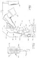
- the adjustable pedal apparatus 10 of the invention is illustrated in the drawings in association with a motor vehicle including a floor pan 11, a dash panel or fire wall 12, an instrument panel 13, and an operator's seat 14.
- Adjustable pedal apparatus 10 broadly considered, includes a pedal arm 15, a pedal pad 16, and an adjuster mechanism 18.
- Pedal arm 15 is pivotally mounted to the vehicle at 20 via a bracket 22 secured to the fire wall of the vehicle at a location intermediate upper end 15a of the pedal arm and lower end 15b of the pedal arm.
- a Bowden cable 24 is secured to the upper end 15a of the pedal arm and extends to an accelerator assembly (not shown) of the vehicle so that the accelerator assembly is controlled in response to pivotal movement of the pedal arm about pivot point 20.
- Pedal pad 16 comprises a slightly arcuate pad portion 16a for coaction with the foot 30 of an operator 32 positioned on seat 14 and a mounting portion 16b secured to the underface of pad portion 16a.
- Mounting portion 16b has a stepped configuration including an upper portion 16c and a lower portion 16d.
- Adjuster mechanism 18 includes an extensible module 34 and drive means 35.
- Module 34 includes a housing 36 secured to the lower end 15b of the pedal arm, an upper screw jack 38, and a lower screw jack 40.
- Housing 36 has a stepped rear face 36a having a configuration corresponding generally to the stepped configuration of pedal pad mounting portion 16b.
- stepped rear face 36a defines an upper face portion 36b a lower face portion 36c.
- Rear face portion 36c is stepped rearwardly with respect to rear face portion 36b to an extent corresponding to the extent to which the upper and lower portions 16b/16c of the mounting portion of the pedal pad are stepped with respect to each other.
- Housing 36 defines an upper cylindrical cavity 36d opening at 36e in rear face portion 36b and a lower cylindrical cavity 36f opening at 36g in rear face portion 36c.
- Lower cavity 36f is stepped rearwardly from upper cavity 36d by an amount commensurate with the rearward spacing of face portion 36c from face portion 36b.
- Upper screw jack 38 comprises a plurality of cylindrical members which are telescopically arranged one within the other.
- screw jack 38 includes a base member 42 of annular cylindrical configuration; a large screw member 44 of annular cylindrical configuration; an intermediate screw member 46c of annular cylindrical configuration; and a small or free end screw member 48 of solid cylindrical configuration.
- Base member 42 is mounted for rotation in cavity 36d and includes a gear portion 42a having an inner diameter defining an annular threaded portion 42b; large screw member 44 is sized to pass through opening 36e and includes an exterior thread 44a coacting with thread 42b, a forward outer flange portion 44b having an exterior diameter corresponding generally to the interior diameter of base member 42, and a rear inwardly extending flange portion 44c defining a screw thread 44d.
- Intermediate screw member 46 has an exterior thread 46a for coaction with screw thread 44d, a forward outer flange portion 46b having an exterior diameter corresponding generally to the interior diameter of screw member 44 and a rear inwardly extending flange portion 46c defining a screw thread 46d.
- Screw 48 defines an external thread 48a for coaction with screw thread 46d, a front flange 48b having an external diameter corresponding generally to the internal diameter of screw member 46, and a rearward pin portion 48c.
- Pin portion 48c is pivotally connected to upper pedal pad mounting portion 16c by a pivot pin 49.
- Lower screw jack 40 is generally similar to upper screw jack 38. Specifically, lower screw jack 40 includes a base member 50, a large screw member 52, an intermediate screw member 54, and a small or free end screw member 56.
- Base member 50 is mounted for rotation in cavity 36f and includes a forward gear portion 50a for meshing coaction with gear portion 42a of base member 42 via a passage 36h in the housing and a rear flange portion 50b defining a screw thread 50c.
- Large screw member 52 is sized to pass through opening 36g and includes an external thread 52a for threaded coaction with screw thread 50c, a forward outer flange 52b having an external diameter corresponding generally to the internal diameter of base member 50, and a rear inward flange 52c defining a screw thread 52d.
- Intermediate screw member 54 has an external thread 54a for coaction with screw thread 52d, a forward outer flange 52b having an external diameter corresponding generally to the internal diameter of screw member 52, and a rear inward flange 54c defining a screw thread 54d.
- Small or free end screw member 56 has an external thread 56a for coaction with screw thread 54d, a forward flange 56b having an external diameter corresponding generally to the internal diameter of screw member 54, and a rearward pin portion 56c.
- Pin portion 56c is pivotally connected to lower pivot pad mounting portion 16d by a pivot pin 57.
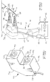
- Drive means 35 includes an electric motor 58 secured, for example, to fire wall 12; a Bowden cable 60 driven by the motor and passing downwardly through a bore 36i in the extensible module housing; a transmission 62 driven by the cable, and an output shaft 64 driven by the transmission and centrally connected to the forward wall 42c of the base member 42 of upper screw jack 38.
- Transmission 62 comprises a worm 66 secured to the free lower end of cable 60 driving a worm gear 68 fixedly and centrally secured to output shaft 64.
- Motor 58 is controlled via a circuit 70 associated with the vehicle battery 72 and includes, for example, a toggle switch 74 mounted in instrument panel 13 and operative in response to toggling movement by the vehicle operator to energize motor 58 in forward and rearward directions.
- a toggle switch 74 mounted in instrument panel 13 and operative in response to toggling movement by the vehicle operator to energize motor 58 in forward and rearward directions.
- pedal arm 15 is pivoted about pivot pin 20 to move Bowden cable 24 and selectively control the accelerator assembly of the vehicle.
- the idle position of the pedal assembly is seen in solid lines in Figure 2 and the maximum acceleration position is seen in dash lines in Figure 2.
- the angled cut-away portion 36j of the front face of the extensible module housing provides clearance with the lower angled portion 12a of the vehicle fire wall to facilitate the desired amount of pivotal movement of the pedal assembly between idle and maximum acceleration positions.
- the pedal apparatus is seen in Figure 1 in its totally retracted position to accommodate drivers of relatively large stature and is seen in Figure 2 in its maximum extended position to accommodate drivers of relatively short stature.
- the selected or desired position of extension of the pedal assembly is chosen by the operator and specifically is determined by operator actuation of switch 74 to selectively energize motor 58.
- switch 74 is actuated to energize motor 58 to drive cable 60 and transmission 62 to rotate the base member 42 of the upper jack 38 and, via gears 42a and 50a, the base member 50 of lower screw jack 40.
- Base members 42 and 50 thus rotate in counter rotating directions, and large screw members 44/52 move forwardly within base members 42/50 via the threaded coaction of screws 42b/44a and 50c/52a until outer flange portion 44b/52b encounters the front wall of the respective base member whereafter the sections 44/52 rotate with the base members 42/50.
- the linear length of the various screw elements of the lower jack 40 are made commensurately larger than the linear lengths of the corresponding screw members of the upper jack 38 to allow the further linear extension of the lower screw jack as compared to the upper screw jack.
- the pin 57 carried on the free end of the pin portion 56c of the lower screw jack is received in an arcuate slot 16e in the lower portion 16b of the mounting portion of the pedal pad to allow the upward pivotal movement of the pedal pad as the pedal pad is moved rearwardly to accommodate shorter drivers.
- the adjustable pedal assembly of the invention will be seen to provide many important advantages. Specifically, the modular concept allows one size of extensible module to be utilized in virtually all vehicular applications irrespective of extreme variations in dimensional and packaging requirements of the various vehicle applications. This in turn allows an extensible module according to the invention to be designed and tested and thereafter provided to the industry, without further design or testing, in satisfaction of virtually all vehicular applications. The resulting economies of scale significantly reduce the cost of the total package.
- the invention design also provides an extremely compact overall pedal assembly package allowing the invention pedal assembly to be utilized in even the most crowded of the under-instrument panel environments encountered in present day vehicles.
Abstract
Description
Claims (20)
- An adjustable pedal apparatus for a motor vehicle comprising:a pedal arm having a free end;means mounting the pedal arm for movement relative to the vehicle;means operative in response to movement of the pedal arm relative to the vehicle to control an associated device of the vehicle;a pedal pad carried on the free end of the pedal arm; andadjuster means operative to selectively adjust the position of the pedal pad relative to the free end of the pedal arm.
- An adjustable pedal assembly according to claim 1 wherein the adjuster means comprises a screw jack mounted on the free end of the pedal arm and engaging the pedal pad.
- An adjustable pedal assembly according to claim 1 wherein the adjuster means are operative to adjust both the distance of the pedal pad from the free end of the pedal arm and the angle of the pedal pad relative to the free end of the pedal arm.
- An adjustable pedal assembly according to claim 3 wherein the adjuster means comprises:upper and lower extensible devices carried on the free end of the pedal arm and engaging upper and lower regions on the pedal pad; anddrive means operative to extend the extensible devices by differential amounts whereby to tilt the pedal pad in response to extension of the extensible devices.
- An adjustable pedal assembly according to claim 4 wherein:each extensible device comprises a screw jack including a rotary drive member;the drive means are operative to rotate the drive members of the upper and lower screw jacks at the same speed; andthe lower screw jack employs a coarser thread than the upper screw jack so that, for a given number of revolutions of the drive members, the lower jack extends further than the upper screw jack whereby to tilt the pedal pad upwardly as the pad moves away from the free end of the pedal arm.
- An adjustable pedal assembly according to claim 1 wherein:the pedal arm is pivotally mounted on the vehicle at a pivot point and the free end of the arm comprises a lower end of the pedal arm;the adjuster means includes an extensible device on the lower end of the pedal arm positioned between the pedal arm and the pedal pad and drive means operative to extend the extensible device and adjust the position of the pedal pad relative to the lower end of the pedal arm.
- An adjustable pedal assembly according to claim 6 wherein the drive means includes a drive cable and transmission means operative in response to rotation of the cable to extend the extensible device.
- An adjustable pedal assembly according to claim 7 wherein:the extensible device comprises a screw jack including a rotatable base member and telescopic members positioned telescopically within the base member and extensible relative to the base member in response to rotation of the base member; andthe transmission means is operative in response to rotation of the cable to rotate the base member of the screw jack to thereby extend the telescopic members.
- An adjustable pedal assembly according to claim 8 wherein:the screw jack comprises an upper screw jack;the adjuster means further includes a lower screw jack positioned on the lower end of the pedal arm below the upper screw jack and including a rotatable base member and telescopic members positioned telescopically within the base member and extensible relative to the base member in response to rotation of the base member; andthe transmission means is operative in response to rotation of the cable to simultaneously rotate the base members of the upper and lower screw jacks to thereby extend the telescopic members of the upper and lower screw jacks.
- An adjustable pedal assembly according to claim 9 wherein the lower screw jack employs a coarser drive thread than the upper screw jack so that the lower screw jack extends further in response to a given number of rotations of the base members whereby to tilt the pedal pad relative to the pedal arm as the pedal pad moves away from the pedal arm.
- An adjustable vehicle pedal assembly including a pedal arm having a lower end, means mounting the pedal arm for pivotal movement relative to the vehicle, means operative in response to pivotal movement of the pedal arm relative to the vehicle to control an associated device of the vehicle, a pedal pad carried on the lower end of the pedal arm, and adjuster means operative to adjust the position of the pedal assembly relative to an operator seated on a driver's seat of the vehicle, characterized in that:the adjuster means comprises means operative to adjust the position of the pedal pad relative to the pedal arm.
- An adjustable pedal assembly according to claim 11 wherein the adjuster means includes an extensible device on the lower end of the pedal arm positioned between the pedal arm and the pedal pad and drive means operative to extend the extensible device and adjust the position of the pedal pad relative to the lower end of the pedal arm.
- An adjustable pedal assembly according to claim 12 wherein the drive means includes a drive cable and transmission means operative in response to rotation of the cable to extend the extensible device.
- An adjustable pedal assembly according to claim 13 wherein:the extensible device comprises a screw jack including a rotatable base member and telescopic members positioned telescopically within the base member and extensible relative to the base member in response to rotation of the base member; andthe transmission means is operative in response to rotation of the cable to rotate the base member of the screw jack to thereby extend the telescopic members.
- An adjustable pedal assembly according to claim 14 wherein:the screw jack comprises an upper screw jack;the adjuster means further includes a lower screw jack positioned on the lower end of the pedal arm below the upper screw jack and including a rotatable base member and telescopic members positioned telescopically within the base member and extensible relative to the base member in response to rotation of the base member; andthe transmission means is operative in response to rotation of the cable to simultaneously rotate the base members of the upper and lower screw jacks to thereby extend the telescopic members of the upper and lower screw jacks.
- An adjustable pedal assembly according to claim 15 wherein the lower screw jack employs a coarser drive thread than the upper screw jack so that the lower screw jack extends further in response to a given number of rotations of the base members whereby to tilt the pedal pad relative to the pedal arm as the pedal pad moves away from the pedal arm.
- An adjustable pedal assembly for a motor vehicle comprising:a pedal arm including a free lower end and means for pivotally mounting the arm on the vehicle;a pedal pad;an extensible module mounted on the lower end of the pedal arm and carrying the pedal pad; anddrive means operative to extend the extensible module and adjust the distance of the pedal pad from the lower end of the pedal arm.
- An adjustable pedal assembly according to claim 17 wherein:the extensible module comprises a housing fixedly secured to the lower end of the pedal arm and an extension device mounted on the housing and having a free extendible end; andthe pedal pad is mounted on the extendible end of the extension device.
- An adjustable pedal assembly according to claim 18 wherein the extendible device comprises a screw jack.
- An adjustable pedal assembly according to claim 18 wherein:the screw jack is an upper screw jack; andthe apparatus further includes a lower screw jack positioned on the housing below the upper screw jack and having a free end connected to the pedal pad below the connection of the free end of the upper screw jack to the pedal pad.
Applications Claiming Priority (2)
| Application Number | Priority Date | Filing Date | Title |
|---|---|---|---|
| US847617 | 1997-04-28 | ||
| US08/847,617 US5884532A (en) | 1997-04-28 | 1997-04-28 | Adjustable pedal apparatus |
Publications (2)
| Publication Number | Publication Date |
|---|---|
| EP0875812A2 true EP0875812A2 (en) | 1998-11-04 |
| EP0875812A3 EP0875812A3 (en) | 2002-01-30 |
Family
ID=25301067
Family Applications (1)
| Application Number | Title | Priority Date | Filing Date |
|---|---|---|---|
| EP98201267A Withdrawn EP0875812A3 (en) | 1997-04-28 | 1998-04-20 | Adjustable pedal apparatus |
Country Status (4)
| Country | Link |
|---|---|
| US (1) | US5884532A (en) |
| EP (1) | EP0875812A3 (en) |
| JP (1) | JPH10320065A (en) |
| CA (1) | CA2236013C (en) |
Cited By (2)
| Publication number | Priority date | Publication date | Assignee | Title |
|---|---|---|---|---|
| ES2182634A1 (en) * | 2000-05-12 | 2003-03-01 | Batz S Coop | Vehicle pedal position regulator |
| CN109094537A (en) * | 2018-08-24 | 2018-12-28 | 重庆长安汽车股份有限公司 | A kind of anti-intrusion brake pedal structure |
Families Citing this family (28)
| Publication number | Priority date | Publication date | Assignee | Title |
|---|---|---|---|---|
| US6189409B1 (en) * | 1999-01-11 | 2001-02-20 | Daimlerchrysler Corporation | Adjustable pedal system |
| US6212970B1 (en) | 1999-08-24 | 2001-04-10 | Teleflex Incorporated | Pedal assembly with adjustable pad |
| US6345550B1 (en) | 1999-10-15 | 2002-02-12 | Teleflex Incorporated | Guide for adjustable pad on pedal arm |
| DE10014531A1 (en) * | 2000-01-27 | 2001-08-09 | United Parts Fhs Automobil Sys | Adjustable pedal for fitting in motor vehicles and equipment has a pedal tread, a pedal arm with devices for holding connections for operating pull wires and a mounting on a pedal frame with several inter-movable parts. |
| JP4651898B2 (en) | 2000-04-07 | 2011-03-16 | アトマ インターナショナル コーポレイション | Adjustable pedal assembly for automobiles |
| DE10017531C2 (en) * | 2000-04-10 | 2002-03-07 | Edscha Ag | Adjustable pedal works |
| US6321617B1 (en) | 2000-06-08 | 2001-11-27 | Jeffrey Schwyn | Adjustable pedal assembly |
| US6389927B1 (en) * | 2000-07-12 | 2002-05-21 | Ksr International, Inc. | Adjustable control vehicle pedal |
| WO2003023543A1 (en) * | 2000-07-12 | 2003-03-20 | Ksr Industrial Corporation | Adjustable control vehicle pedal |
| US6609438B1 (en) | 2000-08-18 | 2003-08-26 | Dura Global Technologies, Inc | Electric adjustable pedal system with two-piece upper arm |
| US6364047B1 (en) | 2000-09-27 | 2002-04-02 | Teleflex Incorporated | Adjustable pedal assembly—floating floor |
| US6732035B2 (en) | 2000-10-11 | 2004-05-04 | Daimlerchrysler Corporation | Adjustable pedal assembly for a motor vehicle with a safety feature |
| US6739212B2 (en) | 2000-12-22 | 2004-05-25 | Dura Global Technologies, Inc. | Adjustable pedal controller with obstruction detection |
| US6516683B2 (en) | 2000-12-29 | 2003-02-11 | Dura Global Technologies, Inc. | Electric adjustable pedal system with mechanical active lock-up |
| US6962094B2 (en) | 2001-01-24 | 2005-11-08 | Orscheln Products Llc | Adjustable pedal assembly |
| US7114411B2 (en) * | 2001-05-09 | 2006-10-03 | Ksr Industrial Corporation | Pedal adjuster |
| US6862950B2 (en) | 2001-11-02 | 2005-03-08 | Ksr Industrial Corporation | Adjustable pedal assembly |
| US6609436B2 (en) | 2002-01-03 | 2003-08-26 | James M. Laws | Vehicle brake pedal apparatus |
| CA2545289C (en) * | 2003-11-13 | 2012-08-07 | Magna Closures Inc. | Moveable control pedal assembly |
| JP5044104B2 (en) * | 2005-04-11 | 2012-10-10 | 富士重工業株式会社 | Shift control device for automatic transmission |
| US20080053265A1 (en) * | 2006-09-01 | 2008-03-06 | Bannon Sean A | Pedal assembly |
| US20080229872A1 (en) * | 2007-03-21 | 2008-09-25 | Agco Corporation | Adjustable pedal assembly |
| US8069750B2 (en) | 2007-08-09 | 2011-12-06 | Ksr Technologies Co. | Compact pedal assembly with improved noise control |
| US8230836B2 (en) * | 2009-07-27 | 2012-07-31 | Kamen George Kamenov | Multi-cylinder reciprocating rotary engine |
| US9764464B2 (en) * | 2011-08-03 | 2017-09-19 | The Boeing Company | Robot including telescopic assemblies for positioning an end effector |
| DE102014220466A1 (en) * | 2014-10-09 | 2016-04-14 | Robert Bosch Gmbh | Accelerator pedal with haptic signaling |
| US10988097B2 (en) * | 2019-04-03 | 2021-04-27 | GM Global Technology Operations LLC | Retractable pedal assembly for a vehicle |
| US10889226B1 (en) | 2019-10-14 | 2021-01-12 | Ford Global Technologies, Llc | Vehicle pedal cover |
Citations (6)
| Publication number | Priority date | Publication date | Assignee | Title |
|---|---|---|---|---|
| US1425413A (en) * | 1921-05-07 | 1922-08-08 | Victor W Page | Adjustable foot pedal |
| US1484847A (en) * | 1919-01-03 | 1924-02-26 | Francis B Stuart | Extension pedal |
| GB813923A (en) * | 1956-04-25 | 1959-05-27 | Standard Pressed Steel Co | Improvements in or relating to control pedals for vehicles |
| US3626785A (en) * | 1970-08-21 | 1971-12-14 | John W Ross | Universal pedal extension |
| EP0653694A1 (en) * | 1993-11-12 | 1995-05-17 | Young-Ryeol Song | Pedals for automobiles |
| JPH07271464A (en) * | 1994-03-30 | 1995-10-20 | Toyota Tekko Kk | Back and forth adjustable operation pedal device |
Family Cites Families (8)
| Publication number | Priority date | Publication date | Assignee | Title |
|---|---|---|---|---|
| US3643525A (en) * | 1970-05-26 | 1972-02-22 | Gen Motors Corp | Adjustable control pedals for vehicles |
| DE3427416C2 (en) * | 1984-07-25 | 1986-06-12 | Messerschmitt-Bölkow-Blohm GmbH, 8012 Ottobrunn | Actuating device with an operating means to be actuated by foot angle movements |
| US5078024A (en) * | 1986-08-18 | 1992-01-07 | Comfort Pedals Inc. | Control pedal apparatus for a motor vehicle |
| US5233882A (en) * | 1990-07-12 | 1993-08-10 | General Motors Corporation | Remote control lever module |
| US5408899A (en) * | 1993-06-14 | 1995-04-25 | Brecom Subsidiary Corporation No. 1 | Foot pedal devices for controlling engines |
| US5460061A (en) * | 1993-09-17 | 1995-10-24 | Comfort Pedals, Inc. | Adjustable control pedal apparatus |
| US5632183A (en) * | 1995-08-09 | 1997-05-27 | Comfort Pedals, Inc. | Adjustable pedal assembly |
| US5722302A (en) * | 1995-08-09 | 1998-03-03 | Teleflex, Inc. | Adjustable pedal assembly |
-
1997
- 1997-04-28 US US08/847,617 patent/US5884532A/en not_active Expired - Fee Related
-
1998
- 1998-04-20 EP EP98201267A patent/EP0875812A3/en not_active Withdrawn
- 1998-04-27 CA CA002236013A patent/CA2236013C/en not_active Expired - Fee Related
- 1998-04-28 JP JP10119251A patent/JPH10320065A/en active Pending
Patent Citations (6)
| Publication number | Priority date | Publication date | Assignee | Title |
|---|---|---|---|---|
| US1484847A (en) * | 1919-01-03 | 1924-02-26 | Francis B Stuart | Extension pedal |
| US1425413A (en) * | 1921-05-07 | 1922-08-08 | Victor W Page | Adjustable foot pedal |
| GB813923A (en) * | 1956-04-25 | 1959-05-27 | Standard Pressed Steel Co | Improvements in or relating to control pedals for vehicles |
| US3626785A (en) * | 1970-08-21 | 1971-12-14 | John W Ross | Universal pedal extension |
| EP0653694A1 (en) * | 1993-11-12 | 1995-05-17 | Young-Ryeol Song | Pedals for automobiles |
| JPH07271464A (en) * | 1994-03-30 | 1995-10-20 | Toyota Tekko Kk | Back and forth adjustable operation pedal device |
Non-Patent Citations (1)
| Title |
|---|
| PATENT ABSTRACTS OF JAPAN vol. 1996, no. 02, 29 February 1996 (1996-02-29) & JP 07 271464 A (TOYOTA TEKKO KK), 20 October 1995 (1995-10-20) * |
Cited By (2)
| Publication number | Priority date | Publication date | Assignee | Title |
|---|---|---|---|---|
| ES2182634A1 (en) * | 2000-05-12 | 2003-03-01 | Batz S Coop | Vehicle pedal position regulator |
| CN109094537A (en) * | 2018-08-24 | 2018-12-28 | 重庆长安汽车股份有限公司 | A kind of anti-intrusion brake pedal structure |
Also Published As
| Publication number | Publication date |
|---|---|
| CA2236013A1 (en) | 1998-10-28 |
| JPH10320065A (en) | 1998-12-04 |
| EP0875812A3 (en) | 2002-01-30 |
| CA2236013C (en) | 2001-08-21 |
| US5884532A (en) | 1999-03-23 |
Similar Documents
| Publication | Publication Date | Title |
|---|---|---|
| US5884532A (en) | Adjustable pedal apparatus | |
| US5890399A (en) | Adjustable pedal assembly | |
| US5240284A (en) | Steering column assembly with horizontal position adjustment mechanism | |
| US6151984A (en) | Adjustable pedal assembly | |
| US7159904B2 (en) | Steering column for a motor vehicle | |
| US5086663A (en) | Adjustable pedal | |
| US6289761B1 (en) | Automatic adjustable brake, clutch and accelerator pedals | |
| US7407190B2 (en) | Steering column assembly | |
| CN108327649B (en) | Supporting device of vehicle-mounted display terminal and vehicle | |
| US6389927B1 (en) | Adjustable control vehicle pedal | |
| US6314831B2 (en) | Adjustable pedal-parallel screw and rod | |
| KR20030029989A (en) | Pedal mounting structure | |
| US20020023516A1 (en) | Adjustable foot-operated control mechanism | |
| EP1280034B1 (en) | Device for adjusting the position of a pedal | |
| US6598495B2 (en) | Plastic adjustable accelerator pedal with internal drive mechanism | |
| JP4874517B2 (en) | Adjustable vehicle pedal | |
| EP0402133A1 (en) | Steering column assembly with horizontal position adjustment mechanism | |
| MXPA98003293A (en) | Regula pedal apparatus | |
| AU2001293238A1 (en) | Adjustable control vehicle pedal | |
| KR100254560B1 (en) | Room mirror for an automobile | |
| KR100372460B1 (en) | Pedal control apparatus for an automobile | |
| EP1385077A1 (en) | Plastic adjustable accelerator pedal with internal drive mechanism | |
| JPS6111836A (en) | Pedal device of automoble | |
| KR19980032902U (en) | Position adjustable pedal device | |
| JPH0712828B2 (en) | Horizontal slide device for steering column |
Legal Events
| Date | Code | Title | Description |
|---|---|---|---|
| PUAI | Public reference made under article 153(3) epc to a published international application that has entered the european phase |
Free format text: ORIGINAL CODE: 0009012 |
|
| AK | Designated contracting states |
Kind code of ref document: A2 Designated state(s): AT BE CH CY DE DK ES FI FR GB GR IE IT LI LU MC NL PT SE Kind code of ref document: A2 Designated state(s): DE ES FR GB IT |
|
| AX | Request for extension of the european patent |
Free format text: AL;LT;LV;MK;RO;SI |
|
| PUAL | Search report despatched |
Free format text: ORIGINAL CODE: 0009013 |
|
| AK | Designated contracting states |
Kind code of ref document: A3 Designated state(s): AT BE CH CY DE DK ES FI FR GB GR IE IT LI LU MC NL PT SE |
|
| AX | Request for extension of the european patent |
Free format text: AL;LT;LV;MK;RO;SI |
|
| 17P | Request for examination filed |
Effective date: 20020215 |
|
| AKX | Designation fees paid |
Free format text: DE ES FR GB IT |
|
| STAA | Information on the status of an ep patent application or granted ep patent |
Free format text: STATUS: THE APPLICATION IS DEEMED TO BE WITHDRAWN |
|
| 18D | Application deemed to be withdrawn |
Effective date: 20051101 |