EP0909689A2 - Antiskid/autobrake control system with low-speed brake release to reduce gear walk - Google Patents
Antiskid/autobrake control system with low-speed brake release to reduce gear walk Download PDFInfo
- Publication number
- EP0909689A2 EP0909689A2 EP98203001A EP98203001A EP0909689A2 EP 0909689 A2 EP0909689 A2 EP 0909689A2 EP 98203001 A EP98203001 A EP 98203001A EP 98203001 A EP98203001 A EP 98203001A EP 0909689 A2 EP0909689 A2 EP 0909689A2
- Authority
- EP
- European Patent Office
- Prior art keywords
- low
- speed
- antiskid
- brake release
- brake
- Prior art date
- Legal status (The legal status is an assumption and is not a legal conclusion. Google has not performed a legal analysis and makes no representation as to the accuracy of the status listed.)
- Granted
Links
- 238000010586 diagram Methods 0.000 description 6
- 230000004048 modification Effects 0.000 description 3
- 230000000694 effects Effects 0.000 description 2
- 230000000994 depressogenic effect Effects 0.000 description 1
- 230000002401 inhibitory effect Effects 0.000 description 1
- 230000000977 initiatory effect Effects 0.000 description 1
- 238000002955 isolation Methods 0.000 description 1
- 238000012986 modification Methods 0.000 description 1
- 230000002028 premature Effects 0.000 description 1
Images


Classifications
-
- B—PERFORMING OPERATIONS; TRANSPORTING
- B60—VEHICLES IN GENERAL
- B60T—VEHICLE BRAKE CONTROL SYSTEMS OR PARTS THEREOF; BRAKE CONTROL SYSTEMS OR PARTS THEREOF, IN GENERAL; ARRANGEMENT OF BRAKING ELEMENTS ON VEHICLES IN GENERAL; PORTABLE DEVICES FOR PREVENTING UNWANTED MOVEMENT OF VEHICLES; VEHICLE MODIFICATIONS TO FACILITATE COOLING OF BRAKES
- B60T8/00—Arrangements for adjusting wheel-braking force to meet varying vehicular or ground-surface conditions, e.g. limiting or varying distribution of braking force
- B60T8/17—Using electrical or electronic regulation means to control braking
- B60T8/176—Brake regulation specially adapted to prevent excessive wheel slip during vehicle deceleration, e.g. ABS
- B60T8/1761—Brake regulation specially adapted to prevent excessive wheel slip during vehicle deceleration, e.g. ABS responsive to wheel or brake dynamics, e.g. wheel slip, wheel acceleration or rate of change of brake fluid pressure
- B60T8/17616—Microprocessor-based systems
-
- B—PERFORMING OPERATIONS; TRANSPORTING
- B60—VEHICLES IN GENERAL
- B60T—VEHICLE BRAKE CONTROL SYSTEMS OR PARTS THEREOF; BRAKE CONTROL SYSTEMS OR PARTS THEREOF, IN GENERAL; ARRANGEMENT OF BRAKING ELEMENTS ON VEHICLES IN GENERAL; PORTABLE DEVICES FOR PREVENTING UNWANTED MOVEMENT OF VEHICLES; VEHICLE MODIFICATIONS TO FACILITATE COOLING OF BRAKES
- B60T8/00—Arrangements for adjusting wheel-braking force to meet varying vehicular or ground-surface conditions, e.g. limiting or varying distribution of braking force
- B60T8/32—Arrangements for adjusting wheel-braking force to meet varying vehicular or ground-surface conditions, e.g. limiting or varying distribution of braking force responsive to a speed condition, e.g. acceleration or deceleration
- B60T8/321—Arrangements for adjusting wheel-braking force to meet varying vehicular or ground-surface conditions, e.g. limiting or varying distribution of braking force responsive to a speed condition, e.g. acceleration or deceleration deceleration
- B60T8/325—Systems specially adapted for aircraft
-
- Y—GENERAL TAGGING OF NEW TECHNOLOGICAL DEVELOPMENTS; GENERAL TAGGING OF CROSS-SECTIONAL TECHNOLOGIES SPANNING OVER SEVERAL SECTIONS OF THE IPC; TECHNICAL SUBJECTS COVERED BY FORMER USPC CROSS-REFERENCE ART COLLECTIONS [XRACs] AND DIGESTS
- Y10—TECHNICAL SUBJECTS COVERED BY FORMER USPC
- Y10S—TECHNICAL SUBJECTS COVERED BY FORMER USPC CROSS-REFERENCE ART COLLECTIONS [XRACs] AND DIGESTS
- Y10S303/00—Fluid-pressure and analogous brake systems
- Y10S303/08—Antichatter
Definitions
- This invention relates to brake systems and, more particularly, to brake control systems.
- the brake systems of modern commercial airplanes are hydraulic and include electrically operated brake-metering valves, autobrake shuttle valves, and antiskid valves.
- the valves are controlled by an antiskid/autobrake control unit that produces and sends control signals to the valves of the brake system in accordance with a software program that receives inputs from various sensors and control sources. Pilot instructions produced by the operation of brake pedals or an autobrake setting control the operation of the brake metering valves and the antiskid valves in a manner designed to decelerate an airplane in a smooth manner.
- the brake metering valves control brake pressure and the antiskid valves control the release of brake pressure in a manner designed to minimize wheel skidding.
- the present invention is directed to modifying a brake system in a manner that substantially reduces gear walk and, thus, the shudder caused by gear walk.
- the control system that controls the operation of a braking system applies a brake release signal to the antiskid valves of the brake system associated with some but not all of the wheels of an airplane.
- the brake release signal prevents brake shudder caused by gear walk by requiring that greater brake meter pressure be applied to the remaining wheels of the airplane in order to maintain the same deceleration.
- the increased brake meter pressure attenuates the gear walk of the remaining wheels.
- the brake control system obtains a measured wheelspeed value for each of the some but not all of the wheels and calculates a reference wheelspeed value based on the measured wheelspeed value. Tests are made to determine if the reference wheelspeed value is below some predetermined magnitude, e.g., 15 knots, and if the airplane ground speed value is below some predetermined magnitude, e.g., 50 knots. If the tests are passed, a low-speed brake release current to be applied to the antiskid valves of the airplane's braking system is determined.
- some predetermined magnitude e.g. 15 knots
- some predetermined magnitude e.g. 50 knots
- the low-speed brake release current ramps on as the airplane slows to a stop.
- a test is made to determine if a valid wheelspeed value has been detected for a predetermined period of time, e.g., 0.5 seconds. If not, the low-speed brake release current is reduced to zero.
- a test is made to determine if the low-speed brake release current is greater than the antiskid control current, which is derived from another source that does not form part of this invention. If the low-speed brake release current is greater than the antiskid control current, the low-speed release current is applied to the antiskid valves of the brake system. If the low-speed release current is not greater than the antiskid control current, the antiskid control current is applied to the antiskid valves of the brake system.
- the invention attenuates the shudder caused by gear walk in a relatively uncomplicated manner. Releasing some of the brakes at low speeds makes it necessary for greater brake pressure to be applied to the remaining brakes in order to maintain the same deceleration. The increased brake metered pressure on the remaining brakes attenuates the gear walk of the landing gear.
- FIGURE 1 is a block diagram of a brake system for a contemporary commercial airplane such as the Boeing 737.
- the brake system includes two sets of brake pedals.
- the captain's brake pedals 21a and 21b are connected to the first officer's brake pedals 23a and 23b by a bus bar and connecting linkage 25a and 25b.
- Cables 27a and 27b located on the left and right sides of the airplane, connect the pedals 21a, 21b, 23a and 23b to brake-metering valve modules 29a and 29b located in each wheelwell.
- Each brake-metering module includes a normal brake-metering valve 31 and an alternate brake-metering valve 33.
- the normal brake-metering valves 31 form part of a normal brake system and the alternate brake-metering valves 33 form part of an alternate brake system.
- the normal brake system is used under normal conditions and the alternate brake system is used when the normal brake system fails.
- a parking brake lever 35 latches the brakes on when both brake pedals are fully depressed by either the captain or the first officer.
- the normal brake system is powered by a normal hydraulic system designated system B.
- the alternate brake system is powered by an alternate hydraulic system designated system A.
- the alternate brake system is automatically selected by an automatic brake selector valve 39 when hydraulic power is lost by the normal hydraulic system, i.e., system B.
- An accumulator 41 in the normal brake system is automatically selected when both normal and alternate brake hydraulic power is lost.
- An accumulator isolation valve 43 isolates the accumulator 41 from the remainder of the system.
- the normal and alternate brake-metering valves 31 and 33 control the amount of hydraulic system pressure applied to normal or alternate antiskid valve modules 45 and 47, respectively.
- the autobrake shuttle valves 51 are controlled by an autobrake valve module 49, which, in turn, is controlled by an antiskid/antibrake control unit 55.
- the normal antiskid valve modules 45 receive either normal brake metered pressure from the normal brake metering valves 31 or autobrake pressure from the autobrake valve module 49 and regulate the pressure applied by the brakes of the airplane wheels 53.
- the alternate antiskid valve modules 47 receive alternate brake pressure from the alternate brake metering valves 33 and regulate pressure to the brakes when, as noted above, the normal brake system fails.
- An antiskid/autobrake control unit 55 sends electrical control signals to the antiskid valve modules 45 and the alternate antiskid valve modules 47 to control braking under skid conditions.
- the antiskid/autobrake control unit also sends electrical control signals to the autobrake valve module that causes brake pressure to be metered in a manner that maintains a preset deceleration.
- Wheelspeed transducers mounted in the axles of the wheels 53 produce the wheelspeed signals that are used by the software of the antiskid/autobrake control unit 55 to create the desired electrical control signals.
- the antiskid system controls braking pressure in a manner that achieves maximum effectiveness in both automatic and manual brake operations under all runway conditions. In essence, the control signals release the brakes when a wheel skid is detected in order to reduce skidding.
- the antiskid/autobrake control unit receives input from a transducer associated with each of the four wheels shown in FIGURE 1.
- the antiskid/autobrake control unit 55 uses these inputs to control the amount of brake pressure applied by the normal and alternate antiskid valve modules to the wheels via the antiskid shuttle valve modules 57.
- the antiskid system allows maximum braking without locking the wheels and provides hydroplane and touchdown protection.
- the autobrake system provides automatic braking control by applying hydraulic brake pressure on landing or upon initiation of a refuse takeoff (RTO).
- the system operates with the normal antiskid system and at least one inertial reference system--normally the Airplane Data Inertial Reference Unit (ADIRU).
- the ADIRU is independent of the antiskid/autobrake control unit.
- the ADIRU uses accelerometers to determine airplane ground speed.
- the autobrake system brings an airplane to a complete stop unless it is disarmed by the pilot.
- An autobrake selector switch (not shown) has five landing settings. Deceleration can be changed during roll-out.
- the autobrake system regulates brake pressure to control the overall deceleration of the airplane. The amount of brake pressure commanded will vary, depending upon decelerating forces.
- maximum braking system pressure is applied to all wheels if both thrust levers are moved to idle during a takeoff roll.
- the autobrake selector switch returns to an off position at lift-off. In other airplanes the autobrake selector switch does not return to an off position at lift-off.
- FIGURE 1 It has been found that some brake systems of the type illustrated in FIGURE 1 can experience brake shudder when an airplane comes to a stop. Shudder is caused by landing gear structure moving fore and aft at a high frequency. This effect is commonly referred to as "gear walk.” As will be better understood from the following discussion, it has been found that releasing some of the brakes at low speed (e.g., two of the four brakes illustrated in FIGURE 1) will significantly reduce gear walk. The present invention accomplishes this result by modifying the software that operates the antiskid/autobrake control unit.
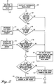
- FIGURE 2 illustrates the software modification.
- FIGURE 2 is a block diagram illustrating the software modification for each of the brakes to be released. The software that controls the unreleased brakes is not modified.
- the first step of the modification is to measure the wheelspeed value for the related wheel. This is accomplished by reading the output of the related wheelspeed transducer previously described in connection with FIGURE 1. See block 61.
- a reference wheelspeed valve is calculated based on the measured wheelspeed. Reference wheelspeed is the speed of an unbraked wheel and is calculated using a well-known algorithm.
- a test is made to determine if the reference wheelspeed value is less than a predetermined (X) numbers of knots. See block 65. In one actual embodiment of the invention, X was chosen to be 15 knots.
- the program cycles to block 67, where the low-speed release current is set to zero and the alternate antiskid valve driver is reactivated.
- the alternate antiskid valve driver operates the alternate antiskid valve modules 47, illustrated in FIGURE 1 and previously described, in the event the normal brake system fails.
- a test is made to determine if the ground speed of the airplane determined by the inertial reference system of the airplane, e.g., the ADIRU, is less than Y knots. See block 69. In one actual embodiment of the invention, Y was chosen to be 50 knots. If the calculated wheelspeed is not less than Y knots, the program cycles to block 67 where, as noted above, the low speed release current is set to zero and the alternate antiskid valve driver is reactivated.
- FIGURE 3 is a graph of release signal current versus reference wheelspeed.
- the release signal current fails between 0 to 25 milliamps (mA) in the example illustrated in FIGURE 3.
- the release signal is zero.
- no low-speed brake release current is produced.
- the current ramps from 0 to a maximum value of 25 mA.
- the release signal is at the maximum value, i.e., 25 mA.
- the low-speed brake release current ramps in the manner illustrated in FIGURE 3 in order to prevent an abrupt change in airplane deceleration when a brake is released.
- the graph illustrated in FIGURE 3 is stored as a table in the memory of the antiskid/autobrake control unit and is used in combination with a suitable interpolation algorithm to determine low-speed brake release current based on reference wheelspeed value.
- the alternate antiskid valve driver is inhibited. See block 73. Thereafter, a test is made to determine if a valid wheelspeed value has been detected in the previous Z number of seconds. See block 75. In one actual embodiment of the invention, Z is set equal to one-half second. If a valid wheel speed has not been detected in the previous Z seconds, the program cycles to block 67, wherein the low-speed release current is set to zero and the alternate antiskid valve driver is reactivated.
- the logic paths come together and a test is made to determine if the low-speed release current is greater than the antiskid control current. See block 77.
- the antiskid control current is determined by antiskid logic that does not form part of this invention. If the low-speed release current is not greater than the antiskid control current, the antiskid control current forms the output. See block 79. If the low-speed release current is greater than the antiskid control current, the low-speed release current forms the output. See block 81.
- the maximum low-speed brake release signal current was set at 25 milliamps because this takes advantage of multigain antiskid valve characteristics included in the brakes of the related aircraft--the Boeing 737-700.
- the multigain antiskid valve pressure versus current relationship is shown in FIGURE 4. At low metered pressures (less than 1,000 psi) where gear walk occurs, the 25 mA signal is sufficient to fully release a brake. In contrast, if a pilot meters 3,000 psi in a panic stop situation, a greater amount of pressure, e.g., 1,200 psi, will be applied to the brakes.
- the alternate antiskid valve drivers are inhibited. This prevents the low-speed release signal from affecting the alternate brake system. Instead of releasing only two of the four brakes on the airplane, the low-speed brake release current would cause all four brakes to be released if the alternate system were in operation. To prevent this, the alternate antiskid system is "turned off” by inhibiting the alternate antiskid valve drivers when a low-speed brake release current of suitable magnitude is to be produced.
- the low-speed brake release current is compared with an antiskid control current calculated by other software not illustrated in FIGURE 2 and which does not form part of this invention. Whichever signal is greater is supplied to the antiskid valve. This allows the antiskid control algorithm to override the low-speed brake release current if a tire is skidding.
- the invention provides a brake control system that reduces gear walk by releasing some of the brakes of an airplane during deceleration. Because gear walk is reduced, airplane shudder is reduced. As a result, passenger and pilot comfort is increased. In addition, the potential for structural fatigue is reduced.
Abstract
Description
- This invention relates to brake systems and, more particularly, to brake control systems.
- The brake systems of modern commercial airplanes are hydraulic and include electrically operated brake-metering valves, autobrake shuttle valves, and antiskid valves. The valves are controlled by an antiskid/autobrake control unit that produces and sends control signals to the valves of the brake system in accordance with a software program that receives inputs from various sensors and control sources. Pilot instructions produced by the operation of brake pedals or an autobrake setting control the operation of the brake metering valves and the antiskid valves in a manner designed to decelerate an airplane in a smooth manner. The brake metering valves control brake pressure and the antiskid valves control the release of brake pressure in a manner designed to minimize wheel skidding.
- It has been found that some airplanes experience brake shudder at low speeds. Brake shudder is caused by landing gear structure moving fore and aft at a high frequency. This effect, called "gear walk," is a dynamic instability between the landing gear structure and the brakes of the airplane. Gear walk causes the airplane to shudder to the extent that passengers and pilots find it objectionable. In addition to passengers and pilots finding gear walk objectionable, gear walk is also disadvantageous because it causes increased loads on landing gear structure, which may result in premature failure to due to fatigue.
- The present invention is directed to modifying a brake system in a manner that substantially reduces gear walk and, thus, the shudder caused by gear walk.
- In accordance with this invention, at low speeds, the control system that controls the operation of a braking system applies a brake release signal to the antiskid valves of the brake system associated with some but not all of the wheels of an airplane. The brake release signal prevents brake shudder caused by gear walk by requiring that greater brake meter pressure be applied to the remaining wheels of the airplane in order to maintain the same deceleration. The increased brake meter pressure attenuates the gear walk of the remaining wheels.
- In accordance with further aspects of this invention, the brake control system obtains a measured wheelspeed value for each of the some but not all of the wheels and calculates a reference wheelspeed value based on the measured wheelspeed value. Tests are made to determine if the reference wheelspeed value is below some predetermined magnitude, e.g., 15 knots, and if the airplane ground speed value is below some predetermined magnitude, e.g., 50 knots. If the tests are passed, a low-speed brake release current to be applied to the antiskid valves of the airplane's braking system is determined.
- In accordance with further aspects of this invention, in order to prevent an abrupt change in braking, the low-speed brake release current ramps on as the airplane slows to a stop.
- In accordance with still further aspects of this invention, a test is made to determine if a valid wheelspeed value has been detected for a predetermined period of time, e.g., 0.5 seconds. If not, the low-speed brake release current is reduced to zero.
- In accordance with yet still other aspects of this invention, a test is made to determine if the low-speed brake release current is greater than the antiskid control current, which is derived from another source that does not form part of this invention. If the low-speed brake release current is greater than the antiskid control current, the low-speed release current is applied to the antiskid valves of the brake system. If the low-speed release current is not greater than the antiskid control current, the antiskid control current is applied to the antiskid valves of the brake system.
- As will be readily appreciated from the foregoing description, the invention attenuates the shudder caused by gear walk in a relatively uncomplicated manner. Releasing some of the brakes at low speeds makes it necessary for greater brake pressure to be applied to the remaining brakes in order to maintain the same deceleration. The increased brake metered pressure on the remaining brakes attenuates the gear walk of the landing gear.
- The foregoing aspects and many of the attendant advantages of this invention will become more readily appreciated as the same becomes better understood by reference to the following detailed description, when taken in conjunction with the accompanying drawings, wherein:
- FIGURE 1 is a block diagram of an exemplary airplane brake system;
- FIGURE 2 is a functional block diagram of brake system software formed in accordance with the invention in a manner for attenuating gear walk;
- FIGURE 3 is a release signal versus reference wheelspeed diagram depicting the ramp off low-speed brake release current in accordance with this invention; and
- FIGURE 4 is a brake pressure versus current diagram for a multigain antiskid valve.
-
- FIGURE 1 is a block diagram of a brake system for a contemporary commercial airplane such as the Boeing 737. In order to provide full and differential braking capability, the brake system includes two sets of brake pedals. The captain's
brake pedals 21a and 21b are connected to the first officer'sbrake pedals 23a and 23b by a bus bar and connectinglinkage 25a and 25b. Cables 27a and 27b, located on the left and right sides of the airplane, connect thepedals metering valve modules 29a and 29b located in each wheelwell. Each brake-metering module includes a normal brake-metering valve 31 and an alternate brake-metering valve 33. The normal brake-metering valves 31 form part of a normal brake system and the alternate brake-metering valves 33 form part of an alternate brake system. The normal brake system is used under normal conditions and the alternate brake system is used when the normal brake system fails. A parking brake lever 35 latches the brakes on when both brake pedals are fully depressed by either the captain or the first officer. - The normal brake system is powered by a normal hydraulic system designated system B. The alternate brake system is powered by an alternate hydraulic system designated system A. The alternate brake system is automatically selected by an automatic
brake selector valve 39 when hydraulic power is lost by the normal hydraulic system, i.e., system B. Anaccumulator 41 in the normal brake system is automatically selected when both normal and alternate brake hydraulic power is lost. Anaccumulator isolation valve 43 isolates theaccumulator 41 from the remainder of the system. - The normal and alternate brake-
metering valves antiskid valve modules brake metering valves 31 and the normalantiskid valve modules 45 on the right and left sides of the airplane areautobrake shuttle valves 51. Theautobrake shuttle valves 51 are controlled by anautobrake valve module 49, which, in turn, is controlled by an antiskid/antibrake control unit 55. The normalantiskid valve modules 45 receive either normal brake metered pressure from the normalbrake metering valves 31 or autobrake pressure from theautobrake valve module 49 and regulate the pressure applied by the brakes of theairplane wheels 53. The alternateantiskid valve modules 47 receive alternate brake pressure from the alternatebrake metering valves 33 and regulate pressure to the brakes when, as noted above, the normal brake system fails. - An antiskid/
autobrake control unit 55 sends electrical control signals to theantiskid valve modules 45 and the alternateantiskid valve modules 47 to control braking under skid conditions. The antiskid/autobrake control unit also sends electrical control signals to the autobrake valve module that causes brake pressure to be metered in a manner that maintains a preset deceleration. Wheelspeed transducers mounted in the axles of thewheels 53 produce the wheelspeed signals that are used by the software of the antiskid/autobrake control unit 55 to create the desired electrical control signals. - The antiskid system controls braking pressure in a manner that achieves maximum effectiveness in both automatic and manual brake operations under all runway conditions. In essence, the control signals release the brakes when a wheel skid is detected in order to reduce skidding. The antiskid/autobrake control unit receives input from a transducer associated with each of the four wheels shown in FIGURE 1. The antiskid/
autobrake control unit 55 uses these inputs to control the amount of brake pressure applied by the normal and alternate antiskid valve modules to the wheels via the antiskidshuttle valve modules 57. The antiskid system allows maximum braking without locking the wheels and provides hydroplane and touchdown protection. - The autobrake system provides automatic braking control by applying hydraulic brake pressure on landing or upon initiation of a refuse takeoff (RTO). The system operates with the normal antiskid system and at least one inertial reference system--normally the Airplane Data Inertial Reference Unit (ADIRU). The ADIRU is independent of the antiskid/autobrake control unit. The ADIRU uses accelerometers to determine airplane ground speed. The autobrake system brings an airplane to a complete stop unless it is disarmed by the pilot.
- An autobrake selector switch (not shown) has five landing settings. Deceleration can be changed during roll-out. The autobrake system regulates brake pressure to control the overall deceleration of the airplane. The amount of brake pressure commanded will vary, depending upon decelerating forces. When the RTO position is selected before takeoff, maximum braking system pressure is applied to all wheels if both thrust levers are moved to idle during a takeoff roll. In some airplanes, during normal takeoff, the autobrake selector switch returns to an off position at lift-off. In other airplanes the autobrake selector switch does not return to an off position at lift-off.
- It has been found that some brake systems of the type illustrated in FIGURE 1 can experience brake shudder when an airplane comes to a stop. Shudder is caused by landing gear structure moving fore and aft at a high frequency. This effect is commonly referred to as "gear walk." As will be better understood from the following discussion, it has been found that releasing some of the brakes at low speed (e.g., two of the four brakes illustrated in FIGURE 1) will significantly reduce gear walk. The present invention accomplishes this result by modifying the software that operates the antiskid/autobrake control unit. FIGURE 2 illustrates the software modification.
- FIGURE 2 is a block diagram illustrating the software modification for each of the brakes to be released. The software that controls the unreleased brakes is not modified.
- As shown in FIGURE 2, the first step of the modification is to measure the wheelspeed value for the related wheel. This is accomplished by reading the output of the related wheelspeed transducer previously described in connection with FIGURE 1. See
block 61. Next, atblock 63, a reference wheelspeed valve is calculated based on the measured wheelspeed. Reference wheelspeed is the speed of an unbraked wheel and is calculated using a well-known algorithm. Next a test is made to determine if the reference wheelspeed value is less than a predetermined (X) numbers of knots. Seeblock 65. In one actual embodiment of the invention, X was chosen to be 15 knots. If the reference wheelspeed is not less than X knots, the program cycles to block 67, where the low-speed release current is set to zero and the alternate antiskid valve driver is reactivated. The alternate antiskid valve driver operates the alternateantiskid valve modules 47, illustrated in FIGURE 1 and previously described, in the event the normal brake system fails. - If the measured wheelspeed is less than X knots, a test is made to determine if the ground speed of the airplane determined by the inertial reference system of the airplane, e.g., the ADIRU, is less than Y knots. See
block 69. In one actual embodiment of the invention, Y was chosen to be 50 knots. If the calculated wheelspeed is not less than Y knots, the program cycles to block 67 where, as noted above, the low speed release current is set to zero and the alternate antiskid valve driver is reactivated. - If the calculated wheel speed is less than Y knots, the low-speed brake release current is determined. The low-speed brake release current is determined by reading a look-up table that matches the graph illustrated in FIGURE 3. More specifically, FIGURE 3 is a graph of release signal current versus reference wheelspeed. The release signal current fails between 0 to 25 milliamps (mA) in the example illustrated in FIGURE 3. At a reference wheelspeed of 15 knots and above, the release signal is zero. As a result, no low-speed brake release current is produced. At wheelspeed between 15 and 5 knots, the current ramps from 0 to a maximum value of 25 mA. At wheelspeed between 0 and 5 knots, the release signal is at the maximum value, i.e., 25 mA. The low-speed brake release current ramps in the manner illustrated in FIGURE 3 in order to prevent an abrupt change in airplane deceleration when a brake is released.
- As noted above, preferably, the graph illustrated in FIGURE 3 is stored as a table in the memory of the antiskid/autobrake control unit and is used in combination with a suitable interpolation algorithm to determine low-speed brake release current based on reference wheelspeed value.
- Returning to FIGURE 2, after the low-speed brake release current has been determined, the alternate antiskid valve driver is inhibited. See
block 73. Thereafter, a test is made to determine if a valid wheelspeed value has been detected in the previous Z number of seconds. Seeblock 75. In one actual embodiment of the invention, Z is set equal to one-half second. If a valid wheel speed has not been detected in the previous Z seconds, the program cycles to block 67, wherein the low-speed release current is set to zero and the alternate antiskid valve driver is reactivated. - If a valid wheelspeed value has been detected in the previous Z seconds or after the low-speed release current is set to zero and the alternate antiskid valve driver is reactivated, the logic paths come together and a test is made to determine if the low-speed release current is greater than the antiskid control current. See
block 77. The antiskid control current is determined by antiskid logic that does not form part of this invention. If the low-speed release current is not greater than the antiskid control current, the antiskid control current forms the output. Seeblock 79. If the low-speed release current is greater than the antiskid control current, the low-speed release current forms the output. Seeblock 81. - In the actual embodiment of the invention depicted by the FIGURE 3 graph, the maximum low-speed brake release signal current was set at 25 milliamps because this takes advantage of multigain antiskid valve characteristics included in the brakes of the related aircraft--the Boeing 737-700. The multigain antiskid valve pressure versus current relationship is shown in FIGURE 4. At low metered pressures (less than 1,000 psi) where gear walk occurs, the 25 mA signal is sufficient to fully release a brake. In contrast, if a pilot meters 3,000 psi in a panic stop situation, a greater amount of pressure, e.g., 1,200 psi, will be applied to the brakes.
- As illustrated in FIGURE 2 and described above, when a suitably high low-speed brake release current is to be produced, the alternate antiskid valve drivers are inhibited. This prevents the low-speed release signal from affecting the alternate brake system. Instead of releasing only two of the four brakes on the airplane, the low-speed brake release current would cause all four brakes to be released if the alternate system were in operation. To prevent this, the alternate antiskid system is "turned off" by inhibiting the alternate antiskid valve drivers when a low-speed brake release current of suitable magnitude is to be produced.
- As also noted above and illustrated in FIGURE 2, the low-speed brake release current is compared with an antiskid control current calculated by other software not illustrated in FIGURE 2 and which does not form part of this invention. Whichever signal is greater is supplied to the antiskid valve. This allows the antiskid control algorithm to override the low-speed brake release current if a tire is skidding.
- As will be readily appreciated from the foregoing description, the invention provides a brake control system that reduces gear walk by releasing some of the brakes of an airplane during deceleration. Because gear walk is reduced, airplane shudder is reduced. As a result, passenger and pilot comfort is increased. In addition, the potential for structural fatigue is reduced.
- While the preferred embodiment of the invention has been illustrated and described, it will be appreciated that within the scope of the appended claims, various changes can be made therein without departing from the spirit of the invention.
Claims (10)
- In a brake control system for controlling the brakes associated with a plurality of wheels, the improvement comprising releasing some but not all of the brakes at low speed in order to reduce shudder.
- The improvement claimed in Claim 1, wherein said brake control system includes antiskid control valves and wherein said improvement comprises producing brake release signals for said some but not all of said brakes and applying said brake release signals to the antiskid control valves associated with said some but not all of said brakes.
- The improvement claimed in Claim 2, wherein said brake release signals cause brake pressure to ramp off as speed slows.
- In an antiskid/autobrake control unit for controlling the application of brake pressure to the brakes of an airplane for decelerating the airplane, said antiskid/autobrake control unit controlled by software, the improvement comprising modifying said software so that some but not all of the brakes of said airplane are released at low speed in order to reduce brake shudder.
- The improvement claimed in Claim 4, wherein said software controls the production of a low-speed brake release current and said low-speed brake release current is applied to the antiskid valves of said some but not all of the brakes of said airplane.
- The improvement claimed in Claim 5, wherein said software determines if the speed of the related wheel is less than a first predetermined value and sets the low-speed brake release current to zero if the wheelspeed is not less than the first predetermined number of knots.
- The improvement claimed in Claim 6, wherein the software determines if the ground speed of the airplane is less than a second predetermined number of knots and sets the low-speed brake release current to zero if the calculated wheelspeed value is not less than the second predetermined number of knots.
- The improvement claimed in Claim 7, wherein the software determines a low-speed brake release current if the speed of the related wheel is less than said first predetermined number of knots and if the ground speed of the airplane is less than said second predetermined number of knots.
- The improvement claimed in Claim 8, wherein the software determines if a valid wheelspeed value has been detected in a previous number of seconds and sets the low-speed brake release current to zero if a valid wheelspeed value has not been detected within a predetermined number of seconds.
- The improvement claimed in Claim 9, wherein the software determines if the low-speed brake release current is greater than an antiskid control current and applies the low-speed brake release current to the antiskid valves of said some but not all of the brakes of said airplane if the low-speed brake release current is greater than the antiskid control current and does not apply the low-speed brake release current to the antiskid valves to said some but not all of the brakes of said airplane if the low-speed brake release current is not greater than the antiskid control current.
Applications Claiming Priority (2)
| Application Number | Priority Date | Filing Date | Title |
|---|---|---|---|
| US949415 | 1997-10-14 | ||
| US08/949,415 US6142585A (en) | 1997-10-14 | 1997-10-14 | Antiskid/autobrake control system with low-speed brake release to reduce gear walk |
Publications (4)
| Publication Number | Publication Date |
|---|---|
| EP0909689A2 true EP0909689A2 (en) | 1999-04-21 |
| EP0909689A3 EP0909689A3 (en) | 1999-08-18 |
| EP0909689B1 EP0909689B1 (en) | 2004-02-04 |
| EP0909689B2 EP0909689B2 (en) | 2007-12-26 |
Family
ID=25489047
Family Applications (1)
| Application Number | Title | Priority Date | Filing Date |
|---|---|---|---|
| EP98203001A Expired - Lifetime EP0909689B2 (en) | 1997-10-14 | 1998-09-08 | Antiskid/autobrake control system with low-speed brake release to reduce gear walk |
Country Status (3)
| Country | Link |
|---|---|
| US (1) | US6142585A (en) |
| EP (1) | EP0909689B2 (en) |
| DE (1) | DE69821431T3 (en) |
Cited By (3)
| Publication number | Priority date | Publication date | Assignee | Title |
|---|---|---|---|---|
| WO2003037691A2 (en) * | 2001-05-22 | 2003-05-08 | Honeywell International Inc. | Anti-lock braking system module for aircraft equipped with master cylinder brake systems |
| EP1867539A3 (en) * | 1999-08-27 | 2010-02-24 | AlliedSignal Inc. | Electrically actuated brake with vibration damping |
| CN102991670A (en) * | 2012-11-26 | 2013-03-27 | 西安航空制动科技有限公司 | Override brake control method for trainer aircraft |
Families Citing this family (6)
| Publication number | Priority date | Publication date | Assignee | Title |
|---|---|---|---|---|
| US6659233B2 (en) * | 2001-12-04 | 2003-12-09 | Hydro-Aire, Inc. | System and method for aircraft braking system usage monitoring |
| US8244428B2 (en) * | 2006-05-10 | 2012-08-14 | The Boeing Company | Automatic fore-aft detection for an aircraft |
| US8965657B2 (en) * | 2013-07-02 | 2015-02-24 | Goodrich Corporation | System and method for detecting an on ground condition of an aircraft |
| US9950699B2 (en) | 2013-09-26 | 2018-04-24 | The Boeing Company | Brake load alleviation functions |
| US10131421B2 (en) * | 2015-12-22 | 2018-11-20 | Goodrich Corporation | Locked wheel extension protection in brake control systems |
| US11932222B2 (en) | 2020-09-04 | 2024-03-19 | Goodrich Corporation | Systems and methods for low speed braking operation |
Family Cites Families (43)
| Publication number | Priority date | Publication date | Assignee | Title |
|---|---|---|---|---|
| DE555392C (en) * | 1930-06-01 | 1932-07-23 | E H Hugo Junkers Dr Ing | Differential control of pressure medium brakes for aircraft |
| US2794609A (en) * | 1953-11-30 | 1957-06-04 | Lockheed Aircraft Corp | Multiple brake system for aircraft |
| DE1756129C3 (en) * | 1968-04-08 | 1975-07-31 | Vereinigte Flugtechnische Werkefokker Gmbh, 2800 Bremen | Control arrangement for hydraulic or pneumatic wheel brakes of aircraft |
| US3630578A (en) * | 1969-06-23 | 1971-12-28 | Goodyear Tire & Rubber | Vibration suppressor for braked wheels |
| US3771840A (en) * | 1971-07-12 | 1973-11-13 | Motor Wheel Corp | Anti-skid vehicle braking system |
| US4022513A (en) * | 1972-04-12 | 1977-05-10 | Crane Co., Hydro-Aire Division | Selective deceleration brake control system |
| US3856365A (en) * | 1972-10-03 | 1974-12-24 | Goodyear Tire & Rubber | Anti-skid control system for aircraft |
| FR2242267B1 (en) * | 1973-09-05 | 1976-10-01 | Aerospatiale | |
| US4076331A (en) * | 1973-09-06 | 1978-02-28 | The Boeing Company | Aircraft automatic braking system |
| US4006941A (en) * | 1974-12-20 | 1977-02-08 | The Boeing Company | Aircraft brake control system having hydroplaning protection |
| GB1573195A (en) * | 1976-09-03 | 1980-08-20 | Dunlop Ltd | Vehicle antiskid systems |
| US4130322A (en) * | 1976-11-16 | 1978-12-19 | Crane Co. | Single gain skid control valve and skid control system |
| US4053187A (en) * | 1976-11-16 | 1977-10-11 | Crane Co. | Single gain skid control valve and skid control system |
| DE2652289C2 (en) * | 1976-11-17 | 1983-02-03 | Messerschmitt-Bölkow-Blohm GmbH, 8000 München | Automatic direction stabilization system |
| US4125234A (en) * | 1977-02-28 | 1978-11-14 | Tregre George W | Emergency circulating system for an aircraft hydraulic brake system |
| US4180223A (en) * | 1977-12-28 | 1979-12-25 | The Boeing Company | Limited-slip brake control system |
| US4269455A (en) * | 1978-08-14 | 1981-05-26 | Goodyear Aerospace Corporation | Antiskid brake control system |
| US4205735A (en) * | 1978-09-18 | 1980-06-03 | Howard G. Liverance | Means for preventing one wheel spin out of automotive drive wheels |
| US4198102A (en) * | 1978-10-10 | 1980-04-15 | The Boeing Company | Automatic system pressure shut off valve for anti-skid control system |
| US4260198A (en) * | 1979-03-26 | 1981-04-07 | Crane Co. | Skid control valve and system |
| US4326755A (en) * | 1979-05-11 | 1982-04-27 | Goodyear Aerospace Corporation | Deceleration control circuit |
| DE2926017A1 (en) * | 1979-06-28 | 1981-02-12 | Teves Gmbh Alfred | VEHICLE BRAKE SYSTEM |
| US4323969A (en) * | 1979-07-25 | 1982-04-06 | Crane Co. | Apparatus for generating a reference signal in a brake control system |
| US4360239A (en) * | 1980-01-21 | 1982-11-23 | Mcdonnell Douglas Corporation | Manual/auto brake valve |
| FR2478020A1 (en) * | 1980-03-11 | 1981-09-18 | Aerospatiale | METHOD AND DEVICE FOR BRAKING WIDE-RUNWAY AIRCRAFT ON THE GROUND |
| US4338667A (en) * | 1980-03-20 | 1982-07-06 | Crane Co. | Initialization apparatus for a brake control system |
| US4484282A (en) * | 1980-05-05 | 1984-11-20 | Crane Co. | Apparatus for generating a lead signal in an antiskid system |
| US4484281A (en) * | 1980-05-05 | 1984-11-20 | Crane Co. | Apparatus for generating a lead signal in an antiskid system |
| US4562542A (en) * | 1980-05-07 | 1985-12-31 | Crane Co. | Modulator for anti-skid braking system |
| FR2491030A1 (en) * | 1980-09-30 | 1982-04-02 | Aerospatiale | SYSTEM FOR BRAKING A FLYING AIRCRAFT ON THE GROUND |
| JPS58164912U (en) * | 1982-04-30 | 1983-11-02 | 株式会社ボッシュオートモーティブ システム | Heater case for automotive heater unit |
| US4613190A (en) * | 1984-04-10 | 1986-09-23 | Crane Co. | Modulator preset circuit |
| US4640475A (en) * | 1984-12-24 | 1987-02-03 | The Boeing Company | Aircraft wheel brake control system and method |
| CA1323061C (en) * | 1988-02-16 | 1993-10-12 | Ian Leonard Stimson | Aircraft braking systems |
| US4881784A (en) * | 1989-02-03 | 1989-11-21 | General Motors Corporation | ABS pressure apply algorithm |
| US4986610A (en) * | 1989-02-21 | 1991-01-22 | Aircraft Braking Systems Corporation | Brake system with brake selection means |
| US4923056A (en) * | 1989-02-21 | 1990-05-08 | Aircraft Braking Systems Corporation | Method of increasing the service life of aircraft carbon disk brakes |
| US6604708B1 (en) * | 1989-12-26 | 2003-08-12 | The Boeing Company | Carbon brake wear for aircraft |
| FR2672559B1 (en) * | 1991-02-12 | 1993-05-28 | Aerospatiale | BRAKING SYSTEM FOR A WHEEL VEHICLE. |
| US5333942A (en) * | 1992-10-26 | 1994-08-02 | Allied-Signal Inc. | Anti-skid brake control system |
| FR2701006B1 (en) * | 1993-02-01 | 1995-03-10 | Messier Bugatti | Method for controlling an electro-hydraulic braking device of an aircraft wheel train, and device for implementing said method. |
| JP3391157B2 (en) * | 1994-11-02 | 2003-03-31 | 株式会社デンソー | Braking force control device |
| JP3138603B2 (en) * | 1994-11-30 | 2001-02-26 | 三菱電機株式会社 | Anti-skid control device |
-
1997
- 1997-10-14 US US08/949,415 patent/US6142585A/en not_active Expired - Lifetime
-
1998
- 1998-09-08 EP EP98203001A patent/EP0909689B2/en not_active Expired - Lifetime
- 1998-09-08 DE DE69821431T patent/DE69821431T3/en not_active Expired - Lifetime
Non-Patent Citations (1)
| Title |
|---|
| None |
Cited By (6)
| Publication number | Priority date | Publication date | Assignee | Title |
|---|---|---|---|---|
| EP1867539A3 (en) * | 1999-08-27 | 2010-02-24 | AlliedSignal Inc. | Electrically actuated brake with vibration damping |
| WO2003037691A2 (en) * | 2001-05-22 | 2003-05-08 | Honeywell International Inc. | Anti-lock braking system module for aircraft equipped with master cylinder brake systems |
| WO2003037691A3 (en) * | 2001-05-22 | 2003-09-12 | Honeywell Int Inc | Anti-lock braking system module for aircraft equipped with master cylinder brake systems |
| US6672688B2 (en) | 2001-05-22 | 2004-01-06 | Honeywell International Inc. | Anti-lock braking system module for aircraft equipped with master cylinder brake systems |
| CN102991670A (en) * | 2012-11-26 | 2013-03-27 | 西安航空制动科技有限公司 | Override brake control method for trainer aircraft |
| CN102991670B (en) * | 2012-11-26 | 2014-12-31 | 西安航空制动科技有限公司 | Override brake control method for trainer aircraft |
Also Published As
| Publication number | Publication date |
|---|---|
| US6142585A (en) | 2000-11-07 |
| EP0909689B2 (en) | 2007-12-26 |
| EP0909689B1 (en) | 2004-02-04 |
| EP0909689A3 (en) | 1999-08-18 |
| DE69821431D1 (en) | 2004-03-11 |
| DE69821431T3 (en) | 2008-07-03 |
| DE69821431T2 (en) | 2004-07-01 |
Similar Documents
| Publication | Publication Date | Title |
|---|---|---|
| JP3851779B2 (en) | Dual redundant active / active brake-by-wire technology | |
| US7165816B2 (en) | Carbon brake wear for aircraft | |
| US5024491A (en) | Automatic aircraft braking system including wheelspeed responsive control apparatus | |
| CA1248160A (en) | Method and device for controlling the distribution of brake force | |
| US3926479A (en) | Aircraft automatic braking system having auto-brake control logic | |
| US10017164B2 (en) | Brake load alleviation functions | |
| GB2028942A (en) | Anti-skid vehicle brake systems | |
| US3920204A (en) | Rejected take-off (RTO) control for automatic braking system | |
| US6254202B1 (en) | Vehicle braking apparatus | |
| US5333942A (en) | Anti-skid brake control system | |
| US6142585A (en) | Antiskid/autobrake control system with low-speed brake release to reduce gear walk | |
| US9126572B2 (en) | Method of managing the braking of an aircraft | |
| EP0909688B1 (en) | Low-speed antiskid control for multigain hydraulic valve brake system | |
| JPH03164360A (en) | Brake system | |
| EP0850165B1 (en) | Deceleration based anti-skid with directional stability | |
| US3847445A (en) | Aircraft automatic braking system having auto-brake control logic | |
| US6257681B1 (en) | Braking system | |
| GB2292195A (en) | Brake control system e.g.for an aircraft | |
| EP3964409B1 (en) | Systems and methods for low speed braking operation | |
| EP0263668B1 (en) | Fluid pressure operable vehicle braking system | |
| JPH10119760A (en) | Malfunction alarming device for tractor-trailer brake and brake controller for tractor-trailer brake | |
| JPH10175531A (en) | Antilock brake device for main wheel of aircraft | |
| JPS62253558A (en) | Brake controller |
Legal Events
| Date | Code | Title | Description |
|---|---|---|---|
| PUAI | Public reference made under article 153(3) epc to a published international application that has entered the european phase |
Free format text: ORIGINAL CODE: 0009012 |
|
| AK | Designated contracting states |
Kind code of ref document: A2 Designated state(s): DE FR GB |
|
| AX | Request for extension of the european patent |
Free format text: AL;LT;LV;MK;RO;SI |
|
| PUAL | Search report despatched |
Free format text: ORIGINAL CODE: 0009013 |
|
| AK | Designated contracting states |
Kind code of ref document: A3 Designated state(s): AT BE CH CY DE DK ES FI FR GB GR IE IT LI LU MC NL PT SE |
|
| AX | Request for extension of the european patent |
Free format text: AL;LT;LV;MK;RO;SI |
|
| 17P | Request for examination filed |
Effective date: 20000126 |
|
| AKX | Designation fees paid |
Free format text: DE FR GB |
|
| 17Q | First examination report despatched |
Effective date: 20020123 |
|
| GRAH | Despatch of communication of intention to grant a patent |
Free format text: ORIGINAL CODE: EPIDOS IGRA |
|
| GRAS | Grant fee paid |
Free format text: ORIGINAL CODE: EPIDOSNIGR3 |
|
| GRAA | (expected) grant |
Free format text: ORIGINAL CODE: 0009210 |
|
| AK | Designated contracting states |
Kind code of ref document: B1 Designated state(s): DE FR GB |
|
| REG | Reference to a national code |
Ref country code: GB Ref legal event code: FG4D |
|
| REF | Corresponds to: |
Ref document number: 69821431 Country of ref document: DE Date of ref document: 20040311 Kind code of ref document: P |
|
| ET | Fr: translation filed | ||
| PLBQ | Unpublished change to opponent data |
Free format text: ORIGINAL CODE: EPIDOS OPPO |
|
| PLBI | Opposition filed |
Free format text: ORIGINAL CODE: 0009260 |
|
| PLAX | Notice of opposition and request to file observation + time limit sent |
Free format text: ORIGINAL CODE: EPIDOSNOBS2 |
|
| 26 | Opposition filed |
Opponent name: AIRBUS SAS Effective date: 20041104 |
|
| PLAX | Notice of opposition and request to file observation + time limit sent |
Free format text: ORIGINAL CODE: EPIDOSNOBS2 |
|
| PLBB | Reply of patent proprietor to notice(s) of opposition received |
Free format text: ORIGINAL CODE: EPIDOSNOBS3 |
|
| APBP | Date of receipt of notice of appeal recorded |
Free format text: ORIGINAL CODE: EPIDOSNNOA2O |
|
| APAH | Appeal reference modified |
Free format text: ORIGINAL CODE: EPIDOSCREFNO |
|
| APBU | Appeal procedure closed |
Free format text: ORIGINAL CODE: EPIDOSNNOA9O |
|
| PUAH | Patent maintained in amended form |
Free format text: ORIGINAL CODE: 0009272 |
|
| STAA | Information on the status of an ep patent application or granted ep patent |
Free format text: STATUS: PATENT MAINTAINED AS AMENDED |
|
| 27A | Patent maintained in amended form |
Effective date: 20071226 |
|
| AK | Designated contracting states |
Kind code of ref document: B2 Designated state(s): DE FR GB |
|
| ET3 | Fr: translation filed ** decision concerning opposition | ||
| REG | Reference to a national code |
Ref country code: FR Ref legal event code: PLFP Year of fee payment: 19 |
|
| REG | Reference to a national code |
Ref country code: FR Ref legal event code: PLFP Year of fee payment: 20 |
|
| PGFP | Annual fee paid to national office [announced via postgrant information from national office to epo] |
Ref country code: GB Payment date: 20170927 Year of fee payment: 20 Ref country code: FR Payment date: 20170925 Year of fee payment: 20 |
|
| PGFP | Annual fee paid to national office [announced via postgrant information from national office to epo] |
Ref country code: DE Payment date: 20170927 Year of fee payment: 20 |
|
| REG | Reference to a national code |
Ref country code: DE Ref legal event code: R071 Ref document number: 69821431 Country of ref document: DE |
|
| REG | Reference to a national code |
Ref country code: GB Ref legal event code: PE20 Expiry date: 20180907 |
|
| PG25 | Lapsed in a contracting state [announced via postgrant information from national office to epo] |
Ref country code: GB Free format text: LAPSE BECAUSE OF EXPIRATION OF PROTECTION Effective date: 20180907 |