EP1001328A2 - Potentiometer mounting clip for a joystick - Google Patents
Potentiometer mounting clip for a joystick Download PDFInfo
- Publication number
- EP1001328A2 EP1001328A2 EP99402798A EP99402798A EP1001328A2 EP 1001328 A2 EP1001328 A2 EP 1001328A2 EP 99402798 A EP99402798 A EP 99402798A EP 99402798 A EP99402798 A EP 99402798A EP 1001328 A2 EP1001328 A2 EP 1001328A2
- Authority
- EP
- European Patent Office
- Prior art keywords
- potentiometer
- mounting clip
- support wall
- shaft
- back side
- Prior art date
- Legal status (The legal status is an assumption and is not a legal conclusion. Google has not performed a legal analysis and makes no representation as to the accuracy of the status listed.)
- Withdrawn
Links
Images


Classifications
-
- H—ELECTRICITY
- H01—ELECTRIC ELEMENTS
- H01C—RESISTORS
- H01C10/00—Adjustable resistors
-
- H—ELECTRICITY
- H01—ELECTRIC ELEMENTS
- H01C—RESISTORS
- H01C1/00—Details
- H01C1/01—Mounting; Supporting
-
- Y—GENERAL TAGGING OF NEW TECHNOLOGICAL DEVELOPMENTS; GENERAL TAGGING OF CROSS-SECTIONAL TECHNOLOGIES SPANNING OVER SEVERAL SECTIONS OF THE IPC; TECHNICAL SUBJECTS COVERED BY FORMER USPC CROSS-REFERENCE ART COLLECTIONS [XRACs] AND DIGESTS
- Y10—TECHNICAL SUBJECTS COVERED BY FORMER USPC
- Y10T—TECHNICAL SUBJECTS COVERED BY FORMER US CLASSIFICATION
- Y10T29/00—Metal working
- Y10T29/49—Method of mechanical manufacture
- Y10T29/49002—Electrical device making
- Y10T29/49105—Switch making
-
- Y—GENERAL TAGGING OF NEW TECHNOLOGICAL DEVELOPMENTS; GENERAL TAGGING OF CROSS-SECTIONAL TECHNOLOGIES SPANNING OVER SEVERAL SECTIONS OF THE IPC; TECHNICAL SUBJECTS COVERED BY FORMER USPC CROSS-REFERENCE ART COLLECTIONS [XRACs] AND DIGESTS
- Y10—TECHNICAL SUBJECTS COVERED BY FORMER USPC
- Y10T—TECHNICAL SUBJECTS COVERED BY FORMER US CLASSIFICATION
- Y10T29/00—Metal working
- Y10T29/49—Method of mechanical manufacture
- Y10T29/49002—Electrical device making
- Y10T29/49117—Conductor or circuit manufacturing
- Y10T29/49169—Assembling electrical component directly to terminal or elongated conductor
Definitions
- the present invention relates generally to joystick controllers and, more particularly, to a mounting clip useful for mounting potentiometers in a joystick controller.
- Joysticks are well known devices for controlling movement of devices or symbols.
- Joysticks are commonly used in video games, for example, to effect real or simulated movement of game characters or symbols on a video display.
- joysticks consist of a lever mounted for pivotal movement between various radial positions, wherein electrical output signals corresponding to the joystick positions are communicated to a controller (e.g., game controller).
- the controller processes the electrical signals and, according to a game program, manipulates the character(s) or symbol(s) under control corresponding to the various positions of the joystick.
- the types and degree of control which may be achieved over the character(s) or symbol(s) in the video game is determined both by the sophistication of the joystick used in the game and by the game program.
- Virtually all joysticks are capable of providing some directional control, for example, but the degree or precision of such directional control can vary greatly depending on the mechanical and/or electrical characteristics of the joystick. For example, a "4-way" joystick is movable between only four angular positions, 90° apart and an "8-way” joystick is movable between 8 angular positions, 45° apart.
- joysticks provide velocity, as well as directional control, by providing electrical output signals to the controller corresponding to the degree of deflection of the joystick from its initial parked or "detent" position.
- the degree or precision of velocity controls can also vary greatly depending on the mechanical and/or electrical characteristics of the joystick.
- potentiometers in joystick controllers.
- One form of potentiometer which may be used for this purpose is an analog rotary potentiometer, which includes a shaft mounted for rotation about an axis such that rotation of the shaft communicates analog electrical signals to the controller.
- two such potentiometers are employed, they are normally coupled to the joystick structure along two orthogonal axes (e.g., an "x" and "y” axis) such that each individual potentiometer shaft rotates to a position corresponding to the displacement component of the joystick along one of the two axes.
- the combination of the two potentiometers can thereby communicate electrical signals to the controller corresponding to virtually any position of the joystick in a two-dimensional plane (e.g., the "x-y" plane).
- the electrical output signals may be processed by the game controller to provide several hundreds of discrete variables for directional, velocity or other manner of control.
- the degree of control depends on the number and configuration of potentiometers employed in the joystick and the characteristics of the game program responsive to the potentiometer signals.
- analog joysticks generally offer tremendous advantages in control relative to other types of joysticks, both the degree of control which may be achieved by the joysticks and their failure rate can be compromised by the manner in which the potentiometers are mounted to the joystick structure.
- a common problem heretofore encountered in analog joysticks is side-loading of the potentiometer shafts. Side-loading may occur as a result of aggressive handling of the joystick controller during use and/or from "pre-loading" or fixedly mounting the potentiometer shaft in misalignment with the desired axis of rotation. In either case, the side-loading forces can result in eccentric rotation of the potentiometer shaft which can cause premature failure of the joystick and decrease its accuracy.
- a mounting clip for securing a rotary potentiometer relative to a support wall, wherein the potentiometer defines a body portion and a shaft and the support wall has an opening therein for accommodating the potentiometer shaft.
- the potentiometer and support wall may comprise portions of a joystick assembly.
- the mounting clip comprises front and back generally vertical opposing side segments and a top segment bridging the front and back side segments.
- a method of mounting a rotary potentiometer relative to a support wall of a joystick assembly defines a generally disk-shaped body portion and a shaft, wherein the body portion comprises an outer flat surface and an inner flat surface bridged by a cylindrical surface and the potentiometer shaft projects outwardly from the inner flat surface along a longitudinal axis.
- the support wall has an opening therein for accommodating the potentiometer shaft. Mounting of the potentiometer is accomplished in one embodiment by first placing the potentiometer in a position wherein the inner flat surface is adjacent to the support wall and the potentiometer shaft penetrates through the opening in the support wall.
- a mounting clip comprising front and back opposing side segments and a top segment is oriented above the potentiometer in a position wherein the front side segment is oriented generally vertically above the outer flat surface of the potentiometer and a lower portion of the back side segment is engaged with the support wall.
- the back side segment of the mounting clip defines a pair of legs, a bottom portion of the front side segment turns inwardly toward the back side segment to define a bottom flange, and the front and back side segments are elastically deformable relative to each other between a naturally biased position and an outward flexed position.
- the front side segment With the legs of the mounting clip engaged with the back of the support wall, the front side segment is flexed outwardly toward its outward flexed position and the mounting clip is pushed downward in a sliding contact until the bottom flange snaps underneath the body portion of the potentiometer.
- the joystick assembly 10 includes a joystick 12 having a handle 14, a pivoting center ball 16 and a bottom shaft 18 mounted to a platform 20.
- the platform 20 has a cut-out portion defining a channel 22 for receiving the handle 14.
- the boundaries of the channel 22 restricts the range of motion of the handle 14, as will be described in greater detail in reference to FIG. 2.
- the joystick 12 in the illustrated embodiment rests normally in a side-detent position, that is with the handle 14 biased toward an outermost edge of the channel 22 by the pulling force of two spring elements 24a,b.
- the spring elements 24a,b each comprise 5-6 in-lb extension springs constructed from music wire or stainless steel. It will be appreciated however, that references to "springs” or “spring elements” throughout this application shall be considered to encompass various alternative types and compositions of springs or spring alternatives. Springs having lesser or greater tension may be used, for example, to effect a different mechanical feel of the joystick 12. Springs having a different construction might also be used. For example, compression springs may be used, or the spring elements might be constructed from a thermoplastic elastomer (TPE), a substance with generally "rubber-band-like" qualities.
- TPE thermoplastic elastomer
- the springs 24a,b are connected at one end to respective support rods 26a,b mounted in the platform 20 and at another end to a support bushing 28 surrounding the bottom shaft 18 of the joystick at a position adjacent the center ball 16.
- the center ball 16 is received within a ball race 19 mounted on a subsidiary platform 21.
- the springs 24a,b are positioned generally parallel to the support platform 20 at a relative depth which is less than one-half the depth (i.e., length) of the bottom shaft.
- the bottom shaft 18 extends radially from the center ball 16 by a distance of about 2 inches, whereas the springs 24a,b have a maximum depth of less than one inch from the center ball.
- the entire joystick assembly in one embodiment has a depth of about 3 1 ⁇ 2 inches, measured from a bottom of the platform 20 to the distal end of the bottom shaft 18.
- the joystick assembly in one embodiment has a square "footprint" defined by the sides of the support platform 20.
- each of the sides of the platform 20 is 6.3 inches in length, thus defining a footprint area of 40 square inches.
- the subsidiary platform 21 upon which the center ball is mounted also has a square footprint defined by sides which are 4.4 inches in length.
- Each of the brackets 30 define generally yoke-shaped or U-shaped structures having a pair of opposing legs 32, 34 connected by a bridging span 36, wherein the bridging span 36 includes an elongated slot 38 for receiving the bottom shaft 18 of the joystick.
- one of the legs 32, 34 includes a generally D-shaped hole 44 sized to receive a distal end of the potentiometer shaft 40 having a complementary shape and the other of each pair of legs 32,34 includes a circular hole 46 sized to receive a distal end of a mounting shaft or axle 48 having a complementary shape.
- Each of the brackets 30 is positioned orthogonally (i.e., at a right angle) to the other bracket 30 and each bracket 30 is thereby responsive to one component of motion of the bottom shaft 18 in a two-dimensional plane (e.g., an "x-y" plane).
- the potentiometers 42a,b are also coupled to the structure 20 along two orthogonal axes such that the respective potentiometer shafts 40a,b rotate to positions corresponding to the positions of the respective brackets 30a,b.
- the potentiometers 42a,b are mounted such that their body remains fixed and only their shafts 40a,b rotate in response to motion of the bottom shaft 18 and brackets 30.
- the potentiometers 42a,b are mounted to the joystick platform with a mounting clip (not shown), which will be described in detail in relation to FIGs, 5b through 9d.
- the joystick assembly of FIG. 1a is shown in relation to an x-y coordinate system having an "x" axis 52 oriented horizontally and a “y" axis 50 oriented vertically relative to the support platform 20.
- the origin of the x-y coordinate system is at the center of the support platform 20.
- the respective brackets 30a and 30b are movable in response to "x" and "y” components of movement of the bottom shaft 18.
- Bracket 30b (FIG.
- the springs 24a,b are oriented at an angle of about 45 degrees relative to the respective brackets 30a,b such upon movement of either bracket 30a,b, each spring 24a,b contributes a biasing force to the bottom shaft 18.
- the springs 24a,b in their basic free-length form have a length of about 13 ⁇ 4 inches and, as best observed in FIG. la, are pre-loaded to about 1.2 times their initial free length, or about 2 1 ⁇ 4 inches. When fully extended, the springs 24a,b are stretched to about 1.6 times their initial free length, or about 3 inches.
- the springs 24a,b will be oriented at an angle relative to the respective brackets 30a,b and will be pre-loaded when the bottom shaft is in its naturally-biased position to produce a non-guided feel (i.e., an absence of preferential motion) when moving the shaft 18 about the x- and y- axes.
- an unloaded spring i.e., a spring which is in its initial free-length state
- the level at which a spring will begin to stretch or compress depends on the physical characteristics of the spring. Once the characteristic load level has been reached, the spring will stretch or compress in linear proportion to the amount of applied force.
- the initial resistance of the springs to displacement has already been overcome and the springs will stretch in linear proportion to any component of movement of the joystick handle. The effect is that the joystick feels as if it is equally resistant to movement in each direction.
- each of the springs 24a,b are pre-loaded and the bottom shaft 18 is subject to an equal biasing force from each spring 24a,b.
- the bottom shaft 18 is moved incrementally along the "x" axis 52, one of the springs 24a,b will begin to contribute a greater biasing force than the other spring 24a,b (the degree of force being dependent on the displacement of the bottom shaft in both the x and y axes), but the net biasing force contributed by the two springs 24a,b does not significantly vary in response to incremental movement of the bottom shaft.
- the joystick 12 exhibits an unguided "feel" as it is moved about the x- and y- axes.
- Joystick apparatus 10 thereby defines a structure which provides non-preferential movement of the joystick 12 by the action of springs 24a,b which are mounted parallel to the support structure 20. Because the springs 24a,b are mounted at a relative depth which is only about one-half the depth reached by the bottom shaft 18, the entire joystick assembly 10 is relatively compact so that it may be mounted within a relatively small space.
- the overall mounting depth of the joystick assembly in one embodiment is about 3 1 ⁇ 4 or 3 1 ⁇ 2 inches. While this feature is advantageous for any game, it is particularly advantageous in retrofit applications where the available space for the joystick apparatus can be limited by the prior game cabinet design.
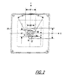
- FIG. 2 shows a top view of the support platform 20 and channel 22 which defines a range of movement of the joystick handle 14.
- the joystick handle 14 is shown in the center of the channel 22 (i.e., at the center of the coordinate system defined by x and y axis 50,52). It should be noted that as the handle 14 is manipulated within the channel 22, its position will appear to be reversed or a "mirror" image of the bottom shaft 18 shown (FIG. la). This is because the handle 14 and bottom shaft 18 represent opposite ends of the joystick 12 which pivots about center ball 16. Thus, for example, when the joystick 12 is in the neutral position, the bottom shaft 18 is at position (0, d) and the handle 14 is at position (0, -d).
- the channel 22 has a generally tear-drop shaped periphery 56 which tapers inwardly toward the ball center 16 of the joystick 12.
- a lower-most (and thereby narrowest) portion of the periphery is designated by reference numeral 561 and an upper-most (widest) portion of the periphery is designated by reference numeral 56u.
- symmetrical angles a on either side of the y axis define the left- and right-most boundaries of the channel 22.
- the angles ⁇ are about 30 degrees.
- the range of angular motion achievable by the joystick is 2 ⁇ , or about 60 degrees.
- the degree of taper of the channel 22 corresponds to the angles ⁇ .
- the degree of taper between the lower-most and upper-most portions of channel 22 is also about 30 degrees.
- the joystick handle 14 when the joystick handle 14 is displaced to the left-most or right-most boundary of the channel 22, it will contact both the upper and lower portions 56u,l of the channel 22 at generally the same time.
- variable "A 1 " represents the distance between the outermost vertical boundaries of the channel 22 at its upper surface (i.e., the distance between the points defining the intersection of upper boundary 56u and the y axis).
- variable “A 2 " represents the distance between the outermost vertical boundaries of the channel 22 at its lower surface (i.e., the distance between the points defining the intersection of lower boundary 561 and the y axis).
- the variable "B 1 " represents the distance between the outermost horizontal boundaries of the channel 22 at its upper surface and the variable “B 2 " represents the distance between the outermost horizontal boundaries of the channel 22 at its lower surface .
- a 1 and B 1 are both about 1.73 inches
- a 2 is about 1.10 inches
- B 2 is about 1.13 inches.
- the distance d defining the displacement of the handle from the origin is about 0.864 inches. It will be appreciated, however, that the channel 22 may define any of several alternative sizes or shapes.
- the channel 22 might comprise, for example, a triangular, square or circular shape.
- channel(s) 22 may be customized for a particular game or may be provided in modular fashion with universal components.
- Modular-type channels may be advantageously employed, for example, in retrofit applications, where one desires to remove the channel associated with a first game and replace it with a channel more appropriate for a second game.
- the joystick assembly 60 includes a joystick 12 having a handle 14, a pivoting center ball 16 and a bottom shaft 18 mounted to a platform 20, each of which generally correspond to the structures of FIGs. 1a and 1b.
- the platform 20 has a cut-out portion defining a channel 62 which restricts the range of motion of the handle 14.
- the channel 62 like the channel 22 in the embodiment of FIGs. 1a and 1b, may comprise virtually any shape including, but not limited to tear-drop, triangular, square or circular shapes.
- the joystick 12 in the illustrated embodiment rests normally in a center-detent position, that is with the handle 14 normally biased to the center of the channel 22 by the pulling force of four springs 24a,b,c,d.
- the joystick assembly 60 (having four springs 24a,b,c,d) may be assembled from the joystick assembly 10 (FIGs. 1a and 1b), on the same platform 20, by simply connecting two additional springs 24c,d to the joystick assembly shown in FIG. 1a.
- the joystick assembly 10 (FIG. 1a) may be assembled from the joystick assembly 60, on the same platform 20, by simply removing the springs 24c,d from the joystick assembly shown in FIG. 3a.
- the springs 24a,b,c,d are connected at one end to respective support rods 26a,b,c,d mounted in the platform 20 and at another end to a support bushing 28 surrounding the bottom shaft 18 of the joystick at a position adjacent the center ball 16.
- the springs 24a,b,c,d are positioned generally parallel to the support platform 20 at a relative depth which is less than one-half the depth (i.e., length) of the bottom shaft.
- the bottom shaft 18 extends radially from the center ball 16 by a distance of about 2 inches, whereas the springs 24a,b,c,d have a maximum depth of less than one inch from the center ball.
- the entire joystick assembly in one embodiment has a depth of about 3 1 ⁇ 2 inches, measured from a bottom of the platform 20 to the distal end of the bottom shaft 18.
- the joystick assembly in one embodiment has a square "footprint" defined by the sides of the support platform 20. In one embodiment, each of the sides is 6.3 inches in length, thus defining a footprint area of 40 square inches. In another embodiment particularly useful in retrofit applications, each of the sides is 4 3/8 inches in length, thus defining a footprint area of about 19 1/8 square inches.
- each of the brackets 30 define generally yoke-shaped structures having a pair of opposing legs 32, 34 connected by a bridging span 36, wherein the bridging span 36 includes an elongated slot 38 for receiving the bottom shaft 18 of the joystick.
- one of the legs 32, 34 includes a generally D-shaped hole 44 sized to receive a distal end of the potentiometer shaft 40 having a complementary shape and the other of each pair of legs 32,34 includes a circular hole 46 sized to receive a distal end of a mounting shaft or axle 48 having a complementary shape.
- Each of the brackets 30 is positioned orthogonally (i.e., at a right angle) to the other bracket 30 and each bracket 30 is thereby responsive to one component of motion of the bottom shaft 18 in a two-dimensional plane (e.g., an "x-y" plane).
- the potentiometers 42a,b are also coupled to the structure 20 along two orthogonal axes such that the respective potentiometer shafts 40a,b rotate to positions corresponding to the positions of the respective brackets 30a,b.
- the potentiometers 42a,b are mounted such that their body remains fixed and only their shafts 40a,b rotate in response to motion of the bottom shaft 18 and brackets 30.
- the potentiometers 42a,b are mounted to the joystick platform with a mounting clip (not shown), which will be described in detail in relation to FIGs. 5b-9d.
- the joystick assembly of FIG. 3a is shown in relation to an x-y coordinate system having an origin at the center of the support platform 20.
- the "y” axis 50 is oriented vertically and the “x" axis 52 oriented horizontally relative to the support platform 20 in FIG. 3a.
- bracket 30a is positioned in alignment with the "y” axis 50 and is movable left and right relative to the "y” axis in response to "x" components of movement of the bottom shaft 18.
- Bracket 30b is positioned in alignment with the "x” axis 52 and is movable up and down relative to the "x" axis in response to "y” components of movement of the bottom shaft 18.
- Movement of the respective brackets 30a,b causes movement of the respective potentiometer shafts 40a,b, thereby communicating electrical signals through leads 54a,b to a controller (not shown) which processes the signals to control movement of the game character, symbol or other item under control.
- the springs 24a,b,c,d are each oriented at an angle of about 45 degrees relative to the respective brackets 30a,b such that upon movement of either bracket 30a,b, each spring 24a,b,c,d contributes a biasing force to the bottom shaft 18.
- the springs 24a,b,c,d in their basic form have a free length of about 1 3 ⁇ 4 inches and, as best observed in FIG. 3a, are pre-loaded to about 1.4 times their initial free length, or about 2 1 ⁇ 2 inches. When fully extended, the springs 24a,b,c,d are stretched to about 1.7 times their initial free length, or about 3 inches.
- the springs 24a,b,c,d may include alternate orientations and/or stretched configurations of the springs 24a,b,c,d.
- the springs 24a,b,c,d will be oriented at an angle relative to the respective brackets 30a,b and will be pre-loaded when the bottom shaft is in its naturally-biased position to produce a non-guided feel (i.e., an absence of preferential motion) when moving the shaft 18 about the x- and y-axes.
- each of the springs 24a,b,c,d are pre-loaded and the bottom shaft 18 is subject to an equal biasing force from each spring 24a,b,c,d thereby producing a net biasing force of zero which maintains the bottom shaft in its center position.
- springs 24a,b will exert a greater biasing force than springs 24c,d thereby producing a net biasing force which tends to pull the joystick back to its center position.
- springs 24c,d will exert a greater biasing force than springs 24a,b thereby producing a net biasing force which also tends to pull the joystick back to its center position.
- springs 24a,b will exert a greater biasing force than springs 24a,b thereby producing a net biasing force which also tends to pull the joystick back to its center position.
- the bottom shaft 18 is moved along the "x" axis 52, it will experience a net biasing force which tends to pull it back toward the center position.
- spring pair 24a,c will contribute a greater biasing force than spring pair 24b,d and conversely, if the bottom shaft is moved to the left, spring pair 24b,d will contribute a greater biasing force than spring pair 24a,c, either of which results in a net biasing force which will tend to pull the bottom shaft 18 toward its center position.
- spring pair 24a,c will contribute a greater biasing force than spring pair 24a,c, either of which results in a net biasing force which will tend to pull the bottom shaft 18 toward its center position.
- Joystick apparatus 60 thereby defines a structure which provides non-preferential movement of the joystick 12 by the action of springs 24a,b,c,d which are mounted parallel to the support structure 20. Because the springs 24a,b,c,d are mounted at a relative depth which is only about one-half the depth reached by the bottom shaft 18, the entire joystick assembly 60 is relatively compact so that it may be mounted within a relatively small space. While this feature is advantageous for any game, it is particularly advantageous in retrofit applications where the available space for the joystick apparatus can be limited by the prior game cabinet design.
- FIG. 4 there is shown a magnified side sectional view of a rotary potentiometer 42 positioned relative to support walls 70,72, which comprise in one embodiment portions of a joystick assembly.
- the potentiometer 42 comprises a rotary potentiometer having a rotatable shaft 40, a body portion 43 and an intermediate shaft section 41.
- the potentiometer 42 may comprise either of the potentiometers 42a,b shown in FIGs. 1a and 1b or 3a and 3b and the support walls 70,72 corresponding portions of the joystick support structure 20 of FIGs, 1a, 1b, 3a, 3b.
- the support walls 70,72 (or a single wall 70) may comprise portions of any structure which uses rotary potentiometers, including structures other than joystick assemblies.
- the body portion 43 is generally disk-shaped, defining an outer flat surface 74, an inner flat surface 76 and a cylindrical surface 78 bridging the inner and outer flat surfaces 74,76.
- the support walls 70,72 have respective openings 80, 82 aligned relative to a horizontal axis 84. Opening 80 is sized to receive the intermediate shaft section 41, and opening 82 is sized to receive the shaft 40 of the potentiometer 42.
- the potentiometer 42 has an overall length of about 1 1 ⁇ 4 inches, the body portion 43 contributing about 1 ⁇ 2 inch, the intermediate shaft section 41 contributing about 1 ⁇ 4 inch and the shaft 40 contributing about 1 ⁇ 2 inch to the overally length, whereas the height of walls 70,72 is about 1 1 ⁇ 4 inch and the distance between walls 70,72 is about 3/8 inch. It will be appreciated, however, that other sizes and configurations of potentiometers and support walls may be used.
- the potentiometer 42 is positioned in alignment with horizontal axis 84 and relative to support walls 70,72 such that the inner flat surface 74 is adjacent to support wall 70, the intermediate shaft section 41 projects through opening 80 and the shaft 40 projects through opening 82.
- the support structure 20 may be provided without a second support wall 72, in which case the potentiometer 42 is positioned in alignment with horizontal axis 84 and relative to support walls 70 such that the inner flat surface 74 is adjacent to support wall 70, the intermediate shaft section 41 projects through opening 80 and the free end of shaft 40 is unsupported by a second support wall.
- the free end of shaft 40 is adapted to engage with a bracket 30 of the type shown in FIGs. 1a and 1b or 3a and 3b or other suitable means so that a desired component of motion of the joystick is communicated to rotational motion of the potentiometer shaft 40.
- securing a potentiometer 42 to a support wall 70 has been accomplished with a mounting nut 100, as shown in FIG. 5a.
- the mounting nut 100 is threadedly engaged with the intermediate shaft section 41 of the potentiometer and tightened such that the potentiometer body 43 is held firmly against the support wall 70.
- This method can adversely affect the failure rate of the potentiometer 42 because it can "pre-load" the potentiometer shaft 40 with a side-loading force which contributes to misalignment of the potentiometer shaft 40 with the desired axis of rotation.
- Such misalignment can hinder or entirely stop (i.e., "seize") rotation of the potentiometer shaft and/or cause it to rotate in an eccentric fashion. This, in turn, can cause premature failure of the potentiometer and/or joystick and can also compromise the accuracy of the control signals obtained from the potentiometer 42. Side-loading, generally, which can result from aggressive use of the joystick, also can contribute to failure and/or inaccuracy of the potentiometer.
- Sidewall 72 can serve to dissipate some of the side-loading forces but, when the potentiometer is fixedly secured with a mounting nut, may also contribute to undesired pre-loading of the potentiometer shaft, especially where the holes 80,82 in the respective sidewalls 70,72 are not perfectly aligned.
- a likely effect of such pre-loading and/or side-loading forces is that the potentiometer shaft 40 becomes misaligned relative to the horizontal axis 84 (e.g., on axis 85, at angle ⁇ relative to axis 84).
- the angle ⁇ will of course vary depending on the amount of such pre-loading and/or side-loading forces, but generally will range from 0 to 3 degrees. Because the mounting nut 100 holds the potentiometer body 43 firmly against the support wall 70, the potentiometer body 43 remains oriented with the horizontal axis 84, out of alignment with the potentiometer shaft 40.
- the structure to which the potentiometer is to be mounted includes only a small space for manipulating the mounting nut, and accordingly the prior art process can be cumbersome and time consuming.
- the prior art process can be cumbersome and time consuming.
- such a confined space is only slightly larger than the mounting nut itself and does not accommodate a quick and/or easy installation of the potentiometer.
- FIG. 5b illustrates the mounting of the potentiometer 42 to the support wall 70 with a mounting clip 86 according to one embodiment of the present invention.
- the mounting clip 86 "non-fixedly” secures the potentiometer body 43 in position against the support wall 70 such that it is permitted a degree of "play” or movement, sometimes referred to as “compliance,” in response to pre-loading or side-loading forces. More particularly, in response to such pre-loading or side-loading forces, the potentiometer shaft 40 moves out of alignment with the horizontal axis 84 (e.g., at angle ⁇ relative to axis 84) in generally the same manner described in relation to FIG. 5a.
- the potentiometer body 43 With the mounting clip, however, the potentiometer body 43 is not held firmly against the support wall 70 but rather is permitted up to about 10 degrees of separation 102 from the support wall 70.
- the effect of this freedom of movement is that the potentiometer body 43 is always aligned with the potentiometer shaft 40, whether it be along axis 84 or 85. Accordingly, rotation of the potentiometer shaft 40 (e.g., in response to movements of the joystick shaft) is not skewed or eccentric in relation to the potentiometer body 43.
- the mounting clip can be mounted much more quickly and easily than a mounting nut because it does not require manipulation of any structure between the small, cramped space between sidewalls 70,72.
- the mounting clip 86 and a process for using the mounting nut 86 will hereinafter be described in greater detail in relation to FIGs. 6a through 9d.
- FIGs. 6a through 6c and 7a and 7b illustrate various steps in using the mounting clip 86 of FIG. 5b to mount a potentiometer to the support wall of FIG. 4. More particularly, FIGs. 6a and 7a show the assembly of FIG. 4 before installation, FIG. 6b during installation and FIG. 6c and 7b after installation of the mounting clip 86. Other view of the mounting clip 86 are shown in FIG. 8 (perspective view relative to joystick assembly, both before and after installation), FIG. 9a (side view), FIG. 9b (front view), FIG. 9c (back view) and FIG. 9d (bottom view).
- the mounting clip 86 comprises a front side segment 88 and back side segment 90 bridged by a top segment 92, thereby defining a generally U-shaped cross section.
- the front side segment 88 turns inwardly at its lower edge to define a bottom flange 94
- the back side segment 90 includes a pair of legs 96,98 (FIG. 7a); and the front side segment 88 has a circular clearance hole 100 and two-semi-circular notches 102a,b (FIG. 8).
- the mounting clip 86 in one embodiment is of unitary construction and is comprised of sheet metal having a thickness of about 20 mils. More particularly, in one embodiment the mounting clip comprises soft-annealed spring steel, S.A.E. specification of 1074 to 1095 (A.S.T.M. specification A 684), hardened to a Rockwell C scale of 40 to 60 units.
- the front and back side segments 88,90 are curved inwardly and are elastically deformable relative to each other between a naturally biased position and an outward flexed position.
- the mounting clip 86 may be constructed from any of several alternative materials or combinations of materials including, but not limited to, extruded nylon or any thermoplastic or thermoset plastic material. Where the mounting clip is constructed of alternative materials, it is generally preferred that it have a thickness greater than 20 mils. For example, in one embodiment, the mounting clip is constructed of plastic and has a thickness of 30 to 40 mils.
- the mounting clip 86 has a height of 0.92 inches, width of 1.09 inches and a depth (between front and back segments 88,90) of 0.58 inches.
- the clearance hole 100 has a diameter of 0.56 inches (before forming), the bottom flange 94 has a depth of about 0.12 inches and the front and back segments 88,90 are curved with a respective radii of curvature of 4.4 and 4.7 degrees.
- the mounting clip 86 may be constructed with alternative dimensions if desired.
- the mounting clip might also be constructed with front and back side segments 88,90 which are curved outwardly, rather than inwardly. In either case, the mounting clip "non-fixedly" secures the potentiometer to the support wall such that the potentiometer is free to move somewhat in response to side-loading forces.
- Mounting of the potentiometer 42 relative to the support wall 70 is accomplished in one embodiment by first placing the mounting clip 86 in the position shown in FIG. 6a, generally above the potentiometer 42, where the inner flat surface 76 of the potentiometer 42 is adjacent to the support wall 70 and the potentiometer shaft 40 penetrates through the opening 80 in the support wall. Where the support structure 20 includes a second support wall 72, the free end of shaft 40 penetrates through the second support wall 72. Then, the mounting clip 86 may be moved downward to the position shown in FIG. 6b, wherein a lower portion of the back side segment 90 is engaged with an upper portion of the support wall 70 and a lower portion of the front side segment 88 is engaged with the outer flat surface 74 of the potentiometer 42.
- the front side segment 88 is flexed outwardly and then the mounting clip 86 is moved downward in a sliding contact with the potentiometer 42 until the bottom flange 94 snaps underneath the body portion 78.
- the front side segment 88 in one embodiment then springs back toward its naturally biased position, with the body portion 78 of the potentiometer being received and retained between the front and back side segments 88,90 and the legs 96,98 straddling the potentiometer shaft 40, as shown in FIG. 5b and 6c.
- the potentiometer body 43 With the potentiometer so mounted, the potentiometer body 43 is not held firmly against the support wall 70 but rather is permitted a degree of separation 102 from the support wall 70, as described in relation to FIG. 5b. Accordingly, the potentiometer body 43 is free to move in response to side-loading forces and remains aligned with the potentiometer shaft 40, thus prolonging the useful life of the potentiometer and maintaining its accuracy.
Abstract
Description
- The present invention relates generally to joystick controllers and, more particularly, to a mounting clip useful for mounting potentiometers in a joystick controller.
- Joysticks are well known devices for controlling movement of devices or symbols. Joysticks are commonly used in video games, for example, to effect real or simulated movement of game characters or symbols on a video display. Generally, joysticks consist of a lever mounted for pivotal movement between various radial positions, wherein electrical output signals corresponding to the joystick positions are communicated to a controller (e.g., game controller). The controller, in turn, processes the electrical signals and, according to a game program, manipulates the character(s) or symbol(s) under control corresponding to the various positions of the joystick.
- Generally, the types and degree of control which may be achieved over the character(s) or symbol(s) in the video game is determined both by the sophistication of the joystick used in the game and by the game program. Virtually all joysticks are capable of providing some directional control, for example, but the degree or precision of such directional control can vary greatly depending on the mechanical and/or electrical characteristics of the joystick. For example, a "4-way" joystick is movable between only four angular positions, 90° apart and an "8-way" joystick is movable between 8 angular positions, 45° apart. Other more sophisticated types of joysticks provide velocity, as well as directional control, by providing electrical output signals to the controller corresponding to the degree of deflection of the joystick from its initial parked or "detent" position. As with directional controls, the degree or precision of velocity controls can also vary greatly depending on the mechanical and/or electrical characteristics of the joystick.
- It is known that high precision directional or velocity control may be achieved by using potentiometers in joystick controllers. One form of potentiometer which may be used for this purpose is an analog rotary potentiometer, which includes a shaft mounted for rotation about an axis such that rotation of the shaft communicates analog electrical signals to the controller. Where two such potentiometers are employed, they are normally coupled to the joystick structure along two orthogonal axes (e.g., an "x" and "y" axis) such that each individual potentiometer shaft rotates to a position corresponding to the displacement component of the joystick along one of the two axes. The combination of the two potentiometers can thereby communicate electrical signals to the controller corresponding to virtually any position of the joystick in a two-dimensional plane (e.g., the "x-y" plane). The electrical output signals, in turn, may be processed by the game controller to provide several hundreds of discrete variables for directional, velocity or other manner of control. Of course, the degree of control depends on the number and configuration of potentiometers employed in the joystick and the characteristics of the game program responsive to the potentiometer signals.
- While analog joysticks generally offer tremendous advantages in control relative to other types of joysticks, both the degree of control which may be achieved by the joysticks and their failure rate can be compromised by the manner in which the potentiometers are mounted to the joystick structure. In particular, a common problem heretofore encountered in analog joysticks is side-loading of the potentiometer shafts. Side-loading may occur as a result of aggressive handling of the joystick controller during use and/or from "pre-loading" or fixedly mounting the potentiometer shaft in misalignment with the desired axis of rotation. In either case, the side-loading forces can result in eccentric rotation of the potentiometer shaft which can cause premature failure of the joystick and decrease its accuracy. This problem is generally exacerbated where the potentiometers are fixedly secured to the joystick structure as presently known (e.g., with a mounting nut) in a manner which does not permit the potentiometer some freedom of motion or "play" to dissipate the side-loading forces.
- Moreover, with the present method of securing potentiometers to the joystick structure with a mounting nut, there is generally only a small, cramped space in the structure wherein the mounting nut is to be secured about the shaft of the potentiometer and, accordingly, the process of manipulating the mounting nut within such small space is generally a cumbersome, rather time consuming process.
- Accordingly, there is a need for a method and apparatus for mounting potentiometers in a joystick controller in a manner that overcomes or at least reduces the effects of the side-loading problems and/or mounting difficulties discussed above. The present invention is directed to addressing this need.
- In accordance with one aspect of the present invention, there is provided a mounting clip for securing a rotary potentiometer relative to a support wall, wherein the potentiometer defines a body portion and a shaft and the support wall has an opening therein for accommodating the potentiometer shaft. The potentiometer and support wall may comprise portions of a joystick assembly. The mounting clip comprises front and back generally vertical opposing side segments and a top segment bridging the front and back side segments. When the potentiometer is secured to the support wall by the mounting clip, the body portion of the potentiometer and a portion of the support wall is received and retained between the front and back side segments of the mounting clip and the potentiometer shaft projects through the opening in the support wall. In a preferred embodiment, the potentiometer shaft when so mounted projects non-fixedly through the opening in the support wall so that both the potentiometer shaft and body are permitted to deflect in response to intermittent side-loading forces.
- In accordance with another aspect of the present invention, there is provided a method of mounting a rotary potentiometer relative to a support wall of a joystick assembly. The potentiometer defines a generally disk-shaped body portion and a shaft, wherein the body portion comprises an outer flat surface and an inner flat surface bridged by a cylindrical surface and the potentiometer shaft projects outwardly from the inner flat surface along a longitudinal axis. The support wall has an opening therein for accommodating the potentiometer shaft. Mounting of the potentiometer is accomplished in one embodiment by first placing the potentiometer in a position wherein the inner flat surface is adjacent to the support wall and the potentiometer shaft penetrates through the opening in the support wall. Next, a mounting clip comprising front and back opposing side segments and a top segment is oriented above the potentiometer in a position wherein the front side segment is oriented generally vertically above the outer flat surface of the potentiometer and a lower portion of the back side segment is engaged with the support wall. The back side segment of the mounting clip defines a pair of legs, a bottom portion of the front side segment turns inwardly toward the back side segment to define a bottom flange, and the front and back side segments are elastically deformable relative to each other between a naturally biased position and an outward flexed position. With the legs of the mounting clip engaged with the back of the support wall, the front side segment is flexed outwardly toward its outward flexed position and the mounting clip is pushed downward in a sliding contact until the bottom flange snaps underneath the body portion of the potentiometer.
- The foregoing and other advantages of the invention will become apparent upon reading the following detailed description and upon reference to the drawings in which:
- FIG. 1a is a bottom view of a joystick assembly having a side-detent characteristic according to one embodiment of the present invention;
- FIG. 1b is a side view of the joystick assembly of FIG. 1a;
- FIG. 2 is a top view of the joystick assembly of FIGs. 1a and 1b illustrating a channel boundary defining a range of movement of the joystick handle according to one embodiment of the present invention;
- FIG. 3a is a bottom view of a joystick assembly having a center-detent characteristic according to one embodiment of the present invention;
- FIG. 3b is a side view of the joystick assembly of FIG. 3a;
- FIG. 4 is a side view of a potentiometer positioned relative to a support wall;
- FIG. 5a is a side view of the potentiometer and support wall of FIG. 4 with the potentiometer mounted in the manner of the prior art;
- FIG. 5b is a side view of the potentiometer and support wall of FIG. 4 with a potentiometer mounting clip according to one embodiment of the present invention;
- FIG. 6a is a side view of the potentiometer and support wall of FIG. 4 with the mounting clip of FIG. 5b before installation;
- FIG. 6b is a side view of the potentiometer and support wall of FIG. 4 with the mounting clip of FIG. 5b during installation;
- FIG. 6c is a side view of the potentiometer and support wall of FIG. 4 with the mounting clip of FIG. 5b after installation;
- FIG. 7a is a perspective view of the potentiometer and support wall of FIG. 4 with the mounting clip of FIG. 5b before installation;
- FIG. 7b is a perspective view of the potentiometer and support wall of FIG. 4 with the mounting clip of FIG. 5b after installation;
- FIG. 8 is a perspective view of the joystick assembly of FIGs, 3a and 3b with mounting clips according to the present invention shown both before and after installation;
- FIG. 9a is a side view of a potentiometer mounting clip of the type shown in FIGs. 5b through 8;
- FIG. 9b is a front view of the potentiometer mounting clip of FIG. 9a;
- FIG. 9c is a back view of the potentiometer mounting clip of FIG. 9a; and
- FIG. 9d is a bottom view of the potentiometer mounting clip of FIG. 9a.
-
- While the invention is susceptible to various modifications and alternative forms, specific embodiments have been shown by way of example in the drawings and will be described in detail herein. However, it should be understood that the invention is not intended to be limited to the particular forms disclosed. Rather, the invention is to cover all modifications, equivalents, and alternatives falling within the spirit and scope of the invention as defined by the appended claims.
- Turning now to the drawings and referring initially to FIGs, 1a and 1b, there is shown a
joystick assembly 10 having a side-detent characteristic according to one embodiment of the present invention. Thejoystick assembly 10 includes ajoystick 12 having ahandle 14, a pivotingcenter ball 16 and abottom shaft 18 mounted to aplatform 20. Theplatform 20 has a cut-out portion defining achannel 22 for receiving thehandle 14. The boundaries of thechannel 22 restricts the range of motion of thehandle 14, as will be described in greater detail in reference to FIG. 2. Thejoystick 12 in the illustrated embodiment rests normally in a side-detent position, that is with thehandle 14 biased toward an outermost edge of thechannel 22 by the pulling force of twospring elements 24a,b. In one embodiment, thespring elements 24a,b each comprise 5-6 in-lb extension springs constructed from music wire or stainless steel. It will be appreciated however, that references to "springs" or "spring elements" throughout this application shall be considered to encompass various alternative types and compositions of springs or spring alternatives. Springs having lesser or greater tension may be used, for example, to effect a different mechanical feel of thejoystick 12. Springs having a different construction might also be used. For example, compression springs may be used, or the spring elements might be constructed from a thermoplastic elastomer (TPE), a substance with generally "rubber-band-like" qualities. - The
springs 24a,b are connected at one end torespective support rods 26a,b mounted in theplatform 20 and at another end to asupport bushing 28 surrounding thebottom shaft 18 of the joystick at a position adjacent thecenter ball 16. Thecenter ball 16 is received within aball race 19 mounted on asubsidiary platform 21. As best observed in FIG. 1b, thesprings 24a,b are positioned generally parallel to thesupport platform 20 at a relative depth which is less than one-half the depth (i.e., length) of the bottom shaft. In one embodiment, for example, thebottom shaft 18 extends radially from thecenter ball 16 by a distance of about 2 inches, whereas thesprings 24a,b have a maximum depth of less than one inch from the center ball. The entire joystick assembly in one embodiment has a depth of about 3 ½ inches, measured from a bottom of theplatform 20 to the distal end of thebottom shaft 18. The joystick assembly in one embodiment has a square "footprint" defined by the sides of thesupport platform 20. In one embodiment, each of the sides of theplatform 20 is 6.3 inches in length, thus defining a footprint area of 40 square inches. In one embodiment, thesubsidiary platform 21 upon which the center ball is mounted also has a square footprint defined by sides which are 4.4 inches in length. - To operate the
joystick 12, one pulls thehandle 14 in a direction generally indicated byarrow 29 against the biasing force of thesprings 24a,b to a desired position within the confines of thechannel 22. Thebottom shaft 18 of the joystick moves cooperatively with thehandle 14 to a position generally opposite that of thehandle 14. Movement of thebottom shaft 18 in turn is communicated by means ofrotatable brackets 30a,b torespective shafts 40a,b of twopotentiometers 42a,b. For convenience, only one of the twobrackets 30a,b is shown in FIGs, 1a and 1b. Each of the brackets 30 define generally yoke-shaped or U-shaped structures having a pair of opposinglegs bridging span 36, wherein thebridging span 36 includes anelongated slot 38 for receiving thebottom shaft 18 of the joystick. In each bracket 30, one of thelegs hole 44 sized to receive a distal end of thepotentiometer shaft 40 having a complementary shape and the other of each pair oflegs circular hole 46 sized to receive a distal end of a mounting shaft oraxle 48 having a complementary shape. - Each of the brackets 30 is positioned orthogonally (i.e., at a right angle) to the other bracket 30 and each bracket 30 is thereby responsive to one component of motion of the
bottom shaft 18 in a two-dimensional plane (e.g., an "x-y" plane). Thepotentiometers 42a,b, in turn, are also coupled to thestructure 20 along two orthogonal axes such that therespective potentiometer shafts 40a,b rotate to positions corresponding to the positions of therespective brackets 30a,b. Thepotentiometers 42a,b are mounted such that their body remains fixed and only theirshafts 40a,b rotate in response to motion of thebottom shaft 18 and brackets 30. In accordance with one aspect of the present invention, thepotentiometers 42a,b are mounted to the joystick platform with a mounting clip (not shown), which will be described in detail in relation to FIGs, 5b through 9d. - For convenience, the joystick assembly of FIG. 1a is shown in relation to an x-y coordinate system having an "x"
axis 52 oriented horizontally and a "y"axis 50 oriented vertically relative to thesupport platform 20. The origin of the x-y coordinate system is at the center of thesupport platform 20. In the embodiment of FIGs, 1a and 1b, therespective brackets bottom shaft 18. In particular,bracket 30a is initially positioned at x = 0 (in alignment with the "y" axis 50) and is movable left and right along the "x" axis in response to "x" components of movement of thebottom shaft 18.Bracket 30b (FIG. 1b) is initially positioned at y = d (parallel to the "x"axis 52 and displaced by a distance d) and is movable along the "y" axis in response to "y" components of movement of thebottom shaft 18. Movement of therespective brackets 30a,b causes movement of therespective potentiometer shafts 40a,b, thereby communicating electrical signals throughleads 54a,b to a controller (not shown) which processes the signals to control movement of the game character, symbol or other item under control. - In the embodiment of FIGs. 1a and 1b, with the
bottom shaft 18 in its naturally-biased position, thesprings 24a,b are oriented at an angle of about 45 degrees relative to therespective brackets 30a,b such upon movement of eitherbracket 30a,b, eachspring 24a,b contributes a biasing force to thebottom shaft 18. In one embodiment, thesprings 24a,b in their basic free-length form have a length of about 1¾ inches and, as best observed in FIG. la, are pre-loaded to about 1.2 times their initial free length, or about 2 ¼ inches. When fully extended, thesprings 24a,b are stretched to about 1.6 times their initial free length, or about 3 inches. It will be appreciated, however, that other designs according to the present invention may include alternate orientations and/or stretched configurations of thesprings 24a,b. Preferably, however, thesprings 24a,b will be oriented at an angle relative to therespective brackets 30a,b and will be pre-loaded when the bottom shaft is in its naturally-biased position to produce a non-guided feel (i.e., an absence of preferential motion) when moving theshaft 18 about the x- and y- axes. - According to well known principles of physics, an unloaded spring (i.e., a spring which is in its initial free-length state), tends to resist displacement from its free-length state and will begin to stretch (in the case of a tension spring) or compress (in the case of a compression spring) only upon application of a force which exceeds a certain discrete load level. The level at which a spring will begin to stretch or compress depends on the physical characteristics of the spring. Once the characteristic load level has been reached, the spring will stretch or compress in linear proportion to the amount of applied force. In the present invention, by pre-loading the springs past their characteristic load level, the initial resistance of the springs to displacement has already been overcome and the springs will stretch in linear proportion to any component of movement of the joystick handle. The effect is that the joystick feels as if it is equally resistant to movement in each direction.
- In particular, consider the forces contributed by the springs in response to various movements of the
bottom shaft 18. In the initial position and at any position along the "y"axis 50, each of thesprings 24a,b are pre-loaded and thebottom shaft 18 is subject to an equal biasing force from eachspring 24a,b. As thebottom shaft 18 is moved incrementally along the "x"axis 52, one of thesprings 24a,b will begin to contribute a greater biasing force than theother spring 24a,b (the degree of force being dependent on the displacement of the bottom shaft in both the x and y axes), but the net biasing force contributed by the twosprings 24a,b does not significantly vary in response to incremental movement of the bottom shaft. Consequently, because the net biasing force contributed by thesprings 24a,b does not appreciably change in response to incremental movements of thejoystick 12, thejoystick 12 exhibits an unguided "feel" as it is moved about the x- and y- axes. Thus, there is no particular axis which may be considered to comprise a "preferential" axis of movement of thejoystick 12. -
Joystick apparatus 10 thereby defines a structure which provides non-preferential movement of thejoystick 12 by the action ofsprings 24a,b which are mounted parallel to thesupport structure 20. Because thesprings 24a,b are mounted at a relative depth which is only about one-half the depth reached by thebottom shaft 18, theentire joystick assembly 10 is relatively compact so that it may be mounted within a relatively small space. For example, the overall mounting depth of the joystick assembly in one embodiment is about 3 ¼ or 3 ½ inches. While this feature is advantageous for any game, it is particularly advantageous in retrofit applications where the available space for the joystick apparatus can be limited by the prior game cabinet design. - FIG. 2 shows a top view of the
support platform 20 andchannel 22 which defines a range of movement of thejoystick handle 14. The joystick handle 14 is shown in the center of the channel 22 (i.e., at the center of the coordinate system defined by x andy axis 50,52). It should be noted that as thehandle 14 is manipulated within thechannel 22, its position will appear to be reversed or a "mirror" image of thebottom shaft 18 shown (FIG. la). This is because thehandle 14 andbottom shaft 18 represent opposite ends of thejoystick 12 which pivots aboutcenter ball 16. Thus, for example, when thejoystick 12 is in the neutral position, thebottom shaft 18 is at position (0, d) and thehandle 14 is at position (0, -d). - In the illustrated embodiment, the
channel 22 has a generally tear-drop shaped periphery 56 which tapers inwardly toward theball center 16 of thejoystick 12. A lower-most (and thereby narrowest) portion of the periphery is designated byreference numeral 561 and an upper-most (widest) portion of the periphery is designated byreference numeral 56u. In one embodiment, symmetrical angles a on either side of the y axis define the left- and right-most boundaries of thechannel 22. In one embodiment, the angles α are about 30 degrees. The range of angular motion achievable by the joystick is 2α, or about 60 degrees. In one embodiment, the degree of taper of thechannel 22 corresponds to the angles α. Thus, where the angle a is about 30 degrees, the degree of taper between the lower-most and upper-most portions ofchannel 22 is also about 30 degrees. Thus, when the joystick handle 14 is displaced to the left-most or right-most boundary of thechannel 22, it will contact both the upper andlower portions 56u,l of thechannel 22 at generally the same time. - In FIG. 2, the variable "A1" represents the distance between the outermost vertical boundaries of the
channel 22 at its upper surface (i.e., the distance between the points defining the intersection ofupper boundary 56u and the y axis). Similarly, the variable "A2" represents the distance between the outermost vertical boundaries of thechannel 22 at its lower surface (i.e., the distance between the points defining the intersection oflower boundary 561 and the y axis). The variable "B1" represents the distance between the outermost horizontal boundaries of thechannel 22 at its upper surface and the variable "B2" represents the distance between the outermost horizontal boundaries of thechannel 22 at its lower surface . In one embodiment, A1 and B1 are both about 1.73 inches, A2 is about 1.10 inches and B2 is about 1.13 inches. In this embodiment, the distance d defining the displacement of the handle from the origin is about 0.864 inches. It will be appreciated, however, that thechannel 22 may define any of several alternative sizes or shapes. Thechannel 22 might comprise, for example, a triangular, square or circular shape. - Such alternative shapes and sizes of channel(s) 22 may be customized for a particular game or may be provided in modular fashion with universal components. Modular-type channels may be advantageously employed, for example, in retrofit applications, where one desires to remove the channel associated with a first game and replace it with a channel more appropriate for a second game.
- Now turning to FIGs, 3a and 3b, there is shown a
joystick assembly 60 having a center-detent characteristic according to one embodiment of the present invention. Thejoystick assembly 60 includes ajoystick 12 having ahandle 14, a pivotingcenter ball 16 and abottom shaft 18 mounted to aplatform 20, each of which generally correspond to the structures of FIGs. 1a and 1b. Theplatform 20 has a cut-out portion defining achannel 62 which restricts the range of motion of thehandle 14. Thechannel 62, like thechannel 22 in the embodiment of FIGs. 1a and 1b, may comprise virtually any shape including, but not limited to tear-drop, triangular, square or circular shapes. Thejoystick 12 in the illustrated embodiment rests normally in a center-detent position, that is with thehandle 14 normally biased to the center of thechannel 22 by the pulling force of foursprings 24a,b,c,d. - According to one embodiment, the joystick assembly 60 (having four
springs 24a,b,c,d) may be assembled from the joystick assembly 10 (FIGs. 1a and 1b), on thesame platform 20, by simply connecting twoadditional springs 24c,d to the joystick assembly shown in FIG. 1a. Conversely, the joystick assembly 10 (FIG. 1a) may be assembled from thejoystick assembly 60, on thesame platform 20, by simply removing thesprings 24c,d from the joystick assembly shown in FIG. 3a. - The
springs 24a,b,c,d are connected at one end torespective support rods 26a,b,c,d mounted in theplatform 20 and at another end to asupport bushing 28 surrounding thebottom shaft 18 of the joystick at a position adjacent thecenter ball 16. As best observed in FIG. 3b, thesprings 24a,b,c,d are positioned generally parallel to thesupport platform 20 at a relative depth which is less than one-half the depth (i.e., length) of the bottom shaft. In one embodiment, for example, thebottom shaft 18 extends radially from thecenter ball 16 by a distance of about 2 inches, whereas thesprings 24a,b,c,d have a maximum depth of less than one inch from the center ball. The entire joystick assembly in one embodiment has a depth of about 3 ½ inches, measured from a bottom of theplatform 20 to the distal end of thebottom shaft 18. The joystick assembly in one embodiment has a square "footprint" defined by the sides of thesupport platform 20. In one embodiment, each of the sides is 6.3 inches in length, thus defining a footprint area of 40 square inches. In another embodiment particularly useful in retrofit applications, each of the sides is 4 3/8 inches in length, thus defining a footprint area of about 19 1/8 square inches. - To operate the
joystick 12, one pulls thehandle 14 in either direction generally indicated byarrows 29 against the biasing force of thesprings 24a,b,c,d to a desired position within the confines of thechannel 62. Thebottom shaft 18 of the joystick moves cooperatively with thehandle 14 to a position generally opposite that of thehandle 14. Movement of thebottom shaft 18 in turn is communicated by means ofrotatable brackets 30a,b torespective shafts 40a,b of twopotentiometers 42a,b. Each of the brackets 30 define generally yoke-shaped structures having a pair of opposinglegs bridging span 36, wherein thebridging span 36 includes anelongated slot 38 for receiving thebottom shaft 18 of the joystick. In each bracket 30, one of thelegs hole 44 sized to receive a distal end of thepotentiometer shaft 40 having a complementary shape and the other of each pair oflegs circular hole 46 sized to receive a distal end of a mounting shaft oraxle 48 having a complementary shape. - Each of the brackets 30 is positioned orthogonally (i.e., at a right angle) to the other bracket 30 and each bracket 30 is thereby responsive to one component of motion of the
bottom shaft 18 in a two-dimensional plane (e.g., an "x-y" plane). Thepotentiometers 42a,b, in turn, are also coupled to thestructure 20 along two orthogonal axes such that therespective potentiometer shafts 40a,b rotate to positions corresponding to the positions of therespective brackets 30a,b. Thepotentiometers 42a,b are mounted such that their body remains fixed and only theirshafts 40a,b rotate in response to motion of thebottom shaft 18 and brackets 30. In accordance with one aspect of the present invention, thepotentiometers 42a,b are mounted to the joystick platform with a mounting clip (not shown), which will be described in detail in relation to FIGs. 5b-9d. - For convenience, the joystick assembly of FIG. 3a is shown in relation to an x-y coordinate system having an origin at the center of the
support platform 20. The "y"axis 50 is oriented vertically and the "x"axis 52 oriented horizontally relative to thesupport platform 20 in FIG. 3a. In the illustrated embodiment,bracket 30a is positioned in alignment with the "y"axis 50 and is movable left and right relative to the "y" axis in response to "x" components of movement of thebottom shaft 18.Bracket 30b is positioned in alignment with the "x"axis 52 and is movable up and down relative to the "x" axis in response to "y" components of movement of thebottom shaft 18. Movement of therespective brackets 30a,b causes movement of therespective potentiometer shafts 40a,b, thereby communicating electrical signals throughleads 54a,b to a controller (not shown) which processes the signals to control movement of the game character, symbol or other item under control. - In the embodiment of FIGs, 3a and 3b, with the
bottom shaft 18 in its naturally-biased center position, thesprings 24a,b,c,d are each oriented at an angle of about 45 degrees relative to therespective brackets 30a,b such that upon movement of eitherbracket 30a,b, eachspring 24a,b,c,d contributes a biasing force to thebottom shaft 18. In one embodiment, thesprings 24a,b,c,d in their basic form have a free length of about 1 ¾ inches and, as best observed in FIG. 3a, are pre-loaded to about 1.4 times their initial free length, or about 2 ½ inches. When fully extended, thesprings 24a,b,c,d are stretched to about 1.7 times their initial free length, or about 3 inches. It will be appreciated, however, that other designs according to the present invention may include alternate orientations and/or stretched configurations of thesprings 24a,b,c,d. Preferably, however, thesprings 24a,b,c,d will be oriented at an angle relative to therespective brackets 30a,b and will be pre-loaded when the bottom shaft is in its naturally-biased position to produce a non-guided feel (i.e., an absence of preferential motion) when moving theshaft 18 about the x- and y-axes. - Thus, for example, consider the forces contributed by the springs in response to various movements of the
bottom shaft 18. In the initial position, each of thesprings 24a,b,c,d are pre-loaded and thebottom shaft 18 is subject to an equal biasing force from eachspring 24a,b,c,d thereby producing a net biasing force of zero which maintains the bottom shaft in its center position. As the bottom shaft is moved downward along the "y"axis 50, springs 24a,b will exert a greater biasing force thansprings 24c,d thereby producing a net biasing force which tends to pull the joystick back to its center position. Conversely, as the bottom shaft is moved upward along the "y"axis 50, springs 24c,d will exert a greater biasing force thansprings 24a,b thereby producing a net biasing force which also tends to pull the joystick back to its center position. Similarly, as thebottom shaft 18 is moved along the "x"axis 52, it will experience a net biasing force which tends to pull it back toward the center position. In particular, if the bottom shaft is moved to the right,spring pair 24a,c will contribute a greater biasing force thanspring pair 24b,d and conversely, if the bottom shaft is moved to the left,spring pair 24b,d will contribute a greater biasing force thanspring pair 24a,c, either of which results in a net biasing force which will tend to pull thebottom shaft 18 toward its center position. Of course, variations of any of the above-described movements in which the bottom shaft has both "x" and "y" components of movement will also produce a net biasing force which tends to pull thebottom shaft 18 back toward its center position. - Although the contributions to the net biasing force from the
individual springs 24a,b,c,d vary according to the position of the joystick, the net biasing force produced by the combination ofsprings 24a,b,c,d does not significantly vary from point to point. Consequently, because of these non-appreciable differences in the net biasing force contributed by thesprings 24a,b as thejoystick 12 is moved, there is no particular axis which may be considered to comprise a "preferential" axis of movement of thejoystick 12. -
Joystick apparatus 60 thereby defines a structure which provides non-preferential movement of thejoystick 12 by the action ofsprings 24a,b,c,d which are mounted parallel to thesupport structure 20. Because thesprings 24a,b,c,d are mounted at a relative depth which is only about one-half the depth reached by thebottom shaft 18, theentire joystick assembly 60 is relatively compact so that it may be mounted within a relatively small space. While this feature is advantageous for any game, it is particularly advantageous in retrofit applications where the available space for the joystick apparatus can be limited by the prior game cabinet design. - Now turning to FIG. 4. there is shown a magnified side sectional view of a
rotary potentiometer 42 positioned relative to supportwalls potentiometer 42 comprises a rotary potentiometer having arotatable shaft 40, abody portion 43 and anintermediate shaft section 41. Thepotentiometer 42 may comprise either of thepotentiometers 42a,b shown in FIGs. 1a and 1b or 3a and 3b and thesupport walls joystick support structure 20 of FIGs, 1a, 1b, 3a, 3b. It will be appreciated, however, that thesupport walls 70,72 (or a single wall 70) may comprise portions of any structure which uses rotary potentiometers, including structures other than joystick assemblies. - The
body portion 43 is generally disk-shaped, defining an outerflat surface 74, an innerflat surface 76 and acylindrical surface 78 bridging the inner and outerflat surfaces support walls respective openings horizontal axis 84.Opening 80 is sized to receive theintermediate shaft section 41, andopening 82 is sized to receive theshaft 40 of thepotentiometer 42. In one embodiment, thepotentiometer 42 has an overall length of about 1 ¼ inches, thebody portion 43 contributing about ½ inch, theintermediate shaft section 41 contributing about ¼ inch and theshaft 40 contributing about ½ inch to the overally length, whereas the height ofwalls walls - The
potentiometer 42 is positioned in alignment withhorizontal axis 84 and relative to supportwalls flat surface 74 is adjacent to supportwall 70, theintermediate shaft section 41 projects throughopening 80 and theshaft 40 projects throughopening 82. Alternatively, thesupport structure 20 may be provided without asecond support wall 72, in which case thepotentiometer 42 is positioned in alignment withhorizontal axis 84 and relative to supportwalls 70 such that the innerflat surface 74 is adjacent to supportwall 70, theintermediate shaft section 41 projects throughopening 80 and the free end ofshaft 40 is unsupported by a second support wall. In either case, the free end ofshaft 40 is adapted to engage with a bracket 30 of the type shown in FIGs. 1a and 1b or 3a and 3b or other suitable means so that a desired component of motion of the joystick is communicated to rotational motion of thepotentiometer shaft 40. - Heretofore, securing a
potentiometer 42 to a support wall 70 (whether the support wall comprises a portion of a joystick assembly or another structure) has been accomplished with a mountingnut 100, as shown in FIG. 5a. The mountingnut 100 is threadedly engaged with theintermediate shaft section 41 of the potentiometer and tightened such that thepotentiometer body 43 is held firmly against thesupport wall 70. This method can adversely affect the failure rate of thepotentiometer 42 because it can "pre-load" thepotentiometer shaft 40 with a side-loading force which contributes to misalignment of thepotentiometer shaft 40 with the desired axis of rotation. Such misalignment can hinder or entirely stop (i.e., "seize") rotation of the potentiometer shaft and/or cause it to rotate in an eccentric fashion. This, in turn, can cause premature failure of the potentiometer and/or joystick and can also compromise the accuracy of the control signals obtained from thepotentiometer 42. Side-loading, generally, which can result from aggressive use of the joystick, also can contribute to failure and/or inaccuracy of the potentiometer.Sidewall 72, where provided, can serve to dissipate some of the side-loading forces but, when the potentiometer is fixedly secured with a mounting nut, may also contribute to undesired pre-loading of the potentiometer shaft, especially where theholes respective sidewalls - As illustrated in FIG. 5a, a likely effect of such pre-loading and/or side-loading forces is that the
potentiometer shaft 40 becomes misaligned relative to the horizontal axis 84 (e.g., onaxis 85, at angle β relative to axis 84). The angle β will of course vary depending on the amount of such pre-loading and/or side-loading forces, but generally will range from 0 to 3 degrees. Because the mountingnut 100 holds thepotentiometer body 43 firmly against thesupport wall 70, thepotentiometer body 43 remains oriented with thehorizontal axis 84, out of alignment with thepotentiometer shaft 40. Accordingly, rotation of the potentiometer shaft 40 (e.g., in response to movements of the joystick shaft) is skewed or eccentric in relation to thepotentiometer body 43. This, as described above, can contribute to inaccurate results, seizing up of the potentiometer shaft and premature failure of thepotentiometer 42. - Moreover, it is often the case that the structure to which the potentiometer is to be mounted includes only a small space for manipulating the mounting nut, and accordingly the prior art process can be cumbersome and time consuming. For example, with reference to FIG. 4, it is observed that there is only a small, cramped space between
sidewalls - FIG. 5b illustrates the mounting of the
potentiometer 42 to thesupport wall 70 with a mountingclip 86 according to one embodiment of the present invention. The mountingclip 86 "non-fixedly" secures thepotentiometer body 43 in position against thesupport wall 70 such that it is permitted a degree of "play" or movement, sometimes referred to as "compliance," in response to pre-loading or side-loading forces. More particularly, in response to such pre-loading or side-loading forces, thepotentiometer shaft 40 moves out of alignment with the horizontal axis 84 (e.g., at angle β relative to axis 84) in generally the same manner described in relation to FIG. 5a. With the mounting clip, however, thepotentiometer body 43 is not held firmly against thesupport wall 70 but rather is permitted up to about 10 degrees ofseparation 102 from thesupport wall 70. The effect of this freedom of movement is that thepotentiometer body 43 is always aligned with thepotentiometer shaft 40, whether it be alongaxis potentiometer body 43. - Moreover, the mounting clip can be mounted much more quickly and easily than a mounting nut because it does not require manipulation of any structure between the small, cramped space between
sidewalls clip 86 and a process for using the mountingnut 86 will hereinafter be described in greater detail in relation to FIGs. 6a through 9d. - FIGs. 6a through 6c and 7a and 7b illustrate various steps in using the mounting
clip 86 of FIG. 5b to mount a potentiometer to the support wall of FIG. 4. More particularly, FIGs. 6a and 7a show the assembly of FIG. 4 before installation, FIG. 6b during installation and FIG. 6c and 7b after installation of the mountingclip 86. Other view of the mountingclip 86 are shown in FIG. 8 (perspective view relative to joystick assembly, both before and after installation), FIG. 9a (side view), FIG. 9b (front view), FIG. 9c (back view) and FIG. 9d (bottom view). - The mounting
clip 86 comprises afront side segment 88 and backside segment 90 bridged by atop segment 92, thereby defining a generally U-shaped cross section. In one embodiment, thefront side segment 88 turns inwardly at its lower edge to define abottom flange 94, theback side segment 90 includes a pair oflegs 96,98 (FIG. 7a); and thefront side segment 88 has acircular clearance hole 100 and two-semi-circular notches 102a,b (FIG. 8). - The mounting
clip 86 in one embodiment is of unitary construction and is comprised of sheet metal having a thickness of about 20 mils. More particularly, in one embodiment the mounting clip comprises soft-annealed spring steel, S.A.E. specification of 1074 to 1095 (A.S.T.M. specification A 684), hardened to a Rockwell C scale of 40 to 60 units. In a preferred embodiment, the front andback side segments - It will be appreciated that the mounting
clip 86 may be constructed from any of several alternative materials or combinations of materials including, but not limited to, extruded nylon or any thermoplastic or thermoset plastic material. Where the mounting clip is constructed of alternative materials, it is generally preferred that it have a thickness greater than 20 mils. For example, in one embodiment, the mounting clip is constructed of plastic and has a thickness of 30 to 40 mils. - In a preferred embodiment, the mounting
clip 86 has a height of 0.92 inches, width of 1.09 inches and a depth (between front andback segments 88,90) of 0.58 inches. Theclearance hole 100 has a diameter of 0.56 inches (before forming), thebottom flange 94 has a depth of about 0.12 inches and the front andback segments clip 86 may be constructed with alternative dimensions if desired. The mounting clip might also be constructed with front andback side segments - Mounting of the
potentiometer 42 relative to thesupport wall 70 is accomplished in one embodiment by first placing the mountingclip 86 in the position shown in FIG. 6a, generally above thepotentiometer 42, where the innerflat surface 76 of thepotentiometer 42 is adjacent to thesupport wall 70 and thepotentiometer shaft 40 penetrates through theopening 80 in the support wall. Where thesupport structure 20 includes asecond support wall 72, the free end ofshaft 40 penetrates through thesecond support wall 72. Then, the mountingclip 86 may be moved downward to the position shown in FIG. 6b, wherein a lower portion of theback side segment 90 is engaged with an upper portion of thesupport wall 70 and a lower portion of thefront side segment 88 is engaged with the outerflat surface 74 of thepotentiometer 42. From the position of FIG. 6b, thefront side segment 88 is flexed outwardly and then the mountingclip 86 is moved downward in a sliding contact with thepotentiometer 42 until thebottom flange 94 snaps underneath thebody portion 78. Thefront side segment 88 in one embodiment then springs back toward its naturally biased position, with thebody portion 78 of the potentiometer being received and retained between the front andback side segments legs potentiometer shaft 40, as shown in FIG. 5b and 6c. - With the potentiometer so mounted, the
potentiometer body 43 is not held firmly against thesupport wall 70 but rather is permitted a degree ofseparation 102 from thesupport wall 70, as described in relation to FIG. 5b. Accordingly, thepotentiometer body 43 is free to move in response to side-loading forces and remains aligned with thepotentiometer shaft 40, thus prolonging the useful life of the potentiometer and maintaining its accuracy. - While the present invention has been described with reference to one or more particular embodiments, those skilled in the art will recognize that many changes may be made thereto without departing from the spirit and scope of the present invention. Each of these embodiments and obvious variations thereof is contemplated as falling within the spirit and scope of the claimed invention, which is set forth in the following claims.
Claims (14)
- A mounting clip for securing a rotary potentiometer relative to a support wall, the potentiometer defining a body portion and a shaft, the support wall having an opening therein for accommodating the potentiometer shaft, the mounting clip comprising front and back generally vertical opposing side segments and a top segment bridging said front and back side segments;
wherein when said potentiometer is secured to said support wall by the mounting clip, the body portion of the potentiometer and a portion of said support wall is received and retained between said front and back side segments of the mounting clip and the potentiometer shaft projects through the opening in the support wall. - The mounting clip of claim 1 wherein when said potentiometer is secured to said support wall by said mounting clip, the potentiometer shaft projects non-fixedly through the opening in the support wall.
- The mounting clip of claim 1 wherein when said potentiometer is secured to said support wall by said mounting clip, the potentiometer shaft is subject to intermittent side-loading forces, the potentiometer shaft projecting non-fixedly through the opening in a manner which permits deflection of the potentiometer shaft in response to said side-loading forces.
- The mounting clip of claim 1 having a generally U-shaped cross section.
- The mounting clip of claim 1 wherein the back side segment comprises a pair of legs, wherein when said potentiometer is secured to said support wall by said mounting clip, the potentiometer shaft projects between said legs and through the opening in the support wall.
- The mounting clip of claim 1 wherein the front and back side segments are elastically deformable relative to each other between a naturally biased position and an outward flexed position, wherein when said potentiometer is secured to said support wall by said mounting clip, the front and back side segments are deformed to the outward flexed position in a position overlying and compressing therebetween the body portion of the potentiometer and a portion of said support wall.
- The mounting clip of claim 1 being of unitary construction.
- The mounting clip of claim 7 comprising spring steel.
- The mounting clip of claim 8 wherein the front and back side segments have a thickness of about 20 mils.
- A mounting clip for securing a rotary potentiometer relative to a support wall of a joystick assembly, the potentiometer defining a generally disk-shaped body portion and a shaft, the body portion comprising an outer flat surface and an inner flat surface bridged by a cylindrical surface, the potentiometer shaft projecting outwardly from the inner flat surface along a longitudinal axis, the support wall having an opening therein for accommodating the potentiometer shaft, the mounting clip comprising front and back generally vertical opposing side segments and a top segment bridging said front and back side segments, the front and back side segments being elastically deformable relative to each other between a naturally biased position and an outward flexed position, wherein when said potentiometer is secured to said support wall by the mounting clip, the front and back side segments are deformed outwardly in a position overlying and compressing therebetween the body portion of the potentiometer and a portion of said support wall such that the outer flat surface of the potentiometer is adjacent to the front side segment of the mounting clip, the inner flat surface of the potentiometer is adjacent to the support wall and the potentiometer shaft projects through the opening in the support wall.
- The mounting clip of claim 10 wherein a bottom portion of the front side segment turns inwardly toward the back side segment to define a bottom flange, the bottom flange underlying a portion of the cylindrical surface of the potentiometer and retaining the mounting clip in position about the potentiometer when said potentiometer is secured to said support wall by the mounting clip.
- The mounting clip of claim 10 wherein the front side segment of the mounting clip has a generally circular opening therein defining a clearance hole, wherein when said potentiometer is secured to said support wall by said mounting clip, the clearance hole is centered about the longitudinal axis such that it overlies a center portion of the outer flat surface of the potentiometer.
- The mounting clip of claim 10 wherein the potentiometer includes a group of electrical terminals for receiving wires extending sidewardly from the cylindrical surface, the front side segment of the mounting clip defining at least one wire clearance notch, wherein when said potentiometer is secured to said support wall by said mounting clip, the wire clearance notch generally overlies the electrical terminals thereby providing clearance space for the electrical wires.
- A method of mounting a rotary potentiometer relative to a support wall of a joystick assembly, the potentiometer defining a generally disk-shaped body portion and a shaft, the body portion comprising an outer flat surface and an inner flat surface bridged by a cylindrical surface, the potentiometer shaft projecting outwardly from the inner flat surface along a longitudinal axis, the support wall having an opening therein for accommodating the potentiometer shaft, the method comprising the steps of:placing the potentiometer in a position wherein the inner flat surface is adjacent to the support wall and the potentiometer shaft penetrates through the opening in the support wall;obtaining a mounting clip comprising front and back opposing side segments and a top segment bridging said front and back side segments, the back side segment defining a pair of legs, a bottom portion of the front side segment turning inwardly toward the back side segment to define a bottom flange, and the front and back side segments being elastically deformable relative to each other between a naturally biased position and an outward flexed position,orienting the mounting clip above the potentiometer in a position wherein a lower portion of the front side segment is engaged with the outer flat surface of the potentiometer and a lower portion of the back side segment is engaged with the support wall;flexing the front side segment outwardly toward its outward flexed position;sliding the mounting clip downward to a position wherein the bottom flange snaps underneath the body portion of the potentiometer, the front side segment thereby springing back toward its naturally biased position, the body portion of the potentiometer thereby being received and retained between said front and back side segments and the legs straddling the potentiometer shaft.
Applications Claiming Priority (2)
| Application Number | Priority Date | Filing Date | Title |
|---|---|---|---|
| US09/187,629 US6040758A (en) | 1998-11-06 | 1998-11-06 | Potentiometer mounting clip for a joystick controller |
| US187629 | 1998-11-16 |
Publications (2)
| Publication Number | Publication Date |
|---|---|
| EP1001328A2 true EP1001328A2 (en) | 2000-05-17 |
| EP1001328A3 EP1001328A3 (en) | 2001-06-06 |
Family
ID=22689782
Family Applications (1)
| Application Number | Title | Priority Date | Filing Date |
|---|---|---|---|
| EP99402798A Withdrawn EP1001328A3 (en) | 1998-11-06 | 1999-11-10 | Potentiometer mounting clip for a joystick |
Country Status (2)
| Country | Link |
|---|---|
| US (2) | US6040758A (en) |
| EP (1) | EP1001328A3 (en) |
Families Citing this family (27)
| Publication number | Priority date | Publication date | Assignee | Title |
|---|---|---|---|---|
| US5889508A (en) | 1996-09-26 | 1999-03-30 | Slotta; Mark R. | Cushion for keyboard cursor control stick |
| US6621485B1 (en) * | 1996-09-26 | 2003-09-16 | Giv, Llc | Gel cushion for keyboard cursor control stick |
| US6724369B2 (en) * | 1996-09-26 | 2004-04-20 | Giv, Llc | Textured cushion for keyboard cursor control stick |
| US20070063974A1 (en) * | 1996-09-26 | 2007-03-22 | Slotta Mark R | Textured cushion for cursor control stick |
| US20100124634A1 (en) * | 1996-09-26 | 2010-05-20 | Slotta Mark R | Cushioned cap with annular portion and method for forming same |
| US8120579B2 (en) * | 1996-09-26 | 2012-02-21 | Giv, Llc | Textured cushion for cursor control stick |
| JP3371873B2 (en) * | 1999-12-22 | 2003-01-27 | 日本電気株式会社 | Liquid crystal display device and adjustment method thereof |
| US7138977B2 (en) * | 2003-01-15 | 2006-11-21 | Motorola, Inc. | Proportional force input apparatus for an electronic device |
| US20050275624A1 (en) * | 2004-06-14 | 2005-12-15 | Siemens Information And Communication Mobile Llc | Hand-held communication device having folding joystick |
| ATE441888T1 (en) * | 2004-07-09 | 2009-09-15 | Gylling Invest Ab | COMPUTER INPUT DEVICE |
| JP4566088B2 (en) * | 2005-08-05 | 2010-10-20 | 任天堂株式会社 | Origin return mechanism for operation member and multidirectional input device using the same |
| US7304232B1 (en) * | 2006-02-11 | 2007-12-04 | Postell Mood Nicholes | Joystick gain control for dual independent audio signals |
| US9161817B2 (en) | 2008-03-27 | 2015-10-20 | St. Jude Medical, Atrial Fibrillation Division, Inc. | Robotic catheter system |
| US20090248042A1 (en) * | 2008-03-27 | 2009-10-01 | Kirschenman Mark B | Model catheter input device |
| WO2009120992A2 (en) * | 2008-03-27 | 2009-10-01 | St. Jude Medical, Arrial Fibrillation Division Inc. | Robotic castheter system input device |
| US8317745B2 (en) * | 2008-03-27 | 2012-11-27 | St. Jude Medical, Atrial Fibrillation Division, Inc. | Robotic catheter rotatable device cartridge |
| US8684962B2 (en) * | 2008-03-27 | 2014-04-01 | St. Jude Medical, Atrial Fibrillation Division, Inc. | Robotic catheter device cartridge |
| US8317744B2 (en) | 2008-03-27 | 2012-11-27 | St. Jude Medical, Atrial Fibrillation Division, Inc. | Robotic catheter manipulator assembly |
| US8343096B2 (en) | 2008-03-27 | 2013-01-01 | St. Jude Medical, Atrial Fibrillation Division, Inc. | Robotic catheter system |
| US9241768B2 (en) * | 2008-03-27 | 2016-01-26 | St. Jude Medical, Atrial Fibrillation Division, Inc. | Intelligent input device controller for a robotic catheter system |
| US8641664B2 (en) | 2008-03-27 | 2014-02-04 | St. Jude Medical, Atrial Fibrillation Division, Inc. | Robotic catheter system with dynamic response |
| JP5773884B2 (en) * | 2008-12-31 | 2015-09-02 | セント・ジュード・メディカル・エイトリアル・フィブリレーション・ディヴィジョン・インコーポレーテッド | Robot catheter system input device |
| US9330497B2 (en) | 2011-08-12 | 2016-05-03 | St. Jude Medical, Atrial Fibrillation Division, Inc. | User interface devices for electrophysiology lab diagnostic and therapeutic equipment |
| US9439736B2 (en) | 2009-07-22 | 2016-09-13 | St. Jude Medical, Atrial Fibrillation Division, Inc. | System and method for controlling a remote medical device guidance system in three-dimensions using gestures |
| WO2011123669A1 (en) | 2010-03-31 | 2011-10-06 | St. Jude Medical, Atrial Fibrillation Division, Inc. | Intuitive user interface control for remote catheter navigation and 3d mapping and visualization systems |
| US8587522B2 (en) | 2011-01-18 | 2013-11-19 | Aaron DeJule | Mouse for operating an electronic device |
| US9056668B2 (en) * | 2012-07-12 | 2015-06-16 | Honeywell International Inc. | Aircraft control stick operational in active and passive modes |
Citations (5)
| Publication number | Priority date | Publication date | Assignee | Title |
|---|---|---|---|---|
| US3939451A (en) * | 1972-09-06 | 1976-02-17 | Alps Electric Co., Ltd. | Balance control for use in 4-channel stereophonic system |
| US4436971A (en) * | 1982-04-23 | 1984-03-13 | Wico Corporation | Snap-in switch mounting structure |
| US4489304A (en) * | 1983-07-22 | 1984-12-18 | Hayes Charles L | Spring disconnect mechanism for self centering multiple axis analog control stick |
| US4883397A (en) * | 1988-02-24 | 1989-11-28 | Rapid S.A. | U-shaped fastening clip device with resilient tongue member |
| EP0349714A2 (en) * | 1988-07-08 | 1990-01-10 | Hayes Technology | Joystick with spring disconnect |
Family Cites Families (23)
| Publication number | Priority date | Publication date | Assignee | Title |
|---|---|---|---|---|
| US2566886A (en) * | 1946-12-04 | 1951-09-04 | Tinnerman Products Inc | Resilient fastening device for objects in adjustable axial relationship |
| US2744986A (en) * | 1953-02-06 | 1956-05-08 | Bill Jack Scient Instr Company | Potentiometer and method of making |
| NL97623C (en) * | 1955-05-03 | |||
| US2942220A (en) * | 1956-11-13 | 1960-06-21 | Gen Motors Corp | Control device |
| US3047682A (en) * | 1958-07-18 | 1962-07-31 | Cutler Hammer Inc | Electric switches |
| US3434342A (en) * | 1965-12-06 | 1969-03-25 | Lear Siegler Inc | Force sensing apparatus |
| US3765065A (en) * | 1972-05-04 | 1973-10-16 | Gen Motors Corp | Bearing locking device |
| US4306208A (en) * | 1978-05-30 | 1981-12-15 | Ledex, Inc. | Joy-stick controller |
| US4250378A (en) * | 1978-10-06 | 1981-02-10 | Tektronix, Inc. | Photoelectric joystick |
| US4305007A (en) * | 1979-08-22 | 1981-12-08 | Gerald N. Stan | Electronic two directional control apparatus |
| GB2091423B (en) * | 1981-01-21 | 1984-05-02 | Bideford Electronics Ltd | Control lever device |
| US4685678A (en) * | 1982-08-13 | 1987-08-11 | Bally Manufacturing Corporation | Position transducer system for a joystick |
| US4856785A (en) * | 1983-03-01 | 1989-08-15 | Williams Electronics, Inc. | Optical dual function joystick |
| US4601247A (en) * | 1984-08-15 | 1986-07-22 | Modular Systems, Inc. | Resilient fastener clip and joint therefor |
| US4738007A (en) * | 1987-07-01 | 1988-04-19 | Demarest Russell G Jun | Clip for stacked sheets |
| US4771807A (en) * | 1987-07-01 | 1988-09-20 | Cooper Industries, Inc. | Stepping actuator |
| US5201799A (en) * | 1991-05-20 | 1993-04-13 | United Technologies Corporation | Clip attachment for combustor panel |
| GB9116523D0 (en) * | 1991-07-31 | 1991-09-11 | Raychem Sa Nv | Electrical component |
| US5317301A (en) * | 1992-07-15 | 1994-05-31 | Devolpi Dean | Joy stick |
| US5374204A (en) * | 1993-11-30 | 1994-12-20 | The Whitake Corporation | Electrical terminal with compliant pin section |
| JPH0831606A (en) * | 1994-07-19 | 1996-02-02 | Murata Mfg Co Ltd | Electronic part |
| US5915758A (en) * | 1995-11-24 | 1999-06-29 | Alfiero; Joseph A. | Bridge for low resistance electrical connections and method of using same |
| KR0181092B1 (en) * | 1996-04-30 | 1999-05-15 | 배순훈 | Heat sink for use in an electronic circuit part |
-
1998
- 1998-11-06 US US09/187,629 patent/US6040758A/en not_active Expired - Fee Related
-
1999
- 1999-11-10 EP EP99402798A patent/EP1001328A3/en not_active Withdrawn
- 1999-11-15 US US09/439,699 patent/US6405432B1/en not_active Expired - Fee Related
Patent Citations (5)
| Publication number | Priority date | Publication date | Assignee | Title |
|---|---|---|---|---|
| US3939451A (en) * | 1972-09-06 | 1976-02-17 | Alps Electric Co., Ltd. | Balance control for use in 4-channel stereophonic system |
| US4436971A (en) * | 1982-04-23 | 1984-03-13 | Wico Corporation | Snap-in switch mounting structure |
| US4489304A (en) * | 1983-07-22 | 1984-12-18 | Hayes Charles L | Spring disconnect mechanism for self centering multiple axis analog control stick |
| US4883397A (en) * | 1988-02-24 | 1989-11-28 | Rapid S.A. | U-shaped fastening clip device with resilient tongue member |
| EP0349714A2 (en) * | 1988-07-08 | 1990-01-10 | Hayes Technology | Joystick with spring disconnect |
Also Published As
| Publication number | Publication date |
|---|---|
| EP1001328A3 (en) | 2001-06-06 |
| US6405432B1 (en) | 2002-06-18 |
| US6040758A (en) | 2000-03-21 |
Similar Documents
| Publication | Publication Date | Title |
|---|---|---|
| US6040758A (en) | Potentiometer mounting clip for a joystick controller | |
| CN107847798B (en) | Rocker with adjustable tension | |
| US6589118B1 (en) | Analog input device to input multi directional signals | |
| US4620176A (en) | Control stick mechanism | |
| US6080941A (en) | Multi-directional key switch assembly | |
| JPH0751625Y2 (en) | Joystick | |
| US20070007112A1 (en) | Multidirectional input device | |
| US8717284B2 (en) | User interface device | |
| US4641123A (en) | Joystick control | |
| US20160020045A1 (en) | System for dynamically adjustable detent | |
| KR20010020640A (en) | Dual axis articulated computer input device and method of operation | |
| EP2113819A2 (en) | Multi-directional input apparatus | |
| KR100676990B1 (en) | Ratchet device for an electrical component which may be adjusted by rotation | |
| US6689977B2 (en) | Keyswitch having a keytop that is upwardly and downwardly movable and method of assembling the same | |
| EP1302835B1 (en) | Force-feedback input device containing two tilt position detection means for operating member | |
| EP0999487A2 (en) | Analogue joystick | |
| JP3813806B2 (en) | Multi-directional input device | |
| US6275139B1 (en) | Multidirectional input device | |
| JP4772755B2 (en) | Multi-directional input device | |
| US20020174736A1 (en) | Precision control joystick unit | |
| CN1949427A (en) | Rotary electronic component and method of manufacturing the same | |
| JP4810667B2 (en) | Joystick controller | |
| JP4022364B2 (en) | Multi-directional input device | |
| JP3723714B2 (en) | Rotating electrical parts | |
| JPH08221129A (en) | Joy stick type controller |
Legal Events
| Date | Code | Title | Description |
|---|---|---|---|
| PUAI | Public reference made under article 153(3) epc to a published international application that has entered the european phase |
Free format text: ORIGINAL CODE: 0009012 |
|
| AK | Designated contracting states |
Kind code of ref document: A2 Designated state(s): DE FR GB IT |
|
| AX | Request for extension of the european patent |
Free format text: AL;LT;LV;MK;RO;SI |
|
| PUAL | Search report despatched |
Free format text: ORIGINAL CODE: 0009013 |
|
| AK | Designated contracting states |
Kind code of ref document: A3 Designated state(s): AT BE CH CY DE DK ES FI FR GB GR IE IT LI LU MC NL PT SE |
|
| AX | Request for extension of the european patent |
Free format text: AL;LT;LV;MK;RO;SI |
|
| 17P | Request for examination filed |
Effective date: 20010625 |
|
| AKX | Designation fees paid |
Free format text: DE FR GB IT |
|
| STAA | Information on the status of an ep patent application or granted ep patent |
Free format text: STATUS: THE APPLICATION IS DEEMED TO BE WITHDRAWN |
|
| 18D | Application deemed to be withdrawn |
Effective date: 20030603 |