EP1528449A1 - Device for controlling an apparatus - Google Patents
Device for controlling an apparatus Download PDFInfo
- Publication number
- EP1528449A1 EP1528449A1 EP05002529A EP05002529A EP1528449A1 EP 1528449 A1 EP1528449 A1 EP 1528449A1 EP 05002529 A EP05002529 A EP 05002529A EP 05002529 A EP05002529 A EP 05002529A EP 1528449 A1 EP1528449 A1 EP 1528449A1
- Authority
- EP
- European Patent Office
- Prior art keywords
- axis
- guide element
- elements
- guide
- holding arm
- Prior art date
- Legal status (The legal status is an assumption and is not a legal conclusion. Google has not performed a legal analysis and makes no representation as to the accuracy of the status listed.)
- Granted
Links
Images


Classifications
-
- G—PHYSICS
- G05—CONTROLLING; REGULATING
- G05G—CONTROL DEVICES OR SYSTEMS INSOFAR AS CHARACTERISED BY MECHANICAL FEATURES ONLY
- G05G9/00—Manually-actuated control mechanisms provided with one single controlling member co-operating with two or more controlled members, e.g. selectively, simultaneously
- G05G9/02—Manually-actuated control mechanisms provided with one single controlling member co-operating with two or more controlled members, e.g. selectively, simultaneously the controlling member being movable in different independent ways, movement in each individual way actuating one controlled member only
- G05G9/04—Manually-actuated control mechanisms provided with one single controlling member co-operating with two or more controlled members, e.g. selectively, simultaneously the controlling member being movable in different independent ways, movement in each individual way actuating one controlled member only in which movement in two or more ways can occur simultaneously
- G05G9/047—Manually-actuated control mechanisms provided with one single controlling member co-operating with two or more controlled members, e.g. selectively, simultaneously the controlling member being movable in different independent ways, movement in each individual way actuating one controlled member only in which movement in two or more ways can occur simultaneously the controlling member being movable by hand about orthogonal axes, e.g. joysticks
- G05G2009/04703—Mounting of controlling member
- G05G2009/04714—Mounting of controlling member with orthogonal axes
- G05G2009/04718—Mounting of controlling member with orthogonal axes with cardan or gimbal type joint
-
- Y—GENERAL TAGGING OF NEW TECHNOLOGICAL DEVELOPMENTS; GENERAL TAGGING OF CROSS-SECTIONAL TECHNOLOGIES SPANNING OVER SEVERAL SECTIONS OF THE IPC; TECHNICAL SUBJECTS COVERED BY FORMER USPC CROSS-REFERENCE ART COLLECTIONS [XRACs] AND DIGESTS
- Y10—TECHNICAL SUBJECTS COVERED BY FORMER USPC
- Y10T—TECHNICAL SUBJECTS COVERED BY FORMER US CLASSIFICATION
- Y10T74/00—Machine element or mechanism
- Y10T74/20—Control lever and linkage systems
- Y10T74/20012—Multiple controlled elements
- Y10T74/20018—Transmission control
- Y10T74/2003—Electrical actuator
-
- Y—GENERAL TAGGING OF NEW TECHNOLOGICAL DEVELOPMENTS; GENERAL TAGGING OF CROSS-SECTIONAL TECHNOLOGIES SPANNING OVER SEVERAL SECTIONS OF THE IPC; TECHNICAL SUBJECTS COVERED BY FORMER USPC CROSS-REFERENCE ART COLLECTIONS [XRACs] AND DIGESTS
- Y10—TECHNICAL SUBJECTS COVERED BY FORMER USPC
- Y10T—TECHNICAL SUBJECTS COVERED BY FORMER US CLASSIFICATION
- Y10T74/00—Machine element or mechanism
- Y10T74/20—Control lever and linkage systems
- Y10T74/20012—Multiple controlled elements
- Y10T74/20201—Control moves in two planes
Definitions
- the present invention relates to a device for Controlling a device, such as aircraft, Airplane simulator, robot od. Like., With a handle, which about two mutually perpendicular axes is movable.
- Such devices are in a variety of forms and Version known and used in the market. she serve primarily to control an aircraft, Flight simulator, robot od. Like. Element.
- a handle is essentially about two axes pivotable about a control of a corresponding To set up.
- a disadvantage of conventional devices is that these are extremely large and complex, if this For example, with drive motors for the corresponding two Movement axes are equipped to a movement of the Follow track and / or control. In addition are These facilities are far too complex and expensive, so that they find only limited use and application.
- WO 81/02208 a device for controlling Liquid transport devices described. These Device has a joystick, which by two staggered axes is movable.
- US 4,520,355 describes a joystick, which with a plurality of potentiometers in the respective axes is provided to have a corresponding twist angle to generate a signal.
- EP 0 151 479 describes a Joystick, which strain gauges are assigned. If the joystick is moved, then the Motion measuring signals displayed on a screen are representable.
- US 4,772,836 discloses a motorized electric described control device for stabilized weapons in a tank, in particular for moving pipes of Machine guns of tanks. It becomes a movement a joystick via externally connected motors braked.
- the present invention is based on the object To provide device of the type mentioned, which eliminates the disadvantages mentioned and with which simple and inexpensive way a device for exact taxation of facilities of all kinds is possible.
- the two guide elements can be inside Drive elements, drive motors include, which the Support movement of the handle and, if necessary computer-controlled and forced, so that a appropriate movement is not carried out too fast.
- Such a device offers many things Applications, especially in the air and Aerospace. However, the invention should not be limited to these Application be limited.
- an inventive Device to any devices, flight simulators, Robot od. Like. Use.
- a robot for example, as a surgical aid possible.
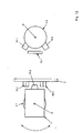
- an apparatus R 1 has a housing 1 in which a first guide element 3.1 is arranged so as to be rotatable about an axis A on an end wall 2.
- the guide element 3.1 is connected to a drive device 4.1, in particular a preferably electrically operated Drive motor 5.1 and a subsequent transmission 6.1 in Compound, as shown in more detail in Figures 3 and 4 is.
- a drive device 4.1 in particular a preferably electrically operated Drive motor 5.1 and a subsequent transmission 6.1 in Compound, as shown in more detail in Figures 3 and 4 is.
- the guide element 3.1 has in the preferred Embodiment, a holding arm 7, which from the A axis approximately at right angles by means of a holding plate. 8 runs out and with it approximately at right angles then receiving plate 9 a right angle forms.
- the receiving plate 9 extends approximately parallel to Axis A.
- On the receiving plate 9 is preferably at right angles to A axis A a second guide element 3.2 stored, which via a second drive device 4.2, in particular Drive motor 5.2 is rotatably mounted about the axis B.
- the handle 10 and / or the guide element 3.2 can at least one force sensor 11.1, 11.2 be assigned, as it is shown in particular in Figures 1 to 3.
- the force sensor 11.1, 11.2 has the task at a manually moving the handle 10 a force and a Detecting movement direction to a forced leadership or also a supported movement of the handle 10 in FIG the respective desired direction by appropriate Twisting the guide elements 3.1, 3.2 by means of Drive devices 4.1, 4.2 allow.
- the embodiment of the present shows Invention according to Figure 5, that the guide element 3.1 via Bearing elements 13 mounted relative to the housing 1 on one side is.
- bearing elements 13 can be used so that the guide element 3.1 on one side about the axis A rotatable relative to the housing. 1 can be stored.
- the bearing elements 13 can be large Absorb forces.
- the guide element 3.1 closes as its component the holding arm 7 at an angle. It sits the guide element 3.1 the holding plate 8, to which eccentric to the axis A and approximately parallel to the axis A, the receiving plate. 9 adjoined. There bearing elements 14 are arranged, which is the Guide element 3.2 rotatable and pivotable about the axis B store.
- a device R 2 is shown in which essentially all the components described above are included according to FIGS. 1 to 5. It is different that the guide element 3.2 with integrated drive device 4.2 at both ends is rotatably mounted relative to the support arm 7 via additional bearing elements 14 about the axis B. A two-sided storage is realized here. For this purpose, another receiving plate 9 adjoins the holding plate 8 at the other end.
- a device R 3 is shown, in which according to the embodiment according to Figure 6, although the guide elements 3.2 are mounted on both sides about the axis B, but the support arm 7 not only at one end on the bearing elements 13 but also at the other end via further bearing elements 13, as schematically indicated here about the axis A is rotatably mounted. At a two-sided storage is thought here.
- a device R 4 is shown, in which the guide element 3.2 according to the embodiment of the device R 1 according to Figure 5 is mounted on one side about the axis B rotatable.
- the retaining arm 7 rotatable on both sides about the axis A, as schematically indicated, stored on the other bearing elements 13. Also, this type of storage is intended by the present Be inventive thought includes.
- a device R 5 is shown, which substantially corresponds to its structure of the device according to Figures 1 to 4.
- Stopperlemente 16.1, 16.2 can control the movement of the Limit guide element 3.1, 3.2. Close this frontally to the guide element 3.2.
- stop element 15.1 and stopper element 16.1, 16.2 approximately close to the axis A. arranged within the holding plate 8 of the holding arm 7.
- another stop element 15.2 is preferably fixed to the end wall 2 of the housing 1, with the both radially to the support plate 8 of the retaining arm.
- 7 Rear side arranged stopper elements 16.3, 16.4 a Direction of movement of the guide element 3.1 about the axis A. to restrict.
- the operation of the device R 5 is shown schematically as a plan view.
- the movement of the guide element 3.1, about the axis A by the stop element 15.2 which end side of the holding plate 8 and / or the receiving plate 9 is arranged opposite two arranged on the end wall 2 of the housing 1 stopper elements 16.3, 16.4, as well as in Figure 12th shown limited.
- the stopper elements 16.1 to 16.4 have corresponding adjusting devices to a limit exact stop accordingly.
- the stopper elements 16.1 to 16.4 as well as the Stop elements 15.1, 15.2 can be made of nylon, metal od. Like. Materials also be made in combination. It is also thought of the corresponding SLOPPER elements 16.1 to 16.4 to dampen a hitting one Dampen stop.
Abstract
Description
Die vorliegende Erfindung betrifft eine Vorrichtung zum Steuern einer Einrichtung, wie bspw. Flugzeug, Flugzeugsimulator, Roboter od. dgl., mit einem Handgriff, welcher um zwei senkrecht zueinander stehenden Achsen bewegbar ist.The present invention relates to a device for Controlling a device, such as aircraft, Airplane simulator, robot od. Like., With a handle, which about two mutually perpendicular axes is movable.
Derartige Vorrichtungen sind in vielfältigster Form und Ausführung auf dem Markt bekannt und gebräuchlich. Sie dienen in erster Linie zur Steuerung eines Flugzeuges, Flugsimulators, Roboters od. dgl. Element.Such devices are in a variety of forms and Version known and used in the market. she serve primarily to control an aircraft, Flight simulator, robot od. Like. Element.
Dabei ist ein Handgriff im wesentlichem um zwei Achsen verschwenkbar um eine Steuerung einer entsprechenden Einrichtung vorzunehmen.A handle is essentially about two axes pivotable about a control of a corresponding To set up.
Nachteilig bei herkömmlichen Vorrichtungen ist, dass diese äusserst gross und komplex ausgebildet sind, wenn diese bspw. mit Antriebsmotoren für die entsprechenden beiden Bewegungsachsen bestückt sind, um eine Bewegung des Handgriffes nachzuführen und/oder zu steuern. Zudem sind diese Einrichtungen viel zu komplex und teuer aufgebaut, so dass diese nur begrenzten Einsatz und Anwendung finden.A disadvantage of conventional devices is that these are extremely large and complex, if this For example, with drive motors for the corresponding two Movement axes are equipped to a movement of the Follow track and / or control. In addition are These facilities are far too complex and expensive, so that they find only limited use and application.
Nach der WO 81/02208 ist eine Vorrichtung zum Steuern von Flüssigkeitstransporteinrichtungen beschrieben. Diese Vorrichtung weist einen Steuerknüppel auf, welcher um zwei versetzt zueinander liegende Achsen bewegbar ist.According to WO 81/02208 a device for controlling Liquid transport devices described. These Device has a joystick, which by two staggered axes is movable.
Die US 4,520,355 beschreibt einen Joystick, welcher mit einer Mehrzahl von Potentiometer in den jeweiligen Achsen versehen ist, um über einen entsprechenden Verdrehwinkel ein Signal zu erzeugen. Die EP 0 151 479 beschreibt einen Joystick, welchem Dehnungsmessstreifen zugeordnet sind. Wird der Joystick bewegt, so erzeugen die Bewegungsmessstreifen Signale, welche auf einem Bildschirm darstellbar sind.US 4,520,355 describes a joystick, which with a plurality of potentiometers in the respective axes is provided to have a corresponding twist angle to generate a signal. EP 0 151 479 describes a Joystick, which strain gauges are assigned. If the joystick is moved, then the Motion measuring signals displayed on a screen are representable.
Die US 4,772,836 offenbart eine motorisierte elektrisch beschriebene Steuerungseinrichtung für stabilisierte Waffen in einem Panzer, insbesondere zur Bewegung von Rohren von Maschinenkanonen von Panzern. Dabei wird eine Bewegung eines Steuerknüppels über extern anschliessende Motoren gebremst.US 4,772,836 discloses a motorized electric described control device for stabilized weapons in a tank, in particular for moving pipes of Machine guns of tanks. It becomes a movement a joystick via externally connected motors braked.
Der vorliegenden Erfindung liegt die Aufgabe zugrunde eine Vorrichtung der eingangs genannten Art zu schaffen, welche die genannten Nachteile beseitigt und mit welcher auf einfache und kostengünstige Weise eine vorrichtung zum exakten Steuern von Einrichtungen aller Art möglich ist. The present invention is based on the object To provide device of the type mentioned, which eliminates the disadvantages mentioned and with which simple and inexpensive way a device for exact taxation of facilities of all kinds is possible.
Zur Lösung dieser Aufgabe führen die Merkmale des
Patentanspruches 1.To solve this problem, the features of the
Bei der vorliegenden Erfindung ist von Bedeutung, dass ein Handgriff zur Steuerung der Einrichtung um zwei Achsen, die senkrecht zueinanderstehen jederzeit möglich ist. Dabei soll eine exakte Steuerung und Bewegung des Handgriffes möglich sein.In the present invention, it is important that a Handle for controlling the device around two axes, the standing perpendicular to each other is possible at any time. there intended a precise control and movement of the handle to be possible.
Es hat sich als besonders günstig erwiesen, den Drehpunkt des Handgriffes in den Schnittpunkt der beiden Achsen zu legen, um eine exakte Bewegung des Handgriffes gegenüber den Achsen zu gewährleisten.It has proved to be particularly favorable, the fulcrum of the handle in the intersection of the two axes Place to an exact movement of the handle opposite to ensure the axes.
Um die Einbaugrösse der entsprechenden Vorrichtung zu reduzieren schliesst an ein Führungselement ein Haltearm an, an welchen senkrecht zur Achse ein weiteres Führungselement, auf welchem auch der Haltegriff sitzt, drehbar um die Achse lagert. To the installation size of the corresponding device reduce closes on a guide element a holding arm at which perpendicular to the axis another Guide element, on which also the handle sits, rotatably supported about the axis.
Die beiden Führungselemente können innerhalb Antriebselemente, Antriebsmotoren beinhalten, welche die Bewegung des Haltegriffes unterstützen und ggf. rechnergesteuert und zwangsgeführt sind, damit eine entsprechende Bewegung nicht zu schnell ausgeführt wird.The two guide elements can be inside Drive elements, drive motors include, which the Support movement of the handle and, if necessary computer-controlled and forced, so that a appropriate movement is not carried out too fast.
Diese zwangsgeführte Bewegung, übertragen durch die Antriebseinrichtungen, die ggf. mit den Führungselementen jeweils separat in Verbindung stehen, gewährleisten dem Bediener eine exakte Führung.This forced movement, transmitted by the Drive devices, if necessary, with the guide elements each separately, ensure the Operator an exact guide.
Entsprechende mit dem Haltegriff und/oder mit dem Führungselement verbundene Kraftsensoren können Einfluss auf die Bewegung der Führungselemente nehmen.Corresponding with the handle and / or with the Guide element connected force sensors can influence to take on the movement of the guide elements.
Wird eine Kraft in einer bestimmten Richtung gemessen, so wird eine Drehbewegung durch die entsprechende Antriebseinrichtung zur Steuerung der Einrichtung mittels des Antriebsmotors unterstützt.If a force is measured in a certain direction, so will be a rotary motion through the corresponding Drive device for controlling the device by means of of the drive motor.
Ferner kann bspw. im Betrieb eines Autopiloten eines Flugzeuges eine entsprechende Bewegung des Handgriffes angezeigt und mittels der Antriebseinrichtungen mitgefahren werden.Furthermore, for example, in the operation of an autopilot of a Aircraft a corresponding movement of the handle displayed and driven by the drive means become.
Eine derartige Vorrichtung bietet vielerlei Einsatzmöglichkeiten, insbesondere in der Luft- und Raumfahrt. Die Erfindung soll allerdings nicht auf diese Anwendung beschränkt sein.Such a device offers many things Applications, especially in the air and Aerospace. However, the invention should not be limited to these Application be limited.
Es soll ferner auch möglich sein, eine erfindungsgemässe Vorrichtung an beliebige Einrichtungen, Flugsimulatoren, Roboter od. dgl. einzusetzen. Bspw. auch in der Medizintechnik ist hier eine exakte Führung und Steuerung eines Roboters bspw. als Operationshilfe möglich.It should also be possible, an inventive Device to any devices, flight simulators, Robot od. Like. Use. For example. also in the Medical technology here is an exact guidance and control a robot, for example, as a surgical aid possible.
Ferner soll eine derartige Einrichtung auch für Fun-Parks, Spiele, mit einer entsprechenden Kraft- oder Drehmomentenrückführung sowie auch auf dem Gebiet der Telemanipulation eingesetzt werden können. Der Erfindung sei hier keine Grenze gesetzt.Furthermore, such a device for fun parks, Games, with a corresponding force or Torque feedback as well as in the field of Telemanipulation can be used. The invention there is no limit here.
Ferner gewährleisten entsprechende separat je Drehbewegung um die jeweilige Achse angeordnete Anschlagelemente sowie Stopperelemente eine Bewegungsfreiheit der beiden Achsen unabhängig voneinander.Furthermore, ensure appropriate separately per rotational movement arranged around the respective axis stop elements and Stopper elements a freedom of movement of the two axes independently of each other.
Keine Bewegungsfreiheit der Anschläge der einen Achse beeinträchtigt die Bewegungsfreiheit der anderen Achse. Hier sind separate Anschlagelement sowie Stopperelemente vorgesehen.No freedom of movement of the stops of one axis affects the freedom of movement of the other axle. Here are separate stop element and stopper elements intended.
Ferner ist von Vorteil, dass hierdurch eine kompakte, leichte Bauweise mit den Bauteilen des Antriebsmotors, des Getriebes sowie der Führungselemente gewährleistet ist, die insgesamt ein sehr geringes Gewicht hat.Furthermore, it is advantageous that this results in a compact, lightweight construction with the components of the drive motor, the Getriebes and the guide elements is guaranteed, the Overall, a very low weight.
Ferner können grosse Kippmomente der Führungselemente aufgenommen werden, auch bei einer einseitigen Lagerung der Führungselemente. Dies hat insbesondere Vorteile beim Einbau, wo es auf das Einbaugewicht und insbesondere die Einbaugrösse ankommt. Furthermore, large tilting moments of the guide elements be absorbed, even with a one-sided storage of Guide elements. This has particular advantages when Installation, where it is on the installation weight and in particular the Installation size arrives.
Weitere Vorteile, Merkmale und Einzelheiten der Erfindung
ergeben sich aus der nachfolgenden Beschreibung bevorzugter
Ausführungsbeispiele sowie anhand der Zeichnung; diese
zeigt in
Gemäss Figur 1 weist eine erfindungsgemässe Vorrichtung R1
ein Gehäuse 1 auf, in welchem an einer Stirnwand 2 ein
erstes Führungselement 3.1 um eine Achse A verdrehbar
angeordnet ist.According to FIG. 1, an apparatus R 1 according to the invention has a
Das Führungselement 3.1 steht mit einer Antriebseinrichtung 4.1, insbesondere einem vorzugsweise elektrisch betrieben Antriebsmotor 5.1 und einem anschliessenden Getriebe 6.1 in Verbindung, wie es näher in den Figuren 3 und 4 aufgezeigt ist.The guide element 3.1 is connected to a drive device 4.1, in particular a preferably electrically operated Drive motor 5.1 and a subsequent transmission 6.1 in Compound, as shown in more detail in Figures 3 and 4 is.
Das Führungselement 3.1 weist im bevorzugten
Ausführungsbeispiel einen Haltearm 7 auf, welcher aus der
Achse A in etwa rechtwinklig mittels einer Halteplatte 8
herausläuft und mit einer daran in etwa rechtwinklig
anschliessenden Aufnahmeplatte 9 einen rechten Winkel
bildet. Die Aufnahmeplatte 9 verläuft in etwa parallel zur
Achse A. The guide element 3.1 has in the preferred
Embodiment, a holding
An der Aufnahmeplatte 9 ist vorzugsweise rechtwinklig zur
Achse A ein zweites Führungselement 3.2 gelagert, welches
über eine zweite Antriebseinrichtung 4.2, insbesondere
Antriebsmotor 5.2 drehbar um die Achse B gelagert ist.On the receiving
In einem Schnittpunkt S, zwischen den beiden Achsen A und B
befindet sich bevorzugt der Drehpunkt P eines Handgriffes
10, welcher in etwa mittig dem zweiten Führungselement 3.2
senkrecht nach oben abragend aufsitzt.At an intersection S, between the two axes A and B
is preferably the pivot point P of a
Dem Handgriff 10 und/oder dem Führungselement 3.2 kann
zumindest ein Kraftsensor 11.1, 11.2 zugeordnet sein, wie
es insbesondere in den Figuren 1 bis 3 dargestellt ist.The
Der Kraftsensor 11.1, 11.2 hat die Aufgabe bei einem
manuellen Bewegen des Handgriffes 10 eine Kraft- und eine
Bewegungsrichtung zu erkennen, um eine zwangsweise Führung
bzw. auch eine unterstützte Bewegung des Handgriffes 10 in
die jeweilige gewünschte Richtung durch entsprechendes
Verdrehen der Führungselemente 3.1, 3.2 mittels der
Antriebseinrichtungen 4.1, 4.2 zuzulassen.The force sensor 11.1, 11.2 has the task at a
manually moving the handle 10 a force and a
Detecting movement direction to a forced leadership
or also a supported movement of the
Zu diesem Zweck sind Kraftsensor 11.1, 11.2 sowie die
Antriebseinrichtungen 4.1, 4.2 mit einer Steuerung 12, wie
sie in Figur 1 angedeutet ist, verbunden.For this purpose, force sensor 11.1, 11.2 and the
Drive devices 4.1, 4.2 with a
Insbesondere zeigt das Ausführungsbeispiel der vorliegenden
Erfindung gemäss Figur 5, dass das Führungselement 3.1 über
Lagerelemente 13 gegenüber dem Gehäuse 1 einseitig gelagert
ist.In particular, the embodiment of the present shows
Invention according to Figure 5, that the guide element 3.1 via
Von Vorteil ist, dass sehr grosse Lagerelemente 13
eingesetzt werden können, damit das Führungselement 3.1
einseitig um die Achse A verdrehbar gegenüber dem Gehäuse 1
gelagert werden kann. Die Lagerelemente 13 können grosse
Kräfte aufnehmen.It is advantageous that very
An das Führungselement 3.1 schliesst als dessen Bestandteil
der Haltearm 7 winkelig an. Dabei sitzt dem Führungselement
3.1 die Halteplatte 8 auf, an welche aussermittig zur Achse
A und in etwa parallel zur Achse A die Aufnahmeplatte 9
anschliesst. Dort sind Lagerelemente 14 angeordnet, die das
Führungselement 3.2 drehbar und verschwenkbar um die Achse
B lagern.To the guide element 3.1 closes as its component
the holding
In dem Ausführungsbeispiel der vorliegenden Erfindung
gemäss Figur 6 ist eine Vorrichtung R2 aufgezeigt, bei
welcher im wesentlichen alle oben beschriebenen Bauteile
entsprechend den Figuren 1 bis 5 beinhaltet sind.
Unterschiedlich ist, dass das Führungselement 3.2 mit
integrierter Antriebseinrichtung 4.2 beiderends gegenüber
dem Haltearm 7 über zusätzliche Lagerelemente 14 um die
Achse B drehbar gelagert ist. Eine zweiseitige Lagerung ist
hier realisiert. Hierzu schliesst eine weitere
Aufnahmeplatte 9 andernends an die Halteplatte 8 an.In the exemplary embodiment of the present invention according to FIG. 6, a device R 2 is shown in which essentially all the components described above are included according to FIGS. 1 to 5. It is different that the guide element 3.2 with integrated drive device 4.2 at both ends is rotatably mounted relative to the
Im Ausführungsbeispiel der vorliegenden Erfindung gemäss
Figur 7 ist eine Vorrichtung R3 aufgezeigt, bei welcher
entsprechend dem Ausführungsbeispiel gemäss Figur 6 zwar
die Führungselemente 3.2, beideseitig um die Achse B
gelagert sind, jedoch der Haltearm 7 nicht nur einends über
die Lagerelemente 13 sondern auch andernends über weitere
Lagerelemente 13, wie hier schematisch angedeutet um die
Achse A drehbar gelagert ist. An eine zweiseitige Lagerung
ist hier gedacht. In the embodiment of the present invention according to Figure 7, a device R 3 is shown, in which according to the embodiment according to Figure 6, although the guide elements 3.2 are mounted on both sides about the axis B, but the
In dem Ausführungsbeispiel der Erfindung gemäss Figur 8 ist eine Vorrichtung R4 aufgezeigt, bei welcher das Führungselement 3.2 entsprechend dem Ausführungsbeispiel der Vorrichtung R1 gemäss Figur 5 einseitig um die Achse B verdrehbar gelagert ist.In the embodiment of the invention according to Figure 8, a device R 4 is shown, in which the guide element 3.2 according to the embodiment of the device R 1 according to Figure 5 is mounted on one side about the axis B rotatable.
Im Anschluss an das Führungselement 3.1 ist der Haltearm 7
beidseitig verdrehbar um die Achse A, wie schematisch
angedeutet, über die weiteren Lagerelemente 13 gelagert.
Auch diese Art der Lagerung soll vom vorliegenden
Erfindungsgedanken umfasst sein.Following the guide element 3.1, the retaining
In dem Ausführungsbeispiel der vorliegenden Erfindung gemäss Figur 9 ist eine Vorrichtung R5 aufgezeigt, die im wesentlichen von ihrem Aufbau der Vorrichtung gemäss den Figuren 1 bis 4 entspricht.In the embodiment of the present invention according to Figure 9, a device R 5 is shown, which substantially corresponds to its structure of the device according to Figures 1 to 4.
Dort ist an der Halteplatte 8 ein Anschlagelement 15.1
angeordnet, welches eine Drehbewegung des Führungselementes
3.2 bezüglich seiner Endlagen begrenzt. Entsprechende
Stopperlemente 16.1, 16.2 können die Bewegung des
Führungselementes 3.1, 3.2 begrenzen. Diese schliessen
stirnseitig an das Führungselement 3.2 an.There is a stop element 15.1 on the holding
In der entsprechenden Draufsicht sind Anschlagelement 15.1
und Stopperelement 16.1, 16.2 in etwa nahe der Achse A
innerhalb der Halteplatte 8 des Haltearmes 7 angeordnet.In the corresponding plan view are stop element 15.1
and stopper element 16.1, 16.2 approximately close to the axis A.
arranged within the holding
Ferner ist ein weiteres Anschlagelement 15.2 vorzugsweise
an der Stirnwand 2 des Gehäuses 1 festgelegt, um mit den
beiden radial an der Halteplatte 8 des Haltearmes 7
rückseitig angeordneten Stopperelementen 16.3, 16.4 eine
Bewegungsrichtung des Führungselementes 3.1 um die Achse A
zu beschränken. Von Vorteil bei der vorliegenden Erfindung
ist, dass jede Bewegungsrichtung der Führungselemente 3.1,
3.2 entweder um die Achse A oder um die Achse B unabhängig
ist und die beiden Anschlagelemente 15.1, 15.2 miteinander
nicht gekoppelt sind.Furthermore, another stop element 15.2 is preferably
fixed to the
In dem Ausführungsbeispiel der vorliegenden Erfindung
gemäss Figur 11 ist schematisch die Funktionsweise der
Vorrichtung R5 als Draufsicht dargestellt. Dort ist die
Bewegung des Führungselementes 3.1, um die Achse A durch
das Anschlagelement 15.2 welches endseits der Halteplatte 8
und/oder deren Aufnahmeplatte 9 angeordnet ist, gegenüber
zwei an der Stirnwand 2 des Gehäuses 1 angeordneten
Stopperelementen 16.3, 16.4, wie auch in Figur 12
dargestellt begrenzbar.In the embodiment of the present invention according to Figure 11, the operation of the device R 5 is shown schematically as a plan view. There, the movement of the guide element 3.1, about the axis A by the stop element 15.2 which end side of the holding
Dabei können die Stopperelemente 16.1 bis 16.4 entsprechende Justiereinrichtungen aufweisen, um einen genauen Anschlag entsprechend zu begrenzen.In this case, the stopper elements 16.1 to 16.4 have corresponding adjusting devices to a limit exact stop accordingly.
Die Stopperelemente 16.1 bis 16.4 sowie auch die Anschlagelemente 15.1, 15.2 können aus Nylon, Metall od. dgl. Materialien auch in Kombination hergestellt sein. Es ist auch daran gedacht, die entsprechenden SLopperelemente 16.1 bis 16.4 zu dämpfen, um ein Auftreffen auf einen Anschlag zu dämpfen.The stopper elements 16.1 to 16.4 as well as the Stop elements 15.1, 15.2 can be made of nylon, metal od. Like. Materials also be made in combination. It is also thought of the corresponding SLOPPER elements 16.1 to 16.4 to dampen a hitting one Dampen stop.
Ebenfalls ist aus den Figuren 11 und 12 ersichtlich, wie die entsprechenden Stopperelemente 16.1, 16.2 gegenüber dem Anschlagelement 15.1 die Drehbewegung um die Achse B entsprechend beschränken. It is also apparent from Figures 11 and 12, as the corresponding stopper elements 16.1, 16.2 relative to the Stop element 15.1 the rotational movement about the axis B limit accordingly.
Wichtig ist allerdings, dass die Drehbewegungen der Führungselemente 3.1, 3.2 um die jeweiligen beiden Achsen A, B unabhängig voneinander durch die entsprechenden Stopperelemente 16.1 bis 16.4 gegenüber den Anschlagelementen 15.1, 15.2 möglich sind.It is important, however, that the rotational movements of the Guide elements 3.1, 3.2 around the respective two axes A, B independently of each other by the corresponding Stopper elements 16.1 to 16.4 compared to the Stop elements 15.1, 15.2 are possible.
Dies gewährleistet einen universellen Einsatz der
Vorrichtung R5, so dass bspw. bei Anliegen an einem
Anschlagelement des einen Führungselementes das andere
Führungselement in seinem Drehbereich bzw. Schwenkbereich
uneingeschränkt betätigt werden kann. Dies soll vom
vorliegenden Erfindungsgedanken umfasst sein.
Claims (12)
dadurch gekennzeichnet, dass dem Handgriff (10) zumindest ein Kraftsensor (11.1, 11.2) zur Steuerung und/oder Regelung einer Bewegung von Führungselementen (3.1, 3.2) auf den Achsen (A, B) zugeordnet ist und die in den Achsen (A, B) gelagerten Führungselemente (3.1, 3.2) separat über jeweils eine in diesen integrierte Antriebseinrichtung (4.1, 4.2) antreibbar sind.Device for controlling a device, such as an airplane, flight simulator, robot or the like, with a handle (10) which is movable about two mutually perpendicular axes (A, B),
characterized in that the handle (10) at least one force sensor (11.1, 11.2) for controlling and / or regulating a movement of guide elements (3.1, 3.2) on the axes (A, B) is assigned and in the axes (A, B) mounted guide elements (3.1, 3.2) can be driven separately via in each case one in this integrated drive means (4.1, 4.2).
Applications Claiming Priority (3)
| Application Number | Priority Date | Filing Date | Title |
|---|---|---|---|
| DE19926784 | 1999-06-11 | ||
| DE19926784A DE19926784A1 (en) | 1999-06-11 | 1999-06-11 | Device for controlling a device |
| EP00943765A EP1185912B1 (en) | 1999-06-11 | 2000-06-06 | Device for controlling an apparatus |
Related Parent Applications (1)
| Application Number | Title | Priority Date | Filing Date |
|---|---|---|---|
| EP00943765A Division EP1185912B1 (en) | 1999-06-11 | 2000-06-06 | Device for controlling an apparatus |
Publications (2)
| Publication Number | Publication Date |
|---|---|
| EP1528449A1 true EP1528449A1 (en) | 2005-05-04 |
| EP1528449B1 EP1528449B1 (en) | 2006-03-29 |
Family
ID=7911002
Family Applications (2)
| Application Number | Title | Priority Date | Filing Date |
|---|---|---|---|
| EP00943765A Expired - Lifetime EP1185912B1 (en) | 1999-06-11 | 2000-06-06 | Device for controlling an apparatus |
| EP05002529A Expired - Lifetime EP1528449B1 (en) | 1999-06-11 | 2000-06-06 | Device for controlling an apparatus |
Family Applications Before (1)
| Application Number | Title | Priority Date | Filing Date |
|---|---|---|---|
| EP00943765A Expired - Lifetime EP1185912B1 (en) | 1999-06-11 | 2000-06-06 | Device for controlling an apparatus |
Country Status (4)
| Country | Link |
|---|---|
| US (1) | US6708580B1 (en) |
| EP (2) | EP1185912B1 (en) |
| DE (3) | DE19926784A1 (en) |
| WO (1) | WO2000077589A1 (en) |
Families Citing this family (10)
| Publication number | Priority date | Publication date | Assignee | Title |
|---|---|---|---|---|
| DE10258197A1 (en) * | 2002-12-12 | 2004-07-08 | Tonic Fitness Technology, Inc., Hsi Kang | Directly driven pivoting rod drive device without dead points for high speed, high load response desktop PC system controls rotation angles of motor shafts driving frames with low operating forces |
| DE10305261A1 (en) * | 2003-02-07 | 2004-08-26 | Wittenstein Ag | Device for controlling a vehicle |
| US7701161B2 (en) * | 2006-10-02 | 2010-04-20 | Honeywell International Inc. | Motor balanced active user interface assembly |
| GB0714916D0 (en) | 2007-07-31 | 2007-09-12 | Wittenstein Aerospace & Simula | Control device |
| GB2463625B (en) * | 2007-07-31 | 2012-05-23 | Wittenstein Aerospace & Simulation Ltd | Control device |
| US8096206B2 (en) * | 2007-12-05 | 2012-01-17 | Liebherr-Aerospace Lindenberg Gmbh | Control device |
| US20090266948A1 (en) * | 2008-04-29 | 2009-10-29 | Honeywell International Inc. | Human-machine interface two axis gimbal mechanism |
| DE202017105886U1 (en) | 2017-09-27 | 2017-11-29 | Spohn & Burkhardt GmbH & Co. KG | switching device |
| CN112870630B (en) * | 2021-02-04 | 2022-10-04 | 李从宇 | Neurology department uses low limbs rehabilitation training device suitable for disabled person |
| US20220316970A1 (en) * | 2021-03-30 | 2022-10-06 | Cae Inc. | Calibration adaptor bracket, apparatus and method |
Citations (4)
| Publication number | Priority date | Publication date | Assignee | Title |
|---|---|---|---|---|
| WO1981002208A1 (en) | 1980-01-24 | 1981-08-06 | Olsbergs Hydraulic Ab | A device for controlling the fluid supply to a number of consumers |
| US4520355A (en) | 1981-10-31 | 1985-05-28 | Tektronix, Inc. | Joystick apparatus |
| EP0151479A2 (en) | 1984-02-06 | 1985-08-14 | Siemens Aktiengesellschaft | Control assembly |
| US4772836A (en) | 1985-09-27 | 1988-09-20 | S.A.M.M. - Societe D'applications Des Machines Motrices | Motorized electric control device |
Family Cites Families (6)
| Publication number | Priority date | Publication date | Assignee | Title |
|---|---|---|---|---|
| US3776058A (en) * | 1972-05-17 | 1973-12-04 | Us Navy | Multi-axis hand controller |
| US4704798A (en) * | 1976-07-06 | 1987-11-10 | Hird Edwin A | Measurement digitizer |
| JP2996930B2 (en) * | 1997-04-04 | 2000-01-11 | 三和電子株式会社 | Joystick controller |
| DE19818866C1 (en) * | 1998-04-28 | 1999-11-11 | Daimler Chrysler Ag | Selector device for an automatic motor vehicle transmission |
| US6128971A (en) * | 1998-12-21 | 2000-10-10 | Caterpillar Inc. | Control device |
| US6429849B1 (en) * | 2000-02-29 | 2002-08-06 | Microsoft Corporation | Haptic feedback joystick |
-
1999
- 1999-06-11 DE DE19926784A patent/DE19926784A1/en not_active Withdrawn
-
2000
- 2000-06-06 EP EP00943765A patent/EP1185912B1/en not_active Expired - Lifetime
- 2000-06-06 DE DE50012165T patent/DE50012165D1/en not_active Expired - Lifetime
- 2000-06-06 EP EP05002529A patent/EP1528449B1/en not_active Expired - Lifetime
- 2000-06-06 WO PCT/EP2000/005134 patent/WO2000077589A1/en active IP Right Grant
- 2000-06-06 DE DE50012502T patent/DE50012502D1/en not_active Expired - Lifetime
- 2000-06-06 US US10/009,185 patent/US6708580B1/en not_active Expired - Lifetime
Patent Citations (4)
| Publication number | Priority date | Publication date | Assignee | Title |
|---|---|---|---|---|
| WO1981002208A1 (en) | 1980-01-24 | 1981-08-06 | Olsbergs Hydraulic Ab | A device for controlling the fluid supply to a number of consumers |
| US4520355A (en) | 1981-10-31 | 1985-05-28 | Tektronix, Inc. | Joystick apparatus |
| EP0151479A2 (en) | 1984-02-06 | 1985-08-14 | Siemens Aktiengesellschaft | Control assembly |
| US4772836A (en) | 1985-09-27 | 1988-09-20 | S.A.M.M. - Societe D'applications Des Machines Motrices | Motorized electric control device |
Also Published As
| Publication number | Publication date |
|---|---|
| US6708580B1 (en) | 2004-03-23 |
| WO2000077589A1 (en) | 2000-12-21 |
| EP1528449B1 (en) | 2006-03-29 |
| DE19926784A1 (en) | 2000-12-14 |
| DE50012502D1 (en) | 2006-05-18 |
| EP1185912B1 (en) | 2006-02-01 |
| EP1185912A1 (en) | 2002-03-13 |
| DE50012165D1 (en) | 2006-04-13 |
Similar Documents
| Publication | Publication Date | Title |
|---|---|---|
| DE2301423C3 (en) | Handling device | |
| AT507373B1 (en) | MOTION AND ORIENTATION SIMULATOR | |
| DE2751579C2 (en) | Motorized manipulator | |
| DE102008003543B4 (en) | System and method for adjusting control surfaces for wind tunnel models | |
| EP1506115B1 (en) | Force supporting module for providing a load-dependent supporting force | |
| EP1152182A1 (en) | Surgical microscope | |
| AT502864A2 (en) | PARALLEL KINEMATIC ROBOT | |
| DE202005015434U1 (en) | Controller with control stick for aircraft has 2 control shafts rotatably mounted in fixed position on common frame, joint with free-running device per control shaft for tilting control stick in plane parallel to respective control shaft | |
| EP1528449B1 (en) | Device for controlling an apparatus | |
| DE4041676A1 (en) | ADJUSTABLE VEHICLE HEADLIGHT | |
| DE60302802T2 (en) | TRANSPORT DEVICE WITH SUB-CONTROLLED CONTROL | |
| EP0096774A2 (en) | Device for the self-centering driving of elongate semi-products | |
| DE3442899C1 (en) | Rudder drive | |
| EP1590717A1 (en) | Device for controlling a vehicle | |
| DE2037819C3 (en) | Straightening device | |
| WO2023006670A1 (en) | Surgical instrument and steering mechanism for same | |
| EP0230661A1 (en) | Gear box | |
| DE102008028365A1 (en) | Rotor aircraft e.g. civil helicopter, has controller changing moving condition of aircraft in direction of deflection with respect to deflection of handle, where change measurement is increased with deflection measurement | |
| DE4434660A1 (en) | Driving simulator with roll and tip movements | |
| EP0593791B1 (en) | Device for displacing a dental apparatus | |
| DE2221513A1 (en) | CONTROL LEVER ARRANGEMENT | |
| WO2005032911A1 (en) | Adjustable steering spindle arrangement | |
| WO2023006663A1 (en) | Surgical instrument and steering gear for same | |
| DE19937765A1 (en) | Drive system for accurate positioning of satellite antenna in space has drive per axle consisting of arm attached to axle, linear drive freely acting on arm; arm is connected to damper | |
| DE4111950A1 (en) | Wt. compensation system for X=ray appts. - supports appts. when manually moved by motor with intermediate self-locking gearing |
Legal Events
| Date | Code | Title | Description |
|---|---|---|---|
| PUAI | Public reference made under article 153(3) epc to a published international application that has entered the european phase |
Free format text: ORIGINAL CODE: 0009012 |
|
| AC | Divisional application: reference to earlier application |
Ref document number: 1185912 Country of ref document: EP Kind code of ref document: P |
|
| AK | Designated contracting states |
Kind code of ref document: A1 Designated state(s): DE FR GB IT |
|
| 17P | Request for examination filed |
Effective date: 20050618 |
|
| GRAP | Despatch of communication of intention to grant a patent |
Free format text: ORIGINAL CODE: EPIDOSNIGR1 |
|
| GRAS | Grant fee paid |
Free format text: ORIGINAL CODE: EPIDOSNIGR3 |
|
| AKX | Designation fees paid |
Designated state(s): DE FR GB IT |
|
| GRAA | (expected) grant |
Free format text: ORIGINAL CODE: 0009210 |
|
| AC | Divisional application: reference to earlier application |
Ref document number: 1185912 Country of ref document: EP Kind code of ref document: P |
|
| AK | Designated contracting states |
Kind code of ref document: B1 Designated state(s): DE FR GB IT |
|
| REG | Reference to a national code |
Ref country code: GB Ref legal event code: FG4D Free format text: NOT ENGLISH |
|
| GBT | Gb: translation of ep patent filed (gb section 77(6)(a)/1977) |
Effective date: 20060329 |
|
| REF | Corresponds to: |
Ref document number: 50012502 Country of ref document: DE Date of ref document: 20060518 Kind code of ref document: P |
|
| ET | Fr: translation filed | ||
| PLBE | No opposition filed within time limit |
Free format text: ORIGINAL CODE: 0009261 |
|
| STAA | Information on the status of an ep patent application or granted ep patent |
Free format text: STATUS: NO OPPOSITION FILED WITHIN TIME LIMIT |
|
| 26N | No opposition filed |
Effective date: 20070102 |
|
| PGFP | Annual fee paid to national office [announced via postgrant information from national office to epo] |
Ref country code: FR Payment date: 20090615 Year of fee payment: 10 Ref country code: IT Payment date: 20090624 Year of fee payment: 10 |
|
| PGFP | Annual fee paid to national office [announced via postgrant information from national office to epo] |
Ref country code: GB Payment date: 20090618 Year of fee payment: 10 |
|
| GBPC | Gb: european patent ceased through non-payment of renewal fee |
Effective date: 20100606 |
|
| REG | Reference to a national code |
Ref country code: FR Ref legal event code: ST Effective date: 20110228 |
|
| PG25 | Lapsed in a contracting state [announced via postgrant information from national office to epo] |
Ref country code: IT Free format text: LAPSE BECAUSE OF NON-PAYMENT OF DUE FEES Effective date: 20100606 |
|
| PG25 | Lapsed in a contracting state [announced via postgrant information from national office to epo] |
Ref country code: FR Free format text: LAPSE BECAUSE OF NON-PAYMENT OF DUE FEES Effective date: 20100630 |
|
| PG25 | Lapsed in a contracting state [announced via postgrant information from national office to epo] |
Ref country code: GB Free format text: LAPSE BECAUSE OF NON-PAYMENT OF DUE FEES Effective date: 20100606 |
|
| REG | Reference to a national code |
Ref country code: DE Ref legal event code: R082 Ref document number: 50012502 Country of ref document: DE Representative=s name: PATENTANWAELTE UND RECHTSANWALT DR. WEISS, ARA, DE Ref country code: DE Ref legal event code: R082 Ref document number: 50012502 Country of ref document: DE Representative=s name: PATENTANWAELTE UND RECHTSANWALT WEISS, ARAT & , DE |
|
| REG | Reference to a national code |
Ref country code: DE Ref legal event code: R082 Ref document number: 50012502 Country of ref document: DE Representative=s name: PATENTANWAELTE UND RECHTSANWALT WEISS, ARAT & , DE Ref country code: DE Ref legal event code: R081 Ref document number: 50012502 Country of ref document: DE Owner name: WITTENSTEIN SE, DE Free format text: FORMER OWNER: WITTENSTEIN AG, 97999 IGERSHEIM, DE |
|
| PGFP | Annual fee paid to national office [announced via postgrant information from national office to epo] |
Ref country code: DE Payment date: 20190827 Year of fee payment: 20 |
|
| REG | Reference to a national code |
Ref country code: DE Ref legal event code: R071 Ref document number: 50012502 Country of ref document: DE |