EP1690820A1 - Industrial truck comprising a steering - Google Patents
Industrial truck comprising a steering Download PDFInfo
- Publication number
- EP1690820A1 EP1690820A1 EP06002759A EP06002759A EP1690820A1 EP 1690820 A1 EP1690820 A1 EP 1690820A1 EP 06002759 A EP06002759 A EP 06002759A EP 06002759 A EP06002759 A EP 06002759A EP 1690820 A1 EP1690820 A1 EP 1690820A1
- Authority
- EP
- European Patent Office
- Prior art keywords
- truck
- handle
- deadman switch
- truck according
- actuating member
- Prior art date
- Legal status (The legal status is an assumption and is not a legal conclusion. Google has not performed a legal analysis and makes no representation as to the accuracy of the status listed.)
- Granted
Links
Images


Classifications
-
- G—PHYSICS
- G05—CONTROLLING; REGULATING
- G05G—CONTROL DEVICES OR SYSTEMS INSOFAR AS CHARACTERISED BY MECHANICAL FEATURES ONLY
- G05G1/00—Controlling members, e.g. knobs or handles; Assemblies or arrangements thereof; Indicating position of controlling members
- G05G1/08—Controlling members for hand actuation by rotary movement, e.g. hand wheels
- G05G1/10—Details, e.g. of discs, knobs, wheels or handles
-
- B—PERFORMING OPERATIONS; TRANSPORTING
- B60—VEHICLES IN GENERAL
- B60L—PROPULSION OF ELECTRICALLY-PROPELLED VEHICLES; SUPPLYING ELECTRIC POWER FOR AUXILIARY EQUIPMENT OF ELECTRICALLY-PROPELLED VEHICLES; ELECTRODYNAMIC BRAKE SYSTEMS FOR VEHICLES IN GENERAL; MAGNETIC SUSPENSION OR LEVITATION FOR VEHICLES; MONITORING OPERATING VARIABLES OF ELECTRICALLY-PROPELLED VEHICLES; ELECTRIC SAFETY DEVICES FOR ELECTRICALLY-PROPELLED VEHICLES
- B60L3/00—Electric devices on electrically-propelled vehicles for safety purposes; Monitoring operating variables, e.g. speed, deceleration or energy consumption
- B60L3/02—Dead-man's devices
-
- B—PERFORMING OPERATIONS; TRANSPORTING
- B66—HOISTING; LIFTING; HAULING
- B66F—HOISTING, LIFTING, HAULING OR PUSHING, NOT OTHERWISE PROVIDED FOR, e.g. DEVICES WHICH APPLY A LIFTING OR PUSHING FORCE DIRECTLY TO THE SURFACE OF A LOAD
- B66F9/00—Devices for lifting or lowering bulky or heavy goods for loading or unloading purposes
- B66F9/06—Devices for lifting or lowering bulky or heavy goods for loading or unloading purposes movable, with their loads, on wheels or the like, e.g. fork-lift trucks
- B66F9/075—Constructional features or details
- B66F9/07509—Braking
-
- B—PERFORMING OPERATIONS; TRANSPORTING
- B66—HOISTING; LIFTING; HAULING
- B66F—HOISTING, LIFTING, HAULING OR PUSHING, NOT OTHERWISE PROVIDED FOR, e.g. DEVICES WHICH APPLY A LIFTING OR PUSHING FORCE DIRECTLY TO THE SURFACE OF A LOAD
- B66F9/00—Devices for lifting or lowering bulky or heavy goods for loading or unloading purposes
- B66F9/06—Devices for lifting or lowering bulky or heavy goods for loading or unloading purposes movable, with their loads, on wheels or the like, e.g. fork-lift trucks
- B66F9/075—Constructional features or details
- B66F9/07513—Details concerning the chassis
- B66F9/07518—Fuel or oil tank arrangements
-
- B—PERFORMING OPERATIONS; TRANSPORTING
- B66—HOISTING; LIFTING; HAULING
- B66F—HOISTING, LIFTING, HAULING OR PUSHING, NOT OTHERWISE PROVIDED FOR, e.g. DEVICES WHICH APPLY A LIFTING OR PUSHING FORCE DIRECTLY TO THE SURFACE OF A LOAD
- B66F9/00—Devices for lifting or lowering bulky or heavy goods for loading or unloading purposes
- B66F9/06—Devices for lifting or lowering bulky or heavy goods for loading or unloading purposes movable, with their loads, on wheels or the like, e.g. fork-lift trucks
- B66F9/075—Constructional features or details
- B66F9/07568—Steering arrangements
-
- B—PERFORMING OPERATIONS; TRANSPORTING
- B66—HOISTING; LIFTING; HAULING
- B66F—HOISTING, LIFTING, HAULING OR PUSHING, NOT OTHERWISE PROVIDED FOR, e.g. DEVICES WHICH APPLY A LIFTING OR PUSHING FORCE DIRECTLY TO THE SURFACE OF A LOAD
- B66F9/00—Devices for lifting or lowering bulky or heavy goods for loading or unloading purposes
- B66F9/06—Devices for lifting or lowering bulky or heavy goods for loading or unloading purposes movable, with their loads, on wheels or the like, e.g. fork-lift trucks
- B66F9/075—Constructional features or details
- B66F9/20—Means for actuating or controlling masts, platforms, or forks
Definitions
- the invention relates to an industrial truck, in particular picking vehicle, with a steering transmitter and a dead man's brake device, which has at least one actuatable by means of an actuator deadman switch, which is in operative connection with a braking device of the truck.
- a generic truck is known from DE 197 43 735 A1. Trained as a picking truck truck has a handlebar designed as a steering transmitter and arranged in a driver platform platform deadman switch deadman's brake device, which can be actuated by the operator with his foot.
- the structure of such deadman switch is disclosed in DE 101 03 536 A1.
- To actuate the deadman switch here in the operator platform platform pivotally mounted, designed as an actuating surface actuating member is provided.
- generic trucks causes a release of the actuator and thus terminating the operation of the deadman switch causes a slowing down of the truck.
- the traction drive of the truck can be operated.
- the arrangement of the deadman switch in the operator platform results in a limited freedom of movement of the operator by the operation of the actuator of the dead man by the foot of the operator during operation of the truck, which can result in unfavorable ergonomics with prolonged operation of the truck.
- to operate the traction drive is required that the operator is on the driver's platform to operate the actuator of the deadman switch can.
- this results in frequent up and dismounting of the operator in the operation of the truck, even if only short distances of a few meters are to be bridged.
- the present invention has for its object to provide an industrial truck of the type mentioned that allows for improved ergonomics improved operation of the truck at a low construction cost for the actuator of the deadman switch.
- the actuator of the dead man's switch is arranged in the steering transmitter.
- the actuator of the deadman switch is arranged in the steering transmitter.
- the arrangement of the actuator of the deadman switch in the steering transmitter operation of the drive of the truck when the operator is located next to the truck and the operator actuates the actuator thus nd the deadman switch on the steering transmitter.
- the truck can thus - without the operator to operate the actuator of the deadman switch and thus to operate the traction drive on the truck and dismount - are operated over short distances.
- the steering transmitter has at least one handle
- the actuating member of the steering transmitter is arranged in the handle of the steering transmitter.
- the actuator of the deadman switch can be arranged in the handle of the steering transmitter with low construction costs.
- the actuator and thus the dead man's switch by gripping the handle of the steering transmitter of the operator actuated, whereby operation of the drive of the truck with a favorable ergonomics for actuating the actuator for the operator can be achieved.
- the deadman switch can be arranged separately from the handle on the steering transmitter. Particular advantages arise when the deadman switch is arranged in the handle of the steering transmitter. By integrating the deadman switch and the actuator of the dead man's switch in the handle of the steering sensor a simple structure with low construction costs can be achieved and the space of the steering transmitter in addition to the handle for the arrangement of further controls of the truck can be used, such as a rotary switch for the drive or a pushbutton for the lifting drive of the truck.
- the actuating member is designed as arranged in the handle Tastbügel.
- a trained as a feeler actuator of the deadman switch can be achieved by the operator in a simple manner by grasping the hand gripping the hand ergonomic actuation of the actuator and thus the deadman switch to allow operation of the traction drive.
- the deadman switch is designed as an actuatable by means of an actuator electrical switch, wherein the actuating member is provided with an actuating element operable actuation device.
- the actuating element of the electrical switch as a bracket and the actuating device is designed as arranged on the actuator bevel.
- Trained as Tastbügel actuator can be easily provided with a slope that allows actuation of the bracket of the deadman switch, resulting in a low construction cost.
- a standing with the actuator in operative connection spring element is arranged in the handle, which counteracts an actuation of the actuating member.
- the dead man's brake device has two deadman switch, wherein in the steering transmitter for each deadman switch an actuator is arranged.
- the steering transmitter can be designed here as a drawbar.
- the steering transmitter is designed as a rotatable link which has two with respect to a rotational axis of the steering transmitter substantially symmetrically arranged handles, wherein in each handle an actuator of a deadman switch is arranged.
- a handlebar with two handles trained steering sensor of a truck is disclosed in DE 196 15 168 A1 and allows ergonomic operation of a trained as a picker truck. By one arranged in a handle actuator in this case, an operation of the two deadman is achievable ergonomically favorable manner.
- the dead man's switch are operatively connected to a control device, improved operation of the industrial truck can be achieved if the travel drive can be operated at a reduced maximum driving speed when an actuating member is actuated by means of the control device. If the operator is located next to the truck and only actuates an actuator and thus a dead man's switch by grasping a handle of the handlebar, the drive can be operated at a reduced maximum travel speed, so that operation of the truck in a standing next to the truck or ongoing operator is made possible with reduced maximum driving speed. Due to the reduced maximum driving speed, safe operation of the truck is ensured in such an operating state
- the traction drive can be operated at a maximum driving speed when the two actuators are actuated by means of the control device.
- the presence of the operator on the truck for example on a driver's platform, can be determined in a simple manner and thus the operation of the truck are allowed at the maximum speed.
- the braking device for braking the truck when releasing both actuators by means of the control device, the braking device for braking the truck is actuated. This ensures in a simple manner that when releasing both actuators and thus both handles by means of the unmanned deadman switch a deceleration of the truck is achieved.
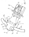
- FIG. 1 shows a perspective view of a steering transmitter 2 designed as a handlebar 1 for an industrial truck designed, for example, as a picker and not shown.
- the handlebar 1 is provided with a flange 3 for attachment to a trained on a driver's platform for the operator parapet of the order picker.
- the handlebar 1 is rotatable about a mitttge axis of rotation 4 and has a central portion 5, on which two to the axis of rotation 4 symmetrically arranged handles 6a, 6b are arranged.
- the handle 6b can in this case be grasped by the operator's left hand and the handle 6a by the right hand of the operator.
- In the middle section 5 of the handlebar 1 further controls of the truck are arranged, for example, the driving speed and the direction of travel predetermining rotary switch 7a, 7b for the traction drive, push button 8a, 8b for the linear actuator and a key switch 9 for a warning device, such as a horn.
- a sensor device 10 the rotational movement of the handlebar 1 for controlling the steering drive of the truck can be detected.
- FIGs 2 and 3 the structure of the handle 6a is shown.
- the handle 6b has an identical structure.
- the arranged in the handle 6a actuator 11a is formed as an operable by the hand of the operator when gripping the handle 6a
- Tastbügel 12 which extends in the longitudinal direction of the handle 6a on the handle portion and the outer region of the handle 6a about a rotation axis thirteenth is arranged pivotally.
- the Tastbügel 12 is provided at the middle portion 5 of the handlebar 1 facing area with an actuator 14 to which a slope 15 is formed.
- the slope 15 is designed as a bracket 16 actuating element 17 of the dead switch 19 formed by an electrical switch 18, which is arranged in the handle 6a.
- a stop surface 21 is formed, which can be brought into operative connection with a stop element 22 in the handle 6a to limit the application of the Tastbügels 12 by the spring element 20.
- the Tastbügel 12 is acted upon by the spring element 20 with unconfirmed actuator 11a, 11b in a switching position in which the unactuated deadman switch 19 generates a signal to act on the braking device and thus to brake the truck.
- the unactuated deadman switch 19 Upon actuation of the Tastbügels 12 by grasping the handle 6a cross the operator's hand of the deadman switch 19 is also actuated, whereby the operation of the braking device is terminated and the drive of the truck is operable.
- each with a arranged in the two handles 6a, 6b and actuated by means of a Tastbügels 12 deadman switch 19 are the two deadman switch 19 with a control device in the following manner in operative connection:
- the drive is at a reduced maximum travel speed operated. If the operator releases the handle 6a or 6b, the actuation of the deadman switch 19 is ended via the spring-loaded feeler bar 12 and the industrial truck is braked.
- an operation of the traction drive of the truck is standing next to the truck or running next to the vehicle operator, the operator with only one hand a handle 6a and 6b surrounds, allows reduced maximum speed.
- both feelers 12 are pressed simultaneously or successively by grasping both handles 6a, 6b with both hands, and thus both deadman switches 19 are actuated, the travel drive can be operated at maximum travel speed.
- both feeler bar 12 By pressing both feeler bar 12, an operation of the truck with maximum driving speed can be made possible in this case when the operator is on the truck.
- the truck is braked by applying the braking device.
Abstract
Description
Die Erfindung betrifft ein Flurförderzeug, insbesondere Kommissionierfahrzeug, mit einem Lenkgeber und einer Totmannbremseinrichtung, die mindestens einen mittels eines Betätigungsorgans betätigbaren Totmannschalter aufweist, der mit einer Bremsvorrichtung des Flurförderzeugs in Wirkverbindung steht.The invention relates to an industrial truck, in particular picking vehicle, with a steering transmitter and a dead man's brake device, which has at least one actuatable by means of an actuator deadman switch, which is in operative connection with a braking device of the truck.
Ein gattungsgemäßes Flurförderzeug ist aus der DE 197 43 735 A1 bekannt. Das als Kommissionierfahrzeug ausgebildete Flurförderzeug weist einen als Lenker ausgebildeten Lenkgeber auf und einen in einer Fahrerstandplattform angeordneten Totmannschalter einer Totmannbremseinrichtung, der von-der Bedienperson mit dem Fuß betätigbar ist. Der Aufbau eines derartigen Totmannschalters ist in der DE 101 03 536 A1 offenbart. Zur Betätigung des Totmannschalters ist hierbei ein in der Fahrerstandplattform schwenkbar angeordnetes, als Betätigungsfläche ausgebildetes Betätigungsorgan vorgesehen. Bei gattungsgemäßen Flurförderzeugen bewirkt ein Loslassen des Betätigungsorgans und somit ein Beenden der Betätigung des Totmannschalters ein Abbremsen des Flurförderzeugs. Bei betätigtem Betätigungsorgan und somit betätigtem Totmannschalter kann der Fahrantrieb des Flurförderzeugs betrieben werden. Die Anordnung des Totmannschalters in der Fahrerstandplattform ergibt jedoch durch die Betätigung des Betätigungsorgans des Totmannschalters durch den Fuß der Bedienperson während des Betriebs des Flurförderzeugs eine eingeschränkte Bewegungsfreiheit der Bedienperson, wodurch sich bei länger andauerndem Betrieb des Flurförderzeugs eine ungünstige Ergonomie ergeben kann. Zudem ist zum Betrieb des Fahrantriebs erforderlich, dass sich die Bedienperson auf der Fahrerstandplattform befindet, um das Betätigungsorgan des Totmannschalters betätigen zu können. Hierdurch ergibt sich jedoch ein häufiges Auf- und Absteigen der Bedienperson im Betrieb des Flurförderzeugs, selbst wenn nur kurze Fahrstrecken von wenigen Metern zu überbrücken sind. Darüber hinaus ergibt sich durch die Anordnung des Totmannschalters in der Fahrerstandplattform und der zur Betätigung des Totmannschalters erforderlichen, in der Fahrerstandplattform schwenkbar gelagerten Betätigungsfläche ein hoher Bauaufwand für das Betätigungsorgan des Totmannschalters.A generic truck is known from DE 197 43 735 A1. Trained as a picking truck truck has a handlebar designed as a steering transmitter and arranged in a driver platform platform deadman switch deadman's brake device, which can be actuated by the operator with his foot. The structure of such deadman switch is disclosed in DE 101 03 536 A1. To actuate the deadman switch here in the operator platform platform pivotally mounted, designed as an actuating surface actuating member is provided. In generic trucks causes a release of the actuator and thus terminating the operation of the deadman switch causes a slowing down of the truck. When actuated actuator and thus actuated deadman switch the traction drive of the truck can be operated. However, the arrangement of the deadman switch in the operator platform results in a limited freedom of movement of the operator by the operation of the actuator of the dead man by the foot of the operator during operation of the truck, which can result in unfavorable ergonomics with prolonged operation of the truck. In addition, to operate the traction drive is required that the operator is on the driver's platform to operate the actuator of the deadman switch can. However, this results in frequent up and dismounting of the operator in the operation of the truck, even if only short distances of a few meters are to be bridged. In addition, results from the arrangement of the deadman switch in the operator platform and required for the actuation of the deadman switch, pivotally mounted in the operator platform actuating surface a high construction cost for the actuator of the deadman switch.
Der vorliegenden Erfindung liegt die Aufgabe zugrunde, ein Flurförderzeug der eingangs genannten Gattung zur Verfügung zu stellen, das bei günstiger Ergonomie einen verbesserten Betrieb des Flurförderzeugs bei einem geringen Bauaufwand für das Betätigungsorgan des Totmannschalters ermöglicht.The present invention has for its object to provide an industrial truck of the type mentioned that allows for improved ergonomics improved operation of the truck at a low construction cost for the actuator of the deadman switch.
Diese Aufgabe wird erfindungsgemäß dadurch gelöst, dass das Betätigungsorgan des Totmannschalters im Lenkgeber angeordnet ist. Durch eine Anordnung und somit Integration des Betätigungsorgan des Totmannschalters der Totmannbremseinrichtung in den Lenkgeber kann im Betrieb des Flurförderzeugs eine hohe Bewegungsfreiheit der Bedienperson und somit eine günstige Ergonomie erzielt werden. Zudem kann durch die Anordnung des Betätigungsorgans des Totmannschalters im Lenkgeber ein Betrieb des Fahrantriebs des Flurförderzeugs ermöglicht werden, wenn sich die Bedienperson neben dem Flurförderzeug befindet und die Bedienperson das Betätigungsorgan nd somit den Totmannschalter am Lenkgeber betätigt. Das Flurförderzeug kann somit - ohne dass die Bedienperson zur Betätigung des Betätigungsorgans des Totmannschalters und somit zur Betätigung des Fahrantriebs auf das Flurförderzeug auf- und absteigen muss - über kurze Fahrstrecken betrieben werden. Insbesondere bei Kommissionierfahrzeugen, bei denen im Betrieb häufig kurze Fahrstecken auftreten, ergibt sich somit ein verbesserter Betrieb des Flurförderzeugs. Darüber hinaus weist ein im Lenkgeber integriertes Betätigungsorgan des Totmannschalters gegenüber einem in der Fahrerstandplattform gelenkig gelagerten, als Betätigungsfläche ausgebildeten Betätigungsorgans einen verringerten Bauaufwand auf.This object is achieved in that the actuator of the dead man's switch is arranged in the steering transmitter. By arranging and thus integrating the actuating member of the deadman switch of the deadman brake device in the steering transmitter, a high freedom of movement of the operator and thus a favorable ergonomics can be achieved during operation of the truck. In addition, can be made possible by the arrangement of the actuator of the deadman switch in the steering transmitter operation of the drive of the truck when the operator is located next to the truck and the operator actuates the actuator thus nd the deadman switch on the steering transmitter. The truck can thus - without the operator to operate the actuator of the deadman switch and thus to operate the traction drive on the truck and dismount - are operated over short distances. In particular, in order picking vehicles in which often occur short driving in operation, thus resulting in improved operation of the truck. In addition, an integrated in the steering actuator actuator of Totmannschalters compared to an articulated in the operator platform platform, designed as an actuating surface actuator a reduced construction costs.
Gemäß einer bevorzugten Ausführungsform der Erfindung, bei der der Lenkgeber mindestens einen Handgriff aufweist, ergeben sich besondere Vorteile, wenn das Betätigungsorgan des Lenkgebers im Handgriff des Lenkgebers angeordnet ist. Das Betätigungsorgan des Totmannschalters kann in dem Handgriff des Lenkgebers mit geringem Bauaufwand angeordnet werden. Zudem ist hierbei das Betätigungsorgan und somit der Totmannschalter durch Umgreifen des Handgriffs des Lenkgebers von der Bedienperson betätigbar, wodurch ein Betrieb des Fahrantriebs des Flurförderzeugs bei günstiger Ergonomie zur Betätigung des Betätigungsorgans für die Bedienperson erzielbar ist.According to a preferred embodiment of the invention, in which the steering transmitter has at least one handle, there are particular advantages when the actuating member of the steering transmitter is arranged in the handle of the steering transmitter. The actuator of the deadman switch can be arranged in the handle of the steering transmitter with low construction costs. In addition, in this case, the actuator and thus the dead man's switch by gripping the handle of the steering transmitter of the operator actuated, whereby operation of the drive of the truck with a favorable ergonomics for actuating the actuator for the operator can be achieved.
Der Totmannschalter kann am Lenkgeber getrennt von dem Handgriff angeordnet sein. Besondere Vorteile ergeben sich, wenn der Totmannschalter im Handgriff des Lenkgebers angeordnet ist. Durch die Integration des Totmannschalters und des Betätigungsorgans des Totmannschalters in den Handgriff des Lenkgebers kann ein einfacher Aufbau mit geringem Bauaufwand erzielt werden und der Bauraum des Lenkgebers neben dem Handgriff zur Anordnung weiterer Bedienelemente des Flurförderzeugs genutzt werden, beispielsweise eines Drehschalters für den Fahrantrieb oder eines Tastschalters für den Hubantrieb des Flurförderzeugs.The deadman switch can be arranged separately from the handle on the steering transmitter. Particular advantages arise when the deadman switch is arranged in the handle of the steering transmitter. By integrating the deadman switch and the actuator of the dead man's switch in the handle of the steering sensor a simple structure with low construction costs can be achieved and the space of the steering transmitter in addition to the handle for the arrangement of further controls of the truck can be used, such as a rotary switch for the drive or a pushbutton for the lifting drive of the truck.
Gemäß einer bevorzugten Ausführungsform der Erfindung ist das Betätigungsorgan als in dem Handgriff angeordneter Tastbügel ausgebildet ist. Mit einem als Tastbügel ausgebildetes Betätigungsorgan des Totmannschalters kann von der Bedienperson auf einfache Weise durch ein Umgreifen der den Handgriff greifenden Hand eine ergonomische Betätigung des Betätigungsorgans und somit des Totmannschalters erzielt werden, um einen Betrieb des Fahrantriebs zu ermöglichen.According to a preferred embodiment of the invention, the actuating member is designed as arranged in the handle Tastbügel. With a trained as a feeler actuator of the deadman switch can be achieved by the operator in a simple manner by grasping the hand gripping the hand ergonomic actuation of the actuator and thus the deadman switch to allow operation of the traction drive.
Eine vorteilhafte Ausgestaltungsform der Erfindung sieht vor, dass der Totmannschalter als ein mittels eines Betätigungselements betätigbarer elektrischer Schalter ausgebildet ist, wobei das Betätigungsorgan mit einer das Betätigungselement betätigbaren Betätigungseinrichtung versehen ist. Durch diese Bauweise kann mit dem Betätigungsorgan auf einfache Weise der Totmannschalter betätigt werden.An advantageous embodiment of the invention provides that the deadman switch is designed as an actuatable by means of an actuator electrical switch, wherein the actuating member is provided with an actuating element operable actuation device. By this construction can be operated with the actuator in a simple way, the deadman switch.
Zweckmäßigerweise ist hierbei das Betätigungselement des elektrischen Schalters als Bügel und die Betätigungseinrichtung als an dem Betätigungsorgan angeordnete Schräge ausgebildet. Das als Tastbügel ausgebildete Betätigungsorgan kann auf einfache Weise mit einer Schräge versehen werden, die eine Betätigung des Bügels des Totmannschalters ermöglicht, wodurch sich ein geringer Bauaufwand ergibt.Conveniently, in this case, the actuating element of the electrical switch as a bracket and the actuating device is designed as arranged on the actuator bevel. Trained as Tastbügel actuator can be easily provided with a slope that allows actuation of the bracket of the deadman switch, resulting in a low construction cost.
Gemäß einer bevorzugten Weiterbildung der Erfindung ist im Handgriff ein mit dem Betätigungsorgan in Wirkverbindung stehendes Federelement angeordnet ist, das einer Betätigung des Betätigungsorgans entgegenwirkt. Beim Loslassen des Handgriffes wird somit sichergestellt, dass das Betätigungsorgan durch das Federelement in eine Stellung beaufschlagt wird, in der mittels des unbetätigten Totmannschalters ein Abbremsen des Flurförderzeugs erzielt wird.According to a preferred embodiment of the invention, a standing with the actuator in operative connection spring element is arranged in the handle, which counteracts an actuation of the actuating member. When you release the handle is thus ensured that the actuator is acted upon by the spring element in a position in which a deceleration of the truck is achieved by means of the unactuated deadman switch.
Besondere Vorteile ergeben sich, wenn gemäß einer vorteilhaften Weiterbildung der Erfindung die Totmannbremseinrichtung zwei Totmannschalter aufweist, wobei in dem Lenkgeber für jeden Totmannschalter ein Betätigungsorgan angeordnet ist. Durch die Anordnung von zwei mittels jeweils eines Betätigungsorgans betätigbarer Totmannschalter im Lenkgeber kann ein weiter verbesserter Betrieb des Flurförderzeugs durch eine Steuerung des Fahrantriebs in Abhängigkeit von der Betätigung der beiden Totmannschalter erzielt werden.Particular advantages arise when according to an advantageous embodiment of the invention, the dead man's brake device has two deadman switch, wherein in the steering transmitter for each deadman switch an actuator is arranged. By arranging two operable by means of an actuator deadman switch in the steering sensor, a further improved operation of the truck can be achieved by controlling the traction drive in response to the operation of the two deadman switch.
Der Lenkgeber kann hierbei als Deichsel ausgebildet sein. Gemäß einer bevorzugten Ausführungsform der Erfindung ist der Lenkgeber als drehbarer Lenker ausgebildet, der zwei bezüglich einer Drehachse des Lenkgebers im wesentlichen symmetrisch angeordnete Handgriffe aufweist, wobei in jedem Handgriff ein Betätigungsorgan eines Totmannschalters angeordnet ist. Ein derartiger als Lenker mit zwei Handgriffen ausgebildeter Lenkgeber eines Flurförderzeugs ist in der DE 196 15 168 A1 offenbart und ermöglicht eine ergonomische Bedienung eines als Kommissionierer ausgebildeten Flurförderzeugs. Durch jeweils ein in einem Handgriff angeordnetes Betätigungsorgan ist hierbei auf ergonomisch günstige Weise eine Betätigung der beiden Totmannschalter erzielbar.The steering transmitter can be designed here as a drawbar. According to a preferred embodiment of the invention, the steering transmitter is designed as a rotatable link which has two with respect to a rotational axis of the steering transmitter substantially symmetrically arranged handles, wherein in each handle an actuator of a deadman switch is arranged. Such as a handlebar with two handles trained steering sensor of a truck is disclosed in DE 196 15 168 A1 and allows ergonomic operation of a trained as a picker truck. By one arranged in a handle actuator in this case, an operation of the two deadman is achievable ergonomically favorable manner.
Sofern hierbei gemäß einer bevorzugten Ausführungsform der Erfindung die Totmannschalter mit einer Steuereinrichtung in Wirkverbindung stehen, kann ein verbesserter Betrieb des Flurförderzeugs erzielt werden, wenn bei Betätigung eines Betätigungsorgans mittels der Steuereinrichtung der Fahrantrieb mit einer reduzierten maximalen Fahrgeschwindigkeit betreibbar ist. Sofern sich die Bedienperson neben dem Flurförderzeug befindet und lediglich ein Betätigungsorgan und somit einen Totmannschalter durch Umgreifen eines Handgriffes des Lenkers betätigt, kann der Fahrantrieb mit einer reduzierten maximalen Fahrgeschwindigkeit betrieben werden, so dass ein Betrieb des Flurförderzeugs bei einer neben dem Flurförderzeug stehenden oder laufenden Bedienperson mit reduzierter maximaler Fahrgeschwindigkeit ermöglicht wird. Durch die reduzierte maximale Fahrgeschwindigkeit wird in einem derartigen Betriebszustand ein sicherer Betrieb des Flurförderzeugs sichergestelltIf, according to a preferred embodiment of the invention, the dead man's switch are operatively connected to a control device, improved operation of the industrial truck can be achieved if the travel drive can be operated at a reduced maximum driving speed when an actuating member is actuated by means of the control device. If the operator is located next to the truck and only actuates an actuator and thus a dead man's switch by grasping a handle of the handlebar, the drive can be operated at a reduced maximum travel speed, so that operation of the truck in a standing next to the truck or ongoing operator is made possible with reduced maximum driving speed. Due to the reduced maximum driving speed, safe operation of the truck is ensured in such an operating state
Gemäß einer bevorzugten Weiterbildung ist hierbei bei der Betätigung beider Betätigungsorgane mittels der Steuereinrichtung der Fahrantrieb mit einer maximalen Fahrgeschwindigkeit betreibbar ist. Bei einer gleichzeitigen oder nacheinander erfolgenden Betätigung beider Betätigungsorgane und somit beider Totmannschalter durch Umgreifen beider Handgriffe des Lenkers kann das Vorhandensein der Bedienperson auf dem Flurförderzeug, beispielsweise auf einer Fahrerstandplattform, auf einfache Weise ermittelt werden und somit der Betrieb des Flurförderzeugs mit der maximalen Fahrgeschwindigkeit zugelassen werden.According to a preferred refinement, the traction drive can be operated at a maximum driving speed when the two actuators are actuated by means of the control device. In a simultaneous or successive Successful actuation of both actuators and thus both deadman by grasping both handles of the handlebar, the presence of the operator on the truck, for example on a driver's platform, can be determined in a simple manner and thus the operation of the truck are allowed at the maximum speed.
Sofern hierbei gemäß einer bevorzugten Weiterbildung der Erfindung bei der Betätigung beider Betätigungsorgane und anschließendem Loslassen eines Betätigungsorgans mittels der Steuereinrichtung der Fahrantrieb mit der maximalen Fahrgeschwindigkeit betreibbar bleibt, wird verhindert, dass das Flurförderzeug in einem Betriebszustand, bei dem sich die Bedienperson auf dem Flurförderzeug befindet und beide Betätigungsorgane betätigt, durch das anschließende Loslassen eines Handgriffes und somit dem Beenden der Betätigung eines Betätigungsorgans und somit dem Beenden der Betätigung eines Totmannschalters ein Abbremsen des Flurförderzeugs auf die reduzierte maximale Fahrgeschwindigkeit erfolgt. Hierdurch wird erzielt, dass das Flurförderzeug mit der maximalen Fahrgeschwindigkeit betreibbar bleibt, wenn sich die Bedienperson auf dem Flurförderzeug befindet und nach der Betätigung beider Betätigungsorgane eine Hand von einem Handgriff des Lenkgebers nimmt. Es wird somit ermöglicht, dass die auf dem Flurförderzeug befindliche Bedienperson eine Hand frei hat, um weitere Bedienungsfunktionen auszuführen, wobei das Flurförderzeug mit der maximalen Fahrgeschwindigkeit betreibbar bleibt.If according to a preferred embodiment of the invention in the operation of both actuators and subsequent release of an actuator by means of the control device of the drive at the maximum driving speed remains operable, prevents the truck in an operating condition in which the operator is on the truck and actuates both actuators, by the subsequent letting go of a handle and thus the termination of the operation of an actuator and thus terminating the operation of a deadman switch, a deceleration of the truck takes place on the reduced maximum travel speed. This ensures that the truck remains operable at the maximum driving speed when the operator is on the truck and takes a hand of a handle of the steering transmitter after the actuation of both actuators. It is thus possible that the operator located on the truck has a hand free to carry out further operating functions, the truck remains operable at the maximum driving speed.
In zweckmäßiger Weiterbildung der Erfindung ist vorgesehen, dass beim Loslassen beider Betätigungsorgane mittels der Steuereinrichtung die Bremsvorrichtung zum Abbremsen des Flurförderzeugs betätigbar ist. Hierdurch wird auf einfache Weise sichergestellt, dass beim Loslassen beider Betätigungsorgane und somit beider Handgriffe mittels der unbetätigten Totmannschalter ein Abbremsen des Flurförderzeugs erzielt wird.In an advantageous embodiment of the invention, it is provided that when releasing both actuators by means of the control device, the braking device for braking the truck is actuated. This ensures in a simple manner that when releasing both actuators and thus both handles by means of the unmanned deadman switch a deceleration of the truck is achieved.
Weitere Vorteile und Einzelheiten der Erfindung werden anhand des in den schematischen Figuren dargestellten Ausführungsbeispiels näher erläutert. Hierbei zeigt
- Figur 1
- eine perspektivische Darstellung eines als Lenker ausgebildeten Lenkgebers eines erfindungsgemäßen Flurförderzeugs,
Figur 2- den Schnitt durch einen Handgriff des Lenkers und
Figur 3- den Schnitt gemäß der
Figur 2 in einer vergrößerten Darstellung.
- FIG. 1
- a perspective view of a trained as a steering arm of a truck according to the invention,
- FIG. 2
- the cut by a handle of the handlebar and
- FIG. 3
- the section according to the figure 2 in an enlarged view.
In der Figur 1 ist eine perspektivische Darstellung eines als Lenker 1 ausgebildeten Lenkgebers 2 für ein beispielsweise als Kommissionierer ausgebildetes und nicht mehr dargestelltes Flurförderzeug dargestellt. Der Lenker 1 ist mit einem Flansch 3 zur Befestigung an einer an einer Fahrerstandplattform für die Bedienperson ausgebildeten Brüstung des Kommissionierers versehen.FIG. 1 shows a perspective view of a
Der Lenker 1 ist um eine mitttge Drehachse 4 drehbar und weist einen mittleren Abschnitt 5 auf, an dem zwei zur Drehachse 4 symmetrisch angeordnete Handgriffe 6a, 6b angeordnet sind. Der Handgriff 6b kann hierbei von der linken Hand der Bedienperson und der Handgriff 6a von der rechten Hand der Bedienperson umgriffen werden. In dem mittleren Abschnitt 5 des Lenkers 1 sind weitere Bedienelemente des Flurförderzeugs angeordnet, beispielsweise die Fahrgeschwindigkeit und die Fahrtrichtung vorgebende Drehschalter 7a, 7b für den Fahrantriebs, Tastschalter 8a, 8b für den Hubantrieb und ein Tastschalter 9 für ein Warneinrichtung, beispielsweise eine Hupe. Mittels einer Sensoreinrichtung 10 ist die Drehbewegung des Lenkers 1 zur Steuerung des Lenkantriebs des Flurförderzeugs erfassbar.The handlebar 1 is rotatable about a mitttge axis of
Erfindungsgemäß ist im Lenkgeber 2 in den Handgriffen 6a, 6b des Lenkers 1 im Griffbereich der den Handgriff umgreifenden Hand der Bedienperson jeweils ein Betätigungsorgan 11a, 11 b eines Totmannschalters angeordnet.According to the invention in the
In den Figuren 2 und 3 ist der Aufbau des Handgriffes 6a dargestellt. Der Handgriff 6b weist einen identischen Aufbau auf.In Figures 2 and 3, the structure of the handle 6a is shown. The handle 6b has an identical structure.
Das in dem Handgriff 6a angeordnete Betätigungsorgan 11a ist als ein von der Hand der Bedienperson beim Umgreifen des Handgriffs 6a betätigbarer Tastbügel 12 ausgebildet, der sich in Längsrichtung des Handgriffes 6a über den Griffbereich erstreckt und am äußeren Bereich des Handgriffes 6a um eine Drehachse 13 schwenkbar angeordnet ist. Der Tastbügel 12 ist an dem dem mittleren Abschnitt 5 der Lenkers 1 zugewandten Bereich mit einer Betätigungseinrichtung 14 versehen, an der eine Schräge 15 ausgebildet ist. Mittels der Schräge 15 ist ein als Bügel 16 ausgebildetes Betätigungselement 17 des von einem elektrischen Schalter 18 gebildeten Totmannschalters 19 betätigbar, der im Handgriff 6a angeordnet ist.The arranged in the handle 6a actuator 11a is formed as an operable by the hand of the operator when gripping the
In dem Handgriff 6a ist weiterhin ein als Bügelfeder 23 ausgebildetes Federelement 20 angeordnet, das mit dem Tastbügel 12 in Wirkverbindung steht und der Betätigung des Tastbügels 12 durch die Hand der Bedienperson entgegenwirkt.In the handle 6a further designed as a
An dem Betätigungselement 14 des Tastbügels 12 ist gegenüberliegend zur Schräge 15 eine Anschlagfläche 21 ausgebildet, die mit einem Anschlagelement 22 im Handgriff 6a in Wirkverbindung bringbar ist, um die Beaufschlagung des Tastbügels 12 durch das Federelement 20 zu begrenzen.On the
Der Tastbügel 12 wird durch das Federelement 20 bei unbetätigtem Betätigungsorgan 11a, 11b in eine Schaltstellung beaufschlagt, in der der unbetätigte Totmannschalter 19 ein Signal zur Beaufschlagung der Bremsvorrichtung und somit zum Abbremsen des Flurförderzeugs erzeugt. Bei einer Betätigung des Tastbügels 12 durch ein Umgreifen der den Handgriff 6a greifenden Hand der Bedienperson wird der Totmannschalter 19 ebenfalls betätigt, wodurch die Betätigung der Bremsvorrichtung beendet wird und der Fahrantrieb des Flurförderzeugs betreibbar ist.The
Bei einem erfindungsgemäßen Lenker 1 mit jeweils einem in den beiden Handgriffen 6a, 6b angeordneten und mittels jeweils eines Tastbügels 12 betätigbaren Totmannschalters 19 stehen die beiden Totmannschalter 19 mit einer Steuereinrichtung in folgender Weise in Wirkverbindung:In a handlebar 1 according to the invention, each with a arranged in the two handles 6a, 6b and actuated by means of a
Bei losgelassenen Handgriffen 6a, 6b und somit bei nicht betätigten Tastbügeln 12 ist durch die Signale der unbetätigten Totmannschalter mittels der Steuereinrichtung die Bremsvorrichtung zum Abbremsen des Flurförderzeugs beaufschlagt.When released handles 6a, 6b and thus with
Wird ausgehend hiervon von der Bedienperson durch Umgreifen eines Handgriffes 6a bzw. 6b mit einer Hand lediglich ein Tastbügel 12 und somit ein Totmannschalter 19 betätigt, ist der Fahrantrieb mit einer reduzierten maximalen Fahrgeschwindigkeit betreibbar. Lässt die Bedienperson den Handgriff 6a bzw. 6b los, wird über den federbeaufschlagten Tastbügel 12 die Betätigung des Totmannschalters 19 beendet und das Flurförderzeug abgebremst. Somit ist ein Betrieb des Fahrantriebs des Flurförderzeugs bei neben dem Flurförderzeug stehender bzw. neben dem Fahrzeug laufender Bedienperson, wobei die Bedienperson lediglich mit einer Hand einen Handgriff 6a bzw. 6b umgreift, mit reduzierter maximaler Fahrgeschwindigkeit ermöglicht.If, starting from this, the operator actuates merely one
Werden beide Tastbügel 12 gleichzeitig oder nacheinander durch Umgreifen beider Handgriff 6a, 6b mit beiden Händen gedrückt und somit beide Totmannschalter 19 betätigt, ist der Fahrantrieb mit maximaler Fahrgeschwindigkeit betreibbar. Durch das Betätigen beider Tastbügel 12 kann hierbei bei auf dem Flurförderzeug befindlicher Bedienperson ein Betrieb des Flurförderzeugs mit maximaler Fahrgeschwindigkeit ermöglicht werden.If both
Lässt die Bedienperson hierbei einen Handgriff 6a bzw. 6b los und wird somit über den zugeordneten federbeaufschlagten Tastbügel 12 die Betätigung eines Totmannschalters 19 beendet, bleibt der Betrieb des Fahrantriebs mit maximaler Fahrgeschwindigkeit erhalten. Die auf dem Flurförderzeug befindliche Bedienperson kann somit eine Hand von dem Lenker 1 nehmen, um weitere Bedienfunktionen zu betätigen, wobei das Flurförderzeug mit maximaler Fahrgeschwindigkeit betreibbar bleibt.If the operator releases a handle 6a or 6b in this case and thus the actuation of a
Nimmt die Bedienperson weiterhin die zweite Hand von dem Lenker 1 und wird somit durch Loslassen des zweiten Tastbügels 12 weiterhin die Betätigung des zweiten Totmannschalters 19 beendet, wird das Flurförderzeug durch Beaufschlagung der Bremsvorrichtung abgebremst.If the operator continues to take the second hand from the handlebar 1 and thus the actuation of the
Claims (13)
Applications Claiming Priority (1)
| Application Number | Priority Date | Filing Date | Title |
|---|---|---|---|
| DE102005006855A DE102005006855A1 (en) | 2005-02-15 | 2005-02-15 | Industrial truck with a steering transmitter |
Publications (2)
| Publication Number | Publication Date |
|---|---|
| EP1690820A1 true EP1690820A1 (en) | 2006-08-16 |
| EP1690820B1 EP1690820B1 (en) | 2011-07-27 |
Family
ID=36217495
Family Applications (1)
| Application Number | Title | Priority Date | Filing Date |
|---|---|---|---|
| EP06002759A Not-in-force EP1690820B1 (en) | 2005-02-15 | 2006-02-10 | Industrial truck comprising a steering |
Country Status (4)
| Country | Link |
|---|---|
| EP (1) | EP1690820B1 (en) |
| AT (1) | ATE517839T1 (en) |
| DE (1) | DE102005006855A1 (en) |
| ES (1) | ES2368935T3 (en) |
Cited By (5)
| Publication number | Priority date | Publication date | Assignee | Title |
|---|---|---|---|---|
| EP2148346A1 (en) | 2008-07-25 | 2010-01-27 | Alstom Transport S.A. | Vehicle steering control |
| US10252683B2 (en) | 2016-02-09 | 2019-04-09 | Crown Equipment Corporation | Mounting bar assembly for a materials handling vehicle |
| USD856628S1 (en) | 2017-04-03 | 2019-08-13 | Crown Equipment Corporation | Mounting bar assembly |
| CN111716359A (en) * | 2020-06-30 | 2020-09-29 | 福州大学 | Composite navigation type differential storage robot and working method thereof |
| US11866310B2 (en) | 2021-01-29 | 2024-01-09 | Crown Equipment Corporation | Work assist system for an industrial vehicle |
Families Citing this family (1)
| Publication number | Priority date | Publication date | Assignee | Title |
|---|---|---|---|---|
| EP2351891A1 (en) | 2010-01-11 | 2011-08-03 | Armacell Enterprise GmbH | Insulation material with mechanical strength and building elements and composites made thereof |
Citations (6)
| Publication number | Priority date | Publication date | Assignee | Title |
|---|---|---|---|---|
| GB599585A (en) * | 1945-09-19 | 1948-03-16 | Gen Electric Co Ltd | Improvements in or relating to electric trolley buses |
| US5112184A (en) * | 1990-06-11 | 1992-05-12 | Reach All | Multi-function hydraulic control handle |
| DE19732511A1 (en) * | 1996-07-30 | 1998-03-05 | Raymond Corp | Movement control system for a material transport trolley |
| DE19651168A1 (en) | 1996-12-10 | 1998-06-25 | Henn Gmbh & Co Kg | Detent device for push-fit connection between hose and pipe |
| DE19743735A1 (en) | 1997-10-02 | 1999-04-08 | Linde Ag | Floor conveyor, especially commissioner, with driver-stand and dead man's switch |
| DE10103536A1 (en) | 2001-01-26 | 2002-08-01 | Still Wagner Gmbh & Co Kg | Dead man's switch for fork lift trolley, forces switch button to specified safe position when operator does not press pedal |
-
2005
- 2005-02-15 DE DE102005006855A patent/DE102005006855A1/en not_active Withdrawn
-
2006
- 2006-02-10 AT AT06002759T patent/ATE517839T1/en active
- 2006-02-10 EP EP06002759A patent/EP1690820B1/en not_active Not-in-force
- 2006-02-10 ES ES06002759T patent/ES2368935T3/en active Active
Patent Citations (6)
| Publication number | Priority date | Publication date | Assignee | Title |
|---|---|---|---|---|
| GB599585A (en) * | 1945-09-19 | 1948-03-16 | Gen Electric Co Ltd | Improvements in or relating to electric trolley buses |
| US5112184A (en) * | 1990-06-11 | 1992-05-12 | Reach All | Multi-function hydraulic control handle |
| DE19732511A1 (en) * | 1996-07-30 | 1998-03-05 | Raymond Corp | Movement control system for a material transport trolley |
| DE19651168A1 (en) | 1996-12-10 | 1998-06-25 | Henn Gmbh & Co Kg | Detent device for push-fit connection between hose and pipe |
| DE19743735A1 (en) | 1997-10-02 | 1999-04-08 | Linde Ag | Floor conveyor, especially commissioner, with driver-stand and dead man's switch |
| DE10103536A1 (en) | 2001-01-26 | 2002-08-01 | Still Wagner Gmbh & Co Kg | Dead man's switch for fork lift trolley, forces switch button to specified safe position when operator does not press pedal |
Cited By (7)
| Publication number | Priority date | Publication date | Assignee | Title |
|---|---|---|---|---|
| EP2148346A1 (en) | 2008-07-25 | 2010-01-27 | Alstom Transport S.A. | Vehicle steering control |
| US8172028B2 (en) | 2008-07-25 | 2012-05-08 | Alstrom Transport Sa | Vehicle driving control |
| RU2536422C2 (en) * | 2008-07-25 | 2014-12-20 | Альстом Транспорт Са | Vehicle control manipulator |
| US10252683B2 (en) | 2016-02-09 | 2019-04-09 | Crown Equipment Corporation | Mounting bar assembly for a materials handling vehicle |
| USD856628S1 (en) | 2017-04-03 | 2019-08-13 | Crown Equipment Corporation | Mounting bar assembly |
| CN111716359A (en) * | 2020-06-30 | 2020-09-29 | 福州大学 | Composite navigation type differential storage robot and working method thereof |
| US11866310B2 (en) | 2021-01-29 | 2024-01-09 | Crown Equipment Corporation | Work assist system for an industrial vehicle |
Also Published As
| Publication number | Publication date |
|---|---|
| EP1690820B1 (en) | 2011-07-27 |
| ATE517839T1 (en) | 2011-08-15 |
| DE102005006855A1 (en) | 2006-08-17 |
| ES2368935T3 (en) | 2011-11-23 |
Similar Documents
| Publication | Publication Date | Title |
|---|---|---|
| EP1632426B1 (en) | Drawbar for a forklift truck | |
| EP1690820B1 (en) | Industrial truck comprising a steering | |
| DE19625498C1 (en) | Steering device for controlling longitudinal and cross movement of road vehicle | |
| DE19625501C2 (en) | Control element arrangement for controlling the longitudinal and transverse movement of a motor vehicle | |
| EP3320164B1 (en) | Securing device for front hoods, comprising an electric drive | |
| DE19625500C2 (en) | Control element arrangement for controlling the longitudinal and transverse movement of a motor vehicle | |
| EP1155939B1 (en) | Steering wheel for an industrial truck | |
| DE102009027871A1 (en) | Hand tool | |
| DE19625497C1 (en) | Operating element arrangement for control of longitudinal and transverse movement of motor vehicle | |
| WO2013092029A2 (en) | Power tool | |
| DE19615168B4 (en) | Low-level order picker with a steering control for a standing driver | |
| DE102004040975A1 (en) | Steering wheel for mobile work machine e.g. industrial truck, has operating units, sensor unit and feedback unit integrated in knob of steering wheel, where sensor unit detects presence of operating person in mobile work machine | |
| EP2138445B1 (en) | Operating console for an industrial truck | |
| DE102008060712A1 (en) | Truck | |
| DE19601694A1 (en) | Manual control column for fork-lift pallet trolley | |
| DE19625496A1 (en) | Control element arrangement for controlling the longitudinal and / or transverse movement of a motor vehicle | |
| DE102015111554B4 (en) | LEVER SWITCH OF A SADDLE TYPE VEHICLE | |
| DE19839203C2 (en) | Safety device for hand-held tools with motor drive | |
| DE60308119T2 (en) | Tiller-controlled industrial truck and control method for such a vehicle | |
| DE102019009040A1 (en) | vehicle | |
| DE4307932A1 (en) | Steering-handle arrangement on a vehicle, in particular on a vehicle for a disabled person | |
| EP1415875A2 (en) | Brake actuator | |
| DE102009013116A1 (en) | Brake operating device for use in working machine i.e. industrial truck, has adjusting device for adjusting steering wheel operating unit and staying in effective-connection with brake, where operating unit has adjustable steering wheel | |
| EP2851247B1 (en) | Actuation device for a brake | |
| DE10230586A1 (en) | Door lock for a motor vehicle comprises a control nut and a lock nut mechanically coupled together with an empty run, and a drive unit released within the empty run to lock/unlock the door lock on operation of the control nut |
Legal Events
| Date | Code | Title | Description |
|---|---|---|---|
| PUAI | Public reference made under article 153(3) epc to a published international application that has entered the european phase |
Free format text: ORIGINAL CODE: 0009012 |
|
| AK | Designated contracting states |
Kind code of ref document: A1 Designated state(s): AT BE BG CH CY CZ DE DK EE ES FI FR GB GR HU IE IS IT LI LT LU LV MC NL PL PT RO SE SI SK TR |
|
| AX | Request for extension of the european patent |
Extension state: AL BA HR MK YU |
|
| 17P | Request for examination filed |
Effective date: 20070116 |
|
| 17Q | First examination report despatched |
Effective date: 20070216 |
|
| AKX | Designation fees paid |
Designated state(s): AT BE BG CH CY CZ DE DK EE ES FI FR GB GR HU IE IS IT LI LT LU LV MC NL PL PT RO SE SI SK TR |
|
| GRAP | Despatch of communication of intention to grant a patent |
Free format text: ORIGINAL CODE: EPIDOSNIGR1 |
|
| GRAS | Grant fee paid |
Free format text: ORIGINAL CODE: EPIDOSNIGR3 |
|
| GRAA | (expected) grant |
Free format text: ORIGINAL CODE: 0009210 |
|
| AK | Designated contracting states |
Kind code of ref document: B1 Designated state(s): AT BE BG CH CY CZ DE DK EE ES FI FR GB GR HU IE IS IT LI LT LU LV MC NL PL PT RO SE SI SK TR |
|
| REG | Reference to a national code |
Ref country code: GB Ref legal event code: FG4D Free format text: NOT ENGLISH |
|
| REG | Reference to a national code |
Ref country code: CH Ref legal event code: EP |
|
| REG | Reference to a national code |
Ref country code: DE Ref legal event code: R096 Ref document number: 502006009879 Country of ref document: DE Effective date: 20110915 |
|
| REG | Reference to a national code |
Ref country code: SE Ref legal event code: TRGR |
|
| REG | Reference to a national code |
Ref country code: NL Ref legal event code: VDEP Effective date: 20110727 |
|
| REG | Reference to a national code |
Ref country code: ES Ref legal event code: FG2A Ref document number: 2368935 Country of ref document: ES Kind code of ref document: T3 Effective date: 20111123 |
|
| PG25 | Lapsed in a contracting state [announced via postgrant information from national office to epo] |
Ref country code: NL Free format text: LAPSE BECAUSE OF FAILURE TO SUBMIT A TRANSLATION OF THE DESCRIPTION OR TO PAY THE FEE WITHIN THE PRESCRIBED TIME-LIMIT Effective date: 20110727 Ref country code: LT Free format text: LAPSE BECAUSE OF FAILURE TO SUBMIT A TRANSLATION OF THE DESCRIPTION OR TO PAY THE FEE WITHIN THE PRESCRIBED TIME-LIMIT Effective date: 20110727 Ref country code: PT Free format text: LAPSE BECAUSE OF FAILURE TO SUBMIT A TRANSLATION OF THE DESCRIPTION OR TO PAY THE FEE WITHIN THE PRESCRIBED TIME-LIMIT Effective date: 20111128 Ref country code: FI Free format text: LAPSE BECAUSE OF FAILURE TO SUBMIT A TRANSLATION OF THE DESCRIPTION OR TO PAY THE FEE WITHIN THE PRESCRIBED TIME-LIMIT Effective date: 20110727 Ref country code: IS Free format text: LAPSE BECAUSE OF FAILURE TO SUBMIT A TRANSLATION OF THE DESCRIPTION OR TO PAY THE FEE WITHIN THE PRESCRIBED TIME-LIMIT Effective date: 20111127 |
|
| PG25 | Lapsed in a contracting state [announced via postgrant information from national office to epo] |
Ref country code: CY Free format text: LAPSE BECAUSE OF FAILURE TO SUBMIT A TRANSLATION OF THE DESCRIPTION OR TO PAY THE FEE WITHIN THE PRESCRIBED TIME-LIMIT Effective date: 20110727 Ref country code: LV Free format text: LAPSE BECAUSE OF FAILURE TO SUBMIT A TRANSLATION OF THE DESCRIPTION OR TO PAY THE FEE WITHIN THE PRESCRIBED TIME-LIMIT Effective date: 20110727 Ref country code: GR Free format text: LAPSE BECAUSE OF FAILURE TO SUBMIT A TRANSLATION OF THE DESCRIPTION OR TO PAY THE FEE WITHIN THE PRESCRIBED TIME-LIMIT Effective date: 20111028 Ref country code: SI Free format text: LAPSE BECAUSE OF FAILURE TO SUBMIT A TRANSLATION OF THE DESCRIPTION OR TO PAY THE FEE WITHIN THE PRESCRIBED TIME-LIMIT Effective date: 20110727 Ref country code: PL Free format text: LAPSE BECAUSE OF FAILURE TO SUBMIT A TRANSLATION OF THE DESCRIPTION OR TO PAY THE FEE WITHIN THE PRESCRIBED TIME-LIMIT Effective date: 20110727 |
|
| REG | Reference to a national code |
Ref country code: IE Ref legal event code: FD4D |
|
| PG25 | Lapsed in a contracting state [announced via postgrant information from national office to epo] |
Ref country code: IE Free format text: LAPSE BECAUSE OF FAILURE TO SUBMIT A TRANSLATION OF THE DESCRIPTION OR TO PAY THE FEE WITHIN THE PRESCRIBED TIME-LIMIT Effective date: 20110727 Ref country code: CZ Free format text: LAPSE BECAUSE OF FAILURE TO SUBMIT A TRANSLATION OF THE DESCRIPTION OR TO PAY THE FEE WITHIN THE PRESCRIBED TIME-LIMIT Effective date: 20110727 Ref country code: SK Free format text: LAPSE BECAUSE OF FAILURE TO SUBMIT A TRANSLATION OF THE DESCRIPTION OR TO PAY THE FEE WITHIN THE PRESCRIBED TIME-LIMIT Effective date: 20110727 |
|
| PG25 | Lapsed in a contracting state [announced via postgrant information from national office to epo] |
Ref country code: RO Free format text: LAPSE BECAUSE OF FAILURE TO SUBMIT A TRANSLATION OF THE DESCRIPTION OR TO PAY THE FEE WITHIN THE PRESCRIBED TIME-LIMIT Effective date: 20110727 Ref country code: EE Free format text: LAPSE BECAUSE OF FAILURE TO SUBMIT A TRANSLATION OF THE DESCRIPTION OR TO PAY THE FEE WITHIN THE PRESCRIBED TIME-LIMIT Effective date: 20110727 |
|
| PLBE | No opposition filed within time limit |
Free format text: ORIGINAL CODE: 0009261 |
|
| STAA | Information on the status of an ep patent application or granted ep patent |
Free format text: STATUS: NO OPPOSITION FILED WITHIN TIME LIMIT |
|
| PG25 | Lapsed in a contracting state [announced via postgrant information from national office to epo] |
Ref country code: DK Free format text: LAPSE BECAUSE OF FAILURE TO SUBMIT A TRANSLATION OF THE DESCRIPTION OR TO PAY THE FEE WITHIN THE PRESCRIBED TIME-LIMIT Effective date: 20110727 |
|
| PGFP | Annual fee paid to national office [announced via postgrant information from national office to epo] |
Ref country code: GB Payment date: 20120222 Year of fee payment: 7 Ref country code: SE Payment date: 20120221 Year of fee payment: 7 |
|
| 26N | No opposition filed |
Effective date: 20120502 |
|
| REG | Reference to a national code |
Ref country code: DE Ref legal event code: R097 Ref document number: 502006009879 Country of ref document: DE Effective date: 20120502 |
|
| BERE | Be: lapsed |
Owner name: OM CARRELLI ELEVATORI S.P.A. Effective date: 20120228 |
|
| PG25 | Lapsed in a contracting state [announced via postgrant information from national office to epo] |
Ref country code: MC Free format text: LAPSE BECAUSE OF NON-PAYMENT OF DUE FEES Effective date: 20120229 |
|
| REG | Reference to a national code |
Ref country code: CH Ref legal event code: PL |
|
| PG25 | Lapsed in a contracting state [announced via postgrant information from national office to epo] |
Ref country code: LI Free format text: LAPSE BECAUSE OF NON-PAYMENT OF DUE FEES Effective date: 20120229 Ref country code: CH Free format text: LAPSE BECAUSE OF NON-PAYMENT OF DUE FEES Effective date: 20120229 |
|
| PG25 | Lapsed in a contracting state [announced via postgrant information from national office to epo] |
Ref country code: BE Free format text: LAPSE BECAUSE OF NON-PAYMENT OF DUE FEES Effective date: 20120228 |
|
| REG | Reference to a national code |
Ref country code: AT Ref legal event code: MM01 Ref document number: 517839 Country of ref document: AT Kind code of ref document: T Effective date: 20120210 |
|
| PG25 | Lapsed in a contracting state [announced via postgrant information from national office to epo] |
Ref country code: AT Free format text: LAPSE BECAUSE OF NON-PAYMENT OF DUE FEES Effective date: 20120210 Ref country code: BG Free format text: LAPSE BECAUSE OF FAILURE TO SUBMIT A TRANSLATION OF THE DESCRIPTION OR TO PAY THE FEE WITHIN THE PRESCRIBED TIME-LIMIT Effective date: 20111027 |
|
| PGFP | Annual fee paid to national office [announced via postgrant information from national office to epo] |
Ref country code: ES Payment date: 20120221 Year of fee payment: 7 |
|
| REG | Reference to a national code |
Ref country code: SE Ref legal event code: EUG |
|
| GBPC | Gb: european patent ceased through non-payment of renewal fee |
Effective date: 20130210 |
|
| PG25 | Lapsed in a contracting state [announced via postgrant information from national office to epo] |
Ref country code: SE Free format text: LAPSE BECAUSE OF NON-PAYMENT OF DUE FEES Effective date: 20130211 |
|
| PG25 | Lapsed in a contracting state [announced via postgrant information from national office to epo] |
Ref country code: GB Free format text: LAPSE BECAUSE OF NON-PAYMENT OF DUE FEES Effective date: 20130210 |
|
| PG25 | Lapsed in a contracting state [announced via postgrant information from national office to epo] |
Ref country code: TR Free format text: LAPSE BECAUSE OF FAILURE TO SUBMIT A TRANSLATION OF THE DESCRIPTION OR TO PAY THE FEE WITHIN THE PRESCRIBED TIME-LIMIT Effective date: 20110727 |
|
| REG | Reference to a national code |
Ref country code: ES Ref legal event code: FD2A Effective date: 20140509 |
|
| PG25 | Lapsed in a contracting state [announced via postgrant information from national office to epo] |
Ref country code: LU Free format text: LAPSE BECAUSE OF NON-PAYMENT OF DUE FEES Effective date: 20120210 |
|
| PG25 | Lapsed in a contracting state [announced via postgrant information from national office to epo] |
Ref country code: HU Free format text: LAPSE BECAUSE OF FAILURE TO SUBMIT A TRANSLATION OF THE DESCRIPTION OR TO PAY THE FEE WITHIN THE PRESCRIBED TIME-LIMIT Effective date: 20060210 |
|
| PG25 | Lapsed in a contracting state [announced via postgrant information from national office to epo] |
Ref country code: ES Free format text: LAPSE BECAUSE OF NON-PAYMENT OF DUE FEES Effective date: 20130211 |
|
| REG | Reference to a national code |
Ref country code: FR Ref legal event code: PLFP Year of fee payment: 11 |
|
| REG | Reference to a national code |
Ref country code: DE Ref legal event code: R082 Ref document number: 502006009879 Country of ref document: DE Representative=s name: PATENTSHIP PATENTANWALTSGESELLSCHAFT MBH, DE |
|
| REG | Reference to a national code |
Ref country code: DE Ref legal event code: R082 Ref document number: 502006009879 Country of ref document: DE Representative=s name: PATENTSHIP PATENTANWALTSGESELLSCHAFT MBH, DE |
|
| REG | Reference to a national code |
Ref country code: FR Ref legal event code: PLFP Year of fee payment: 12 |
|
| PGFP | Annual fee paid to national office [announced via postgrant information from national office to epo] |
Ref country code: IT Payment date: 20170217 Year of fee payment: 12 |
|
| REG | Reference to a national code |
Ref country code: FR Ref legal event code: PLFP Year of fee payment: 13 |
|
| PGFP | Annual fee paid to national office [announced via postgrant information from national office to epo] |
Ref country code: DE Payment date: 20180221 Year of fee payment: 13 |
|
| PGFP | Annual fee paid to national office [announced via postgrant information from national office to epo] |
Ref country code: FR Payment date: 20180226 Year of fee payment: 13 |
|
| PG25 | Lapsed in a contracting state [announced via postgrant information from national office to epo] |
Ref country code: IT Free format text: LAPSE BECAUSE OF NON-PAYMENT OF DUE FEES Effective date: 20180210 |
|
| REG | Reference to a national code |
Ref country code: DE Ref legal event code: R119 Ref document number: 502006009879 Country of ref document: DE |
|
| PG25 | Lapsed in a contracting state [announced via postgrant information from national office to epo] |
Ref country code: DE Free format text: LAPSE BECAUSE OF NON-PAYMENT OF DUE FEES Effective date: 20190903 |
|
| PG25 | Lapsed in a contracting state [announced via postgrant information from national office to epo] |
Ref country code: FR Free format text: LAPSE BECAUSE OF NON-PAYMENT OF DUE FEES Effective date: 20190228 |