EP2420909A1 - Method for managing a yaw movement of a taxiing aircraft. - Google Patents
Method for managing a yaw movement of a taxiing aircraft. Download PDFInfo
- Publication number
- EP2420909A1 EP2420909A1 EP20110177235 EP11177235A EP2420909A1 EP 2420909 A1 EP2420909 A1 EP 2420909A1 EP 20110177235 EP20110177235 EP 20110177235 EP 11177235 A EP11177235 A EP 11177235A EP 2420909 A1 EP2420909 A1 EP 2420909A1
- Authority
- EP
- European Patent Office
- Prior art keywords
- aircraft
- yaw rate
- yaw
- orientation
- angle
- Prior art date
- Legal status (The legal status is an assumption and is not a legal conclusion. Google has not performed a legal analysis and makes no representation as to the accuracy of the status listed.)
- Granted
Links
- 238000000034 method Methods 0.000 title claims abstract description 22
- 230000001133 acceleration Effects 0.000 claims description 19
- 230000000295 complement effect Effects 0.000 claims description 8
- 210000000056 organ Anatomy 0.000 claims description 3
- 238000005259 measurement Methods 0.000 description 4
- 238000010586 diagram Methods 0.000 description 2
- 238000006073 displacement reaction Methods 0.000 description 2
- 235000021183 entrée Nutrition 0.000 description 2
- 230000001105 regulatory effect Effects 0.000 description 2
- 230000002950 deficient Effects 0.000 description 1
- 238000005096 rolling process Methods 0.000 description 1
Images

Classifications
-
- G—PHYSICS
- G05—CONTROLLING; REGULATING
- G05D—SYSTEMS FOR CONTROLLING OR REGULATING NON-ELECTRIC VARIABLES
- G05D1/00—Control of position, course or altitude of land, water, air, or space vehicles, e.g. automatic pilot
- G05D1/0083—Control of position, course or altitude of land, water, air, or space vehicles, e.g. automatic pilot to help an aircraft pilot in the rolling phase
-
- B—PERFORMING OPERATIONS; TRANSPORTING
- B64—AIRCRAFT; AVIATION; COSMONAUTICS
- B64C—AEROPLANES; HELICOPTERS
- B64C25/00—Alighting gear
- B64C25/32—Alighting gear characterised by elements which contact the ground or similar surface
- B64C25/50—Steerable undercarriages; Shimmy-damping
-
- Y—GENERAL TAGGING OF NEW TECHNOLOGICAL DEVELOPMENTS; GENERAL TAGGING OF CROSS-SECTIONAL TECHNOLOGIES SPANNING OVER SEVERAL SECTIONS OF THE IPC; TECHNICAL SUBJECTS COVERED BY FORMER USPC CROSS-REFERENCE ART COLLECTIONS [XRACs] AND DIGESTS
- Y10—TECHNICAL SUBJECTS COVERED BY FORMER USPC
- Y10T—TECHNICAL SUBJECTS COVERED BY FORMER US CLASSIFICATION
- Y10T70/00—Locks
- Y10T70/50—Special application
- Y10T70/5611—For control and machine elements
- Y10T70/5646—Rotary shaft
- Y10T70/565—Locked stationary
- Y10T70/5655—Housing-carried lock
- Y10T70/5664—Latching bolt
Definitions
- the invention relates to a method for managing a yaw movement of an aircraft taxiing on the ground.
- an aircraft comprises a landing gear, which comprises several landing gear, in order to provide an interface between the aircraft and the ground.
- a pilot controls a yaw movement of an aircraft taxiing on the ground by acting on steering members (pedals of a rudder, control wheel, etc.).
- steering members pedals of a rudder, control wheel, etc.
- the steering members directly request, from a control law depending on the speed of the aircraft, the steerable lower part.
- the object of the invention is to provide a method of managing a yaw movement of a taxiing aircraft in which the angle of orientation of the lower part is slaved differently.
- a method for managing a yaw movement of an aircraft taxiing on the ground comprising at least one first undercarriage with a pivotable lower part carrying wheels.
- the lower part is oriented by regulating the orientation angle around a prepositioning position of the lower part.
- the method is applied to an aircraft further comprising at least two main landing gear disposed respectively to the left and right of the fuselage and whose wheels are associated with torque application members, the method comprising the step of generating, to the torque application members of the main landing gear left and right, two instructions acceleration so that the organs thus solicited generate at the aircraft a pair of yaw complementary to the yaw torque generated by the first undercarriage so that the total yaw torque generated at the level of the aircraft allows the aircraft to respond to the yaw rate instruction.
- the torque application members are for example friction brakes and / or autonomous displacement devices, an autonomous displacement device comprising a motor.
- the method according to the invention thus makes it possible to simultaneously manage, by distribution of the yaw torque, both the orientation of the lower part of the first undercarriage and a rotation speed differential of the main undercarriages.
- the pilot no longer has to worry about how the controls are distributed to act on the orientation of the lower part and the acceleration of the wheels of the main landing gear.
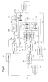
- the method according to the invention is detailed in application to an aircraft 1 comprising at least a first undercarriage with a steerable lower part carrying wheels.
- the aircraft 1 comprises here an auxiliary undercarriage 2 which is located at the front of the fuselage and which comprises a lower part 3 which can be steered by actuators 100.
- a control member 200 controls the actuators 100 of the lower part 3.
- a pilot wishing to make a yaw movement to the aircraft 1 rolling on the ground then acts on different steering members (such as pedals or a control wheel) to generate a set of yaw rate ⁇ c .
- a computer 4 determines an angular prepositioning ⁇ p of the orientation of the wheels of the lower part 3 by a calculation here identical to that explained in the aforementioned thesis.
- mono-variable equalizer 5 determines a yaw torque command M za generating at the aircraft 1 by the auxiliary undercarriage 2 so that the torque M za generated lace allows the aircraft 1 to respond to the yaw rate ⁇ c .
- a second computer 6 translates the yaw torque setpoint M za into an angle setpoint ⁇ z .
- An orientation angle setpoint ⁇ c is then generated to the control member 200, the orientation angle ⁇ c being equal to the sum of the prepositioning ⁇ p and the angle ⁇ z deduced from the set of yaw torque M za .
- the controller 200 controls the actuators 100 so that they guide the lower part 3 of the orientation angle ⁇ c.
- a measurement of the yaw rate ⁇ m of the aircraft 1 is performed. From the measured yaw rate ⁇ m and the yaw rate setpoint ⁇ c , the one-variable corrector 5 determines the yaw torque setpoint M za taking into account an error between the yaw rate setpoint. ⁇ c and the yaw rate measured ⁇ m when the orientable lower part is orientated by the orientation angle ⁇ c .
- the angle setpoint ⁇ z which results from directly to the yaw torque command M za is also determined on the basis of an error between the setpoint yaw rate ⁇ c and the measured yaw speed ⁇ m.
- a yaw rate of the aircraft 1 close to the yaw rate ⁇ c . Then, by a regulation 7 of the orientation angle ⁇ c around the prepositioning, a yaw rate of the aircraft 1 is obtained which conforms to the yaw rate set point ⁇ c , at least under normal operating conditions. orientation of the lower part.
- a measurement of the orientation angle ⁇ m is performed. From the measured orientation angle ⁇ m , the second computer 6 determines the angle setpoint ⁇ z , resulting directly from the yaw torque setpoint M za , taking into account an error between the setpoint of orientation angle ⁇ c and the measured orientation angle ⁇ m . 8 by regulating the orientation angle ⁇ c, one obtains an orientation angle according to the orientation angle ⁇ c setpoint without the first control 7 not directly integrates the error between the setpoint angle of orientation ⁇ c and the measured orientation angle ⁇ m .
- the aircraft 1 further comprises at least two main undercarriages 9, 10 disposed respectively at the rear left and right of the fuselage and whose wheels are associated with torque application members respectively 11, 12.
- said members 11, 12 can create a rotation speed differential between the wheels of the main left undercarriage 9 and the right undercarriage 10.
- the method of the invention integrates the torque application members 11, 12 so simultaneously managing the orientation of the lower part 3 of the undercarriage 1 and a rotation speed differential of the main landing gear 9,10.
- a multi-variable corrector 50 determines simultaneously the yaw torque command M za generating at the aircraft 1 by the auxiliary undercarriage 2 and a complementary yaw torque setpoint M zp to be generated at the level of the aircraft 1 by the torque application members 11, 12 so that the total yaw torque generated by the undercarriage 2 and the application members torque 11,12, allows the aircraft 1 to respond to the yaw rate ⁇ c .
- the torque application members 11, 12 are controlled by a control module 13. From the complementary yaw torque setpoint M zp , the control module 13 generates two acceleration instructions ⁇ g , ⁇ d to the torque application members 11, 12. In certain circumstances (wet track, defective acceleration means, etc.), it may be that one or more of said members can only generate a limited acceleration preventing to achieve the complementary yaw torque setpoint M zp . In this case, a saturation signal Satg, Sat d is sent by the left main landing gear 9 or right 10 to the control module 13 which then takes into account this saturation to generate acceleration instructions ⁇ g , ⁇ d allowing to get as close as possible to the complementary yaw torque setpoint M zp required.
- a saturation signal Satg, Sat d is sent by the left main landing gear 9 or right 10 to the control module 13 which then takes into account this saturation to generate acceleration instructions ⁇ g , ⁇ d allowing to get as close as possible to the complementary yaw torque setpoint M z
- the multi-variable corrector 50 simultaneously determines the yaw torque command M za to be generated by the auxiliary undercarriage 2 and the complementary yaw torque setpoint M zp to be generated by the members application torque 11, 12 so that the total yaw torque allows the aircraft 1 to respond to the yaw rate ⁇ c .
- the multi-variable corrector 50 takes account of an error between the yaw rate instruction ⁇ c and the measured yaw rate ⁇ m when the steerable lower part 3 is oriented from the orientation angle ⁇ c and the torque application members 11, 12 rotated with an acceleration ⁇ g , ⁇ d .
- an acceleration regulation of the torque application members 11, 12 is also obtained.
- a third computer 14 translates the yaw rate setpoint ⁇ c ⁇ in a rotation speed differential setpoint ⁇ c, said target being then transmitted to the multi-variable corrector 50.
- a measurement of the average rotation speeds ⁇ g , ⁇ d of the wheels of the main landing gear respectively left and right 9,10 is performed.
- a fourth computer 15 determines a measured rotation speed differential ⁇ ⁇ m which is then transmitted to the multi-variable corrector 50.
- the multi-variable corrector 50 determines the complementary yaw torque setpoint M zp to be generated by the torque application members 11, 12 taking into account the an error between the rotational speed differential setpoint ⁇ ⁇ c and the measured rotational speed differential ⁇ ⁇ m .
- a third regulation 16 one obtains the accelerations of the wheels of the left and right main undercarriages 9,10 in accordance with the acceleration instructions ⁇ g , ⁇ d without the first regulation 7 directly integrating the error between the rotation speed differential setpoint ⁇ ⁇ c and the rotational speed differential measured ⁇ ⁇ m .
- acceleration of the wheels of the main undercarriages 9,10 is meant as well a positive acceleration of the wheels as a negative acceleration of the wheels, the negative acceleration being also called deceleration.
- the aircraft 1 comprises an auxiliary undercarriage at the front 2 and two main undercarriages at the rear 9, 10, the undercarriages can of course have any other arrangement.
- the aircraft 1 may include a different number of undercarriages and each undercarriage may include a different number of wheels.
Abstract
Description
L'invention concerne un procédé de gestion d'un mouvement de lacet d'un aéronef roulant au sol.The invention relates to a method for managing a yaw movement of an aircraft taxiing on the ground.
On rappelle qu'un aéronef comporte un train d'atterrissage, qui comporte plusieurs atterrisseurs, dans le but d'assurer une interface entre l'aéronef et le sol.It will be recalled that an aircraft comprises a landing gear, which comprises several landing gear, in order to provide an interface between the aircraft and the ground.
Habituellement, un pilote contrôle un mouvement de lacet d'un aéronef roulant au sol en agissant sur des organes de pilotage (pédales d'un palonnier, volant de commande ...). Dans le cas d'un aéronef comportant au moins un atterrisseur avec une partie basse orientable portant des roues, les organes de pilotage sollicitent directement, à partir d'une loi de pilotage dépendant de la vitesse de l'aéronef, la partie basse orientable.Usually, a pilot controls a yaw movement of an aircraft taxiing on the ground by acting on steering members (pedals of a rudder, control wheel, etc.). In the case of an aircraft comprising at least one undercarriage with a steerable lower part carrying wheels, the steering members directly request, from a control law depending on the speed of the aircraft, the steerable lower part.
Il est connu de la thèse « Automatisation du pilotage au sol pour la navigation portuaire » rédigé par M. Jean DUPREZ pour Airbus France - LAAS en 2004 (accessible sur le site Internet des thèses en ligne http://tel.archives-ouvertes.fr/) de modifier la loi de pilotage afin d'aider davantage le pilote à gérer le mouvement de lacet. La thèse décrit ainsi le procédé suivant :
- à partir d'un ordre généré par des organes de pilotage, déterminer un prépositionnement angulaire d'orientation des roues de la partie basse de l'atterrisseur;
- mettre en oeuvre une boucle d'asservissement ayant pour entrée le prépositionnement et générant une correction de celui-ci;
- orienter la partie basse d'un angle d'orientation égal au prépositionnement duquel on a soustrait la correction.
- from an order generated by the steering members, determining an angular orientation prepositioning of the wheels of the lower part of the undercarriage;
- implementing a servo loop having as input the prepositioning and generating a correction thereof;
- orient the lower part of an orientation angle equal to the prepositioning from which the correction has been subtracted.
L'objet de l'invention est de proposer un procédé de gestion d'un mouvement de lacet d'un aéronef roulant au sol dans lequel l'angle d'orientation de la partie basse est asservi de façon différente.The object of the invention is to provide a method of managing a yaw movement of a taxiing aircraft in which the angle of orientation of the lower part is slaved differently.
En vue de la réalisation de ce but, on propose un procédé de gestion d'un mouvement de lacet d'un aéronef roulant au sol, l'aéronef comportant au moins un premier atterrisseur avec une partie basse orientable portant des roues.In order to achieve this goal, there is provided a method for managing a yaw movement of an aircraft taxiing on the ground, the aircraft comprising at least one first undercarriage with a pivotable lower part carrying wheels.
Selon l'invention, le procédé comporte les étapes de :
- à partir d'une consigne de vitesse de lacet, déterminer un prépositionnement angulaire d'orientation des roues ;
- mettre en oeuvre une boucle d'asservissement ayant pour entrée la consigne de vitesse de lacet et générant un ordre d'orientation de la partie basse pour orienter celle-ci d'un angle d'orientation égal à la somme du prépositionnement et d'un angle qui est déterminé en tenant compte d'une erreur entre la consigne de vitesse de lacet et la vitesse de lacet mesurée lorsque la partie basse orientable est orientée de l'angle d'orientation.
- from a yaw rate setpoint, determine an angular prepositioning of the wheels orientation;
- implementing a servo loop having as input the yaw rate instruction and generating an order of orientation of the lower part to orientate it with an orientation angle equal to the sum of the prepositioning and a angle which is determined by taking into account an error between the yaw rate setpoint and the yaw rate measured when the steerable lower part is oriented from the steering angle.
Ainsi, la partie basse est orientée par régulation de l'angle d'orientation autour d'une position de prépositionnement de la partie basse.Thus, the lower part is oriented by regulating the orientation angle around a prepositioning position of the lower part.
Selon un mode de réalisation privilégié de l'invention, le procédé est appliqué à un aéronef comportant en outre au moins deux atterrisseurs principaux disposés respectivement à gauche et à droite du fuselage et dont les roues sont associées à des organes d'application de couple, le procédé comportant l'étape de générer, à destination des organes d'application de couple des atterrisseurs principaux gauche et droit, deux consignes d'accélération de sorte que les organes ainsi sollicités génèrent au niveau de l'aéronef un couple de lacet complémentaire au couple de lacet généré par le premier atterrisseur de sorte que le couple de lacet total généré au niveau de l'aéronef permette à l'aéronef de répondre à la consigne de vitesse de lacet.According to a preferred embodiment of the invention, the method is applied to an aircraft further comprising at least two main landing gear disposed respectively to the left and right of the fuselage and whose wheels are associated with torque application members, the method comprising the step of generating, to the torque application members of the main landing gear left and right, two instructions acceleration so that the organs thus solicited generate at the aircraft a pair of yaw complementary to the yaw torque generated by the first undercarriage so that the total yaw torque generated at the level of the aircraft allows the aircraft to respond to the yaw rate instruction.
Les organes d'application de couple sont par exemple des freins à friction et/ou des dispositifs de déplacement autonome, un dispositif de déplacement autonome comportant un moteur.The torque application members are for example friction brakes and / or autonomous displacement devices, an autonomous displacement device comprising a motor.
Le procédé selon l'invention permet ainsi de gérer de façon simultanée, par répartition du couple de lacet, à la fois l'orientation de la partie basse du premier atterrisseur et un différentiel de vitesses de rotation des atterrisseurs principaux. Le pilote n'a plus à se soucier de la façon dont les commandes sont réparties pour agir sur l'orientation de la partie basse et sur l'accélération des roues des atterrisseurs principaux.The method according to the invention thus makes it possible to simultaneously manage, by distribution of the yaw torque, both the orientation of the lower part of the first undercarriage and a rotation speed differential of the main undercarriages. The pilot no longer has to worry about how the controls are distributed to act on the orientation of the lower part and the acceleration of the wheels of the main landing gear.
L'invention sera mieux comprise à la lumière de la description qui suit d'un mode de réalisation particulier non limitatif de l'invention en référence aux figures des dessins annexés parmi lesquels:
- la
figure 1 est un schéma de principe de mise en oeuvre du procédé selon l'invention ; - la
figure 2 est un schéma de principe de mise en oeuvre du procédé selon l'invention dans un mode de réalisation privilégié.
- the
figure 1 is a block diagram of implementation of the method according to the invention; - the
figure 2 is a block diagram of implementation of the method according to the invention in a preferred embodiment.
En référence à la
Un pilote souhaitant faire réaliser un mouvement de lacet à l'aéronef 1 roulant au sol agit alors sur différents organes de pilotage (comme des pédales de palonnier ou un volant de commande) pour générer une consigne de vitesse de lacet ϕ̇ c .A pilot wishing to make a yaw movement to the aircraft 1 rolling on the ground then acts on different steering members (such as pedals or a control wheel) to generate a set of yaw rate φ̇ c .
A partir de la consigne de vitesse de lacet ϕ̇ c , un calculateur 4 détermine un prépositionnement angulaire θp d'orientation des roues de la partie basse 3 par un calcul ici identique à celui explicité dans la thèse précitée.From the yaw rate instruction φ̇ c , a
Parallèlement, à partir de la consigne de vitesse de lacet ϕ̇ c , un correcteur mono-variable 5 détermine une consigne de couple de lacet Mza à générer au niveau de l'aéronef 1 par l'atterrisseur auxiliaire 2 de sorte que le couple de lacet Mza généré permette à l'aéronef 1 de répondre à la consigne de vitesse de lacet ϕ̇c. Puis, un deuxième calculateur 6 traduit la consigne de couple de lacet Mza en une consigne d'angle θz. Une consigne d'angle d'orientation θc est ensuite générée à destination de l'organe de commande 200, l'angle d'orientation θc étant égal à la somme du prépositionnement θp et de l'angle θz déduit de la consigne de couple de lacet Mza. A partir de la consigne d'orientation θc, l'organe de commande 200 commande les actionneurs 100 pour que ceux-ci orientent la partie basse 3 de l'angle d'orientation θc.Meanwhile, from the yaw speed reference φ̇ c, mono-variable equalizer 5 determines a yaw torque command M za generating at the aircraft 1 by the
Selon l'invention, à tout instant du mouvement de lacet, une mesure de la vitesse de lacet ϕ̇ m de l'aéronef 1 est effectuée. A partir de la vitesse de lacet mesurée ϕ̇ m et de la consigne de vitesse de lacet ϕ̇ c , le correcteur mono-variable 5 détermine la consigne de couple de lacet Mza en tenant compte d'une erreur entre la consigne de vitesse de lacet ϕ̇c et la vitesse de lacet mesurée ϕ̇ m lorsque la partie basse orientable est orientée de l'angle d'orientation θc. Ainsi la consigne d'angle θz, découlant directement de la consigne de couple de lacet Mza, est également déterminée en tenant compte d'une erreur entre la consigne de vitesse de lacet ϕ̇ c et la vitesse de lacet mesurée ϕ̇ m .According to the invention, at any instant of the yaw movement, a measurement of the yaw rate φ̇ m of the aircraft 1 is performed. From the measured yaw rate φ̇ m and the yaw rate setpoint φ̇ c , the one-variable corrector 5 determines the yaw torque setpoint M za taking into account an error between the yaw rate setpoint. φ̇ c and the yaw rate measured φ̇ m when the orientable lower part is orientated by the orientation angle θ c . Thus the angle setpoint θ z , which results from directly to the yaw torque command M za is also determined on the basis of an error between the setpoint yaw rate φ̇ c and the measured yaw speed φ̇ m.
Grâce au prépositionnement, on obtient rapidement une vitesse de lacet de l'aéronef 1 proche de la consigne de vitesse de lacet ϕ̇ c . Puis, par une régulation 7 de l'angle d'orientation θc autour du prépositionnement, on obtient une vitesse de lacet de l'aéronef 1 conforme à la consigne de vitesse de lacet ϕ̇ c , au moins dans des conditions normales de fonctionnement d'orientation de la partie basse.Thanks to the prepositioning, one quickly obtains a yaw rate of the aircraft 1 close to the yaw rate φ̇ c . Then, by a
Ici, à tout instant du mouvement de lacet, une mesure de l'angle d'orientation θm est effectuée. A partir de l'angle d'orientation mesuré θm, le deuxième calculateur 6 détermine la consigne d'angle θz, découlant directement de la consigne de couple de lacet Mza, en tenant compte d'une erreur entre la consigne d'angle d'orientation θc et l'angle d'orientation mesuré θm. Par une régulation 8 de l'angle d'orientation θc, on obtient un angle d'orientation conforme à la consigne d'angle d'orientation θc sans que la première régulation 7 n'intègre directement l'erreur entre la consigne d'angle d'orientation θc et l'angle d'orientation mesuré θm.Here, at any instant of the yaw movement, a measurement of the orientation angle θ m is performed. From the measured orientation angle θ m , the
En référence à la
A cet effet, à partir de la consigne de vitesse de lacet ϕ̇ c , un correcteur multi-variables 50 détermine alors simultanément la consigne de couple de lacet Mza à générer au niveau de l'aéronef 1 par l'atterrisseur auxiliaire 2 et une consigne de couple de lacet complémentaire Mzp à générer au niveau de l'aéronef 1 par les organes d'application de couple 11,12 de sorte que le couple de lacet total, généré par l'atterrisseur auxiliaire 2 et les organes d'application de couple 11,12, permette à l'aéronef 1 de répondre à la consigne de vitesse de lacet ϕ̇ c .For this purpose, from the yaw speed reference φ̇ c, a
De façon connue en soi, les organes d'application de couple 11, 12 sont commandés par un module de commande 13. A partir de la consigne de couple de lacet complémentaire Mzp, le module de commande 13 génère deux consignes d'accélération Γg, Γd à destination des organes d'application de couple 11, 12. Dans certaines circonstances (piste humide, moyens d'accélération défectueux...), il se peut que l'un ou plusieurs desdits organes ne puissent générer qu'une accélération limitée empêchant de réaliser la consigne de couple de lacet complémentaire Mzp. Dans ce cas, un signal de saturation Satg, Satd est envoyé par l'atterrisseur principal gauche 9 ou droit 10 concerné au module de commande 13 qui tient alors compte de cette saturation pour générer des consignes d'accélération Γg, Γd permettant de s'approcher au mieux de la consigne de couple de lacet complémentaire Mzp requise.In a manner known per se, the
Selon l'invention à partir de la mesure de la vitesse de lacet ϕ̇ m et de la consigne de vitesse de lacet ϕ̇ c , le correcteur multi-variables 50 détermine simultanément la consigne de couple de lacet Mza à générer par l'atterrisseur auxiliaire 2 et la consigne de couple de lacet complémentaire Mzp à générer par les organes d'application de couple 11, 12 de sorte que le couple de lacet total permette à l'aéronef 1 de répondre à la consigne de vitesse de lacet ϕ̇ c . Pour cela, le correcteur multi-variables 50 tient compte d'une erreur entre la consigne de vitesse de lacet ϕ̇ c et la vitesse de lacet mesurée ϕ̇ m lorsque la partie basse orientable 3 est orientée de l'angle d'orientation θ c et les organes d'application de couple 11, 12 entrainés en rotation avec une accélération Γg, Γd. Par la première régulation 7, on obtient également une régulation en accélération des organes d'application de couple 11, 12.According to the invention from the measurement of φ̇ m yaw rate and the yaw rate setpoint φ̇ c, the
Ici, un troisième calculateur 14 traduit la consigne de vitesse de lacet ϕ̇ c en une consigne de différentiel de vitesse de rotation Δωc , ladite consigne étant ensuite transmise au correcteur multi-variables 50. En outre, à tout instant du mouvement de lacet, une mesure des vitesses de rotation moyenne ω̅g,ω̅d des roues des atterrisseurs principaux respectivement gauche et droit 9,10 est effectuée. A partir des vitesses de rotation moyenne mesurées ω̅g,ω̅d un quatrième calculateur 15 détermine un différentiel de vitesse de rotation mesuré Δωm qui est ensuite transmis au correcteur multi-variables 50. A partir de la consigne de différentiel de vitesse de rotation Δωc et du différentiel de vitesse de rotation mesuré Δωm , le correcteur multi-variables 50 détermine alors la consigne de couple de lacet complémentaire Mzp à générer par les organes d'application de couple 11, 12 en tenant compte d'une erreur entre la consigne de différentiel de vitesse de rotation Δωc et le différentiel de vitesse de rotation mesuré Δωm . Par une troisième régulation 16, on obtient les accélérations des roues des atterrisseurs principaux gauche et droit 9,10 conformes aux consignes d'accélération Γg, Γd sans que la première régulation 7 n'intègre directement l'erreur entre la consigne de différentiel de vitesse de rotation Δωc et le différentiel de vitesse de rotation mesuré Δωm .Here, a
Bien entendu l'invention n'est pas limitée au mode de mise en oeuvre décrit et on peut y apporter des variantes de réalisation sans sortir du cadre de l'invention tel que défini par les revendications.Naturally, the invention is not limited to the embodiment described and variations can be made without departing from the scope of the invention as defined by the claims.
En particulier, en utilisant ici le terme d'accélération des roues des atterrisseurs principaux 9,10, on entend tout aussi bien une accélération positive des roues qu'une accélération négative des roues, l'accélération négative étant également nommée décélération.In particular, using here the term of acceleration of the wheels of the
Bien que l'on ait indiqué que l'aéronef 1 comportait un atterrisseur auxiliaire à l'avant 2 et deux atterrisseurs principaux à l'arrière 9, 10, les atterrisseurs pourront bien entendu avoir une toute autre disposition. En outre, l'aéronef 1 pourra comporter un tout autre nombre d'atterrisseurs et chaque atterrisseur pourra comporter un tout autre nombre de roues.Although it has been said that the aircraft 1 comprises an auxiliary undercarriage at the
Claims (6)
ϕ̇ c et la vitesse de lacet mesurée ϕ̇ m .Method according to Claim 3, in which the acceleration setpoints Γ g , Γ d are generated taking into account an error between the yaw rate setpoint
φ̇ c and the measured yaw rate φ̇ m .
Applications Claiming Priority (1)
| Application Number | Priority Date | Filing Date | Title |
|---|---|---|---|
| FR1056655A FR2963968B1 (en) | 2010-08-18 | 2010-08-18 | METHOD FOR MANAGING A LACET MOVEMENT OF A GROUNDING AIRCRAFT. |
Publications (2)
| Publication Number | Publication Date |
|---|---|
| EP2420909A1 true EP2420909A1 (en) | 2012-02-22 |
| EP2420909B1 EP2420909B1 (en) | 2014-12-10 |
Family
ID=43506288
Family Applications (1)
| Application Number | Title | Priority Date | Filing Date |
|---|---|---|---|
| EP20110177235 Active EP2420909B1 (en) | 2010-08-18 | 2011-08-11 | Method for managing a yaw movement of a taxiing aircraft. |
Country Status (6)
| Country | Link |
|---|---|
| US (1) | US8666598B2 (en) |
| EP (1) | EP2420909B1 (en) |
| CN (1) | CN102411370B (en) |
| BR (1) | BRPI1103811A2 (en) |
| CA (1) | CA2750071C (en) |
| FR (1) | FR2963968B1 (en) |
Families Citing this family (10)
| Publication number | Priority date | Publication date | Assignee | Title |
|---|---|---|---|---|
| GB201220618D0 (en) * | 2012-11-16 | 2013-01-02 | Airbus Operations Ltd | Landing gear force and moment distributer |
| WO2014168674A2 (en) * | 2013-01-31 | 2014-10-16 | Flir Systems, Inc. | Stabilized directional control systems and methods |
| US9472110B2 (en) * | 2013-12-03 | 2016-10-18 | Honeywell International Inc. | Aircraft taxi path guidance and display |
| US20150375854A1 (en) * | 2014-06-27 | 2015-12-31 | Honeywell International Inc. | Differential steering control of electric taxi landing gear |
| GB2534915A (en) * | 2015-02-05 | 2016-08-10 | Airbus Operations Ltd | Method and apparatus for control of a steerable landing gear |
| GB2540182A (en) | 2015-07-08 | 2017-01-11 | Airbus Operations Ltd | Aircraft steering system controller |
| CN105083587B (en) * | 2015-08-14 | 2017-04-19 | 中国航空工业集团公司西安飞机设计研究所 | Load correction method applied to undercarriage loading |
| FR3044811B1 (en) * | 2015-12-08 | 2018-01-12 | Airbus Operations | METHOD AND DEVICE FOR ESTIMATING A SIDE SPEED AND A LATERAL POSITION OF AN AIRCRAFT DURING AN AIRCRAFT RUNNING PHASE. |
| EP3232284B1 (en) | 2016-04-11 | 2019-09-11 | Airbus Operations Limited | Method and apparatus for control of a steerable landing gear |
| CN106586026B (en) * | 2016-12-06 | 2019-01-08 | 中国航空工业集团公司洛阳电光设备研究所 | A kind of measurement method of aircraft with respect to runway lateral deviation rate |
Citations (2)
| Publication number | Priority date | Publication date | Assignee | Title |
|---|---|---|---|---|
| US20060186267A1 (en) * | 2005-02-23 | 2006-08-24 | The Boeing Company | Systems and methods for braking aircraft, including braking intermediate main gears and differential braking |
| US20090150010A1 (en) * | 2007-12-11 | 2009-06-11 | Airbus France | Method and device for generating a yaw speed order for an aircraft during a taxiing |
Family Cites Families (9)
| Publication number | Priority date | Publication date | Assignee | Title |
|---|---|---|---|---|
| US3774340A (en) * | 1972-06-19 | 1973-11-27 | Marvin Glass & Associates | System for operating miniature vehicles |
| US4482961A (en) * | 1981-09-18 | 1984-11-13 | The Boeing Company | Automatic control system for directional control of an aircraft during landing rollout |
| US4621833A (en) * | 1985-12-16 | 1986-11-11 | Ford Motor Company | Control system for multistable suspension unit |
| DE19638316C1 (en) * | 1996-09-19 | 1998-02-19 | Lemfoerder Metallwaren Ag | Motor vehicle steering column assembly |
| US5906120A (en) * | 1998-04-09 | 1999-05-25 | Ford Global Technologies, Inc. | Automotive vehicle steering column lock mechanism |
| US6814413B2 (en) * | 2001-05-31 | 2004-11-09 | Delphi Technologies, Inc. | Hydraulic brake and steering assist system |
| US7143864B2 (en) * | 2002-09-27 | 2006-12-05 | Ford Global Technologies, Llc. | Yaw control for an automotive vehicle using steering actuators |
| US7798263B2 (en) * | 2006-05-03 | 2010-09-21 | Tandy Engineering & Associates, Inc. | Stability enhancing system for tow-vehicle and trailer assembly combination with two processors |
| US7731302B2 (en) * | 2006-05-03 | 2010-06-08 | Tandy Engineering & Associates, Inc. | Stability enhancing system for tow-vehicle towing trailer assembly |
-
2010
- 2010-08-18 FR FR1056655A patent/FR2963968B1/en active Active
-
2011
- 2011-08-11 EP EP20110177235 patent/EP2420909B1/en active Active
- 2011-08-16 CN CN201110305918.3A patent/CN102411370B/en active Active
- 2011-08-17 US US13/211,659 patent/US8666598B2/en active Active
- 2011-08-17 CA CA 2750071 patent/CA2750071C/en not_active Expired - Fee Related
- 2011-08-18 BR BRPI1103811-0A patent/BRPI1103811A2/en not_active IP Right Cessation
Patent Citations (2)
| Publication number | Priority date | Publication date | Assignee | Title |
|---|---|---|---|---|
| US20060186267A1 (en) * | 2005-02-23 | 2006-08-24 | The Boeing Company | Systems and methods for braking aircraft, including braking intermediate main gears and differential braking |
| US20090150010A1 (en) * | 2007-12-11 | 2009-06-11 | Airbus France | Method and device for generating a yaw speed order for an aircraft during a taxiing |
Non-Patent Citations (3)
| Title |
|---|
| DUPREZ J ET AL: "Control of the aircraft-on-ground lateral motion during low speed roll and manoeuvers", AEROSPACE CONFERENCE, 2004. PROCEEDINGS. 2004 IEEE,, vol. 4, 6 March 2004 (2004-03-06), IEEE, PISCATAWAY, NJ, USA, pages 2656 - 2666, XP010748389, ISBN: 978-0-7803-8155-1, DOI: 10.1109/AERO.2004.1368061 * |
| J DUPREZ: "Chapitre 4 : Etude d'une loi de pilotage latéral de l'avion au sol", 6 March 2007 (2007-03-06), Université toulouse III-Paul Sabatier, pages 1 - 51, XP002620297, Retrieved from the Internet <URL:http://tel.archives-ouvertes.fr/docs/00/13/50/33/PDF/Memoire.pdf> [retrieved on 20110404] * |
| M. JEAN DUPREZ: "Automatisation du pilotage au sol pour la navigation portuaire", 2004, AIRBUS FRANCE - LAAS |
Also Published As
| Publication number | Publication date |
|---|---|
| EP2420909B1 (en) | 2014-12-10 |
| FR2963968A1 (en) | 2012-02-24 |
| US8666598B2 (en) | 2014-03-04 |
| CN102411370B (en) | 2014-09-10 |
| CA2750071A1 (en) | 2012-02-18 |
| US20120046834A1 (en) | 2012-02-23 |
| FR2963968B1 (en) | 2013-07-05 |
| CA2750071C (en) | 2014-08-05 |
| BRPI1103811A2 (en) | 2015-08-04 |
| CN102411370A (en) | 2012-04-11 |
Similar Documents
| Publication | Publication Date | Title |
|---|---|---|
| EP2420909B1 (en) | Method for managing a yaw movement of a taxiing aircraft. | |
| EP3938260B1 (en) | Method for generating a setpoint for the combined control of a wheel-steering system and of a differential braking system of a motor vehicle | |
| EP1407335B1 (en) | Method and device for controlling satellite attitude and steering using a gyrodyne cluster | |
| EP3282334A1 (en) | Fixed-wing drone, in particular of the flying-wing type, with assisted manual piloting and automatic piloting | |
| CA2803852C (en) | Direction control management process for an adjustable part of aircraft landing gear | |
| CA2717121C (en) | Method and device for the lateral control of a taxiing aircraft | |
| EP1477872B1 (en) | Method and apparatus for guiding an aircraft | |
| FR2883828A1 (en) | DIRECTION OF VEHICLE STEERING WITHOUT MECHANICAL CONNECTION BETWEEN STEERING WHEEL AND WHEELS | |
| FR3072650A1 (en) | SYSTEM FOR CONTROLLING A SIDE TRACK OF AN AIRCRAFT ON THE GROUND | |
| EP2957975B1 (en) | Method and device for controlling at least one actuator control system of an aircraft, related computer program product and aircraft | |
| FR3018364A1 (en) | METHOD OF DETERMINING AN OBSTACLE AVIATION GUIDANCE LAW BY AN AIRCRAFT, COMPUTER PROGRAM PRODUCT, ELECTRONIC SYSTEM AND AIRCRAFT | |
| EP2439604B1 (en) | Method for managing a ground movement of an aircraft. | |
| FR3076530A1 (en) | STEER BY WIRE-TYPE STEERED STEERING SYSTEM USING TRANSPARENT ACTUATED ACTUATORS USING LOCAL TORQUE AND / OR EFFORT LOCAL LOADS | |
| FR3072793B1 (en) | AIRCRAFT TRAJECTORY DISPLAY ASSEMBLY | |
| FR2992072A1 (en) | AUTOMATICALLY CONTROLLED LACET AXIS METHOD FOR MECHANICAL FLIGHT CONTROL AIRCRAFT | |
| CA2935753C (en) | Automatic pilot system for aircraft and associated process | |
| WO2021073925A1 (en) | High-level lateral assistance controller suitable for 4ws vehicles | |
| CA3021893A1 (en) | Aircraft lateral trajectory control system including a rudder input | |
| FR3030448A1 (en) | METHOD FOR MANAGING DISCONTINUITIES IN A VEHICLE CONTROL AFTER A CONTROL TRANSITION, AND VEHICLE | |
| EP2668100B1 (en) | Method and system for piloting a flying craft with rear propulsion unit | |
| EP3663195A1 (en) | Method for controlling the speed of a motor drive of the wheels of an aircraft | |
| EP2027004B1 (en) | Process and control system for vehicle steering wheel | |
| WO2022112047A1 (en) | Method for automated steering of a motor vehicle |
Legal Events
| Date | Code | Title | Description |
|---|---|---|---|
| AK | Designated contracting states |
Kind code of ref document: A1 Designated state(s): AL AT BE BG CH CY CZ DE DK EE ES FI FR GB GR HR HU IE IS IT LI LT LU LV MC MK MT NL NO PL PT RO RS SE SI SK SM TR |
|
| AX | Request for extension of the european patent |
Extension state: BA ME |
|
| PUAI | Public reference made under article 153(3) epc to a published international application that has entered the european phase |
Free format text: ORIGINAL CODE: 0009012 |
|
| 17P | Request for examination filed |
Effective date: 20120821 |
|
| 17Q | First examination report despatched |
Effective date: 20121015 |
|
| GRAP | Despatch of communication of intention to grant a patent |
Free format text: ORIGINAL CODE: EPIDOSNIGR1 |
|
| INTG | Intention to grant announced |
Effective date: 20140203 |
|
| GRAP | Despatch of communication of intention to grant a patent |
Free format text: ORIGINAL CODE: EPIDOSNIGR1 |
|
| INTG | Intention to grant announced |
Effective date: 20140723 |
|
| GRAS | Grant fee paid |
Free format text: ORIGINAL CODE: EPIDOSNIGR3 |
|
| GRAA | (expected) grant |
Free format text: ORIGINAL CODE: 0009210 |
|
| AK | Designated contracting states |
Kind code of ref document: B1 Designated state(s): AL AT BE BG CH CY CZ DE DK EE ES FI FR GB GR HR HU IE IS IT LI LT LU LV MC MK MT NL NO PL PT RO RS SE SI SK SM TR |
|
| REG | Reference to a national code |
Ref country code: GB Ref legal event code: FG4D Free format text: NOT ENGLISH |
|
| REG | Reference to a national code |
Ref country code: CH Ref legal event code: EP |
|
| REG | Reference to a national code |
Ref country code: IE Ref legal event code: FG4D Free format text: LANGUAGE OF EP DOCUMENT: FRENCH |
|
| REG | Reference to a national code |
Ref country code: AT Ref legal event code: REF Ref document number: 700946 Country of ref document: AT Kind code of ref document: T Effective date: 20150115 |
|
| REG | Reference to a national code |
Ref country code: DE Ref legal event code: R096 Ref document number: 602011012072 Country of ref document: DE Effective date: 20150122 |
|
| REG | Reference to a national code |
Ref country code: AT Ref legal event code: MK05 Ref document number: 700946 Country of ref document: AT Kind code of ref document: T Effective date: 20141210 Ref country code: NL Ref legal event code: VDEP Effective date: 20141210 |
|
| REG | Reference to a national code |
Ref country code: NL Ref legal event code: VDEP Effective date: 20141210 |
|
| PG25 | Lapsed in a contracting state [announced via postgrant information from national office to epo] |
Ref country code: LT Free format text: LAPSE BECAUSE OF FAILURE TO SUBMIT A TRANSLATION OF THE DESCRIPTION OR TO PAY THE FEE WITHIN THE PRESCRIBED TIME-LIMIT Effective date: 20141210 Ref country code: NO Free format text: LAPSE BECAUSE OF FAILURE TO SUBMIT A TRANSLATION OF THE DESCRIPTION OR TO PAY THE FEE WITHIN THE PRESCRIBED TIME-LIMIT Effective date: 20150310 Ref country code: ES Free format text: LAPSE BECAUSE OF FAILURE TO SUBMIT A TRANSLATION OF THE DESCRIPTION OR TO PAY THE FEE WITHIN THE PRESCRIBED TIME-LIMIT Effective date: 20141210 Ref country code: FI Free format text: LAPSE BECAUSE OF FAILURE TO SUBMIT A TRANSLATION OF THE DESCRIPTION OR TO PAY THE FEE WITHIN THE PRESCRIBED TIME-LIMIT Effective date: 20141210 |
|
| REG | Reference to a national code |
Ref country code: DE Ref legal event code: R082 Ref document number: 602011012072 Country of ref document: DE Representative=s name: SCHAUMBURG & PARTNER PATENTANWAELTE GBR, DE Ref country code: DE Ref legal event code: R082 Ref document number: 602011012072 Country of ref document: DE Representative=s name: SCHAUMBURG & PARTNER PATENTANWAELTE MBB, DE Ref country code: DE Ref legal event code: R082 Ref document number: 602011012072 Country of ref document: DE Representative=s name: SCHAUMBURG UND PARTNER PATENTANWAELTE MBB, DE |
|
| REG | Reference to a national code |
Ref country code: LT Ref legal event code: MG4D |
|
| PG25 | Lapsed in a contracting state [announced via postgrant information from national office to epo] |
Ref country code: RS Free format text: LAPSE BECAUSE OF FAILURE TO SUBMIT A TRANSLATION OF THE DESCRIPTION OR TO PAY THE FEE WITHIN THE PRESCRIBED TIME-LIMIT Effective date: 20141210 Ref country code: SE Free format text: LAPSE BECAUSE OF FAILURE TO SUBMIT A TRANSLATION OF THE DESCRIPTION OR TO PAY THE FEE WITHIN THE PRESCRIBED TIME-LIMIT Effective date: 20141210 Ref country code: AT Free format text: LAPSE BECAUSE OF FAILURE TO SUBMIT A TRANSLATION OF THE DESCRIPTION OR TO PAY THE FEE WITHIN THE PRESCRIBED TIME-LIMIT Effective date: 20141210 Ref country code: GR Free format text: LAPSE BECAUSE OF FAILURE TO SUBMIT A TRANSLATION OF THE DESCRIPTION OR TO PAY THE FEE WITHIN THE PRESCRIBED TIME-LIMIT Effective date: 20150311 Ref country code: HR Free format text: LAPSE BECAUSE OF FAILURE TO SUBMIT A TRANSLATION OF THE DESCRIPTION OR TO PAY THE FEE WITHIN THE PRESCRIBED TIME-LIMIT Effective date: 20141210 Ref country code: LV Free format text: LAPSE BECAUSE OF FAILURE TO SUBMIT A TRANSLATION OF THE DESCRIPTION OR TO PAY THE FEE WITHIN THE PRESCRIBED TIME-LIMIT Effective date: 20141210 |
|
| REG | Reference to a national code |
Ref country code: FR Ref legal event code: PLFP Year of fee payment: 5 |
|
| PG25 | Lapsed in a contracting state [announced via postgrant information from national office to epo] |
Ref country code: NL Free format text: LAPSE BECAUSE OF FAILURE TO SUBMIT A TRANSLATION OF THE DESCRIPTION OR TO PAY THE FEE WITHIN THE PRESCRIBED TIME-LIMIT Effective date: 20141210 |
|
| PG25 | Lapsed in a contracting state [announced via postgrant information from national office to epo] |
Ref country code: CZ Free format text: LAPSE BECAUSE OF FAILURE TO SUBMIT A TRANSLATION OF THE DESCRIPTION OR TO PAY THE FEE WITHIN THE PRESCRIBED TIME-LIMIT Effective date: 20141210 Ref country code: SK Free format text: LAPSE BECAUSE OF FAILURE TO SUBMIT A TRANSLATION OF THE DESCRIPTION OR TO PAY THE FEE WITHIN THE PRESCRIBED TIME-LIMIT Effective date: 20141210 Ref country code: EE Free format text: LAPSE BECAUSE OF FAILURE TO SUBMIT A TRANSLATION OF THE DESCRIPTION OR TO PAY THE FEE WITHIN THE PRESCRIBED TIME-LIMIT Effective date: 20141210 Ref country code: PT Free format text: LAPSE BECAUSE OF FAILURE TO SUBMIT A TRANSLATION OF THE DESCRIPTION OR TO PAY THE FEE WITHIN THE PRESCRIBED TIME-LIMIT Effective date: 20150410 Ref country code: RO Free format text: LAPSE BECAUSE OF FAILURE TO SUBMIT A TRANSLATION OF THE DESCRIPTION OR TO PAY THE FEE WITHIN THE PRESCRIBED TIME-LIMIT Effective date: 20141210 |
|
| PG25 | Lapsed in a contracting state [announced via postgrant information from national office to epo] |
Ref country code: IS Free format text: LAPSE BECAUSE OF FAILURE TO SUBMIT A TRANSLATION OF THE DESCRIPTION OR TO PAY THE FEE WITHIN THE PRESCRIBED TIME-LIMIT Effective date: 20150410 Ref country code: PL Free format text: LAPSE BECAUSE OF FAILURE TO SUBMIT A TRANSLATION OF THE DESCRIPTION OR TO PAY THE FEE WITHIN THE PRESCRIBED TIME-LIMIT Effective date: 20141210 |
|
| REG | Reference to a national code |
Ref country code: DE Ref legal event code: R097 Ref document number: 602011012072 Country of ref document: DE |
|
| PLBE | No opposition filed within time limit |
Free format text: ORIGINAL CODE: 0009261 |
|
| STAA | Information on the status of an ep patent application or granted ep patent |
Free format text: STATUS: NO OPPOSITION FILED WITHIN TIME LIMIT |
|
| PG25 | Lapsed in a contracting state [announced via postgrant information from national office to epo] |
Ref country code: DK Free format text: LAPSE BECAUSE OF FAILURE TO SUBMIT A TRANSLATION OF THE DESCRIPTION OR TO PAY THE FEE WITHIN THE PRESCRIBED TIME-LIMIT Effective date: 20141210 |
|
| 26N | No opposition filed |
Effective date: 20150911 |
|
| PG25 | Lapsed in a contracting state [announced via postgrant information from national office to epo] |
Ref country code: IT Free format text: LAPSE BECAUSE OF FAILURE TO SUBMIT A TRANSLATION OF THE DESCRIPTION OR TO PAY THE FEE WITHIN THE PRESCRIBED TIME-LIMIT Effective date: 20141210 |
|
| PG25 | Lapsed in a contracting state [announced via postgrant information from national office to epo] |
Ref country code: SI Free format text: LAPSE BECAUSE OF FAILURE TO SUBMIT A TRANSLATION OF THE DESCRIPTION OR TO PAY THE FEE WITHIN THE PRESCRIBED TIME-LIMIT Effective date: 20141210 |
|
| PG25 | Lapsed in a contracting state [announced via postgrant information from national office to epo] |
Ref country code: MC Free format text: LAPSE BECAUSE OF FAILURE TO SUBMIT A TRANSLATION OF THE DESCRIPTION OR TO PAY THE FEE WITHIN THE PRESCRIBED TIME-LIMIT Effective date: 20141210 Ref country code: LU Free format text: LAPSE BECAUSE OF FAILURE TO SUBMIT A TRANSLATION OF THE DESCRIPTION OR TO PAY THE FEE WITHIN THE PRESCRIBED TIME-LIMIT Effective date: 20150811 |
|
| REG | Reference to a national code |
Ref country code: CH Ref legal event code: PL |
|
| PG25 | Lapsed in a contracting state [announced via postgrant information from national office to epo] |
Ref country code: CH Free format text: LAPSE BECAUSE OF NON-PAYMENT OF DUE FEES Effective date: 20150831 Ref country code: LI Free format text: LAPSE BECAUSE OF NON-PAYMENT OF DUE FEES Effective date: 20150831 |
|
| REG | Reference to a national code |
Ref country code: IE Ref legal event code: MM4A |
|
| PG25 | Lapsed in a contracting state [announced via postgrant information from national office to epo] |
Ref country code: IE Free format text: LAPSE BECAUSE OF NON-PAYMENT OF DUE FEES Effective date: 20150811 |
|
| REG | Reference to a national code |
Ref country code: FR Ref legal event code: PLFP Year of fee payment: 6 |
|
| PG25 | Lapsed in a contracting state [announced via postgrant information from national office to epo] |
Ref country code: MT Free format text: LAPSE BECAUSE OF FAILURE TO SUBMIT A TRANSLATION OF THE DESCRIPTION OR TO PAY THE FEE WITHIN THE PRESCRIBED TIME-LIMIT Effective date: 20141210 |
|
| PG25 | Lapsed in a contracting state [announced via postgrant information from national office to epo] |
Ref country code: SM Free format text: LAPSE BECAUSE OF FAILURE TO SUBMIT A TRANSLATION OF THE DESCRIPTION OR TO PAY THE FEE WITHIN THE PRESCRIBED TIME-LIMIT Effective date: 20141210 Ref country code: HU Free format text: LAPSE BECAUSE OF FAILURE TO SUBMIT A TRANSLATION OF THE DESCRIPTION OR TO PAY THE FEE WITHIN THE PRESCRIBED TIME-LIMIT; INVALID AB INITIO Effective date: 20110811 Ref country code: BG Free format text: LAPSE BECAUSE OF FAILURE TO SUBMIT A TRANSLATION OF THE DESCRIPTION OR TO PAY THE FEE WITHIN THE PRESCRIBED TIME-LIMIT Effective date: 20141210 |
|
| REG | Reference to a national code |
Ref country code: FR Ref legal event code: CD Owner name: MESSIER-BUGATTI-DOWTY, FR Effective date: 20170518 |
|
| PG25 | Lapsed in a contracting state [announced via postgrant information from national office to epo] |
Ref country code: CY Free format text: LAPSE BECAUSE OF FAILURE TO SUBMIT A TRANSLATION OF THE DESCRIPTION OR TO PAY THE FEE WITHIN THE PRESCRIBED TIME-LIMIT Effective date: 20141210 |
|
| PG25 | Lapsed in a contracting state [announced via postgrant information from national office to epo] |
Ref country code: BE Free format text: LAPSE BECAUSE OF NON-PAYMENT OF DUE FEES Effective date: 20150831 |
|
| REG | Reference to a national code |
Ref country code: FR Ref legal event code: PLFP Year of fee payment: 7 |
|
| PG25 | Lapsed in a contracting state [announced via postgrant information from national office to epo] |
Ref country code: TR Free format text: LAPSE BECAUSE OF FAILURE TO SUBMIT A TRANSLATION OF THE DESCRIPTION OR TO PAY THE FEE WITHIN THE PRESCRIBED TIME-LIMIT Effective date: 20141210 |
|
| PG25 | Lapsed in a contracting state [announced via postgrant information from national office to epo] |
Ref country code: MK Free format text: LAPSE BECAUSE OF FAILURE TO SUBMIT A TRANSLATION OF THE DESCRIPTION OR TO PAY THE FEE WITHIN THE PRESCRIBED TIME-LIMIT Effective date: 20141210 |
|
| REG | Reference to a national code |
Ref country code: FR Ref legal event code: PLFP Year of fee payment: 8 |
|
| PG25 | Lapsed in a contracting state [announced via postgrant information from national office to epo] |
Ref country code: AL Free format text: LAPSE BECAUSE OF FAILURE TO SUBMIT A TRANSLATION OF THE DESCRIPTION OR TO PAY THE FEE WITHIN THE PRESCRIBED TIME-LIMIT Effective date: 20141210 |
|
| PGFP | Annual fee paid to national office [announced via postgrant information from national office to epo] |
Ref country code: GB Payment date: 20230720 Year of fee payment: 13 |
|
| PGFP | Annual fee paid to national office [announced via postgrant information from national office to epo] |
Ref country code: FR Payment date: 20230720 Year of fee payment: 13 Ref country code: DE Payment date: 20230720 Year of fee payment: 13 |