EP2731853B1 - Lawn care vehicle with rear wheel steering assembly - Google Patents
Lawn care vehicle with rear wheel steering assembly Download PDFInfo
- Publication number
- EP2731853B1 EP2731853B1 EP11869248.2A EP11869248A EP2731853B1 EP 2731853 B1 EP2731853 B1 EP 2731853B1 EP 11869248 A EP11869248 A EP 11869248A EP 2731853 B1 EP2731853 B1 EP 2731853B1
- Authority
- EP
- European Patent Office
- Prior art keywords
- pulley
- steering
- cable portion
- cable
- lawn care
- Prior art date
- Legal status (The legal status is an assumption and is not a legal conclusion. Google has not performed a legal analysis and makes no representation as to the accuracy of the status listed.)
- Not-in-force
Links
Images


Classifications
-
- B—PERFORMING OPERATIONS; TRANSPORTING
- B62—LAND VEHICLES FOR TRAVELLING OTHERWISE THAN ON RAILS
- B62D—MOTOR VEHICLES; TRAILERS
- B62D7/00—Steering linkage; Stub axles or their mountings
- B62D7/16—Arrangement of linkage connections
- B62D7/163—Arrangement of linkage connections substantially in axial direction, e.g. between rack bar and tie-rod
-
- A—HUMAN NECESSITIES
- A01—AGRICULTURE; FORESTRY; ANIMAL HUSBANDRY; HUNTING; TRAPPING; FISHING
- A01D—HARVESTING; MOWING
- A01D34/00—Mowers; Mowing apparatus of harvesters
- A01D34/01—Mowers; Mowing apparatus of harvesters characterised by features relating to the type of cutting apparatus
- A01D34/412—Mowers; Mowing apparatus of harvesters characterised by features relating to the type of cutting apparatus having rotating cutters
- A01D34/63—Mowers; Mowing apparatus of harvesters characterised by features relating to the type of cutting apparatus having rotating cutters having cutters rotating about a vertical axis
- A01D34/64—Mowers; Mowing apparatus of harvesters characterised by features relating to the type of cutting apparatus having rotating cutters having cutters rotating about a vertical axis mounted on a vehicle, e.g. a tractor, or drawn by an animal or a vehicle
- A01D34/66—Mowers; Mowing apparatus of harvesters characterised by features relating to the type of cutting apparatus having rotating cutters having cutters rotating about a vertical axis mounted on a vehicle, e.g. a tractor, or drawn by an animal or a vehicle with two or more cutters
-
- A—HUMAN NECESSITIES
- A01—AGRICULTURE; FORESTRY; ANIMAL HUSBANDRY; HUNTING; TRAPPING; FISHING
- A01D—HARVESTING; MOWING
- A01D34/00—Mowers; Mowing apparatus of harvesters
- A01D34/006—Control or measuring arrangements
-
- A—HUMAN NECESSITIES
- A01—AGRICULTURE; FORESTRY; ANIMAL HUSBANDRY; HUNTING; TRAPPING; FISHING
- A01D—HARVESTING; MOWING
- A01D34/00—Mowers; Mowing apparatus of harvesters
- A01D34/01—Mowers; Mowing apparatus of harvesters characterised by features relating to the type of cutting apparatus
- A01D34/412—Mowers; Mowing apparatus of harvesters characterised by features relating to the type of cutting apparatus having rotating cutters
- A01D34/63—Mowers; Mowing apparatus of harvesters characterised by features relating to the type of cutting apparatus having rotating cutters having cutters rotating about a vertical axis
- A01D34/64—Mowers; Mowing apparatus of harvesters characterised by features relating to the type of cutting apparatus having rotating cutters having cutters rotating about a vertical axis mounted on a vehicle, e.g. a tractor, or drawn by an animal or a vehicle
-
- A—HUMAN NECESSITIES
- A01—AGRICULTURE; FORESTRY; ANIMAL HUSBANDRY; HUNTING; TRAPPING; FISHING
- A01D—HARVESTING; MOWING
- A01D34/00—Mowers; Mowing apparatus of harvesters
- A01D34/01—Mowers; Mowing apparatus of harvesters characterised by features relating to the type of cutting apparatus
- A01D34/412—Mowers; Mowing apparatus of harvesters characterised by features relating to the type of cutting apparatus having rotating cutters
- A01D34/63—Mowers; Mowing apparatus of harvesters characterised by features relating to the type of cutting apparatus having rotating cutters having cutters rotating about a vertical axis
- A01D34/82—Other details
-
- B—PERFORMING OPERATIONS; TRANSPORTING
- B62—LAND VEHICLES FOR TRAVELLING OTHERWISE THAN ON RAILS
- B62D—MOTOR VEHICLES; TRAILERS
- B62D1/00—Steering controls, i.e. means for initiating a change of direction of the vehicle
- B62D1/02—Steering controls, i.e. means for initiating a change of direction of the vehicle vehicle-mounted
- B62D1/16—Steering columns
- B62D1/163—Part of the steering column replaced by flexible means, e.g. cable or belt
-
- B—PERFORMING OPERATIONS; TRANSPORTING
- B62—LAND VEHICLES FOR TRAVELLING OTHERWISE THAN ON RAILS
- B62D—MOTOR VEHICLES; TRAILERS
- B62D3/00—Steering gears
- B62D3/02—Steering gears mechanical
-
- B—PERFORMING OPERATIONS; TRANSPORTING
- B62—LAND VEHICLES FOR TRAVELLING OTHERWISE THAN ON RAILS
- B62D—MOTOR VEHICLES; TRAILERS
- B62D65/00—Designing, manufacturing, e.g. assembling, facilitating disassembly, or structurally modifying motor vehicles or trailers, not otherwise provided for
-
- B—PERFORMING OPERATIONS; TRANSPORTING
- B62—LAND VEHICLES FOR TRAVELLING OTHERWISE THAN ON RAILS
- B62D—MOTOR VEHICLES; TRAILERS
- B62D9/00—Steering deflectable wheels not otherwise provided for
-
- F—MECHANICAL ENGINEERING; LIGHTING; HEATING; WEAPONS; BLASTING
- F16—ENGINEERING ELEMENTS AND UNITS; GENERAL MEASURES FOR PRODUCING AND MAINTAINING EFFECTIVE FUNCTIONING OF MACHINES OR INSTALLATIONS; THERMAL INSULATION IN GENERAL
- F16C—SHAFTS; FLEXIBLE SHAFTS; ELEMENTS OR CRANKSHAFT MECHANISMS; ROTARY BODIES OTHER THAN GEARING ELEMENTS; BEARINGS
- F16C1/00—Flexible shafts; Mechanical means for transmitting movement in a flexible sheathing
- F16C1/10—Means for transmitting linear movement in a flexible sheathing, e.g. "Bowden-mechanisms"
- F16C1/106—Plurality of transmitting means, e.g. two or more parallel "Bowden cables"
-
- F—MECHANICAL ENGINEERING; LIGHTING; HEATING; WEAPONS; BLASTING
- F16—ENGINEERING ELEMENTS AND UNITS; GENERAL MEASURES FOR PRODUCING AND MAINTAINING EFFECTIVE FUNCTIONING OF MACHINES OR INSTALLATIONS; THERMAL INSULATION IN GENERAL
- F16C—SHAFTS; FLEXIBLE SHAFTS; ELEMENTS OR CRANKSHAFT MECHANISMS; ROTARY BODIES OTHER THAN GEARING ELEMENTS; BEARINGS
- F16C2310/00—Agricultural machines
-
- Y—GENERAL TAGGING OF NEW TECHNOLOGICAL DEVELOPMENTS; GENERAL TAGGING OF CROSS-SECTIONAL TECHNOLOGIES SPANNING OVER SEVERAL SECTIONS OF THE IPC; TECHNICAL SUBJECTS COVERED BY FORMER USPC CROSS-REFERENCE ART COLLECTIONS [XRACs] AND DIGESTS
- Y10—TECHNICAL SUBJECTS COVERED BY FORMER USPC
- Y10T—TECHNICAL SUBJECTS COVERED BY FORMER US CLASSIFICATION
- Y10T29/00—Metal working
- Y10T29/49—Method of mechanical manufacture
- Y10T29/49616—Structural member making
- Y10T29/49622—Vehicular structural member making
-
- Y—GENERAL TAGGING OF NEW TECHNOLOGICAL DEVELOPMENTS; GENERAL TAGGING OF CROSS-SECTIONAL TECHNOLOGIES SPANNING OVER SEVERAL SECTIONS OF THE IPC; TECHNICAL SUBJECTS COVERED BY FORMER USPC CROSS-REFERENCE ART COLLECTIONS [XRACs] AND DIGESTS
- Y10—TECHNICAL SUBJECTS COVERED BY FORMER USPC
- Y10T—TECHNICAL SUBJECTS COVERED BY FORMER US CLASSIFICATION
- Y10T74/00—Machine element or mechanism
- Y10T74/20—Control lever and linkage systems
- Y10T74/20396—Hand operated
- Y10T74/20402—Flexible transmitter [e.g., Bowden cable]
- Y10T74/2042—Flexible transmitter [e.g., Bowden cable] and hand operator
Definitions
- Example embodiments generally relate to lawn care vehicles and, more particularly, relate to steering assembly for vehicles configured for performing lawn maintenance with rear wheel steering.
- Lawn care tasks are commonly performed using various tools and/or machines that are configured for the performance of corresponding specific tasks. Certain tasks, like grass cutting, are typically performed by lawn mowers. Lawn mowers themselves may have many different configurations to support the needs and budgets of consumers. Walk-behind lawn mowers are typically compact, have comparatively small engines (e.g., less than 200 cubic centimeters (cc)) and are relatively inexpensive. Meanwhile, at the other end of the spectrum, riding lawn mowers, such as lawn tractors, can be quite large and sometimes have engines exceeding 400 cc. Riding lawn mowers can sometimes also be configured with various functional accessories (e.g., trailers, tillers and/or the like) in addition to grass cutting components. Riding lawn mowers provide the convenience of a riding vehicle as well as a typically larger cutting deck as compared to a walk-behind model.
- riding lawn mowers include steering assemblies that are used to direct the movement of the riding lawn mowers.
- the steering assemblies often take the familiar form of a steering wheel.
- handlebar assemblies have also been used in some cases.
- some zero turn mowers have employed separate steering levers or even a joystick to provide steering functionality.
- steering assembly options from which to choose when an operator considers purchasing a riding lawn mower based on performance criteria, budget restrictions, or personal preference.
- each different type of steering assembly has corresponding different technical challenges associated therewith.
- the document US 4,367,881 discloses a steering system for a riding lawn mower that includes a rotatable steering control member located remotely from a steerable dirigible wheel unit, a drive sprocket mounted for common rotation with the steering control member, a short length of roller or sprocket chain trained about the drive sprocket, a driven sprocket mounted for comment rotation with the dirigible wheel unit, a short length of roller of sprocket chain trained about the driven sprocket, and flexible members such as wire cables, interconnecting the chains so that the driven sprocket is rotated in response to rotation of the drive sprocket.
- Two sets of coaxially aligned pairs of pulley are located between the drive and driven sprockets and the cables are trained over the same sides of the pulleys in each set and are thereby are guided through a circuitous route between the sprockets.
- One set of pulleys is adjustably mounted relative to the cables for adjusting the tension applied on the cables to remove slack therefrom.
- the document EP 0 672 575 A1 discloses a car for town runs with two front directing wheels and two rear tractor wheels.
- the car comprises forks that are linked to a platform through single fifth wheels with vertical axes.
- the rotating area of the fifth wheel of every front wheel is integral to a radial arm.
- Said arms are articulated on the ends of lever constituted by two tie rods with faced ends connected to a part through an adjustment joint of virtual cocking of two tie rods.
- the part is articulated versus another part and is integral to a groove pulley. On the groove, in a riding position, there is a cable.
- Said cable is anular and, through return pulleys with a dual turn, engages pulley integral to the steering pulley and to the steering wheel.
- a riding lawn care vehicle comprises a frame and a steering assembly. Wheels of the riding lawn care vehicle are operably coupled to the frame.
- the steering assembly comprises a steering wheel operably coupled to rear wheels of the riding lawn care vehicle via a cable system.
- the cable system comprises a first cable portion, a second cable portion and a pulley assembly.
- the first and second cable portions each are operably coupled to a steering column pulley at respective first ends of the first and second cable portions.
- the steering column pulley is configured to pull a corresponding one of the first cable portion or the second cable portion based on a direction of rotation of the steering wheel.
- the first and second cable portions each are operably coupled to a steering disc at respective second ends of the first and second cable portions.
- the steering disc is configured to provide translation of movement of the first cable portion and the second cable portion into corresponding movement of the rear wheels.
- the pulley assembly comprises a first pulley and a second pulley in which each of the first pulley and the second pulley of the pulley assembly handles both the first cable portion and the second cable portion as the first cable portion and the second cable portion are conveyed rearward toward the steering disc to translate motion of the steering column pulley to the steering disc.
- a steering system employs steering cables that run along a single side of the lawn care vehicle. By running cables down a single side of the lawn care vehicle, a reduction in both the space consumed and the number of parts that are required for implementation of the steering functionality of the rear wheel steering embodiment may be achieved.
- the cable system provides operable coupling between a steering wheel of a riding lawn care vehicle and rear wheels of the riding lawn care vehicle.
- the cable system includes a first cable portion, a second cable portion and a pulley assembly.
- the first and second cable portions each contact a steering column pulley at respective first ends of the first and second cable portions.
- the steering column pulley is configured to pull a corresponding one of the first cable portion or the second cable portion based on a direction of rotation of the steering wheel.
- the first and second cable portions each are in operable communication with a steering disc at respective second ends of the first and second cable portions.
- the steering disc provides translation of movement of the first cable portion and the second cable portion into corresponding movement of the rear wheels.
- the pulley assembly is configured such that each pulley of the pulley assembly handles both the first cable portion and the second cable portion as the first cable portion and the second cable portion are conveyed from the steering column pulley to the steering disc to translate motion of the steering column pulley to the steering disc.
- Embodiments improve space efficiency of a riding lawn care vehicle and allow manufacturers to more efficiently design and produce such vehicles.
- Some example embodiments may improve space efficiency with respect at least to the implementation of steering functionality of lawn care vehicles such as, for example, riding lawn mowers.
- some embodiments may employ a cable system to support rear wheel steering functionality, but may run the cable system only on one side of the lawn care vehicle. As such, since the cables only run down one side of the lawn care vehicle, less space may be consumed by the cable system and fewer components may be used to support the operation of the cable system.
- FIG. 1 which includes FIGS. 1A and 1B , illustrates a riding lawn care vehicle 10 having a rear wheel steering assembly according to an example embodiment.
- FIG. 1A illustrates a perspective view of the riding lawn care vehicle 10 according to an example embodiment
- FIG. IB illustrates a top view of the riding lawn care vehicle 10 according to an example embodiment.
- the riding lawn care vehicle 10 may include seat 20 that may be disposed at a center, rear or front portion of the riding lawn care vehicle 10.
- the riding lawn care vehicle 10 may also include a steering assembly 30 (e.g., a steering wheel, handle bars, or the like) functionally connected to rear wheels 32 of the riding lawn care vehicle 10 to allow the operator to steer the riding lawn care vehicle 10.
- a steering assembly 30 e.g., a steering wheel, handle bars, or the like
- the front wheels 34 may not receive steering inputs in some embodiments.
- the operator may sit on the seat 20, which may be disposed to the rear of the steering assembly 30 to provide input for steering of the riding lawn care vehicle 10 via the steering assembly 30.
- the steering assembly 30 may include a steering wheel 36 and a steering column 37.
- the steering column 37 may operably connect to additional steering assembly components described in greater detail below.
- the steering column 37 may extend into a steering console 38, which may provide a cover to improve the aesthetic appearance of the riding lawn care vehicle 10 by obscuring the view of various mechanical components associated with the steering assembly 30.
- the riding lawn care vehicle 10 may also include additional control related components such as one or more speed controllers 40, cutting height adjuster 42 and/or cutting unit lifting controller 44.
- controllers such as the speed controllers 40 and the cutting unit lifting controller 44, may be provided in the form of foot pedals that may sit proximate to a footrest 46 (which may include a portion on both sides of the riding lawn care vehicle 10 (e.g., on opposite sides of the steering console 38) to enable the operator to rest his or her feet thereon while seated in the seat 20.
- a footrest 46 which may include a portion on both sides of the riding lawn care vehicle 10 (e.g., on opposite sides of the steering console 38) to enable the operator to rest his or her feet thereon while seated in the seat 20.
- the riding lawn care vehicle 10 may also include, or be configured to support attachment of, a cutting deck 50 having at least one cutting blade mounted therein.
- FIG. 2 illustrates portions of the cutting deck 50 according to an example embodiment.
- the cutting deck 50 may be a removable attachment that may be positioned in front of the front wheels 34 in a position to enable the operator to cut grass using the cutting blade when the cutting blade is rotated below the cutting deck 50 and the cutting deck 50 is in a cutting position.
- the grass clippings may be captured by a collection system, mulched, or expelled from the cutting deck 50 via either a side discharge or a rear discharge.
- the cutting deck 50 may be elevated or lifted out of direct contact with the ground via the cutting unit lifting controller 44, a portion of which is shown in greater detail in FIG. 3 .
- the cutting unit lifting controller 44 may be a foot pedal that operates linkages to lift the cutting deck 50 upward. Lifting the cutting deck 50 may enable the riding lawn care vehicle 10 to traverse certain rough terrain or obstacles (e.g., small rocks, curbs, or other features) or may otherwise be preferable for some operators when in a transit mode, or when the riding lawn care vehicle 10 is not actively being used in a cutting operation.
- the height of the blades within the cutting deck 50 may also be adjusted using the cutting height adjuster 42.
- the cutting height adjuster 42 may be a lever that is operably connected to the blades via linkages (not shown) to adjust the height of the blades relative to the ground when the cutting deck 50 is lowered into a cutting position.
- the cutting deck 50 itself may include wheels 52 to help ensure that the cutting deck 50 stays relatively level during operation to provide an even cut.
- FIG. 3 illustrates a perspective view of the cutting unit lifting controller 44 according to an example embodiment.
- the cutting unit lifting controller 44 may be provided as a pedal.
- FIGS. 1 and 3 illustrate the cutting unit lifting controller 44 being on the left side of the steering console 38, it could alternatively be on the right side or even at some other location in other example embodiments.
- the steering console 38 may also improve the aesthetic appearance of the riding lawn care vehicle 10 by obscuring the view of various mechanical components associated with the operation of the cutting unit lifting controller 44 for lifting and/or holding the cutting deck 50.
- the cutting deck 50 when the cutting unit lifting controller 44 is depressed or pushed down (e.g., toward the footrest 46), the cutting deck 50 may be elevated (e.g., such that the wheels 52 are lifted off the ground). In some cases, the cutting deck 50 may remain elevated for the duration of any period during which the cutting unit lifting controller 44 is depressed.
- a lifting lock 54 may be provided to enable locking the cutting unit lifting controller 44 in a locked position as described in greater detail below.
- the lifting lock 54 may be positioned on the steering console 38 in some embodiments. However, other locations may be utilized in alternate embodiments.
- the cutting deck 50 may include blade drive components (e.g., belts, pulleys or other components, some of which are visible in FIG. 2 ) of the cutting deck 50 that may facilitate cutting using the cutting deck 50 during operation.
- the cutting deck 50 may also include a cutting deck mounting assembly 58 configured to mate with the riding lawn care vehicle 10 to join the cutting deck 50 to the riding lawn care vehicle 10.
- FIG. 1A and FIG. IB illustrate the riding lawn care vehicle 10 with the cutting deck 50 removed.
- the cutting deck 50 may be attached as described above, and then lifted in some cases, as described herein.
- an engine 60 of the riding lawn care vehicle 10 is disposed substantially below a seated operator.
- the engine 60 could be in different positions such as in front of or behind the operator.
- the engine 60 may be operably coupled to one or more of the wheels of the riding lawn care vehicle 10 in order to provide drive power for the riding lawn care vehicle 10.
- the engine 60 may be capable of powering two wheels, while in others, the engine 60 may power all four wheels of the riding lawn care vehicle 10.
- the engine 60 may manually or automatically shift between powering either two wheels or all four wheels of the riding lawn care vehicle 10.
- the engine 60, the steering assembly 30, the cutting deck 50, the seat 20 and other components of the riding lawn care vehicle 10 may be operably connected (directly or indirectly) to a frame 70 of the riding lawn care vehicle 10.
- the frame 70 may be a rigid structure configured to provide support, connectivity and interoperability functions for various ones of the components of the riding lawn care vehicle 10.
- the frame 70 may be split or articulated such that, for example, the front wheels 34 are disposed on an opposite portion of the frame 70 than the portion of the frame on which the back wheels 32 are disposed with respect to an articulated joint in the frame 70.
- the steering assembly 30 may be embodied as an assembly of metallic or other rigid components that may be welded, fitted, bolted or otherwise operably coupled to each other and coupled to the wheels (rear wheels 32 in this example) of the riding lawn care vehicle 10 to which steering inputs are provided.
- the steering assembly 30 may include or otherwise be coupled with a steering cable assembly to translate rotational motion applied to the steering assembly 30 (and more particularly to the steering wheel 36) into directional inputs to orient the wheels accordingly.
- Other steering control systems may be employed in some alternative embodiments.
- FIGS. 4-6 illustrate more detailed views of some portions of the steering assembly 30 to illustrate an example embodiment.
- FIG. 4 which includes FIGS. 4A and 4B , illustrates isolated perspective views of the steering assembly 30 according to an example embodiment. Other components have been removed from the views in FIG. 4 in order to facilitate a clear and concise description of the cable system 100 of an example embodiment.
- FIG. 4A illustrates a perspective view from the side of the cable system 100
- FIG. 4B illustrates a perspective view from the back looking down onto the cable system 100.
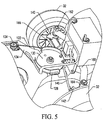
- FIG. 5 illustrates a perspective view of portions of the cable system 100 from the side of the riding lawn care vehicle 10 to show the cable system 100 within the context of other components according to an example embodiment.
- the view shown in FIG. 5 is a side view with selected components removed.
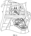
- FIG. 6 illustrates a perspective view of portions of the cable system 100 looking from the vehicle rear toward the steering column 37 with selected components removed.
- cable system 100 may include a cable 110 that may wrap at least partially around a steering column pulley 120 attached to a distal end of the steering column 37.
- the steering column pulley 120 may frictionally engage the cable 110 such that when the steering column pulley 120 is rotated (e.g., responsive to rotation of the steering wheel 36), the cable 110 is pulled through the steering column pulley 120 in the same direction as the direction of rotation of the steering wheel 36.
- FIG. 4 illustrates an example in which the turn ratio for the steering wheel 36 and the steering column pulley 120 is 1 : 1, other embodiments may employ gears and/or the like to adjust the turn ratio, if desired.
- a substantially equal amount of the cable 110 may be disposed on each side of the steering column pulley 120 when the steering wheel 37 is in a neutral or twelve o'clock position.
- a portion of the cable 110 that is pulled when the steering wheel is turned clockwise may be referred to as a first cable portion 122 and a portion of the cable 110 that is pulled when the steering wheel 36 is turned counterclockwise may be referred to as a second cable portion 124.
- the first and second cable portions 122 and 124 may be portions of the same unitary cable in some cases. However, in other cases, the first and second cable portions 122 and 124 may be distinct portions that may be joined together or have the ends thereof fixed to the steering column pulley 120 proximate to each other.
- first cable portion 122 and second cable portion 124 may terminate at respective cable connectors (e.g., first cable connector 126 and second cable connector 128).
- the first and second cable connectors 126 and 128 may then engage a steering disc 130 (see FI G. 5), which may be located substantially between the rear wheels 32.
- the first cable portion 122 and the second cable portion 124 may each be run from the steering column pulley 120 (which may be located proximate to a front end of the riding lawn care vehicle 10) back to the steering disc 130 along one side of the riding lawn care vehicle 10 using a single cable-conveying pulley assembly 131 disposed along the corresponding one side of the riding lawn care vehicle 10.
- FIGS. 5 and 6 illustrate the first and second cable portions 122 and 124 running down the right side of the riding lawn care vehicle 10, and the pulley assembly 131 therefore also being disposed on the right side of the riding lawn care vehicle 10
- alternative embodiments may run the first and second cable portions 122 and 124 down the left side of the riding lawn care vehicle 10 (or the middle portion thereof).
- the pulley assembly 131 may include a front double pulley 132 and a back double pulley 134 that are each disposed along a same side of the riding lawn care vehicle 10 to handle the cable system 100 and convey portions thereof rearward for communication with the steering disc 130.
- each of the front double pulley 132 and the back double pulley 134 may include two wheels mounted to the same shaft (or different shafts that are aligned with each other). As such, the wheels of each double pulley may be enabled to move independently of each other, and therefore in opposite directions to support the pull action on one cable portion (e.g., the first cable portion 122) and a corresponding push action on the other cable portion (e.g., the second cable portion 124). As shown in FIGS. 4-6 , the front double pulley 132 may consolidate handling both the first cable portion 122 and the second cable portion 124 for passage rearward to the back double pulley 134 using one pulley.
- the back double pulley 134 may also consolidate handling of the first and second cable portions 122 and 124 at a single component, but may further provide a fixed point from which the first cable portion 122 and the second cable portion 124 may diverge to engage opposite sides of the steering disc 130. Accordingly, both cables that provide inputs for pulling or otherwise changing the orientation of the steering disc 130 may be communicated back toward a rear of the riding lawn care vehicle 10 from the steering wheel 36 using the pulley assembly 131 disposed along one side of the riding lawn care vehicle 10. As shown in FIG. 4 , an axis of the front double pulley 132 may be oriented differently than an axis of the back double pulley 134 and an axis of the steering column pulley 120.
- the orientations of each of the pulleys may be selected to enable the first and second cable portions 122 and 124 to be conveyed back from the steering column pulley 120 to the steering disc 130 without the first and second cable portions coming into contact with each other even though their positions relative to each other swap (i.e., the cables cross) as they are conveyed back to the steering disc 130.
- the steering disc 130 may have a fixed axis of rotation, but may be allowed to rotate responsive to the cable 110 being pulled in either direction based on rotation of the steering wheel 36 via communication of a corresponding pull action via the pulley assembly 131.
- a size of the steering disc 130 may be selected based on the size of the steering column pulley 120 such that a certain amount of rotation of the steering column pulley 120 causes a corresponding known amount of rotation of the steering disc 130, when the first and second cable portions 122 and 124 move, based on the ratio of sizes of the steering column pulley 120 and the steering disc 130.
- the steering disc 130 may be connected to a first steering knuckle 140 and a second steering knuckle 142 via a first tie rod 144 and a second tie rod 146, respectively.
- the first and second steering knuckles 140 and 142 may each be affixed to corresponding ones of a first axle rod 150 and a second axle rod 152.
- the first and second axle rods 150 and 152 may be rotatably mounted to opposite ends of an axle mount 160 that may form a portion of the frame 70, or may be connected to the frame 70.
- the axle mount 160 may extend substantially perpendicularly to the longitudinal length of the riding lawn care vehicle 10 substantially between the rear wheels 32.
- the rear wheels 32 may be affixed to the first and second axle rods 150 and 152, respectively.
- the axle mount 160 may be structured as a single assembly, weldment, rod, tube or other support structure having a first distal end that rotatably engages the first axle rod 150 and a second distal end that rotatably engages the second axle rod 152.
- the first and second distal ends of the axle mount 160 may terminate in respective first and second sleeves 162 and 164.
- the first and second sleeves 162 and 164 may receive the first and second axle rods 150 and 152, respectively, therein.
- first and second sleeves 162 and 164 may further include bearings (e.g., a bushing, ball bearing or journal bearing) to facilitate rotational relative motion between the first and second sleeves 162 and 164 and the first and second axle rods 150 and 152, respectively.
- bearings e.g., a bushing, ball bearing or journal bearing
- first and second steering knuckles 140 and 142 may be relatively mirror image reproductions of each other oriented to operate on opposite sides of the riding lawn care vehicle 10.
- first and second axle rods 150 and 152 may be relatively mirror image reproductions of each other oriented to operate on opposite sides of the riding lawn care vehicle 10. Accordingly, for purposes of explanation, the first steering knuckle 140 and the first axle rod 150 will be described in greater detail below, but it should be appreciated that the second steering knuckle 142 and the second axle rod 150 are structured and function similarly (albeit for an opposite side of the riding lawn care vehicle 10).
- the first steering knuckle 140 may be affixed to the first axle rod 150 proximate to a bottom portion of the first sleeve 162.
- the first steering knuckle 140 may, in some cases, be a bracket formed from sheet metal or another rigid material and may extend around all sides of the first axle rod 150. As such, a substantial portion of the first steering knuckle 140 may lie in a single plane, which may be perpendicular to the longitudinal length of the first sleeve 162.
- the first steering knuckle 140 may include a receiving opening at a portion thereof to receive a rotatable pin that may connect the first tie rod 144 to the first steering knuckle 140 in a rotatable manner.
- the receiving opening may be positioned at a protruded portion of the first steering knuckle 140 which may be oriented substantially toward either the front or the back of the riding lawn care vehicle 10.
- a force may be exerted through the rotatable pin onto the first steering knuckle 140.
- the first axle rod 150 may then be caused to rotate within the first sleeve 162 based on the direction of the force imparted by the first tie rod 144.
- first or second tie rods 144 or 146 may be pushed and the other of the first or second tie rods 144 or 146 may be pulled responsive to rotation of the steering disc 130.
- the steering disc 130 may be disposed substantially along a longitudinal centerline of the riding lawn care vehicle 10.
- the first and second tie rods 144 and 146 may each be connected to the steering disc 130 relatively proximate to each other.
- the first and second tie rods 144 and 146 may connect to the steering disc 130 proximate to the twelve o'clock position (e.g., at the eleven o'clock and one o'clock positions, respectively). The first and second tie rods 144 and 146 may then extend away from the steering disc 130 in relatively opposite directions to engage the first and second steering knuckles 140 and 142, respectively.
- first and second steering knuckles 140 and 142 are affixed to the first and second axle rods 150 and 152, and the first and second axle rods 150 and 152 are rotatably mounted to the axle mount 160, movement of the first and second steering knuckles 140 and 142 responsive to rotation of the steering disc 130 causes a corresponding rotation (in the same direction) of the first and second axle rods 150 and 152.
- first cable portion 122 may be pulled toward the steering column pulley 120 and the first cable connector 126 may also be pulled and thereby initiate rotation of the steering disc 130.
- the steering disc 130 may rotate in a counter-clockwise direction. Such rotation of the steering disc 130 may cause the first tie rod 144 to push on the first steering knuckle 140 to impart a force on the first steering knuckle 140 to initiate a counter-clockwise rotation of the first axle rod 150 within the first sleeve 162. The counter-clockwise rotation of the first axle rod 150 may correspondingly turn the back right wheel of the riding lawn care vehicle 10 inward (or toward the left).
- rotation of the steering disc 130 in the counter-clockwise direction may also cause the second tie rod 146 to push on the second steering knuckle 142 to impart a force on the second steering knuckle 142 to initiate a counter-clockwise rotation of the second axle rod 152 within the second sleeve 164.
- the counter-clockwise rotation of the second axle rod 152 may correspondingly turn the back left wheel of the riding lawn care vehicle 10 outward (or toward the left).
- first and second axle rods 150 and 152 may be further provided to initiate changes to the camber angle of the rear wheels 32 responsive to steering inputs to the right or left.
- the first and second axle rods 150 and 152 may be constructed to have at least two linear portions that are connected to each other by a bent portion 180.
- the two linear portions may include a spindle or top portion 182 that is inserted into one of the sleeves (e.g., the first sleeve 162 or the second sleeve 164) for rotatable connection therewith, and an axle or bottom portion 184 to which one of the rear wheels 32 is rotatably attached.
- the bent portion 180 may be formed such that the top portion 182 may form an obtuse angle with respect to the bottom portion 184.
- an angle formed between a longitudinal length of the sleeves and the longitudinal length of the axle mount 160 may be set such that, when the rear wheels 32 are straightened (e.g., due to the steering wheel 36 being oriented at the twelve o'clock position), a longitudinal length of the bottom portion 184 is substantially parallel to the driving surface or ground and the camber angle of the corresponding wheel is substantially zero.
- the top portion 182 may rotate within the corresponding one of the sleeves (e.g., the first sleeve 162 or the second sleeve 164) and the camber angle may be adjusted to a non-zero value.
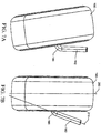
- FIG. 7 which includes FIGS. 7A and 7B , illustrates a wheel 190 (e.g., the right rear wheel) in both a zero camber angle state (e.g., when the steering wheel 36 is at the twelve o'clock position as shown in FIG. 7B ) and a positive camber angle state (e.g., when the steering wheel 36 is rotated to provide a steering input to the right or left as shown in FIG. 7A ).
- the camber angle is generally considered to be the angle made between the wheels and riding lawn care vehicle 10, or more specifically, the angle between the vertical axis of the wheels and the vertical axis of the riding lawn care vehicle 10 when viewed from the front or rear.
- the top 192 of the wheel 190 is farther out than the bottom 194 of the wheel 190 to define a positive camber.
- a wheel centerline 200 may be defined relative to the radial dimensions of the wheel through a center of the tread portion of the wheel 190. As such, the wheel centerline 200 may bisect the axis of rotation of the wheel 190.
- the wheel center line 200 When the steering wheel 36 is in a neutral position (e.g., without any right or left steering input being inserted via rotation of the steering wheel 36 out of the twelve o'clock position), the wheel center line 200 may be substantially perpendicular to the driving surface or ground. Meanwhile, a spindle centerline 210 corresponding to a line drawn through the longitudinal center of the top portion 182 may extend toward the wheel centerline 200 to intersect the wheel centerline 200 at a position below the wheel 190. In some cases, it may be desirable for the wheel centerline 200 and the spindle centerline 210 to intersect below the wheel 190, but proximate to the surface of the wheel 190. Accordingly, the width of the wheel 190 may dictate the angle between the top portion 182 and the bottom portion 184.
- the bent portion 180 may be made such that the angle between the top portion 182 and the bottom portion 184 increases in order to provide desirable camber angle changes when non-neutral steering inputs are provided.
- the spindle centerline 210 when viewed from the side of the riding lawn care vehicle 10, the spindle centerline 210 may be substantially perpendicular to the driving surface or ground. Moreover, since the top portion 182 rotates within the sleeve, which is fixed relative to the frame 70 by attachment to the axle mount 160, the top portion 182 is maintained such that the spindle centerline 210 is perpendicular to the driving surface or ground when viewed from the side even when the top portion 182 is rotated. However, given that the top portion 182 rotates responsive to steering inputs to insert a camber angle when the steering wheel 36 is rotated out of the neutral position, it should be appreciated that the camber angle may increase as the amount of deflection from the neutral position increases.
- the camber angle may decrease until the neutral position is reached.
- the camber angle may be zero. If the steering wheel 36 is further rotated counter-clockwise to a full left turn, the camber angle will increase from zero at the neutral position to some maximum value at the full left turn position.
- An example embodiment may provide for conveying steering inputs from a steering wheel or other steering input device to rear wheels using a cable system that runs cable down only one side of the riding lawn care vehicle.
- the engine e.g., engine 60
- the engine 60 may be disposed between the front and back wheels (see FIG. 1 ).
- the engine 60 may be more specifically disposed under the seat 20 and between the steering column 37 and the steering disc 130.
- the cables may extend around one side of the engine 60 in this configuration.
- a battery for powering some components of the riding lawn care vehicle 10 may also be provided.
- the battery may be provided between the rear wheels 32 (e.g., over the axle mount 160).
- Such configuration may, in some cases, provide weight over the rear wheels 32 to facilitate steering functionality given that the engine 60 and the weight associated therewith may be moved forward of the rear wheels 32.
Description
- Example embodiments generally relate to lawn care vehicles and, more particularly, relate to steering assembly for vehicles configured for performing lawn maintenance with rear wheel steering.
- Lawn care tasks are commonly performed using various tools and/or machines that are configured for the performance of corresponding specific tasks. Certain tasks, like grass cutting, are typically performed by lawn mowers. Lawn mowers themselves may have many different configurations to support the needs and budgets of consumers. Walk-behind lawn mowers are typically compact, have comparatively small engines (e.g., less than 200 cubic centimeters (cc)) and are relatively inexpensive. Meanwhile, at the other end of the spectrum, riding lawn mowers, such as lawn tractors, can be quite large and sometimes have engines exceeding 400 cc. Riding lawn mowers can sometimes also be configured with various functional accessories (e.g., trailers, tillers and/or the like) in addition to grass cutting components. Riding lawn mowers provide the convenience of a riding vehicle as well as a typically larger cutting deck as compared to a walk-behind model.
- By their very nature, riding lawn mowers include steering assemblies that are used to direct the movement of the riding lawn mowers. The steering assemblies often take the familiar form of a steering wheel. However, handlebar assemblies have also been used in some cases. More recently, some zero turn mowers have employed separate steering levers or even a joystick to provide steering functionality. There are clearly a number of steering assembly options from which to choose when an operator considers purchasing a riding lawn mower based on performance criteria, budget restrictions, or personal preference. However, each different type of steering assembly has corresponding different technical challenges associated therewith.
- The document
US 4,367,881 discloses a steering system for a riding lawn mower that includes a rotatable steering control member located remotely from a steerable dirigible wheel unit, a drive sprocket mounted for common rotation with the steering control member, a short length of roller or sprocket chain trained about the drive sprocket, a driven sprocket mounted for comment rotation with the dirigible wheel unit, a short length of roller of sprocket chain trained about the driven sprocket, and flexible members such as wire cables, interconnecting the chains so that the driven sprocket is rotated in response to rotation of the drive sprocket. Two sets of coaxially aligned pairs of pulley are located between the drive and driven sprockets and the cables are trained over the same sides of the pulleys in each set and are thereby are guided through a circuitous route between the sprockets. One set of pulleys is adjustably mounted relative to the cables for adjusting the tension applied on the cables to remove slack therefrom. - The document
EP 0 672 575 A1 discloses a car for town runs with two front directing wheels and two rear tractor wheels. The car comprises forks that are linked to a platform through single fifth wheels with vertical axes. The rotating area of the fifth wheel of every front wheel is integral to a radial arm. Said arms are articulated on the ends of lever constituted by two tie rods with faced ends connected to a part through an adjustment joint of virtual cocking of two tie rods. The part is articulated versus another part and is integral to a groove pulley. On the groove, in a riding position, there is a cable. Said cable is anular and, through return pulleys with a dual turn, engages pulley integral to the steering pulley and to the steering wheel. - According to the invention, a riding lawn care vehicle is provided. The riding lawn care vehicle comprises a frame and a steering assembly. Wheels of the riding lawn care vehicle are operably coupled to the frame. The steering assembly comprises a steering wheel operably coupled to rear wheels of the riding lawn care vehicle via a cable system. The cable system comprises a first cable portion, a second cable portion and a pulley assembly. The first and second cable portions each are operably coupled to a steering column pulley at respective first ends of the first and second cable portions. The steering column pulley is configured to pull a corresponding one of the first cable portion or the second cable portion based on a direction of rotation of the steering wheel. The first and second cable portions each are operably coupled to a steering disc at respective second ends of the first and second cable portions. The steering disc is configured to provide translation of movement of the first cable portion and the second cable portion into corresponding movement of the rear wheels. The pulley assembly comprises a first pulley and a second pulley in which each of the first pulley and the second pulley of the pulley assembly handles both the first cable portion and the second cable portion as the first cable portion and the second cable portion are conveyed rearward toward the steering disc to translate motion of the steering column pulley to the steering disc.
- Accordingly, in order to improve space efficiency with respect to provision of the steering assembly a steering system employs steering cables that run along a single side of the lawn care vehicle. By running cables down a single side of the lawn care vehicle, a reduction in both the space consumed and the number of parts that are required for implementation of the steering functionality of the rear wheel steering embodiment may be achieved.
- The cable system provides operable coupling between a steering wheel of a riding lawn care vehicle and rear wheels of the riding lawn care vehicle. The cable system includes a first cable portion, a second cable portion and a pulley assembly. The first and second cable portions each contact a steering column pulley at respective first ends of the first and second cable portions. The steering column pulley is configured to pull a corresponding one of the first cable portion or the second cable portion based on a direction of rotation of the steering wheel. The first and second cable portions each are in operable communication with a steering disc at respective second ends of the first and second cable portions. The steering disc provides translation of movement of the first cable portion and the second cable portion into corresponding movement of the rear wheels. The pulley assembly is configured such that each pulley of the pulley assembly handles both the first cable portion and the second cable portion as the first cable portion and the second cable portion are conveyed from the steering column pulley to the steering disc to translate motion of the steering column pulley to the steering disc.
- Embodiments improve space efficiency of a riding lawn care vehicle and allow manufacturers to more efficiently design and produce such vehicles.
- Having thus described the invention in general terms, reference will now be made to the accompanying drawings, which are not necessarily drawn to scale, and wherein:
-
FIG. 1A illustrates a perspective view of a riding lawn care vehicle according to an example embodiment; - FIG. IB illustrates a top view of the riding lawn care vehicle according to an example embodiment;
-
FIG. 2 illustrates portions of a cutting deck of the riding lawn care vehicle according to an example embodiment; -
FIG. 3 illustrates a perspective view of a cutting unit lifting controller of the riding lawn care vehicle according to an example embodiment; -
FIG. 4A illustrates a perspective view from the side of a cable system of the riding lawn care vehicle according to an example embodiment; -
FIG. 4B illustrates a perspective view from the back looking down onto the cable system according to an example embodiment; -
FIG. 5 illustrates a perspective view of portions of the cable system from the side of the riding lawn care vehicle to show the cable system within the context of other components according to an example embodiment; -
FIG. 6 illustrates a perspective view of portions of the cable system looking from the vehicle rear toward a steering column with selected components removed according to an example embodiment; -
FIG. 7A illustrates a wheel in a positive camber angle state responsive to a steering wheel being rotated out of a neutral position to provide a steering input to the right or left according to an example embodiment; and -
FIG. 7B illustrates the wheel in a zero camber angle state responsive to the steering wheel being at the twelve o'clock position according to an example embodiment. - Some example embodiments now will be described more fully hereinafter with reference to the accompanying drawings, in which some, but not all example embodiments are shown. Indeed, the examples described and pictured herein should not be construed as being limiting as to the scope, applicability or configuration of the present disclosure. Rather, these example embodiments are provided so that this disclosure will satisfy applicable legal requirements. Like reference numerals refer to like elements throughout. Furthermore, as used herein, the term "or" is to be interpreted as a logical operator that results in true whenever one or more of its operands are true. As used herein, operable coupling should be understood to relate to direct or indirect connection that, in either case, enables functional interconnection of components that are operably coupled to each other.
- Some example embodiments may improve space efficiency with respect at least to the implementation of steering functionality of lawn care vehicles such as, for example, riding lawn mowers. In this regard, for example, some embodiments may employ a cable system to support rear wheel steering functionality, but may run the cable system only on one side of the lawn care vehicle. As such, since the cables only run down one side of the lawn care vehicle, less space may be consumed by the cable system and fewer components may be used to support the operation of the cable system.
-
FIG. 1 , which includesFIGS. 1A and1B , illustrates a ridinglawn care vehicle 10 having a rear wheel steering assembly according to an example embodiment. In this regard,FIG. 1A illustrates a perspective view of the ridinglawn care vehicle 10 according to an example embodiment, and FIG. IB illustrates a top view of the ridinglawn care vehicle 10 according to an example embodiment. In some embodiments, the ridinglawn care vehicle 10 may includeseat 20 that may be disposed at a center, rear or front portion of the ridinglawn care vehicle 10. The ridinglawn care vehicle 10 may also include a steering assembly 30 (e.g., a steering wheel, handle bars, or the like) functionally connected torear wheels 32 of the ridinglawn care vehicle 10 to allow the operator to steer the ridinglawn care vehicle 10. Since steering control is provided to therear wheels 32, thefront wheels 34 may not receive steering inputs in some embodiments. The operator may sit on theseat 20, which may be disposed to the rear of thesteering assembly 30 to provide input for steering of the ridinglawn care vehicle 10 via thesteering assembly 30. - In an example embodiment, the steering
assembly 30 may include asteering wheel 36 and asteering column 37. Thesteering column 37 may operably connect to additional steering assembly components described in greater detail below. Moreover, in some embodiments, thesteering column 37 may extend into asteering console 38, which may provide a cover to improve the aesthetic appearance of the ridinglawn care vehicle 10 by obscuring the view of various mechanical components associated with the steeringassembly 30. The ridinglawn care vehicle 10 may also include additional control related components such as one ormore speed controllers 40, cuttingheight adjuster 42 and/or cuttingunit lifting controller 44. Some of the controllers, such as thespeed controllers 40 and the cuttingunit lifting controller 44, may be provided in the form of foot pedals that may sit proximate to a footrest 46 (which may include a portion on both sides of the riding lawn care vehicle 10 (e.g., on opposite sides of the steering console 38) to enable the operator to rest his or her feet thereon while seated in theseat 20. - The riding
lawn care vehicle 10 may also include, or be configured to support attachment of, a cuttingdeck 50 having at least one cutting blade mounted therein.FIG. 2 illustrates portions of the cuttingdeck 50 according to an example embodiment. The cuttingdeck 50 may be a removable attachment that may be positioned in front of thefront wheels 34 in a position to enable the operator to cut grass using the cutting blade when the cutting blade is rotated below the cuttingdeck 50 and the cuttingdeck 50 is in a cutting position. When operating to cut grass, the grass clippings may be captured by a collection system, mulched, or expelled from the cuttingdeck 50 via either a side discharge or a rear discharge. - In an example embodiment, the cutting
deck 50 may be elevated or lifted out of direct contact with the ground via the cuttingunit lifting controller 44, a portion of which is shown in greater detail inFIG. 3 . In this regard, the cuttingunit lifting controller 44 may be a foot pedal that operates linkages to lift the cuttingdeck 50 upward. Lifting the cuttingdeck 50 may enable the ridinglawn care vehicle 10 to traverse certain rough terrain or obstacles (e.g., small rocks, curbs, or other features) or may otherwise be preferable for some operators when in a transit mode, or when the ridinglawn care vehicle 10 is not actively being used in a cutting operation. The height of the blades within the cuttingdeck 50 may also be adjusted using the cuttingheight adjuster 42. In this regard, the cuttingheight adjuster 42 may be a lever that is operably connected to the blades via linkages (not shown) to adjust the height of the blades relative to the ground when the cuttingdeck 50 is lowered into a cutting position. In some embodiments, the cuttingdeck 50 itself may includewheels 52 to help ensure that the cuttingdeck 50 stays relatively level during operation to provide an even cut. -
FIG. 3 illustrates a perspective view of the cuttingunit lifting controller 44 according to an example embodiment. As shown inFIG. 3 , the cuttingunit lifting controller 44 may be provided as a pedal. Of note, althoughFIGS. 1 and3 illustrate the cuttingunit lifting controller 44 being on the left side of thesteering console 38, it could alternatively be on the right side or even at some other location in other example embodiments. In some embodiments, thesteering console 38 may also improve the aesthetic appearance of the ridinglawn care vehicle 10 by obscuring the view of various mechanical components associated with the operation of the cuttingunit lifting controller 44 for lifting and/or holding the cuttingdeck 50. In an example embodiment, when the cuttingunit lifting controller 44 is depressed or pushed down (e.g., toward the footrest 46), the cuttingdeck 50 may be elevated (e.g., such that thewheels 52 are lifted off the ground). In some cases, the cuttingdeck 50 may remain elevated for the duration of any period during which the cuttingunit lifting controller 44 is depressed. However, in other examples, a liftinglock 54 may be provided to enable locking the cuttingunit lifting controller 44 in a locked position as described in greater detail below. The liftinglock 54 may be positioned on thesteering console 38 in some embodiments. However, other locations may be utilized in alternate embodiments. - In embodiments in which the cutting
deck 50 is removable, the cuttingdeck 50 may include blade drive components (e.g., belts, pulleys or other components, some of which are visible inFIG. 2 ) of the cuttingdeck 50 that may facilitate cutting using the cuttingdeck 50 during operation. The cuttingdeck 50 may also include a cuttingdeck mounting assembly 58 configured to mate with the ridinglawn care vehicle 10 to join the cuttingdeck 50 to the ridinglawn care vehicle 10. Of note,FIG. 1A and FIG. IB illustrate the ridinglawn care vehicle 10 with the cuttingdeck 50 removed. However, it should be appreciated that the cuttingdeck 50 may be attached as described above, and then lifted in some cases, as described herein. - In the pictured example embodiment of
FIG. 1 , anengine 60 of the ridinglawn care vehicle 10 is disposed substantially below a seated operator. However, in other example embodiments, theengine 60 could be in different positions such as in front of or behind the operator. In some embodiments, theengine 60 may be operably coupled to one or more of the wheels of the ridinglawn care vehicle 10 in order to provide drive power for the ridinglawn care vehicle 10. In some embodiments, theengine 60 may be capable of powering two wheels, while in others, theengine 60 may power all four wheels of the ridinglawn care vehicle 10. Moreover, in some cases, theengine 60 may manually or automatically shift between powering either two wheels or all four wheels of the ridinglawn care vehicle 10. Theengine 60, the steeringassembly 30, the cuttingdeck 50, theseat 20 and other components of the ridinglawn care vehicle 10 may be operably connected (directly or indirectly) to aframe 70 of the ridinglawn care vehicle 10. Theframe 70 may be a rigid structure configured to provide support, connectivity and interoperability functions for various ones of the components of the ridinglawn care vehicle 10. In some embodiments, theframe 70 may be split or articulated such that, for example, thefront wheels 34 are disposed on an opposite portion of theframe 70 than the portion of the frame on which theback wheels 32 are disposed with respect to an articulated joint in theframe 70. - In some example embodiments, the steering
assembly 30 may be embodied as an assembly of metallic or other rigid components that may be welded, fitted, bolted or otherwise operably coupled to each other and coupled to the wheels (rear wheels 32 in this example) of the ridinglawn care vehicle 10 to which steering inputs are provided. For example, the steeringassembly 30 may include or otherwise be coupled with a steering cable assembly to translate rotational motion applied to the steering assembly 30 (and more particularly to the steering wheel 36) into directional inputs to orient the wheels accordingly. Other steering control systems may be employed in some alternative embodiments. -
FIGS. 4-6 illustrate more detailed views of some portions of thesteering assembly 30 to illustrate an example embodiment. In this regard,FIG. 4 , which includesFIGS. 4A and4B , illustrates isolated perspective views of thesteering assembly 30 according to an example embodiment. Other components have been removed from the views inFIG. 4 in order to facilitate a clear and concise description of thecable system 100 of an example embodiment.FIG. 4A illustrates a perspective view from the side of thecable system 100 andFIG. 4B illustrates a perspective view from the back looking down onto thecable system 100.FIG. 5 illustrates a perspective view of portions of thecable system 100 from the side of the ridinglawn care vehicle 10 to show thecable system 100 within the context of other components according to an example embodiment. In this regard, the view shown inFIG. 5 is a side view with selected components removed. Meanwhile,FIG. 6 illustrates a perspective view of portions of thecable system 100 looking from the vehicle rear toward thesteering column 37 with selected components removed. - Referring now to
FIGS. 4-6 ,cable system 100 may include acable 110 that may wrap at least partially around asteering column pulley 120 attached to a distal end of thesteering column 37. Thesteering column pulley 120 may frictionally engage thecable 110 such that when thesteering column pulley 120 is rotated (e.g., responsive to rotation of the steering wheel 36), thecable 110 is pulled through thesteering column pulley 120 in the same direction as the direction of rotation of thesteering wheel 36. AlthoughFIG. 4 illustrates an example in which the turn ratio for thesteering wheel 36 and thesteering column pulley 120 is 1 : 1, other embodiments may employ gears and/or the like to adjust the turn ratio, if desired. - In an example embodiment, a substantially equal amount of the
cable 110 may be disposed on each side of thesteering column pulley 120 when thesteering wheel 37 is in a neutral or twelve o'clock position. For purposes of explanation, a portion of thecable 110 that is pulled when the steering wheel is turned clockwise may be referred to as afirst cable portion 122 and a portion of thecable 110 that is pulled when thesteering wheel 36 is turned counterclockwise may be referred to as asecond cable portion 124. The first andsecond cable portions second cable portions steering column pulley 120 proximate to each other. Distal ends of thefirst cable portion 122 andsecond cable portion 124 may terminate at respective cable connectors (e.g.,first cable connector 126 and second cable connector 128). The first andsecond cable connectors rear wheels 32. - In an example embodiment, the
first cable portion 122 and thesecond cable portion 124 may each be run from the steering column pulley 120 (which may be located proximate to a front end of the riding lawn care vehicle 10) back to thesteering disc 130 along one side of the ridinglawn care vehicle 10 using a single cable-conveyingpulley assembly 131 disposed along the corresponding one side of the ridinglawn care vehicle 10. AlthoughFIGS. 5 and6 illustrate the first andsecond cable portions lawn care vehicle 10, and thepulley assembly 131 therefore also being disposed on the right side of the ridinglawn care vehicle 10, alternative embodiments may run the first andsecond cable portions second cable portions pulley assembly 131 may include a frontdouble pulley 132 and a backdouble pulley 134 that are each disposed along a same side of the ridinglawn care vehicle 10 to handle thecable system 100 and convey portions thereof rearward for communication with thesteering disc 130. - In some embodiments each of the front
double pulley 132 and the backdouble pulley 134 may include two wheels mounted to the same shaft (or different shafts that are aligned with each other). As such, the wheels of each double pulley may be enabled to move independently of each other, and therefore in opposite directions to support the pull action on one cable portion (e.g., the first cable portion 122) and a corresponding push action on the other cable portion (e.g., the second cable portion 124). As shown inFIGS. 4-6 , the frontdouble pulley 132 may consolidate handling both thefirst cable portion 122 and thesecond cable portion 124 for passage rearward to the backdouble pulley 134 using one pulley. The backdouble pulley 134 may also consolidate handling of the first andsecond cable portions first cable portion 122 and thesecond cable portion 124 may diverge to engage opposite sides of thesteering disc 130. Accordingly, both cables that provide inputs for pulling or otherwise changing the orientation of thesteering disc 130 may be communicated back toward a rear of the ridinglawn care vehicle 10 from thesteering wheel 36 using thepulley assembly 131 disposed along one side of the ridinglawn care vehicle 10. As shown inFIG. 4 , an axis of the frontdouble pulley 132 may be oriented differently than an axis of the backdouble pulley 134 and an axis of thesteering column pulley 120. In an example embodiment, the orientations of each of the pulleys may be selected to enable the first andsecond cable portions steering column pulley 120 to thesteering disc 130 without the first and second cable portions coming into contact with each other even though their positions relative to each other swap (i.e., the cables cross) as they are conveyed back to thesteering disc 130. - The
steering disc 130 may have a fixed axis of rotation, but may be allowed to rotate responsive to thecable 110 being pulled in either direction based on rotation of thesteering wheel 36 via communication of a corresponding pull action via thepulley assembly 131. In an example embodiment, a size of thesteering disc 130 may be selected based on the size of thesteering column pulley 120 such that a certain amount of rotation of thesteering column pulley 120 causes a corresponding known amount of rotation of thesteering disc 130, when the first andsecond cable portions steering column pulley 120 and thesteering disc 130. Thesteering disc 130 may be connected to afirst steering knuckle 140 and asecond steering knuckle 142 via afirst tie rod 144 and asecond tie rod 146, respectively. The first andsecond steering knuckles first axle rod 150 and asecond axle rod 152. The first andsecond axle rods axle mount 160 that may form a portion of theframe 70, or may be connected to theframe 70. Theaxle mount 160 may extend substantially perpendicularly to the longitudinal length of the ridinglawn care vehicle 10 substantially between therear wheels 32. Therear wheels 32 may be affixed to the first andsecond axle rods - In some examples, the
axle mount 160 may be structured as a single assembly, weldment, rod, tube or other support structure having a first distal end that rotatably engages thefirst axle rod 150 and a second distal end that rotatably engages thesecond axle rod 152. In some embodiments, the first and second distal ends of theaxle mount 160 may terminate in respective first andsecond sleeves second sleeves second axle rods second sleeves second sleeves second axle rods - In an example embodiment, first and
second steering knuckles lawn care vehicle 10. Similarly, the first andsecond axle rods lawn care vehicle 10. Accordingly, for purposes of explanation, thefirst steering knuckle 140 and thefirst axle rod 150 will be described in greater detail below, but it should be appreciated that thesecond steering knuckle 142 and thesecond axle rod 150 are structured and function similarly (albeit for an opposite side of the riding lawn care vehicle 10). - The
first steering knuckle 140 may be affixed to thefirst axle rod 150 proximate to a bottom portion of thefirst sleeve 162. Thefirst steering knuckle 140 may, in some cases, be a bracket formed from sheet metal or another rigid material and may extend around all sides of thefirst axle rod 150. As such, a substantial portion of thefirst steering knuckle 140 may lie in a single plane, which may be perpendicular to the longitudinal length of thefirst sleeve 162. In some embodiments, thefirst steering knuckle 140 may include a receiving opening at a portion thereof to receive a rotatable pin that may connect thefirst tie rod 144 to thefirst steering knuckle 140 in a rotatable manner. The receiving opening may be positioned at a protruded portion of thefirst steering knuckle 140 which may be oriented substantially toward either the front or the back of the ridinglawn care vehicle 10. By orienting the receiving opening accordingly, when thefirst tie rod 144 pushes or pulls responsive to rotation of thesteering disc 130, a force may be exerted through the rotatable pin onto thefirst steering knuckle 140. Thefirst axle rod 150 may then be caused to rotate within thefirst sleeve 162 based on the direction of the force imparted by thefirst tie rod 144. - During a turn, dependent upon which way the
steering disc 130 turns, one of the first orsecond tie rods second tie rods steering disc 130. Thesteering disc 130 may be disposed substantially along a longitudinal centerline of the ridinglawn care vehicle 10. In an example embodiment, the first andsecond tie rods steering disc 130 relatively proximate to each other. For example, if an after portion of thesteering disc 130 that is oriented in line with the centerline of the ridinglawn care vehicle 10 is considered to be the twelve o'clock position, the first andsecond tie rods steering disc 130 proximate to the twelve o'clock position (e.g., at the eleven o'clock and one o'clock positions, respectively). The first andsecond tie rods steering disc 130 in relatively opposite directions to engage the first andsecond steering knuckles - Since the first and
second steering knuckles second axle rods second axle rods axle mount 160, movement of the first andsecond steering knuckles steering disc 130 causes a corresponding rotation (in the same direction) of the first andsecond axle rods steering wheel 36 is turned in the clockwise direction, thefirst cable portion 122 may be pulled toward thesteering column pulley 120 and thefirst cable connector 126 may also be pulled and thereby initiate rotation of thesteering disc 130. In this example, when thesteering wheel 36 is turned clockwise (presumably to initiate a turn to the right), therear wheels 32 would need to be caused to turn to be oriented to the left since rear wheel steering is employed. Accordingly, when thefirst cable connector 126 pulls on thesteering disc 130, thesteering disc 130 may rotate in a counter-clockwise direction. Such rotation of thesteering disc 130 may cause thefirst tie rod 144 to push on thefirst steering knuckle 140 to impart a force on thefirst steering knuckle 140 to initiate a counter-clockwise rotation of thefirst axle rod 150 within thefirst sleeve 162. The counter-clockwise rotation of thefirst axle rod 150 may correspondingly turn the back right wheel of the ridinglawn care vehicle 10 inward (or toward the left). Similarly, rotation of thesteering disc 130 in the counter-clockwise direction may also cause thesecond tie rod 146 to push on thesecond steering knuckle 142 to impart a force on thesecond steering knuckle 142 to initiate a counter-clockwise rotation of thesecond axle rod 152 within thesecond sleeve 164. The counter-clockwise rotation of thesecond axle rod 152 may correspondingly turn the back left wheel of the ridinglawn care vehicle 10 outward (or toward the left). - In an example embodiment, the first and
second axle rods rear wheels 32 responsive to steering inputs to the right or left. In this regard, for example, the first andsecond axle rods bent portion 180. The two linear portions may include a spindle ortop portion 182 that is inserted into one of the sleeves (e.g., thefirst sleeve 162 or the second sleeve 164) for rotatable connection therewith, and an axle orbottom portion 184 to which one of therear wheels 32 is rotatably attached. In an example embodiment, thebent portion 180 may be formed such that thetop portion 182 may form an obtuse angle with respect to thebottom portion 184. Moreover, in some embodiments, an angle formed between a longitudinal length of the sleeves and the longitudinal length of theaxle mount 160 may be set such that, when therear wheels 32 are straightened (e.g., due to thesteering wheel 36 being oriented at the twelve o'clock position), a longitudinal length of thebottom portion 184 is substantially parallel to the driving surface or ground and the camber angle of the corresponding wheel is substantially zero. However, as a steering input is inserted by rotation of thesteering wheel 36, thetop portion 182 may rotate within the corresponding one of the sleeves (e.g., thefirst sleeve 162 or the second sleeve 164) and the camber angle may be adjusted to a non-zero value. -
FIG. 7 , which includesFIGS. 7A and 7B , illustrates a wheel 190 (e.g., the right rear wheel) in both a zero camber angle state (e.g., when thesteering wheel 36 is at the twelve o'clock position as shown inFIG. 7B ) and a positive camber angle state (e.g., when thesteering wheel 36 is rotated to provide a steering input to the right or left as shown inFIG. 7A ). The camber angle is generally considered to be the angle made between the wheels and ridinglawn care vehicle 10, or more specifically, the angle between the vertical axis of the wheels and the vertical axis of the ridinglawn care vehicle 10 when viewed from the front or rear. In the example ofFIG. 7 , the top 192 of thewheel 190 is farther out than the bottom 194 of thewheel 190 to define a positive camber. - By angling the wheel when a turn is initiated, the turn radius of the corresponding wheel may be decreased. Thus, modification of the camber angle when steering inputs are received may increase the responsiveness of the riding
lawn care vehicle 10 to steering inputs and, in particular, may decrease the turn radius of the ridinglawn care vehicle 10. In an example embodiment, awheel centerline 200 may be defined relative to the radial dimensions of the wheel through a center of the tread portion of thewheel 190. As such, thewheel centerline 200 may bisect the axis of rotation of thewheel 190. When thesteering wheel 36 is in a neutral position (e.g., without any right or left steering input being inserted via rotation of thesteering wheel 36 out of the twelve o'clock position), thewheel center line 200 may be substantially perpendicular to the driving surface or ground. Meanwhile, aspindle centerline 210 corresponding to a line drawn through the longitudinal center of thetop portion 182 may extend toward thewheel centerline 200 to intersect thewheel centerline 200 at a position below thewheel 190. In some cases, it may be desirable for thewheel centerline 200 and thespindle centerline 210 to intersect below thewheel 190, but proximate to the surface of thewheel 190. Accordingly, the width of thewheel 190 may dictate the angle between thetop portion 182 and thebottom portion 184. In this regard, in order to make thewheel centerline 200 and thespindle centerline 210 intersect proximate to the area below thewheel 190, as the width of the wheel increases, the angle between thewheel centerline 200 and thespindle centerline 210 also increases. Thus, when a wider wheel is used, thebent portion 180 may be made such that the angle between thetop portion 182 and thebottom portion 184 increases in order to provide desirable camber angle changes when non-neutral steering inputs are provided. - In an example embodiment, when viewed from the side of the riding
lawn care vehicle 10, thespindle centerline 210 may be substantially perpendicular to the driving surface or ground. Moreover, since thetop portion 182 rotates within the sleeve, which is fixed relative to theframe 70 by attachment to theaxle mount 160, thetop portion 182 is maintained such that thespindle centerline 210 is perpendicular to the driving surface or ground when viewed from the side even when thetop portion 182 is rotated. However, given that thetop portion 182 rotates responsive to steering inputs to insert a camber angle when thesteering wheel 36 is rotated out of the neutral position, it should be appreciated that the camber angle may increase as the amount of deflection from the neutral position increases. Thus, for example, as a full right turn input is relaxed by rotating thesteering wheel 36 counter-clockwise back toward the neutral position, the camber angle may decrease until the neutral position is reached. When the neutral position is reached, the camber angle may be zero. If thesteering wheel 36 is further rotated counter-clockwise to a full left turn, the camber angle will increase from zero at the neutral position to some maximum value at the full left turn position. - An example embodiment, such as is shown in
FIGS. 4-6 , may provide for conveying steering inputs from a steering wheel or other steering input device to rear wheels using a cable system that runs cable down only one side of the riding lawn care vehicle. By running cable only down one side of the riding lawn care vehicle, the engine (e.g., engine 60) may be disposed between the front and back wheels (seeFIG. 1 ). In some embodiments, theengine 60 may be more specifically disposed under theseat 20 and between thesteering column 37 and thesteering disc 130. The cables may extend around one side of theengine 60 in this configuration. A battery for powering some components of the ridinglawn care vehicle 10 may also be provided. In some embodiments, the battery may be provided between the rear wheels 32 (e.g., over the axle mount 160). Such configuration may, in some cases, provide weight over therear wheels 32 to facilitate steering functionality given that theengine 60 and the weight associated therewith may be moved forward of therear wheels 32.
Claims (12)
- A riding lawn care vehicle (10) comprising:a frame to which wheels of the riding lawn care vehicle (10) are operably coupled; anda steering assembly comprising a steering wheel (36) operably coupled to rear wheels (32) of the riding lawn care vehicle(10) via a cable system (100),wherein the cable system (100) comprises:a first cable portion (122) and a second cable portion (124), the first cable portion (122) comprising a first end of the first cable portion (122) and a second end of the first cable portion (122), the second cable portion (124) comprising a first end of the second cable portion (124) and a second end of the second cable portion (124), the respective first ends of the first and second cable portions (124) being operably coupled to a steering column pulley (120), the steering column pulley (120) being configured to pull a corresponding one of the first cable portion (122) or the second cable portion (124) based on a direction of rotation of the steering wheel (36), the respective second ends of the first and second cable portions (124) being operably coupled to a steering disc (130), the steering disc (130) being configured to provide translation of movement of the first cable portion (122) and the second cable portion (124) into corresponding movement of the rear wheels (32), anda pulley assembly (131) comprising a first pulley (132) and a second pulley (134) in which each of the first pulley (132) and the second pulley (134) of the pulley assembly (131) handles both the first cable portion (122) and the second cable portion (124) as the first cable portion (122) and the second cable portion (124) are conveyed rearward toward the steering disc (130) to translate motion of the steering column pulley (120) to the steering disc (130),wherein the pulley assembly (131) is configured such that the first pulley (132) and the second pulley (134) of the pulley assembly (131) are disposed along a same side of the riding lawn care vehicle (10),wherein the pulley assembly (131) is configured such that the first and second cable portions (124) each contact the first pulley (132) and the second pulley (134) on an opposite side of the first pulley (132) and the second pulley (134) relative to a longitudinal centerline of the riding lawn care vehicle (10).
- The riding lawn care vehicle (10) of claim 1, wherein the first pulley (132) comprises a front pulley receiving the first cable portion (122) and the second cable portion (124) extending from the steering column pulley (120), and the second pulley (134) comprises a back pulley providing the first cable portion (122) and the second cable portion (124) toward the steering disc (130), in particular
wherein the front pulley and the back pulley are each double pulleys comprising two independently rotatable wheels, and wherein one of the two independently rotatable wheels receives the first cable portion (122) and the other of the two independently rotatable wheels receives the second cable portion (124). - The riding lawn care vehicle (10) of claim 2, wherein an axis of rotation of the front pulley, an axis of rotation of the back pulley, and an axis of rotation of the steering column pulley (120) are each oriented differently to convey the first and second cable portions (124) from the steering column pulley (120) toward the steering disc (130) while crossing the first and second cable portions (124) such that the first cable portion (122) is operably coupled to a first side of the steering column pulley (120) that is opposite, relative to the centerline of the riding lawn care vehicle (10), of a first side of the steering disc (130) to which the first cable portion (122) is operably coupled, and the second cable portion (124) is operably coupled to a second side of the steering column pulley (120) that is opposite, relative to the centerline, of a second side of the steering disc (130) to which the second cable portion (124) is operably coupled.
- The riding lawn care vehicle (10) of claim 1, wherein a length of the first cable portion (122) is equal to a length of the second cable portion (124) when the steering wheel (36) is in a neutral position, or wherein the steering disc (130) is rotatably disposed substantially between the rear wheels (32), and wherein a first tie rod operably couples the steering disc (130) to a first one of the rear wheels (32) and a second tie rod operably couples the steering disc (130) to a second one of the rear wheels (32), in particular
further comprising an axle mount fixed relative to the frame, the axle mount being disposed to extend between the rear wheels (32) proximate to the steering disc (130), wherein the axle mount comprises a first sleeve and a second sleeve disposed at opposite distal ends of the axle mount, the first and second sleeves receiving respective portions of a first axle rod and a second axle rod rotatably mounted therein. - The riding lawn care vehicle (10) of claim 4, further comprising a first steering knuckle disposed on the first axle rod and connected to the first tie rod to cause rotation of the first axle rod within the first sleeve responsive to movement of the first tie rod when the steering disc (130) rotates, and a second steering knuckle disposed on the second axle rod and connected to the second tie rod to cause rotation of the second axle rod within the second sleeve responsive to movement of the second tie rod when the steering disc (130) rotates.
- The riding lawn care vehicle (10) of claim 5, wherein the first and second tie rods are operably coupled to the steering disc (130) at a location proximate to each other.
- The riding lawn care vehicle (10) of claim 1, wherein the steering column pulley (120) comprises a gear operably coupled to the respective first ends of the first and second cable portions (124).
- The riding lawn care vehicle (10) of claim 1, wherein the first pulley (132) and the second pulley (134) of the pulley assembly (131) are disposed along a right side of the riding lawn care vehicle (10).
- The riding lawn care vehicle (10) of any one of the claims 1 to 8, wherein the pulley assembly (131) is configured such that the first and second cable portions (124) each contact the first pulley (132) and the second pulley (134) on an opposite side of the first pulley (132) and the second pulley (134) relative to a longitudinal centerline of the riding lawn care vehicle (10), and wherein the first pulley (132) comprises a front pulley receiving the first cable portion (122) and the second cable portion (124) extending from the steering column pulley (120), and the second pulley (134) comprises a back pulley providing the first cable portion (122) and the second cable portion (124) toward the steering disc (130).
- The riding lawn care vehicle (10) of claim 9, wherein the front pulley and the back pulley are each double pulleys comprising two independently rotatable wheels, and wherein one of the two independently rotatable wheels receives the first cable portion (122) and the other of the two independently rotatable wheels receives the second cable portion (124).
- The riding lawn care vehicle (10) of claim 9, wherein an axis of rotation of the front pulley, an axis of rotation of the back pulley, and an axis of rotation of the steering column pulley (120) are each oriented differently to convey the first and second cable portions (124) from the steering column pulley (120) toward the steering disc (130) while crossing the first and second cable portions (124) such that the first cable portion (122) is operably coupled to a first side of the steering column pulley (120) that is opposite, relative to the centerline of the riding lawn care vehicle (10), of a first side of the steering disc (130) to which the first cable portion (122) is operably coupled, and the second cable portion (124) is operably coupled to a second side of the steering column pulley (120) that is opposite, relative to the centerline, of a second side of the steering disc (130) to which the second cable portion (124) is operably coupled.
- The riding lawn care vehicle (10) of any one of the claims 1 to 8,
wherein the steering column pulley (120) comprises a gear operably coupled to the respective first ends of the first and second cable portions (124), or
wherein the steering disc (130) is rotatably disposed substantially between the rear wheels (32), and wherein a first tie rod operably couples the steering disc (130) to a first one of the rear wheels (32) and a second tie rod operably couples the steering disc (130) to a second one of the rear wheels (32), in particular
wherein the steering disc (130) is mounted proximate to an axle mount fixed relative to a frame of the riding lawn care vehicle (10), the axle mount being disposed to extend between the rear wheels (32), wherein the axle mount comprises a first sleeve and a second sleeve disposed at opposite distal ends of the axle mount, the first and second sleeves receiving respective portions of a first axle rod and a second axle rod rotatably mounted therein.
Applications Claiming Priority (1)
| Application Number | Priority Date | Filing Date | Title |
|---|---|---|---|
| PCT/US2011/043616 WO2013009291A2 (en) | 2011-07-12 | 2011-07-12 | Lawn care vehicle with rear wheel steering assembly |
Publications (3)
| Publication Number | Publication Date |
|---|---|
| EP2731853A2 EP2731853A2 (en) | 2014-05-21 |
| EP2731853A4 EP2731853A4 (en) | 2015-04-08 |
| EP2731853B1 true EP2731853B1 (en) | 2017-08-23 |
Family
ID=47506771
Family Applications (1)
| Application Number | Title | Priority Date | Filing Date |
|---|---|---|---|
| EP11869248.2A Not-in-force EP2731853B1 (en) | 2011-07-12 | 2011-07-12 | Lawn care vehicle with rear wheel steering assembly |
Country Status (6)
| Country | Link |
|---|---|
| US (2) | US8888130B2 (en) |
| EP (1) | EP2731853B1 (en) |
| CN (1) | CN103917433B (en) |
| AU (1) | AU2011372848B2 (en) |
| BR (1) | BR112014000725A2 (en) |
| WO (1) | WO2013009291A2 (en) |
Families Citing this family (10)
| Publication number | Priority date | Publication date | Assignee | Title |
|---|---|---|---|---|
| US9167741B2 (en) * | 2011-07-12 | 2015-10-27 | Husqvarna Ab | Lawn care vehicle with rear wheel axle assembly |
| CA2856671C (en) * | 2011-11-22 | 2016-06-07 | Husqvarna Ab | Yard maintenance vehicle with cable steering assembly |
| EP2825439B1 (en) * | 2012-03-15 | 2017-10-18 | Husqvarna AB | Yard maintenance vehicle with cable steering assembly for tight turning |
| EP2920368B1 (en) * | 2012-10-17 | 2018-02-07 | Watson, Diane Lee | Vehicle for line marking |
| JP6292945B2 (en) * | 2014-03-31 | 2018-03-14 | 株式会社アツミテック | Speed change operation device for vehicle |
| CN104079113B (en) * | 2014-06-06 | 2016-06-08 | 浙江亚特电器有限公司 | Interior embedded external rotor electric machine directly drives mower driving wheel and mower |
| JP6247163B2 (en) * | 2014-06-17 | 2017-12-13 | 株式会社クボタ | Riding mower |
| CN106627006B (en) * | 2016-10-31 | 2020-07-14 | 闫建君 | Closed compact type wadable rear wheel steering electric vehicle |
| US11259461B2 (en) * | 2017-04-04 | 2022-03-01 | Husqvarna Ab | Equipment frame for a riding lawn care vehicle |
| CN109263712A (en) * | 2018-09-13 | 2019-01-25 | 北京航空航天大学 | A kind of hovercar transfer |
Family Cites Families (16)
| Publication number | Priority date | Publication date | Assignee | Title |
|---|---|---|---|---|
| US3110352A (en) * | 1961-09-15 | 1963-11-12 | Roscoe B Mcclarnon | Wheeled vehicle steering device |
| US3669466A (en) * | 1969-09-05 | 1972-06-13 | William George Spenes | Cable-steered vehicle having a cable tensioning and actuating assembly therefor |
| DE2853439C2 (en) * | 1978-12-11 | 1984-07-26 | Jungheinrich Unternehmensverwaltung Kg, 2000 Hamburg | Steering transmission and translation device on self-propelled rear-steered industrial trucks |
| JPS56124562A (en) * | 1980-02-29 | 1981-09-30 | Nissan Motor Co Ltd | Steering arrangement of loading vehicle |
| US4367881A (en) * | 1980-10-01 | 1983-01-11 | Outboard Marine Corporation | Vehicle steering system |
| US4957183A (en) * | 1989-06-01 | 1990-09-18 | Excel Industries, Inc. | 4-wheel coordinated steering multi-purpose tractor |
| US5485893A (en) * | 1993-06-29 | 1996-01-23 | Summers; Thomas W. | Vehicle |
| IT232351Y1 (en) * | 1994-03-15 | 1999-12-17 | Gps Spa | TWO-SEAT CAR, ESPECIALLY FOR URBAN ROUTES. |
| US5667032A (en) * | 1994-12-22 | 1997-09-16 | Kamlukin; Igor | Self propelled mower with low radius pivoted rear wheel steering |
| US5687443A (en) * | 1995-08-18 | 1997-11-18 | Moore; Terry D. | Motorized janitorial cart with accessories |
| US6131380A (en) | 1998-11-27 | 2000-10-17 | Browning; Albert | Floating deck mower with gravity actuated brake |
| US6572125B2 (en) * | 2000-08-10 | 2003-06-03 | Murray, Inc. | Rack and pinion steering arrangement for a riding lawnmower |
| AU2003247500A1 (en) * | 2002-06-05 | 2003-12-22 | Invacare Corporation | All whell steering scooter |
| US6748729B1 (en) * | 2003-02-26 | 2004-06-15 | Wayne Dennis Johns | Mower cut control apparatus and method |
| SE0301072L (en) * | 2003-04-11 | 2004-02-17 | Ggp Sweden Ab | Control device in a tool carrier |
| CN201091097Y (en) * | 2006-09-12 | 2008-07-30 | 张岩忠 | Multifunction forward mounting tricycle pasturage reaping machine |
-
2011
- 2011-07-12 WO PCT/US2011/043616 patent/WO2013009291A2/en active Search and Examination
- 2011-07-12 BR BR112014000725A patent/BR112014000725A2/en not_active IP Right Cessation
- 2011-07-12 EP EP11869248.2A patent/EP2731853B1/en not_active Not-in-force
- 2011-07-12 US US14/131,240 patent/US8888130B2/en active Active
- 2011-07-12 CN CN201180073384.4A patent/CN103917433B/en not_active Expired - Fee Related
- 2011-07-12 AU AU2011372848A patent/AU2011372848B2/en not_active Ceased
-
2014
- 2014-10-16 US US14/515,738 patent/US9650070B2/en not_active Expired - Fee Related
Also Published As
| Publication number | Publication date |
|---|---|
| WO2013009291A2 (en) | 2013-01-17 |
| BR112014000725A2 (en) | 2017-02-14 |
| CN103917433B (en) | 2016-08-17 |
| CN103917433A (en) | 2014-07-09 |
| US9650070B2 (en) | 2017-05-16 |
| AU2011372848B2 (en) | 2015-01-29 |
| AU2011372848A1 (en) | 2014-01-30 |
| WO2013009291A3 (en) | 2014-03-20 |
| US8888130B2 (en) | 2014-11-18 |
| EP2731853A2 (en) | 2014-05-21 |
| EP2731853A4 (en) | 2015-04-08 |
| US20150035244A1 (en) | 2015-02-05 |
| US20140175779A1 (en) | 2014-06-26 |
Similar Documents
| Publication | Publication Date | Title |
|---|---|---|
| EP2731853B1 (en) | Lawn care vehicle with rear wheel steering assembly | |
| US10745048B2 (en) | Vehicle control systems and methods | |
| US9288939B2 (en) | Power vehicle with adjustable velocity profiles | |
| US7735845B2 (en) | Rear steer lawn mowing vehicle with front steering means | |
| EP2825439B1 (en) | Yard maintenance vehicle with cable steering assembly for tight turning | |
| US9167741B2 (en) | Lawn care vehicle with rear wheel axle assembly | |
| US6131380A (en) | Floating deck mower with gravity actuated brake | |
| EP2782809B1 (en) | Yard maintenance vehicle with cable steering assembly | |
| US20060289218A1 (en) | Zoom zoom | |
| AU2011373699B2 (en) | Variable effort steering assembly | |
| JPS606382Y2 (en) | Power work vehicle with simple riding device | |
| JP4901408B2 (en) | Riding work machine | |
| JP3111180B2 (en) | Mower | |
| JPH05284834A (en) | Lawn mower | |
| JPH10191751A (en) | Walking type mower for two-surface cutting | |
| JP2004105110A (en) | Operation device for lifting and lowering rotary mower in sulky type lawnmower |
Legal Events
| Date | Code | Title | Description |
|---|---|---|---|
| PUAI | Public reference made under article 153(3) epc to a published international application that has entered the european phase |
Free format text: ORIGINAL CODE: 0009012 |
|
| 17P | Request for examination filed |
Effective date: 20140121 |
|
| AK | Designated contracting states |
Kind code of ref document: A2 Designated state(s): AL AT BE BG CH CY CZ DE DK EE ES FI FR GB GR HR HU IE IS IT LI LT LU LV MC MK MT NL NO PL PT RO RS SE SI SK SM TR |
|
| DAX | Request for extension of the european patent (deleted) | ||
| A4 | Supplementary search report drawn up and despatched |
Effective date: 20150311 |
|
| RIC1 | Information provided on ipc code assigned before grant |
Ipc: B62D 7/00 20060101ALI20150512BHEP Ipc: A01D 34/66 20060101ALI20150512BHEP Ipc: B62D 1/16 20060101AFI20150512BHEP |
|
| 17Q | First examination report despatched |
Effective date: 20160216 |
|
| REG | Reference to a national code |
Ref country code: DE Ref legal event code: R079 Ref document number: 602011040986 Country of ref document: DE Free format text: PREVIOUS MAIN CLASS: B62D0007060000 Ipc: B62D0001160000 |
|
| GRAP | Despatch of communication of intention to grant a patent |
Free format text: ORIGINAL CODE: EPIDOSNIGR1 |
|
| RIC1 | Information provided on ipc code assigned before grant |
Ipc: A01D 34/66 20060101ALI20170109BHEP Ipc: B62D 1/16 20060101AFI20170109BHEP |
|
| INTG | Intention to grant announced |
Effective date: 20170203 |
|
| RIN1 | Information on inventor provided before grant (corrected) |
Inventor name: STARK, URBAN |
|
| GRAS | Grant fee paid |
Free format text: ORIGINAL CODE: EPIDOSNIGR3 |
|
| GRAA | (expected) grant |
Free format text: ORIGINAL CODE: 0009210 |
|
| AK | Designated contracting states |
Kind code of ref document: B1 Designated state(s): AL AT BE BG CH CY CZ DE DK EE ES FI FR GB GR HR HU IE IS IT LI LT LU LV MC MK MT NL NO PL PT RO RS SE SI SK SM TR |
|
| REG | Reference to a national code |
Ref country code: GB Ref legal event code: FG4D |
|
| REG | Reference to a national code |
Ref country code: CH Ref legal event code: EP |
|
| REG | Reference to a national code |
Ref country code: AT Ref legal event code: REF Ref document number: 920987 Country of ref document: AT Kind code of ref document: T Effective date: 20170915 |
|
| REG | Reference to a national code |
Ref country code: IE Ref legal event code: FG4D |
|
| REG | Reference to a national code |
Ref country code: DE Ref legal event code: R096 Ref document number: 602011040986 Country of ref document: DE |
|
| REG | Reference to a national code |
Ref country code: SE Ref legal event code: TRGR |
|
| REG | Reference to a national code |
Ref country code: NL Ref legal event code: MP Effective date: 20170823 |
|
| REG | Reference to a national code |
Ref country code: LT Ref legal event code: MG4D |
|
| REG | Reference to a national code |
Ref country code: AT Ref legal event code: MK05 Ref document number: 920987 Country of ref document: AT Kind code of ref document: T Effective date: 20170823 |
|
| PG25 | Lapsed in a contracting state [announced via postgrant information from national office to epo] |
Ref country code: NO Free format text: LAPSE BECAUSE OF FAILURE TO SUBMIT A TRANSLATION OF THE DESCRIPTION OR TO PAY THE FEE WITHIN THE PRESCRIBED TIME-LIMIT Effective date: 20171123 Ref country code: AT Free format text: LAPSE BECAUSE OF FAILURE TO SUBMIT A TRANSLATION OF THE DESCRIPTION OR TO PAY THE FEE WITHIN THE PRESCRIBED TIME-LIMIT Effective date: 20170823 Ref country code: HR Free format text: LAPSE BECAUSE OF FAILURE TO SUBMIT A TRANSLATION OF THE DESCRIPTION OR TO PAY THE FEE WITHIN THE PRESCRIBED TIME-LIMIT Effective date: 20170823 Ref country code: NL Free format text: LAPSE BECAUSE OF FAILURE TO SUBMIT A TRANSLATION OF THE DESCRIPTION OR TO PAY THE FEE WITHIN THE PRESCRIBED TIME-LIMIT Effective date: 20170823 Ref country code: LT Free format text: LAPSE BECAUSE OF FAILURE TO SUBMIT A TRANSLATION OF THE DESCRIPTION OR TO PAY THE FEE WITHIN THE PRESCRIBED TIME-LIMIT Effective date: 20170823 |
|
| PG25 | Lapsed in a contracting state [announced via postgrant information from national office to epo] |
Ref country code: GR Free format text: LAPSE BECAUSE OF FAILURE TO SUBMIT A TRANSLATION OF THE DESCRIPTION OR TO PAY THE FEE WITHIN THE PRESCRIBED TIME-LIMIT Effective date: 20171124 Ref country code: PL Free format text: LAPSE BECAUSE OF FAILURE TO SUBMIT A TRANSLATION OF THE DESCRIPTION OR TO PAY THE FEE WITHIN THE PRESCRIBED TIME-LIMIT Effective date: 20170823 Ref country code: IS Free format text: LAPSE BECAUSE OF FAILURE TO SUBMIT A TRANSLATION OF THE DESCRIPTION OR TO PAY THE FEE WITHIN THE PRESCRIBED TIME-LIMIT Effective date: 20171223 Ref country code: ES Free format text: LAPSE BECAUSE OF FAILURE TO SUBMIT A TRANSLATION OF THE DESCRIPTION OR TO PAY THE FEE WITHIN THE PRESCRIBED TIME-LIMIT Effective date: 20170823 Ref country code: BG Free format text: LAPSE BECAUSE OF FAILURE TO SUBMIT A TRANSLATION OF THE DESCRIPTION OR TO PAY THE FEE WITHIN THE PRESCRIBED TIME-LIMIT Effective date: 20171123 Ref country code: LV Free format text: LAPSE BECAUSE OF FAILURE TO SUBMIT A TRANSLATION OF THE DESCRIPTION OR TO PAY THE FEE WITHIN THE PRESCRIBED TIME-LIMIT Effective date: 20170823 Ref country code: RS Free format text: LAPSE BECAUSE OF FAILURE TO SUBMIT A TRANSLATION OF THE DESCRIPTION OR TO PAY THE FEE WITHIN THE PRESCRIBED TIME-LIMIT Effective date: 20170823 |
|
| PG25 | Lapsed in a contracting state [announced via postgrant information from national office to epo] |
Ref country code: DK Free format text: LAPSE BECAUSE OF FAILURE TO SUBMIT A TRANSLATION OF THE DESCRIPTION OR TO PAY THE FEE WITHIN THE PRESCRIBED TIME-LIMIT Effective date: 20170823 Ref country code: RO Free format text: LAPSE BECAUSE OF FAILURE TO SUBMIT A TRANSLATION OF THE DESCRIPTION OR TO PAY THE FEE WITHIN THE PRESCRIBED TIME-LIMIT Effective date: 20170823 Ref country code: CZ Free format text: LAPSE BECAUSE OF FAILURE TO SUBMIT A TRANSLATION OF THE DESCRIPTION OR TO PAY THE FEE WITHIN THE PRESCRIBED TIME-LIMIT Effective date: 20170823 |
|
| REG | Reference to a national code |
Ref country code: DE Ref legal event code: R097 Ref document number: 602011040986 Country of ref document: DE |
|
| PG25 | Lapsed in a contracting state [announced via postgrant information from national office to epo] |
Ref country code: EE Free format text: LAPSE BECAUSE OF FAILURE TO SUBMIT A TRANSLATION OF THE DESCRIPTION OR TO PAY THE FEE WITHIN THE PRESCRIBED TIME-LIMIT Effective date: 20170823 Ref country code: SM Free format text: LAPSE BECAUSE OF FAILURE TO SUBMIT A TRANSLATION OF THE DESCRIPTION OR TO PAY THE FEE WITHIN THE PRESCRIBED TIME-LIMIT Effective date: 20170823 Ref country code: IT Free format text: LAPSE BECAUSE OF FAILURE TO SUBMIT A TRANSLATION OF THE DESCRIPTION OR TO PAY THE FEE WITHIN THE PRESCRIBED TIME-LIMIT Effective date: 20170823 Ref country code: SK Free format text: LAPSE BECAUSE OF FAILURE TO SUBMIT A TRANSLATION OF THE DESCRIPTION OR TO PAY THE FEE WITHIN THE PRESCRIBED TIME-LIMIT Effective date: 20170823 |
|
| REG | Reference to a national code |
Ref country code: FR Ref legal event code: PLFP Year of fee payment: 8 |
|
| PLBE | No opposition filed within time limit |
Free format text: ORIGINAL CODE: 0009261 |
|
| STAA | Information on the status of an ep patent application or granted ep patent |
Free format text: STATUS: NO OPPOSITION FILED WITHIN TIME LIMIT |
|
| 26N | No opposition filed |
Effective date: 20180524 |
|
| PG25 | Lapsed in a contracting state [announced via postgrant information from national office to epo] |
Ref country code: SI Free format text: LAPSE BECAUSE OF FAILURE TO SUBMIT A TRANSLATION OF THE DESCRIPTION OR TO PAY THE FEE WITHIN THE PRESCRIBED TIME-LIMIT Effective date: 20170823 |
|
| REG | Reference to a national code |
Ref country code: CH Ref legal event code: PL |
|
| GBPC | Gb: european patent ceased through non-payment of renewal fee |
Effective date: 20180712 |
|
| PG25 | Lapsed in a contracting state [announced via postgrant information from national office to epo] |
Ref country code: MC Free format text: LAPSE BECAUSE OF FAILURE TO SUBMIT A TRANSLATION OF THE DESCRIPTION OR TO PAY THE FEE WITHIN THE PRESCRIBED TIME-LIMIT Effective date: 20170823 Ref country code: LU Free format text: LAPSE BECAUSE OF NON-PAYMENT OF DUE FEES Effective date: 20180712 |
|
| REG | Reference to a national code |
Ref country code: BE Ref legal event code: MM Effective date: 20180731 |
|
| REG | Reference to a national code |
Ref country code: IE Ref legal event code: MM4A |
|
| PG25 | Lapsed in a contracting state [announced via postgrant information from national office to epo] |
Ref country code: GB Free format text: LAPSE BECAUSE OF NON-PAYMENT OF DUE FEES Effective date: 20180712 Ref country code: IE Free format text: LAPSE BECAUSE OF NON-PAYMENT OF DUE FEES Effective date: 20180712 Ref country code: LI Free format text: LAPSE BECAUSE OF NON-PAYMENT OF DUE FEES Effective date: 20180731 Ref country code: CH Free format text: LAPSE BECAUSE OF NON-PAYMENT OF DUE FEES Effective date: 20180731 |
|
| PG25 | Lapsed in a contracting state [announced via postgrant information from national office to epo] |
Ref country code: BE Free format text: LAPSE BECAUSE OF NON-PAYMENT OF DUE FEES Effective date: 20180731 |
|
| PGFP | Annual fee paid to national office [announced via postgrant information from national office to epo] |
Ref country code: FI Payment date: 20190620 Year of fee payment: 9 |
|
| PGFP | Annual fee paid to national office [announced via postgrant information from national office to epo] |
Ref country code: SE Payment date: 20190624 Year of fee payment: 9 Ref country code: FR Payment date: 20190625 Year of fee payment: 9 |
|
| PGFP | Annual fee paid to national office [announced via postgrant information from national office to epo] |
Ref country code: DE Payment date: 20190620 Year of fee payment: 9 |
|
| PG25 | Lapsed in a contracting state [announced via postgrant information from national office to epo] |
Ref country code: MT Free format text: LAPSE BECAUSE OF NON-PAYMENT OF DUE FEES Effective date: 20180712 |
|
| PG25 | Lapsed in a contracting state [announced via postgrant information from national office to epo] |
Ref country code: TR Free format text: LAPSE BECAUSE OF FAILURE TO SUBMIT A TRANSLATION OF THE DESCRIPTION OR TO PAY THE FEE WITHIN THE PRESCRIBED TIME-LIMIT Effective date: 20170823 |
|
| PG25 | Lapsed in a contracting state [announced via postgrant information from national office to epo] |
Ref country code: HU Free format text: LAPSE BECAUSE OF FAILURE TO SUBMIT A TRANSLATION OF THE DESCRIPTION OR TO PAY THE FEE WITHIN THE PRESCRIBED TIME-LIMIT; INVALID AB INITIO Effective date: 20110712 Ref country code: PT Free format text: LAPSE BECAUSE OF FAILURE TO SUBMIT A TRANSLATION OF THE DESCRIPTION OR TO PAY THE FEE WITHIN THE PRESCRIBED TIME-LIMIT Effective date: 20170823 |
|
| PG25 | Lapsed in a contracting state [announced via postgrant information from national office to epo] |
Ref country code: CY Free format text: LAPSE BECAUSE OF FAILURE TO SUBMIT A TRANSLATION OF THE DESCRIPTION OR TO PAY THE FEE WITHIN THE PRESCRIBED TIME-LIMIT Effective date: 20170823 Ref country code: MK Free format text: LAPSE BECAUSE OF NON-PAYMENT OF DUE FEES Effective date: 20170823 |
|
| PG25 | Lapsed in a contracting state [announced via postgrant information from national office to epo] |
Ref country code: AL Free format text: LAPSE BECAUSE OF FAILURE TO SUBMIT A TRANSLATION OF THE DESCRIPTION OR TO PAY THE FEE WITHIN THE PRESCRIBED TIME-LIMIT Effective date: 20170823 |
|
| REG | Reference to a national code |
Ref country code: DE Ref legal event code: R119 Ref document number: 602011040986 Country of ref document: DE |
|
| REG | Reference to a national code |
Ref country code: FI Ref legal event code: MAE |
|
| REG | Reference to a national code |
Ref country code: SE Ref legal event code: EUG |
|
| PG25 | Lapsed in a contracting state [announced via postgrant information from national office to epo] |
Ref country code: FI Free format text: LAPSE BECAUSE OF NON-PAYMENT OF DUE FEES Effective date: 20200712 Ref country code: FR Free format text: LAPSE BECAUSE OF NON-PAYMENT OF DUE FEES Effective date: 20200731 |
|
| PG25 | Lapsed in a contracting state [announced via postgrant information from national office to epo] |
Ref country code: DE Free format text: LAPSE BECAUSE OF NON-PAYMENT OF DUE FEES Effective date: 20210202 Ref country code: SE Free format text: LAPSE BECAUSE OF NON-PAYMENT OF DUE FEES Effective date: 20200713 |