EP3106014A1 - Lift apparatus of a lawn mower cutting deck - Google Patents
Lift apparatus of a lawn mower cutting deck Download PDFInfo
- Publication number
- EP3106014A1 EP3106014A1 EP16175030.2A EP16175030A EP3106014A1 EP 3106014 A1 EP3106014 A1 EP 3106014A1 EP 16175030 A EP16175030 A EP 16175030A EP 3106014 A1 EP3106014 A1 EP 3106014A1
- Authority
- EP
- European Patent Office
- Prior art keywords
- arm
- cutting deck
- ground
- lawn mower
- pivot
- Prior art date
- Legal status (The legal status is an assumption and is not a legal conclusion. Google has not performed a legal analysis and makes no representation as to the accuracy of the status listed.)
- Granted
Links
- 238000012423 maintenance Methods 0.000 claims description 22
- 244000025254 Cannabis sativa Species 0.000 claims description 11
- 0 C1CC*CC1 Chemical compound C1CC*CC1 0.000 description 1
- 238000005452 bending Methods 0.000 description 1
- 230000008878 coupling Effects 0.000 description 1
- 238000010168 coupling process Methods 0.000 description 1
- 238000005859 coupling reaction Methods 0.000 description 1
- 238000007599 discharging Methods 0.000 description 1
Images


Classifications
-
- A—HUMAN NECESSITIES
- A01—AGRICULTURE; FORESTRY; ANIMAL HUSBANDRY; HUNTING; TRAPPING; FISHING
- A01D—HARVESTING; MOWING
- A01D34/00—Mowers; Mowing apparatus of harvesters
- A01D34/01—Mowers; Mowing apparatus of harvesters characterised by features relating to the type of cutting apparatus
- A01D34/412—Mowers; Mowing apparatus of harvesters characterised by features relating to the type of cutting apparatus having rotating cutters
- A01D34/63—Mowers; Mowing apparatus of harvesters characterised by features relating to the type of cutting apparatus having rotating cutters having cutters rotating about a vertical axis
- A01D34/64—Mowers; Mowing apparatus of harvesters characterised by features relating to the type of cutting apparatus having rotating cutters having cutters rotating about a vertical axis mounted on a vehicle, e.g. a tractor, or drawn by an animal or a vehicle
- A01D34/66—Mowers; Mowing apparatus of harvesters characterised by features relating to the type of cutting apparatus having rotating cutters having cutters rotating about a vertical axis mounted on a vehicle, e.g. a tractor, or drawn by an animal or a vehicle with two or more cutters
- A01D34/661—Mounting means
- A01D34/662—Mounting means to the front of the vehicle
-
- A—HUMAN NECESSITIES
- A01—AGRICULTURE; FORESTRY; ANIMAL HUSBANDRY; HUNTING; TRAPPING; FISHING
- A01D—HARVESTING; MOWING
- A01D34/00—Mowers; Mowing apparatus of harvesters
- A01D34/01—Mowers; Mowing apparatus of harvesters characterised by features relating to the type of cutting apparatus
- A01D34/412—Mowers; Mowing apparatus of harvesters characterised by features relating to the type of cutting apparatus having rotating cutters
- A01D34/63—Mowers; Mowing apparatus of harvesters characterised by features relating to the type of cutting apparatus having rotating cutters having cutters rotating about a vertical axis
- A01D34/76—Driving mechanisms for the cutters
-
- A—HUMAN NECESSITIES
- A01—AGRICULTURE; FORESTRY; ANIMAL HUSBANDRY; HUNTING; TRAPPING; FISHING
- A01D—HARVESTING; MOWING
- A01D34/00—Mowers; Mowing apparatus of harvesters
- A01D34/01—Mowers; Mowing apparatus of harvesters characterised by features relating to the type of cutting apparatus
- A01D34/412—Mowers; Mowing apparatus of harvesters characterised by features relating to the type of cutting apparatus having rotating cutters
- A01D34/63—Mowers; Mowing apparatus of harvesters characterised by features relating to the type of cutting apparatus having rotating cutters having cutters rotating about a vertical axis
- A01D34/82—Other details
- A01D34/828—Safety devices
-
- A—HUMAN NECESSITIES
- A01—AGRICULTURE; FORESTRY; ANIMAL HUSBANDRY; HUNTING; TRAPPING; FISHING
- A01D—HARVESTING; MOWING
- A01D34/00—Mowers; Mowing apparatus of harvesters
- A01D34/01—Mowers; Mowing apparatus of harvesters characterised by features relating to the type of cutting apparatus
- A01D34/412—Mowers; Mowing apparatus of harvesters characterised by features relating to the type of cutting apparatus having rotating cutters
- A01D34/63—Mowers; Mowing apparatus of harvesters characterised by features relating to the type of cutting apparatus having rotating cutters having cutters rotating about a vertical axis
- A01D34/64—Mowers; Mowing apparatus of harvesters characterised by features relating to the type of cutting apparatus having rotating cutters having cutters rotating about a vertical axis mounted on a vehicle, e.g. a tractor, or drawn by an animal or a vehicle
- A01D2034/645—Lifting means for the cutter of the lawnmower mounted at the front of the vehicle for inspection and maintenance
Definitions
- the present invention relates to a lift apparatus for a cutting deck of a lawn mower.
- EP-1759569-A1 describes a lawn mower comprising a frame, a cutting deck and at least one lift apparatus arranged on one side of the lawn mower and which links the cutting deck with the frame.
- Said lift apparatus comprises a first arm, said first arm comprises a first end portion which is pivoted to said frame by means of a third pivot.
- Said first arm is integral with a first pivot which pivots said cutting deck.
- Said first pivot of the lift apparatus is integral with the cutting deck.
- Said lift apparatus passes said cutting deck from a lower position for cutting grass to at least one position raised off the ground.
- Said first arm comprises a prolongation. Said prolongation of the first arm integrally mounts a third arm of the lift apparatus.
- Said third arm comprises a second portion which extends over a distance in the same direction as the first arm along the first axis, and a first portion which integrally links the third arm with the first arm.
- Said second portion of the third arm integrally mounts said first pivot, said second portion of said third arm is pivoted with said cutting deck.
- Said second portion of the third arm is parallel to the first axis.
- Said frame comprises a lower portion which identifies a second axis, said lower portion of the frame along the second axis is inclined by a second angle with respect to the ground.
- Said cutting deck comprises a front portion, a rear portion and a center of mass between the front portion and the rear portion, said cutting deck mounts at least one support arm of the lift apparatus, said at least one support arm comprises a front end portion linked to the front portion of the cutting deck by means of a joint, a rear end portion comprising a second portion pivoted with said first pivot.
- Said lift apparatus is adapted to pass the cutting deck from the lower position for cutting grass, in which a lower base of the cutting deck faces the ground with a longitudinal axis and the first axis which are parallel to the ground, to a first position raised off the ground of said at least one position raised off the ground, with the longitudinal axis parallel to the first axis and both axes raised off the ground by the second angle, up to a second position raised off the ground of said at least one position raised off the ground, a lower base of the cutting deck faces the front direction of the lawn mower in said position raised off the ground, with the longitudinal axis inclined by a first angle with respect to the first axis.
- the longitudinal axis is parallel to a geometric plane which outlines the lower base of the cutting deck.
- the lawn mower comprises two lift apparatuses with two first arms which are pivoted, by means of two third pivots, to a front axis of two front wheels which are rotatably mounted with the frame.
- the lift apparatus comprises a safety device which is adapted to be engaged with the lift arm in order to keep the cutting deck stopped when the cutting deck passes from the operating position to the first position raised off the ground. In order to pass the cutting deck from the first position raised off the ground to the second position raised off the ground, there is a need to release the safety device to release the lift arm from the cutting deck.
- US-2005/016143-A1 describes a lift apparatus for a cutting deck of a lawn mower in which there is a need to disassemble a linking belt between a drive pulley and a driven pulley when the cutting deck is raised off the ground.
- EP-0213096-A1 describes a lawn mower comprising a steering device which keeps a driving belt connected between two pulleys and does not provide for the cutting deck to be raised off the ground for the maintenance of the blades.
- US-5029437-A describes a lawn mower comprising a lift apparatus for the cutting deck for cutting the grass at a different height and for avoiding obstacles, and it does not provide for the cutting deck to be raised off the ground for the maintenance of the blades.
- US-4914898-A describes a lift apparatus for a cutting deck in which there is a need to disassemble a linking belt between the pulleys when the deck is raised by an angle greater than 9° off the ground, whereby it may not be possible to cause the cutting deck to be raised off the ground enough for the maintenance of the blades.
- a lawn mower 1 comprising a frame 3, a cutting deck 2 and two lift apparatuses 100, one for each side of the lawn mower 1. Said lift apparatus 100 links the cutting deck 2 with the frame 3.
- Said cutting deck 2 is mounted in front of frame 3.
- Said cutting deck 2 comprises a front portion 22, a rear portion 25 and a center of mass 21 between the front portion 22 and the rear portion 25.
- two lift apparatuses 100 each comprise a first arm 170.
- the two first arms 170 are pivoted, by means of two third pivots 103, to a front axis T of two front wheels 32 which are rotatably mounted with frame 3.
- Two other rear wheels 33 are rotatably mounted with a rear portion of frame 3.
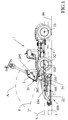
- said first arm 170 extends along a first axis S and comprises a first end portion 173 which is pivoted to said frame 3 by means of a third pivot 103.
- Said third pivot 103 identifies the front axis of rotation T of the first arm 170.
- Said first arm 170 integrally mounts a third arm 150 which in turn mounts a coupling point of a first pivot 101 which pivots said cutting deck 2.
- Said first pivot 101 of the lift apparatus 100 is integral with the cutting deck 2.
- Said third arm 150 is integrally mounted with the first arm 170 and is pivoted with the cutting deck 2 by means of the first pivot 101.
- Said first pivot 101 identifies a first axis of pivot R about which the cutting deck 2 rotates, which cutting deck is pivoted with the third arm 150, which is a prolongation of the first arm 170.
- the first arm 170 rotates about the front axis T, it raises the third arm 150 and it raises the first pivot 101, lifting in turn the cutting deck 2 from a lower position for cutting grass in which a lower base 24 of the cutting deck 2 faces ground 99 to a first position raised off ground 99.
- said lift apparatus 100 passes said cutting deck 2 from the lower position to the first position raised off ground 99.
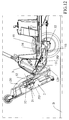
- Said lift apparatus 100 comprises a second arm 180 comprising a first end portion 185 pivoted with a fifth pivot 105 and a second end portion 184 which is slidably mounted with a link mechanism 4.
- Said fifth pivot 105 of the lift apparatus 100 is mounted on a point of the first arm 170. Said fifth pivot 105 is separated from said first pivot 101 by a distance D. Said distance D can be measured as the geometric projection on the first axis S.
- Two different pivots 101 and 105 spaced apart from each other advantageously allow the weight force of the cutting deck 2 to be better discharged during the lifting and when the cutting deck 2 is in at least one position raised off ground 99, thereby the arms 150, 170 and 180 are not to be very thick and heavy, thus conferring lightness to the lift apparatus 100.
- Said cutting deck 2 mounts the link mechanism 4 which is separated from said first pivot 101.
- Said link mechanism 4 is mounted integrally with the cutting deck 2.
- the link mechanism 4 is mounted with a rear portion 25 of the cutting deck 2 close to a lower base 24 of the cutting deck 2.
- Two different jointing points of the first pivot 101 and of the link mechanism 4 advantageously allow the weight force of the cutting deck 2 to be better discharged during the lifting and when the cutting deck 2 is in at least one position raised off ground 99, thereby the arms 150, 170 and 180 do not need to be very thick and heavy, thus conferring lightness to the lift apparatus 100.
- Said link mechanism 4 comprises a guide 40 which slidably mounts said second end portion 184 of the second arm 180 by means of a fourth pivot 104 of said second end portion 184 of the second arm 180.
- Said guide 40 of the link mechanism 4 is completely arranged for the whole length thereof along a longitudinal axis L which is parallel to a geometric plane B which outlines the lower base 24 of the cutting deck 2.
- Said guide 40 comprises two end stops: a second front end stop 41 and a first rear end stop 45 on the opposite side.
- Said first end stop 45 comprises a retainer notch 42 of such a size as to engage said fourth pivot 104 of said second end portion 184 of the second arm 180 of the lift apparatus 100.
- Said retainer notch 42 is hollowed out in guide 40 in the position of the first end stop 45.
- Said retainer notch 42 is advantageously hollowed out in the direction perpendicular to the longitudinal axis L to allow the fourth pivot 104 to be integrally snappingly engaged with said link mechanism 4 when the cutting deck 2 is in at least one position raised off ground 99. Indeed when said fourth pivot 104 is engaged with said at least one retainer notch 42, said fourth pivot 104 advantageously safely blocks said cutting deck 2 in said at least one position raised off ground 99.
- the fourth pivot 104 engages with the retainer notch 42 when the cutting deck 2 is in a second position raised off ground 99 for the maintenance of the cutting blades of the cutting deck 2.
- Said fifth pivot 105 is mounted with a second end portion 175 of said first arm 170. Said second end portion 175 of said first arm 170 is pivoted with said first end portion 185 of said second arm 180 by means of the fifth pivot 105. Said fifth pivot 105 identifies a fifth axis of rotation C, as shown in Figure 8 . The second arm 180 rotates about said fifth axis of rotation C when the cutting deck 2 is lifted.
- Said first arm 170 integrally mounts a third arm 150 of the lift apparatus 100 so that the third arm 150 always moves with said first arm 170.
- Said third arm 150 comprises a second portion 151 which extends by distance D in the same direction as the first arm 170 along the first axis S, and a first portion 155 which integrally links the third arm 150 with the first arm 170.
- Said second portion 151 of the third arm 150 is a prolongation of the first arm 170 along the first axis S.
- Said second portion 151 of the third arm 150 integrally mounts said first pivot 101 at distance D from the fifth pivot 105, as shown in particular in Figure 7 .
- Said distance D spans between a length of the first arm 170 and one quarter of the length of the first arm 170.
- Said distance D is advantageous for avoiding the cutting deck 2 from touching ground 99 while it rotates about the first axis of pivot R, in said at least one position raised off ground 99, in particular from the first position raised off ground 99 to the second position raised off ground 99 for the maintenance of the cutting blades of the cutting deck 2.
- Said second portion 151 of said third arm 150 is pivoted with said cutting deck 2 by means of the first pivot 101 and advantageously allows the cutting deck 2 to rotate about the first axis of pivot R.
- the first portion 155 of the third arm 150 is inclined by a third angle ⁇ with respect to the second portion 151 of the third arm 150.
- Said first portion 155 of the third arm 150 follows a third axis P.
- Said third angle ⁇ is from 0 to 90 sexagesimal degrees.
- the first portion 155 of the third arm 150 advantageously allows said first pivot 101 to be lifted by a distance U with respect to the first axis S which extends the first arm 170.
- Said second portion 151 of the third arm 150 always remains parallel to the first axis S.
- Said distance U is measured on a vertical axis W which is perpendicular to the first axis S, as shown in particular in Figure 7 .
- the inclination of the first portion 155 of the third arm 150 advantageously allows the cutting deck 2 to be rotated about the first axis of pivot R identified by the first pivot 101 without any portion of the cutting deck 2 touching ground 99.
- Said third arm 150 comprises an upper portion 153.
- a rod 130 connects the first lift apparatus 100 and the second lift apparatus 100 between one side and the other of the lawn mower 1, as shown in Figures 8 to 9 .
- Rod 130 is mounted integrally with said first arm (170).
- Rod 130 serves as an end stop for passing the cutting deck 2 from the lower position to the first position raised off ground 99.
- the upper end stop is identified by a front portion of frame 3.
- Said frame 3 comprises a lower portion 35 of the front portion of frame 3.
- Said lower portion 35 of frame 3 identifies a second axis F, said lower portion 35 of frame 3 along the second axis F is inclined by a second angle ⁇ with respect to ground 99, said second angle ⁇ is from 10 to 80 sexagesimal degrees.
- the first position raised off ground 99 of the cutting deck 2 is identified by the lifting of the cutting deck 2 which rotates about the front axis T of the second angle ⁇ up to rod 130 being in abutment with the lower portion 35 of frame 3.
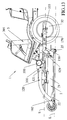
- Said cutting deck 2 integrally mounts a support arm 120 of said lift apparatus 100.
- Said support arm 120 comprises a front end portion 122 linked to the front portion 22 of the cutting deck 2 by means of a joint 102, a rear end portion 125 comprising a first portion 121 pivoted with said first pivot 101, and a second counterweight portion 129 at a rear end of said support arm 120.
- the second counterweight portion 129 is a prolongation of said support arm 120 toward the rear of the lawn mower 1.
- the first portion 121 of the rear end portion 125 of the support arm 120 is pivoted with said second portion 151 of the third arm 150 by means of the first pivot 101.
- the lift apparatus 100 passes the cutting deck 2 from the lower position for cutting grass, in which a lower base 24 of the cutting deck 2 faces ground 99 with the longitudinal axis L and the first axis S which are parallel to ground 99, up to a first position raised off ground 99 of said at least one position raised off ground 99, with the longitudinal axis L parallel to the first axis S and both the axes L, S raised off ground 99 by the second angle ⁇ .
- said upper portion 153 of said third arm 150 is in abutment with said counterweight portion 129 so that said counterweight portion 129 advantageously limits the rotational movement of the cutting deck 2 in downward anti-clockwise direction, thus avoiding the cutting deck 2 from falling back to the lower position of the cutting deck 2.
- Said counterweight portion 129 is advantageously an end stop for the cutting deck 2.
- Said rod 130 is in abutment with said lower portion 35 of frame 3 in said first position raised off ground 99.
- Said lower portion 35 of said frame 3 is advantageously a first end stop for the cutting deck 2.
- the lift apparatus 100 comprises a lift mechanism 300 which is mounted with said frame 3, inside frame 3.
- Said lift mechanism 300 comprises at least one pedal 305 mounted externally on frame 3 to be reached by a foot of a user, at least one cord 302 and at least one pulley 301 set in motion by said at least one pedal 305.
- Said at least one pulley 301 lifts said at least one cord 302 which is linked to said cutting deck 2.
- Cord 302 is linked to the cutting deck 2 in a position close to the first pivot 101.
- Said lift mechanism 300 lifts the cutting deck 2 from the lower position to the first position raised off ground 99.
- the lift mechanism 300 advantageously allows the weight of the cutting deck 2 to be carried, thus avoiding the weight of the cutting deck 2 to be discharged onto the pivots 101 and 105 alone, thus avoiding the jointing points from being fragile where there are pivots 101 and 105.
- the lift mechanism 300 advantageously allows the diameter of the arms 170, 180, 150 to be reduced, thus increasing the lightness of the lift apparatus 100 and increasing safety, thus avoiding the pivots 101 and 105 from breaking.
- the lift apparatus 100 allows said cutting deck 2 to be lifted up to a second position raised off ground 99 of said at least one position raised off ground 99.
- Said second position raised off ground 99 allows the maintenance of the cutting blades of the cutting deck 2 to be performed.
- Said second position raised off ground 99 for the maintenance of the cutting blades of the cutting deck 2 can be reached by manually lifting the front portion 22 of the cutting deck 2 upward, thus causing the cutting deck 2 to rotate about the first axis of pivot R identified by the first pivot 101.
- the fourth pivot 104 of the second arm 180 is engaged inside the retainer notch 42 to advantageously block the second position raised off ground 99 of the cutting deck 2 in a secure manner so that the user can safely perform the maintenance on cutting blades mounted under the cutting deck 2.
- a lower base 24 of the cutting deck 2 faces the front direction of the lawn mower 1 with the longitudinal axis L inclined by a first angle ⁇ with respect to the first axis S, said first angle ⁇ is from 0 to 90 sexagesimal degrees.
- the first portion 121 of the rear end portion 125 of the support arm 120 is not in front of the center of mass 21 of the cutting deck 2 in order to ensure that the cutting deck 2 may rotate freely on the first pivot 101 about the first axis of pivot R without touching ground 99 in the first position raised off ground 99 of the cutting deck 2.
- the first portion 121 is positioned in the rear end portion 125 of the support arm 120 and the counterweight portion 129 advantageously allows a counterweight to be obtained to the weight of the cutting deck 2 when it is in the second position raised off ground 99 for the maintenance of the cutting blades of the cutting deck 2.
- a further advantage is given by the fact that the first pivot 101 is positioned so that the distance between the drive pulley 53 and the driven pulley 52 does not increase with the rotation, thus allowing the second position raised off ground 99 of the cutting deck 2 to be reached without disassembling and without detaching the driving belt 51 from its seat on the two pulleys 52 and 53.
- the front end portion 122 advantageously allows the weight of the cutting deck 2 to be discharged onto the first pivot 101.
- another part of the weight of the cutting deck 2 is advantageously discharged from the second arm 180 onto the fifth pivot 105.
- Said other part of the weight of the cutting deck 2 is discharged even better onto the fifth pivot 105 without breaking it, which is advantageously due to the fact that said first portion 185 of said second arm 180 of the lift apparatus 100 is inclined by a fourth angle ⁇ with respect to a fifth axis of rotation C identified by said fifth pivot 105.
- Said first portion 185 of said second arm 180 follows an axis of bending G.
- said fourth angle ⁇ is from 10 to 80 sexagesimal degrees, thus advantageously allowing safer discharging of the weight of the cutting deck 2 without breaking the lift apparatus 100.
- the center of mass 21 of the cutting deck 2 being arranged in an advanced position toward the front of the lawn mower 1 and the center of mass 21 being not positioned in front of the first pivot 101 also allow a further technical advantage to be achieved due to the fact that the front end portion 122 pushes the cutting deck 2 downward to the lower position, thus avoiding the risk of the cutting deck 2 overturning, making the work of the user dangerous.
- the lift apparatus 100 according to the present invention advantageously allows the lawn mower 1 to be operated more safely when the grass is cut as compared to the lift apparatuses of the prior art.
- the position of the first pivot 101 with respect to the position of the center of mass 21 of the cutting deck 2 promotes the lifting of the cutting deck 2 from the lower position to any one of the positions raised off ground 99, without there being a need to disassemble or detach a driving belt 51 between a drive pulley 53 which is rotatably mounted with frame 3 and a driven pulley 52 which is rotatably mounted with the cutting deck 2.
- Said drive pulley 53 is mounted integrally with another drive pulley 54 which is at a greater height from ground 99 with respect to the drive pulley 53.
- Said other drive pulley 54 is coupled to another driving belt 55, which is in turn coupled to a pulley of a motor (not shown in the figures).
- the position of the first pivot 101 with respect to the position of the center of mass 21 of the cutting deck 2 allows a distance PD between the drive pulley 53 and the driven pulley 52 to remain constant when the cutting deck 2 passes from the lower position to any one of the positions raised off ground 99, i.e. during the rotation of the cutting deck 2 about the first axis of pivot R of the first pivot 101, without disassembling and without detaching the driving belt 51 from the seat thereof on the two pulleys 52 and 53.
- Distance PD between the drive pulley 53 and the driven pulley 52 is measured along the driving belt 51, as shown in Figures 10 to 12 , 18 .
- the lift apparatus 100 passes the cutting deck 2 in sequence from the lower position to the first position raised off ground 99 up to the second position raised off ground 99 for the maintenance of the cutting blades of the cutting deck 2.
- the first axis S along the first arm 170 and the longitudinal axis L along guide 40 are parallel to ground 99 in the lower position of the cutting deck 2.
- mechanism 300 lifts cord 302, thus causing the first arm 170 to be raised.
- the first arm 170 rotates about the front axis T of the third pivot 103, thus lifting the third arm 150 and the first pivot 101 together.
- the first arm 170 lifts the cutting deck 2 from the lower position to the first position raised off the ground in which rod 130 abuts with the lower portion 35 of frame 3.
- the second arm 180 rotates about the fifth axis C of the fifth pivot 105, while the fourth pivot 104 remains close to the second end stop 41 and does not slide inside guide 40 of the link mechanism 4.
- the first arm 170 cannot be lifted.
- the user may advantageously lift the cutting deck 2 from the lower position to the first position raised off ground 99 without removing his/her hands from a steering wheel of the lawn mower 1, rather by simply using pedal 305 with a foot.
- Said first position raised off ground 99 of the cutting deck 2 is advantageously useful for when the lawn mower 1 is moved from storage to a place where cutting of the grass should occur, so that the cutting blades are not damaged and the lower base 24 of the cutting deck 2 is not damaged either.
- the cutting deck 2 may be lifted manually by taking it from the front portion 22 and lifting it upward and causing said cutting deck 2 to rotate about the first axis of pivot R of the first pivot 101.
- the second counterweight portion 129 of the rear end portion 125 of the support arm 120 rotates about the first axis of pivot R to counterbalance the weight of the cutting deck 2 in the second position raised off ground 99 and to advantageously keep the cutting deck 99 stopped in a position of unstable balance when it is in the position raised off ground 99.
- the second arm 180 no longer rotates about the fifth axis C of the fifth pivot 105, but the fourth pivot 104 slides inside guide 40 of the link mechanism 4 up to reaching the first end stop 45.
- the fourth pivot 104 can also be engaged with the retainer notch 42 of guide 40 so as to cause the cutting deck 2 to remain safely blocked in the second position raised off ground 99 without the risk of the cutting deck 2 returning to the first position raised off ground 99.
- the second counterweight portion 129 of the support arm 120 indeed advantageously allows the cutting deck 2 to be positioned stopped in the second position raised off ground 99 without the cutting deck 2 moving from this position of unstable balance and thus allowing the user not to make an effort when holding the cutting deck 2 stopped in the second position raised off ground 99.
- a single user alone may advantageously remove his/her hands from the cutting deck 2 and the fourth pivot 104 automatically engages in the retainer notch 42 to safely maintain the second position raised off ground 99 of the cutting deck 2. At this point, operations may be safely performed on the front of the lawn mower 1 for the maintenance of the cutting blades of the cutting deck 2.
- first arm 170 and the third arm 150 are a single piece and the third arm 150 is a prolongation of the first arm 170 along the first axis S.
- first pivot 101 in mounted with the first arm 170 and pivots said cutting deck 2.
- the first pivot 101 and the fifth pivot 105 are mounted on the first arm 170 and are separated by distance D measured along axis S.
- said guide 40 of said link mechanism 4 is in the form of an arc of circumference and at least one portion of the arc of circumference is arranged along the longitudinal axis L so as to facilitate the sliding of the fourth pivot 104 along guide 40 when the cutting deck 2 passes from the lower position to the raised positions.
- Two end portions of said at least one portion of the arc of circumference are arranged to intersect the longitudinal axis L.
- the first arm 170 may be one arm alone, and it may be mounted on one side of the lawn mower 1.
- said guide 40 can comprise a multiplicity of retainer notches 42 of such a size as to engage said fourth pivot 104 of said second end portion 184 of said second arm 180 of the lift apparatus 100.
- Each of said multiplicity of retainer notches 42 advantageously safely blocks a single position raised off ground 99 of the cutting deck 2 of the multiplicity of positions raised off ground 99 of the cutting deck 2.
- the cutting deck 2 can be mounted behind frame 3.
- the link mechanism 4 is in one piece with the cutting deck 2.
- the upper portion 153 can be in one piece with the first arm 170.
- more than one pulley 301 are included.
- the first pivot 101 is positioned so that distance PD between the drive pulley 53 and the driven pulley 52 varies its length between 0% and 3% with the rotation, thus allowing the second position raised off ground 99 of the cutting deck 2 to be reached without disassembling and without detaching the driving belt 51 from its seat on the two pulleys 52 and 53.
- the position of the first pivot 101 with respect to the position of the center of mass 21 of the cutting deck 2 allows distance PD between the drive pulley 53 and the driven pulley 52 to vary its length between 0% and 0.5% when the cutting deck 2 passes from the lower position to the first position raised off ground 99.
- the position of the first pivot 101 with respect to the position of the center of mass 21 of the cutting deck 2 allows distance PD between the drive pulley 53 and the driven pulley 52 to vary its length between 0.5% and 3% when the cutting deck 2 passes from the first position raised off ground 99 to the second position raised off ground 99, i.e. during the rotation of the cutting deck 2 about the first axis of pivot R of the first pivot 101, without disassembling and without detaching the driving belt 51 from the seat thereof on the two pulleys 52 and 53.
- distance PD between the drive pulley 53 and the driven pulley 52 is 546 mm when the cutting deck 2 is in the lower position.
- Distance PD becomes 544 mm when the cutting deck 2 is in the first position raised off ground 99, thus varying its length by 0.4%.
- Distance PD becomes 560 mm when the cutting deck 2 is in the second position raised off ground 99, thus varying its length by 2.5%.
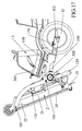
- FIG. 13 to 18 An alternative again is shown in Figures 13 to 18 , where an alternative lawn mower 1 is shown comprising an alternative lift apparatus 100 comprising said first arm 170 which comprises said prolongation 150, but without the second arm 180, without the link mechanism 4, without the fourth pivot 105.
- Said prolongation 150 of the first arm 170 of the alternative lift apparatus 100 integrally mounts a third arm 150 of the lift apparatus 100.
- Said third arm 150 comprises said second portion 151 which extends by distance D in the same direction as the first arm 170 along the first axis S, and the first portion 155 which integrally links the third arm 150 with the first arm 170, said second portion 151 of the third arm 150 integrally mounts said first pivot 101, said second portion 151 of said third arm 150 is pivoted with said cutting deck 2.
- Said second portion 151 of the third arm 150 is parallel to the first axis S and is inclined by the third angle ⁇ with respect to the first portion 155, said third angle ⁇ is from 0 to 90 sexagesimal degrees.
- the cutting deck 2 of the lawn mower 1 mounts at least one support arm 120 of the lift apparatus 100, said at least one support arm 120 comprises a front end portion 122 linked to the front portion 22 of the cutting deck 2 by means of a joint 102, a rear end portion 125 comprising a second portion 121 pivoted with said first pivot 101 and a first counterweight portion 129 at a rear end of said at least one support arm 120.
- the second portion 121 mounts a safety handle 500 which automatically engages by means of a recall spring, engaging integrally the first arm 170 with the support arm 120 in the lower position of the cutting deck 2 so as to keep fixed the lower position of the cutting deck 2.
- the handle 500 blocks prolongation 150 of the first arm 170 by passing through a bond 550 with the support arm 120.
- handle 500 is left blocked so that the first arm 170 remains integral with the support arm 120 while the cutting deck 2 rotates about the third pivot 103.
- Bond 550 is a hole made on the first arm 170 or on prolongation 150 thereof.
- FIG. 19 A further alternative is shown in Figures 19 to 24 and includes a block lever 600 provided in place of the safety handle 500.
- the support arm 120 mounts a block lever 600 which engages a block pin 630 passing through a bond 550 of the first arm 170, thus making the first arm 170 integral with the support arm 120 in the lower position of the cutting deck 2 and keeping fixed the lower position of the cutting deck 2.
- the support arm 120 comprises a fulcrum 601 which pivots said block lever 600. Said fulcrum 601 is an outward prolongation which allows said block lever 600 to tilt.
- Said block lever 600 comprises an end portion 603 which mounts a pivot 630 which engages in bond 550 which is a hole made on the first arm 170 or on prolongation 150, thus making the first arm 170 integral with the support arm 120 in the lower position of the cutting deck 2 so as to keep fixed the lower position of the cutting deck 2.
- Pivot 630 of the block lever 600 blocks prolongation 150 of the first arm 170 by passing through bond 550 with the support arm 120.
- pivot 630 of the block lever 600 is left blocked so that the first arm 170 remains integral with the support arm 120 while the cutting deck 2 rotates about the third pivot 103.
- a further alternative may be provided, as shown in Figures 17 , 19 to 24 , where prolongation 150 of the first arm 170 comprises a further bond 560.
- Said further bond 560 fixes handle 500 or the block lever 600 when the cutting deck 2 is in the second position raised off ground 99 for the maintenance of the cutting blades of the cutting deck 2.
- the first arm 170 can comprise said further bond 560.
- handle 500 blocks the support arm 120 with the first arm 170.
- the first arm 170 can also comprise said further bond 560 and when said cutting deck 2 is in the second position raised off ground 99 for the maintenance of the cutting blades of the cutting deck 2, the block lever 600 passes said block pin 630 of the block lever 600 through said further bond 560. Said block pin 630 of the block lever 600 blocks the support arm 120 with the first arm 170.
- said further bond 560 is in the shape of a hook, but it could also be a through hole.
- handle 500 may be fixed with said further bond 560.
- the block lever 600 may be fixed with said further bond 560, thus causing pivot 630 of the block lever to penetrate in contrast with the further bound 560.
- belt 51 may be kept taught by a tensioner 501 of the lawn mower 1.
- Said tensioner 501 is a pulley mounted integrally with frame 3, as shown for example in Figure 18 .
- the lift apparatus 100 of the cutting deck 2 of the lawn mower 1 is safe, easy to be constructed, is not complex and lasts longer over time without breaking, thus allowing the positions raised off ground 99 of the cutting deck 2 to be safely kept over time.
- the lift apparatus 100 is very lightweight, indeed all the arms thereof 170, 180, 120, 150 are thin and lightweight since the weight load forces of the cutting deck 2 are not discharged onto particularly fragile points of pivot 101, 105 alone, but they are absorbed by the geometry of the lift apparatus 100 itself.
Abstract
Description
- The present invention relates to a lift apparatus for a cutting deck of a lawn mower.
- In the prior art,
EP-1759569-A1 describes a lawn mower comprising a frame, a cutting deck and at least one lift apparatus arranged on one side of the lawn mower and which links the cutting deck with the frame. Said lift apparatus comprises a first arm, said first arm comprises a first end portion which is pivoted to said frame by means of a third pivot. Said first arm is integral with a first pivot which pivots said cutting deck. Said first pivot of the lift apparatus is integral with the cutting deck. Said lift apparatus passes said cutting deck from a lower position for cutting grass to at least one position raised off the ground. Said first arm comprises a prolongation. Said prolongation of the first arm integrally mounts a third arm of the lift apparatus. Said third arm comprises a second portion which extends over a distance in the same direction as the first arm along the first axis, and a first portion which integrally links the third arm with the first arm. Said second portion of the third arm integrally mounts said first pivot, said second portion of said third arm is pivoted with said cutting deck. Said second portion of the third arm is parallel to the first axis. Said frame comprises a lower portion which identifies a second axis, said lower portion of the frame along the second axis is inclined by a second angle with respect to the ground. Said cutting deck comprises a front portion, a rear portion and a center of mass between the front portion and the rear portion, said cutting deck mounts at least one support arm of the lift apparatus, said at least one support arm comprises a front end portion linked to the front portion of the cutting deck by means of a joint, a rear end portion comprising a second portion pivoted with said first pivot. Said lift apparatus is adapted to pass the cutting deck from the lower position for cutting grass, in which a lower base of the cutting deck faces the ground with a longitudinal axis and the first axis which are parallel to the ground, to a first position raised off the ground of said at least one position raised off the ground, with the longitudinal axis parallel to the first axis and both axes raised off the ground by the second angle, up to a second position raised off the ground of said at least one position raised off the ground, a lower base of the cutting deck faces the front direction of the lawn mower in said position raised off the ground, with the longitudinal axis inclined by a first angle with respect to the first axis. The longitudinal axis is parallel to a geometric plane which outlines the lower base of the cutting deck. Said cutting deck is mounted in front of the frame. The lawn mower comprises two lift apparatuses with two first arms which are pivoted, by means of two third pivots, to a front axis of two front wheels which are rotatably mounted with the frame. The lift apparatus comprises a safety device which is adapted to be engaged with the lift arm in order to keep the cutting deck stopped when the cutting deck passes from the operating position to the first position raised off the ground. In order to pass the cutting deck from the first position raised off the ground to the second position raised off the ground, there is a need to release the safety device to release the lift arm from the cutting deck. -
US-2005/016143-A1 describes a lift apparatus for a cutting deck of a lawn mower in which there is a need to disassemble a linking belt between a drive pulley and a driven pulley when the cutting deck is raised off the ground. -
EP-0213096-A1 describes a lawn mower comprising a steering device which keeps a driving belt connected between two pulleys and does not provide for the cutting deck to be raised off the ground for the maintenance of the blades. -
US-5029437-A describes a lawn mower comprising a lift apparatus for the cutting deck for cutting the grass at a different height and for avoiding obstacles, and it does not provide for the cutting deck to be raised off the ground for the maintenance of the blades. -
US-4914898-A describes a lift apparatus for a cutting deck in which there is a need to disassemble a linking belt between the pulleys when the deck is raised by an angle greater than 9° off the ground, whereby it may not be possible to cause the cutting deck to be raised off the ground enough for the maintenance of the blades. - Before passing the cutting deck from the lower position to any one of the positions raised off ground, there disadvantageously is a need to detach the belt from a drive pulley or from a driven pulley, otherwise the belt does not allow the raising, since the belt is not extendible.
- It is the object of the present invention to make a lift apparatus for a cutting deck of a lawn mower which is safe, easy to construct, is not complex, lasts more over time, which allows a raised position of the cutting deck to be kept safely over time, which lift apparatus may be lightweight, which loading forces of the cutting deck are not discharged onto particularly fragile points of the pivot, which driving belts do not require detaching between a motor and pulleys of the cutting deck when the cutting deck of the lawn mower is raised completely off the ground for the maintenance of the cutting blades of the cutting deck.
- In accordance with the invention, such an object is achieved by a lawn mower according to claim 1.
- These and other features of the present invention will become more apparent from the following detailed description of a practical embodiment thereof, shown by way of non-limitative example in the accompanying drawings, in which:
-
Figure 1 shows a side plan view of a lawn mower comprising a lift apparatus for a cutting deck in a lower position for cutting grass; -
Figure 2 shows an enlargement A ofFigure 1 , with the cutting deck of the lawn mower in the lower position; -
Figure 3 shows the enlargement A with the cutting deck of the lawn mower in a first position raised off the ground; -
Figure 4 shows the enlargement A with the cutting deck of the lawn mower in a second position raised off the ground for the maintenance of the blades of the cutting deck; -
Figure 5 shows a front view of the lawn mower comprising the cutting deck in the first raised position; -
Figure 6 shows a sectional view according to line VI-Vi inFigure 5 , in which there is shown a portion of a frame of the lawn mower comprising a mechanism for lifting the cutting deck from a lower position to a raised position; -
Figure 7 shows a side view of the lift apparatus; -
Figure 8 shows a top view of the lift apparatus; -
Figure 9 shows a top plan view of the lift apparatus mounted with the cutting deck of the lawn mower; -
Figure 10 shows an enlargement B of a sectional view according to line X-X inFigure 5 , of a belt and pulleys with the cutting deck of the lawn mower in the lower position; -
Figure 11 shows the enlargement B of the sectional view according to line X-X inFigure 5 , of the belt and the pulleys with the cutting deck of the lawn mower in the first position raised off the ground; -
Figure 12 shows the enlargement B of the sectional view according to line X-X inFigure 5 , of the belt and the pulleys with the cutting deck of the lawn mower in the second position raised off the ground; -
Figure 13 shows a side plan view of a front portion of an alternative lawn mower comprising an alternative cutting deck in a lower position; -
Figure 14 shows a top plan view of the lawn mower inFigure 13 ; -
Figure 15 shows a sectional view according to the line XV-XV inFigure 14 ; -
Figure 16 shows a side plan view of the lawn mower inFigure 13 , with the cutting deck of the lawn mower in a first position raised off the ground; -
Figure 17 shows a side plan view of the lawn mower inFigure 13 , with the cutting deck of the lawn mower in a second position raised off the ground for the maintenance of the cutting blades of the cutting deck; -
Figure 18 shows a sectional view according to line XVIII-XVIII inFigure 14 ; -
Figure 19 shows a side plan view of a lawn mower comprising a lift apparatus for a cutting deck in a lower position for cutting grass, comprising a further bond of the first arm for fixing the second position raised off the ground; -
Figure 20 shows the lawn mower inFigure 19 with the cutting deck of the lawn mower in the second position raised off the ground for the maintenance of the blades of the cutting deck; -
Figure 21 shows a side view of a detail of the support arm and of the first arm with a block lever comprising a block pin in a blocked position between the first arm and the support arm; -
Figure 22 shows a sectional view according to line XXII-XXII inFigure 21 ; -
Figure 23 shows the side view inFigure 21 , with the block pin in a released position to contain the mutual movement of the support arm with respect to the first arm; -
Figure 24 shows a sectional view according to line XXXIV-XXXIV inFigure 23 . - With reference to the drawings listed above and in particular to
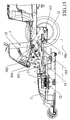
Figure 1 , a lawn mower 1 is denoted comprising aframe 3, acutting deck 2 and twolift apparatuses 100, one for each side of the lawn mower 1. Saidlift apparatus 100 links thecutting deck 2 with theframe 3. - Said
cutting deck 2 is mounted in front offrame 3. Saidcutting deck 2 comprises afront portion 22, arear portion 25 and a center ofmass 21 between thefront portion 22 and therear portion 25. - As shown in particular in
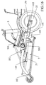
Figures 2 to 4 ,7 to 8 , twolift apparatuses 100 each comprise afirst arm 170. The twofirst arms 170 are pivoted, by means of twothird pivots 103, to a front axis T of twofront wheels 32 which are rotatably mounted withframe 3. Two otherrear wheels 33 are rotatably mounted with a rear portion offrame 3. - As shown in particular in
Figures 2 to 4 ,7 to 8 , saidfirst arm 170 extends along a first axis S and comprises afirst end portion 173 which is pivoted to saidframe 3 by means of athird pivot 103. Saidthird pivot 103 identifies the front axis of rotation T of thefirst arm 170. Saidfirst arm 170 integrally mounts athird arm 150 which in turn mounts a coupling point of afirst pivot 101 which pivots said cuttingdeck 2. - Said
first pivot 101 of thelift apparatus 100 is integral with thecutting deck 2. Saidthird arm 150 is integrally mounted with thefirst arm 170 and is pivoted with thecutting deck 2 by means of thefirst pivot 101. Saidfirst pivot 101 identifies a first axis of pivot R about which thecutting deck 2 rotates, which cutting deck is pivoted with thethird arm 150, which is a prolongation of thefirst arm 170. When thefirst arm 170 rotates about the front axis T, it raises thethird arm 150 and it raises thefirst pivot 101, lifting in turn thecutting deck 2 from a lower position for cutting grass in which alower base 24 of thecutting deck 2 facesground 99 to a first position raised offground 99. Thereby, saidlift apparatus 100 passes said cuttingdeck 2 from the lower position to the first position raised offground 99. - Said
lift apparatus 100 comprises asecond arm 180 comprising afirst end portion 185 pivoted with afifth pivot 105 and asecond end portion 184 which is slidably mounted with alink mechanism 4. - Said
fifth pivot 105 of thelift apparatus 100 is mounted on a point of thefirst arm 170. Saidfifth pivot 105 is separated from saidfirst pivot 101 by a distance D. Said distance D can be measured as the geometric projection on the first axis S. Twodifferent pivots deck 2 to be better discharged during the lifting and when the cuttingdeck 2 is in at least one position raised offground 99, thereby thearms lift apparatus 100. - Said cutting
deck 2 mounts thelink mechanism 4 which is separated from saidfirst pivot 101. Saidlink mechanism 4 is mounted integrally with the cuttingdeck 2. Thelink mechanism 4 is mounted with arear portion 25 of the cuttingdeck 2 close to alower base 24 of the cuttingdeck 2. Two different jointing points of thefirst pivot 101 and of thelink mechanism 4 advantageously allow the weight force of the cuttingdeck 2 to be better discharged during the lifting and when the cuttingdeck 2 is in at least one position raised offground 99, thereby thearms lift apparatus 100. - Said
link mechanism 4 comprises aguide 40 which slidably mounts saidsecond end portion 184 of thesecond arm 180 by means of afourth pivot 104 of saidsecond end portion 184 of thesecond arm 180. - Said
guide 40 of thelink mechanism 4 is completely arranged for the whole length thereof along a longitudinal axis L which is parallel to a geometric plane B which outlines thelower base 24 of the cuttingdeck 2. Saidguide 40 comprises two end stops: a secondfront end stop 41 and a first rear end stop 45 on the opposite side. Saidfirst end stop 45 comprises aretainer notch 42 of such a size as to engage saidfourth pivot 104 of saidsecond end portion 184 of thesecond arm 180 of thelift apparatus 100. Saidretainer notch 42 is hollowed out inguide 40 in the position of thefirst end stop 45. Saidretainer notch 42 is advantageously hollowed out in the direction perpendicular to the longitudinal axis L to allow thefourth pivot 104 to be integrally snappingly engaged with saidlink mechanism 4 when the cuttingdeck 2 is in at least one position raised offground 99. Indeed when saidfourth pivot 104 is engaged with said at least oneretainer notch 42, saidfourth pivot 104 advantageously safely blocks said cuttingdeck 2 in said at least one position raised offground 99. Thefourth pivot 104 engages with theretainer notch 42 when the cuttingdeck 2 is in a second position raised offground 99 for the maintenance of the cutting blades of the cuttingdeck 2. - Said
fifth pivot 105 is mounted with asecond end portion 175 of saidfirst arm 170. Saidsecond end portion 175 of saidfirst arm 170 is pivoted with saidfirst end portion 185 of saidsecond arm 180 by means of thefifth pivot 105. Saidfifth pivot 105 identifies a fifth axis of rotation C, as shown inFigure 8 . Thesecond arm 180 rotates about said fifth axis of rotation C when the cuttingdeck 2 is lifted. - Said
first arm 170 integrally mounts athird arm 150 of thelift apparatus 100 so that thethird arm 150 always moves with saidfirst arm 170. - Said
third arm 150 comprises asecond portion 151 which extends by distance D in the same direction as thefirst arm 170 along the first axis S, and afirst portion 155 which integrally links thethird arm 150 with thefirst arm 170. Saidsecond portion 151 of thethird arm 150 is a prolongation of thefirst arm 170 along the first axis S. Saidsecond portion 151 of thethird arm 150 integrally mounts saidfirst pivot 101 at distance D from thefifth pivot 105, as shown in particular inFigure 7 . Said distance D spans between a length of thefirst arm 170 and one quarter of the length of thefirst arm 170. Said distance D is advantageous for avoiding the cuttingdeck 2 from touchingground 99 while it rotates about the first axis of pivot R, in said at least one position raised offground 99, in particular from the first position raised offground 99 to the second position raised offground 99 for the maintenance of the cutting blades of the cuttingdeck 2. - Said
second portion 151 of saidthird arm 150 is pivoted with said cuttingdeck 2 by means of thefirst pivot 101 and advantageously allows the cuttingdeck 2 to rotate about the first axis of pivot R. - The
first portion 155 of thethird arm 150 is inclined by a third angle γ with respect to thesecond portion 151 of thethird arm 150. Saidfirst portion 155 of thethird arm 150 follows a third axis P. Said third angle γ is from 0 to 90 sexagesimal degrees. Thefirst portion 155 of thethird arm 150 advantageously allows saidfirst pivot 101 to be lifted by a distance U with respect to the first axis S which extends thefirst arm 170. Saidsecond portion 151 of thethird arm 150 always remains parallel to the first axis S. Said distance U is measured on a vertical axis W which is perpendicular to the first axis S, as shown in particular inFigure 7 . - The inclination of the
first portion 155 of thethird arm 150 advantageously allows the cuttingdeck 2 to be rotated about the first axis of pivot R identified by thefirst pivot 101 without any portion of the cuttingdeck 2 touchingground 99. - Said
third arm 150 comprises anupper portion 153. - A
rod 130 connects thefirst lift apparatus 100 and thesecond lift apparatus 100 between one side and the other of the lawn mower 1, as shown inFigures 8 to 9 . -
Rod 130 is mounted integrally with said first arm (170). -
Rod 130 serves as an end stop for passing the cuttingdeck 2 from the lower position to the first position raised offground 99. The upper end stop is identified by a front portion offrame 3. - Said
frame 3 comprises alower portion 35 of the front portion offrame 3. Saidlower portion 35 offrame 3 identifies a second axis F, saidlower portion 35 offrame 3 along the second axis F is inclined by a second angle β with respect toground 99, said second angle β is from 10 to 80 sexagesimal degrees. The first position raised offground 99 of the cuttingdeck 2 is identified by the lifting of the cuttingdeck 2 which rotates about the front axis T of the second angle β up torod 130 being in abutment with thelower portion 35 offrame 3. - Said cutting
deck 2 integrally mounts asupport arm 120 of saidlift apparatus 100. - Said
support arm 120 comprises afront end portion 122 linked to thefront portion 22 of the cuttingdeck 2 by means of a joint 102, arear end portion 125 comprising afirst portion 121 pivoted with saidfirst pivot 101, and asecond counterweight portion 129 at a rear end of saidsupport arm 120. Thesecond counterweight portion 129 is a prolongation of saidsupport arm 120 toward the rear of the lawn mower 1. Thefirst portion 121 of therear end portion 125 of thesupport arm 120 is pivoted with saidsecond portion 151 of thethird arm 150 by means of thefirst pivot 101. - The
lift apparatus 100 passes the cuttingdeck 2 from the lower position for cutting grass, in which alower base 24 of the cuttingdeck 2 facesground 99 with the longitudinal axis L and the first axis S which are parallel to ground 99, up to a first position raised offground 99 of said at least one position raised offground 99, with the longitudinal axis L parallel to the first axis S and both the axes L, S raised offground 99 by the second angle β. - In said first position raised off
ground 99, saidupper portion 153 of saidthird arm 150 is in abutment with saidcounterweight portion 129 so that saidcounterweight portion 129 advantageously limits the rotational movement of the cuttingdeck 2 in downward anti-clockwise direction, thus avoiding the cuttingdeck 2 from falling back to the lower position of the cuttingdeck 2. Saidcounterweight portion 129 is advantageously an end stop for the cuttingdeck 2. - Said
rod 130 is in abutment with saidlower portion 35 offrame 3 in said first position raised offground 99. Saidlower portion 35 of saidframe 3 is advantageously a first end stop for the cuttingdeck 2. - As shown in particular in
Figures 5 to 6 , thelift apparatus 100 comprises alift mechanism 300 which is mounted with saidframe 3, insideframe 3. Saidlift mechanism 300 comprises at least onepedal 305 mounted externally onframe 3 to be reached by a foot of a user, at least onecord 302 and at least onepulley 301 set in motion by said at least onepedal 305. Said at least onepulley 301 lifts said at least onecord 302 which is linked to said cuttingdeck 2.Cord 302 is linked to the cuttingdeck 2 in a position close to thefirst pivot 101. Saidlift mechanism 300 lifts thecutting deck 2 from the lower position to the first position raised offground 99. Thelift mechanism 300 advantageously allows the weight of the cuttingdeck 2 to be carried, thus avoiding the weight of the cuttingdeck 2 to be discharged onto thepivots pivots lift mechanism 300 advantageously allows the diameter of thearms lift apparatus 100 and increasing safety, thus avoiding thepivots - The
lift apparatus 100 allows said cuttingdeck 2 to be lifted up to a second position raised offground 99 of said at least one position raised offground 99. Said second position raised offground 99 allows the maintenance of the cutting blades of the cuttingdeck 2 to be performed. Said second position raised offground 99 for the maintenance of the cutting blades of the cuttingdeck 2 can be reached by manually lifting thefront portion 22 of the cuttingdeck 2 upward, thus causing the cuttingdeck 2 to rotate about the first axis of pivot R identified by thefirst pivot 101. Once it has reached the end stop ofguide 40, thefourth pivot 104 of thesecond arm 180 is engaged inside theretainer notch 42 to advantageously block the second position raised offground 99 of the cuttingdeck 2 in a secure manner so that the user can safely perform the maintenance on cutting blades mounted under the cuttingdeck 2. Indeed, in said second position raised offground 99, alower base 24 of the cuttingdeck 2 faces the front direction of the lawn mower 1 with the longitudinal axis L inclined by a first angle α with respect to the first axis S, said first angle α is from 0 to 90 sexagesimal degrees. - Advantageously, the
first portion 121 of therear end portion 125 of thesupport arm 120 is not in front of the center ofmass 21 of the cuttingdeck 2 in order to ensure that the cuttingdeck 2 may rotate freely on thefirst pivot 101 about the first axis of pivot R without touchingground 99 in the first position raised offground 99 of the cuttingdeck 2. Thefirst portion 121 is positioned in therear end portion 125 of thesupport arm 120 and thecounterweight portion 129 advantageously allows a counterweight to be obtained to the weight of the cuttingdeck 2 when it is in the second position raised offground 99 for the maintenance of the cutting blades of the cuttingdeck 2. - A further advantage is given by the fact that the
first pivot 101 is positioned so that the distance between thedrive pulley 53 and the drivenpulley 52 does not increase with the rotation, thus allowing the second position raised offground 99 of the cuttingdeck 2 to be reached without disassembling and without detaching the drivingbelt 51 from its seat on the twopulleys - When the cutting
deck 2 is in the second position raised offground 99, thefront end portion 122 advantageously allows the weight of the cuttingdeck 2 to be discharged onto thefirst pivot 101. Moreover, another part of the weight of the cuttingdeck 2 is advantageously discharged from thesecond arm 180 onto thefifth pivot 105. Said other part of the weight of the cuttingdeck 2 is discharged even better onto thefifth pivot 105 without breaking it, which is advantageously due to the fact that saidfirst portion 185 of saidsecond arm 180 of thelift apparatus 100 is inclined by a fourth angle δ with respect to a fifth axis of rotation C identified by saidfifth pivot 105. Saidfirst portion 185 of saidsecond arm 180 follows an axis of bending G. As shown inFigure 8 , said fourth angle δ is from 10 to 80 sexagesimal degrees, thus advantageously allowing safer discharging of the weight of the cuttingdeck 2 without breaking thelift apparatus 100. - The center of
mass 21 of the cuttingdeck 2 being arranged in an advanced position toward the front of the lawn mower 1 and the center ofmass 21 being not positioned in front of thefirst pivot 101 also allow a further technical advantage to be achieved due to the fact that thefront end portion 122 pushes the cuttingdeck 2 downward to the lower position, thus avoiding the risk of the cuttingdeck 2 overturning, making the work of the user dangerous. Thereby, thelift apparatus 100 according to the present invention advantageously allows the lawn mower 1 to be operated more safely when the grass is cut as compared to the lift apparatuses of the prior art. - As is shown in
Figures 10 to 12 , the position of thefirst pivot 101 with respect to the position of the center ofmass 21 of the cuttingdeck 2 promotes the lifting of the cuttingdeck 2 from the lower position to any one of the positions raised offground 99, without there being a need to disassemble or detach a drivingbelt 51 between adrive pulley 53 which is rotatably mounted withframe 3 and a drivenpulley 52 which is rotatably mounted with the cuttingdeck 2. - Said drive
pulley 53 is mounted integrally with anotherdrive pulley 54 which is at a greater height fromground 99 with respect to the drivepulley 53. Saidother drive pulley 54 is coupled to another drivingbelt 55, which is in turn coupled to a pulley of a motor (not shown in the figures). - The position of the
first pivot 101 with respect to the position of the center ofmass 21 of the cuttingdeck 2 allows a distance PD between thedrive pulley 53 and the drivenpulley 52 to remain constant when the cuttingdeck 2 passes from the lower position to any one of the positions raised offground 99, i.e. during the rotation of the cuttingdeck 2 about the first axis of pivot R of thefirst pivot 101, without disassembling and without detaching the drivingbelt 51 from the seat thereof on the twopulleys drive pulley 53 and the drivenpulley 52 is measured along the drivingbelt 51, as shown inFigures 10 to 12 ,18 . - With regard to operation, the
lift apparatus 100 passes the cuttingdeck 2 in sequence from the lower position to the first position raised offground 99 up to the second position raised offground 99 for the maintenance of the cutting blades of the cuttingdeck 2. - As shown in
Figures 1 to 2 , the first axis S along thefirst arm 170 and the longitudinal axis L alongguide 40 are parallel to ground 99 in the lower position of the cuttingdeck 2. - As shown in particular in
Figure 3 ,mechanism 300lifts cord 302, thus causing thefirst arm 170 to be raised. Thefirst arm 170 rotates about the front axis T of thethird pivot 103, thus lifting thethird arm 150 and thefirst pivot 101 together. Thefirst arm 170 lifts thecutting deck 2 from the lower position to the first position raised off the ground in whichrod 130 abuts with thelower portion 35 offrame 3. Thesecond arm 180 rotates about the fifth axis C of thefifth pivot 105, while thefourth pivot 104 remains close to thesecond end stop 41 and does not slide insideguide 40 of thelink mechanism 4. - Once the first position raised off
ground 99 of the cuttingdeck 2 is reached, thefirst arm 170 cannot be lifted. The user may advantageously lift the cuttingdeck 2 from the lower position to the first position raised offground 99 without removing his/her hands from a steering wheel of the lawn mower 1, rather by simply using pedal 305 with a foot. Said first position raised offground 99 of the cuttingdeck 2 is advantageously useful for when the lawn mower 1 is moved from storage to a place where cutting of the grass should occur, so that the cutting blades are not damaged and thelower base 24 of the cuttingdeck 2 is not damaged either. - As shown in
Figure 4 , the cuttingdeck 2 may be lifted manually by taking it from thefront portion 22 and lifting it upward and causing said cuttingdeck 2 to rotate about the first axis of pivot R of thefirst pivot 101. Thesecond counterweight portion 129 of therear end portion 125 of thesupport arm 120 rotates about the first axis of pivot R to counterbalance the weight of the cuttingdeck 2 in the second position raised offground 99 and to advantageously keep the cuttingdeck 99 stopped in a position of unstable balance when it is in the position raised offground 99. Thesecond arm 180 no longer rotates about the fifth axis C of thefifth pivot 105, but thefourth pivot 104 slides insideguide 40 of thelink mechanism 4 up to reaching thefirst end stop 45. Thefourth pivot 104 can also be engaged with theretainer notch 42 ofguide 40 so as to cause the cuttingdeck 2 to remain safely blocked in the second position raised offground 99 without the risk of the cuttingdeck 2 returning to the first position raised offground 99. Thesecond counterweight portion 129 of thesupport arm 120 indeed advantageously allows the cuttingdeck 2 to be positioned stopped in the second position raised offground 99 without the cuttingdeck 2 moving from this position of unstable balance and thus allowing the user not to make an effort when holding the cuttingdeck 2 stopped in the second position raised offground 99. Thereby, a single user alone may advantageously remove his/her hands from the cuttingdeck 2 and thefourth pivot 104 automatically engages in theretainer notch 42 to safely maintain the second position raised offground 99 of the cuttingdeck 2. At this point, operations may be safely performed on the front of the lawn mower 1 for the maintenance of the cutting blades of the cuttingdeck 2. - To return to the lower position, it is sufficient for the user to lift the cutting
deck 2 up to disengaging thefourth pivot 104 from theretainer notch 42 and to repeat the lifting operations in reverse order. - Alternatively, the
first arm 170 and thethird arm 150 are a single piece and thethird arm 150 is a prolongation of thefirst arm 170 along the first axis S. In said alternative, thefirst pivot 101 in mounted with thefirst arm 170 and pivots said cuttingdeck 2. Thefirst pivot 101 and thefifth pivot 105 are mounted on thefirst arm 170 and are separated by distance D measured along axis S. - One alternative provided is that said
guide 40 of saidlink mechanism 4 is in the form of an arc of circumference and at least one portion of the arc of circumference is arranged along the longitudinal axis L so as to facilitate the sliding of thefourth pivot 104 alongguide 40 when the cuttingdeck 2 passes from the lower position to the raised positions. Two end portions of said at least one portion of the arc of circumference are arranged to intersect the longitudinal axis L. - Alternatively again, the
first arm 170 may be one arm alone, and it may be mounted on one side of the lawn mower 1. - In a further alternative, said
guide 40 can comprise a multiplicity ofretainer notches 42 of such a size as to engage saidfourth pivot 104 of saidsecond end portion 184 of saidsecond arm 180 of thelift apparatus 100. Each of said multiplicity ofretainer notches 42 advantageously safely blocks a single position raised offground 99 of the cuttingdeck 2 of the multiplicity of positions raised offground 99 of the cuttingdeck 2. - In further alternative again, the cutting
deck 2 can be mounted behindframe 3. - In an alternative again, the
link mechanism 4 is in one piece with the cuttingdeck 2. - Alternatively again, the
upper portion 153 can be in one piece with thefirst arm 170. - In a further alternative again, more than one
pulley 301 are included. - There is provided an alternative again, in which said cutting
deck 2 is mounted behindframe 3. - Another alternative is provided, in which the
first pivot 101 is positioned so that distance PD between thedrive pulley 53 and the drivenpulley 52 varies its length between 0% and 3% with the rotation, thus allowing the second position raised offground 99 of the cuttingdeck 2 to be reached without disassembling and without detaching the drivingbelt 51 from its seat on the twopulleys first pivot 101 with respect to the position of the center ofmass 21 of the cuttingdeck 2 allows distance PD between thedrive pulley 53 and the drivenpulley 52 to vary its length between 0% and 0.5% when the cuttingdeck 2 passes from the lower position to the first position raised offground 99. The position of thefirst pivot 101 with respect to the position of the center ofmass 21 of the cuttingdeck 2 allows distance PD between thedrive pulley 53 and the drivenpulley 52 to vary its length between 0.5% and 3% when the cuttingdeck 2 passes from the first position raised offground 99 to the second position raised offground 99, i.e. during the rotation of the cuttingdeck 2 about the first axis of pivot R of thefirst pivot 101, without disassembling and without detaching the drivingbelt 51 from the seat thereof on the twopulleys - For example, distance PD between the
drive pulley 53 and the drivenpulley 52 is 546 mm when the cuttingdeck 2 is in the lower position. Distance PD becomes 544 mm when the cuttingdeck 2 is in the first position raised offground 99, thus varying its length by 0.4%. Distance PD becomes 560 mm when the cuttingdeck 2 is in the second position raised offground 99, thus varying its length by 2.5%. - An alternative again is shown in
Figures 13 to 18 , where an alternative lawn mower 1 is shown comprising analternative lift apparatus 100 comprising saidfirst arm 170 which comprises saidprolongation 150, but without thesecond arm 180, without thelink mechanism 4, without thefourth pivot 105.Said prolongation 150 of thefirst arm 170 of thealternative lift apparatus 100 integrally mounts athird arm 150 of thelift apparatus 100. Saidthird arm 150 comprises saidsecond portion 151 which extends by distance D in the same direction as thefirst arm 170 along the first axis S, and thefirst portion 155 which integrally links thethird arm 150 with thefirst arm 170, saidsecond portion 151 of thethird arm 150 integrally mounts saidfirst pivot 101, saidsecond portion 151 of saidthird arm 150 is pivoted with said cuttingdeck 2. Saidsecond portion 151 of thethird arm 150 is parallel to the first axis S and is inclined by the third angle γ with respect to thefirst portion 155, said third angle γ is from 0 to 90 sexagesimal degrees. The cuttingdeck 2 of the lawn mower 1 mounts at least onesupport arm 120 of thelift apparatus 100, said at least onesupport arm 120 comprises afront end portion 122 linked to thefront portion 22 of the cuttingdeck 2 by means of a joint 102, arear end portion 125 comprising asecond portion 121 pivoted with saidfirst pivot 101 and afirst counterweight portion 129 at a rear end of said at least onesupport arm 120. As shown inFigure 17 , thesecond portion 121 mounts asafety handle 500 which automatically engages by means of a recall spring, engaging integrally thefirst arm 170 with thesupport arm 120 in the lower position of the cuttingdeck 2 so as to keep fixed the lower position of the cuttingdeck 2. Thehandle 500 blocks prolongation 150 of thefirst arm 170 by passing through abond 550 with thesupport arm 120. In order to cause the cuttingdeck 2 to pass from the lower position to the first position raised offground 99, handle 500 is left blocked so that thefirst arm 170 remains integral with thesupport arm 120 while the cuttingdeck 2 rotates about thethird pivot 103. Then, in order to lift the cuttingdeck 2 from the first position raised offground 99 to the second position raised offground 99, there is a need to release thesafety handle 500 to allowsupport arm 120 to be released frombond 550 which is identified by thesafety handle 500 which kept it integrally connected to thefirst arm 170, and to continue rotating the cuttingdeck 2 about the axis of rotation R identified by thefirst pivot 101 up to the second position raised offground 99.Bond 550 is a hole made on thefirst arm 170 or onprolongation 150 thereof. - A further alternative is shown in
Figures 19 to 24 and includes ablock lever 600 provided in place of thesafety handle 500. - Alternatively, as shown in
Figures 19 to 24 , thesupport arm 120 mounts ablock lever 600 which engages ablock pin 630 passing through abond 550 of thefirst arm 170, thus making thefirst arm 170 integral with thesupport arm 120 in the lower position of the cuttingdeck 2 and keeping fixed the lower position of the cuttingdeck 2. Thesupport arm 120 comprises afulcrum 601 which pivots saidblock lever 600. Saidfulcrum 601 is an outward prolongation which allows saidblock lever 600 to tilt. Saidblock lever 600 comprises anend portion 603 which mounts apivot 630 which engages inbond 550 which is a hole made on thefirst arm 170 or onprolongation 150, thus making thefirst arm 170 integral with thesupport arm 120 in the lower position of the cuttingdeck 2 so as to keep fixed the lower position of the cuttingdeck 2. Pivot 630 of theblock lever 600 blocks prolongation 150 of thefirst arm 170 by passing throughbond 550 with thesupport arm 120. In order to cause the cuttingdeck 2 to pass from the lower position to the first position raised offground 99,pivot 630 of theblock lever 600 is left blocked so that thefirst arm 170 remains integral with thesupport arm 120 while the cuttingdeck 2 rotates about thethird pivot 103. Then, in order to lift the cuttingdeck 2 from the first position raised offground 99 to the second position raised offground 99, there is a need to lift theblock lever 600 to causepivot 630 to come out ofbond 550 so as to allow thesupport arm 120 to be released from theprolongation 150 of thefirst arm 170 and to continue rotating the cuttingdeck 2 about the axis of rotation R identified by thefirst pivot 101 up to the second position raised off theground 99. - A further alternative may be provided, as shown in
Figures 17 ,19 to 24 , whereprolongation 150 of thefirst arm 170 comprises afurther bond 560. Saidfurther bond 560 fixes handle 500 or theblock lever 600 when the cuttingdeck 2 is in the second position raised offground 99 for the maintenance of the cutting blades of the cuttingdeck 2. - The
first arm 170 can comprise saidfurther bond 560. When said cuttingdeck 2 is in the second position raised offground 99 for the maintenance of the cutting blades of the cuttingdeck 2, handle 500 blocks thesupport arm 120 with thefirst arm 170. - The
first arm 170 can also comprise saidfurther bond 560 and when said cuttingdeck 2 is in the second position raised offground 99 for the maintenance of the cutting blades of the cuttingdeck 2, theblock lever 600 passes saidblock pin 630 of theblock lever 600 through saidfurther bond 560. Saidblock pin 630 of theblock lever 600 blocks thesupport arm 120 with thefirst arm 170. - As shown in particular in
Figures 19 ,21, 23 , saidfurther bond 560 is in the shape of a hook, but it could also be a through hole. When the cuttingdeck 2 is in the second position raised offground 99, handle 500 may be fixed with saidfurther bond 560. Alternatively, when the cuttingdeck 2 is in the second position raised offground 99, theblock lever 600 may be fixed with saidfurther bond 560, thus causingpivot 630 of the block lever to penetrate in contrast with the further bound 560. - Alternatively again,
belt 51 may be kept taught by atensioner 501 of the lawn mower 1. Saidtensioner 501 is a pulley mounted integrally withframe 3, as shown for example inFigure 18 . - Advantageously, the
lift apparatus 100 of the cuttingdeck 2 of the lawn mower 1 is safe, easy to be constructed, is not complex and lasts longer over time without breaking, thus allowing the positions raised offground 99 of the cuttingdeck 2 to be safely kept over time. Moreover, thelift apparatus 100 is very lightweight, indeed all thearms thereof deck 2 are not discharged onto particularly fragile points ofpivot lift apparatus 100 itself.
Claims (20)
- Lawn mower (1) comprising a frame (3), a cutting deck (2) and at least one lift apparatus (100) disposed on a side of the lawn mower (1) and which links the cutting deck (2) with the frame (3), said lift apparatus (100) comprises a first arm (170), said first arm (170) comprises a first end portion (173) which is pivoted by means of a third pivot (103) to said frame (3), said first arm (170) is integral with a first pivot (101) which pivots said cutting deck (2), said first pivot (101) of the lift apparatus (100) is integral with the cutting deck (2) and said lift apparatus (100) passes said cutting deck (2) from a lower position for cutting grass to at least one position raised off the ground (99), said frame (3) comprises a drive pulley (53) linked to a motor of the lawn mower (1) and said cutting deck (2) comprises a driven pulley (52) linked by means of at least one belt (51) to said drive pulley (53), said drive pulley (53) is rotatably mounted with the frame (3) and said driven pulley (52) is rotatably mounted with the cutting deck (2), characterized in that a distance (PD) between the drive pulley (53) and the driven pulley (52) measured along the belt (51) varies its length between 0% and 3% during the passage of the cutting deck (2) from the lower position to any one of said at least one position raised off the ground (99), said lift apparatus (100) is suitable for passing the cutting deck (2) from the lower position for cutting grass wherein a lower base (24) of the cutting deck (2) is faced toward the ground (99) with a longitudinal axis (L) which is parallel to a geometric plane (B) which outlines a lower base (24) of the cutting deck (2) and a first axis (S) which extends along said first arm (170) which are parallel to the ground (99), to a first position raised off the ground (99) of said at least one position raised off the ground (99) with the longitudinal axis (L) parallel to the first axis (S) and both the axes (L, S) raised off the ground (99) by a second angle (β), up to a second position raised off the ground (99) of said at least one position raised off the ground (99), at said second position raised off the ground (99) a lower base (24) of the cutting deck (2) is faced toward front direction of the lawn mower (1) with the longitudinal axis (L) is inclined by a first angle (α) with respect to the first axis (S), said second position raised off the ground (99) is for maintenance of cutting blades of the cutting deck (2), the distance (PD) between the drive pulley (53) and the driven pulley (52) ranges the length between 0% and 0,5% during the passage of the cutting deck (2) from the lower position to the first position raised off the ground (99) and that the distance (PD) between the drive pulley (53) and the driven pulley (52) ranges the length between 0.5% and 3% during the passage of the cutting deck (2) from the first position raised off the ground (99) to the second position raised off the ground (99) for maintenance of the cutting blades of the cutting deck (2).
- Lawn mower (1) according to claim 1, characterized in that said cutting deck (2) mounts a link mechanism (4) of said lift apparatus (100), said link mechanism (4) is separated from said first pivot (101), characterized in that said at least one lift apparatus (100) comprises a second arm (180) comprising a first end portion (185) pivoted with a fifth pivot (105) and a second end portion (184) which is slidably mounted with the link mechanism (4), said fifth pivot (105) of the lift apparatus (100) is integral with said first arm (170) and said fifth pivot (105) is separated from said first pivot (101), said link mechanism (4) comprises a guide (40) which slidably mounts said second end portion (184) of said second arm (180) by means of a fourth pivot (104) of said second end portion (184) of said second arm (180).
- Lawn mower (1) according to claim 2, characterized in that said guide (40) of said link mechanism (4) comprises at least one portion disposed along the longitudinal axis (L), said guide (40) comprises at least one retainer notch (42) which is of a size to engage said fourth pivot (104) of said second end portion (184) of said second arm (180) of the lift apparatus (100), said fourth pivot (104) engages said at least one retainer notch (42) to block said cutting deck (2) to said at least one position raised off the ground (99).
- Lawn mower (1) according to claim 3, characterized in that said guide (40) of said link mechanism (4) is entirely disposed along the longitudinal axis (L).
- Lawn mower (1) according to claim 3, characterized in that said guide (40) of said link mechanism (4) in the form of an arc of circumference and at least one portion of the arc of circumference is disposed along the longitudinal axis (L).
- Lawn mower (1) according to any one of the claims 2-5, characterized in that said fifth pivot (105) is mounted with a second end portion (175) of said first arm (170), said second end portion (175) of said first arm (170) is pivoted with said first end portion (185) of said second arm (180), said first arm (170) integrally mounts at least one third arm (150) of the lift apparatus (100), said third arm (150) comprises a second portion (151) which extends of a distance (D) toward a same direction of the first arm (170) and a first portion (155) which integrally links the third arm (150) with the first arm (170), said second portion (151) of the third arm (150) integrally mounts said first pivot (101), said second portion (151) of said third arm (150) is pivoted with said cutting deck (2).
- Lawn mower (1) according to claim 6, characterized in that said second portion (151) of the third arm (150) is parallel to the first axis (S) and is inclined by a third angle (γ) with respect to the first portion (155), said third angle (γ) is comprised between 0 and 90 sexagesimal degrees.
- Lawn mower (1) according claim 1, characterized in that said first arm (170) comprises a prolongation (150), said prolongation (150) of the first arm (170) integrally mounts a third arm (150) of the lift apparatus (100), said third arm (150) comprises a second portion (151) which extends of a distance (D) toward a same direction of the first arm (170) along a first axis (S) and a first portion (155) which integrally links the third arm (150) with the first arm (170), said second portion (151) of the third arm (150) integrally mounts said first pivot (101), said second portion (151) of said third arm (150) is pivoted with said cutting deck (2).
- Lawn mower (1) according to claim 8, characterized in that said second portion (151) of the third arm (150) is parallel to the first axis (S) and it is inclined by a third angle (γ) with respect to the first portion (155), said third angle (γ) is comprised between 0 and 90 sexagesimal degrees.
- Lawn mower (1) according to any one of the preceding claims, characterized in that a rod (130) is integrally mounted with said first arm (170), said frame (3) comprises a lower portion (35) which identifies a second axis (F), said lower portion (35) of the frame (3) along the second axis (F) is inclined by a second angle (β) with respect to the ground (99), said second angle (β) is comprised between 10 and 80 sexagesimal degrees, said rod (130) is in abutment with said lower portion (35) in said at least one position raised off the ground (99) of said cutting deck (2), said lower portion (35) of said frame (3) is a first end stop for the cutting deck (2).
- Lawn mower (1) according to any one of the preceding claims, characterized in that said cutting deck (2) comprises a front portion (22), a rear portion (25) and a center of mass (21) between the front portion (22) and the rear portion (25), said cutting deck (2) mounts at least one support arm (120) of the lift apparatus (100), said at least one support arm (120) comprises a front end portion (122) linked by means of a joint (102) to the front portion (22) of the cutting deck (2), a rear end portion (125) comprising a second portion (121) pivoted with said first pivot (101) and a first counterweight portion (129) at a rear end portion of said at least one support arm (120).
- Lawn mower (1) according to claim 11, characterized in that said first counterweight portion (129) is in abutment with an upper portion (153) of said third arm (150), said first counterweight portion (129) is advantageously an end stop for the cutting deck (2).
- Lawn mower (1) according to any one of the claims 11 or 12, characterized in that the second portion (121) mounts a safety handle (500) which automatically engages by means of a recall spring engaging integrally the first arm (170) with the support arm (120) at the lower position of the cutting deck (2) maintaining fixed the lower position of the cutting deck (2), said safety handle (500) blocks the first arm (170) passing through a bond (550) with the support arm (120)
- Lawn mower (1) according to any one of the claims 11 or 12, characterized in that the support arm (120) mounts a block lever (600) which engages a block pin (630) passing through a bond (550) of the first arm (170), the first arm (170) being integral with the support arm (120) at the lower position of the cutting deck (2), maintaining fixed the lower position of the cutting deck (2).
- Lawn mower (1) according to claim 13, characterized in that the first arm (170) comprises a further bond (560), when said cutting deck (2) is at the second position raised off the ground (99) for maintenance of the cutting blades of the cutting deck (2), the safety handle (500) blocks the support arm (120) with the first arm (170).
- Lawn mower (1) according to claim 14, characterized in that the first arm (170) comprises a further bond (560), when said cutting deck (2) is at the second position raised off the ground (99) for maintenance of the cutting blades of the cutting deck (2), the block lever (600) passes said block pin (630) of the block lever (600) through said further bond (560), said block pin (630) of the block lever (600) blocks the support arm (120) with the first arm (170).
- Lawn mower (1) according to any one of the claims 2-7, 10-16, characterized in that said first portion (185) of said second arm (180) of the lift apparatus (100) is inclined by a fourth angle (δ) with respect to a fifth axis of rotation (C) identified by said fifth pivot (105), said fourth angle (δ) is comprised between 10 and 80 sexagesimal degrees.
- Lawn mower (1) according to any one of the claims 1-17, characterized in that said second angle (β) is comprised between 10 and 80 sexagesimal degrees and that said first angle (α) is comprised between 0 and 90 sexagesimal degrees.
- Lawn mower (1) according to any one of the preceding claims, characterized in that the lift apparatus (100) comprises a lift mechanism (300) which is mounted with said frame (3), said lift mechanism (300) comprises at least one pedal (305), at least one cord (302) and at least one pulley (301) set in motion by said at least one pedal (305), said at least one pulley (301) raises said at least one cord (302), said at least one cord (302) is linked to said cutting deck (2) for lifting it to said at least one position raised off the ground (99).
- Lawn mower (1) according to any one of the preceding claims, characterized in that said cutting deck (2) is mounted frontally with the frame (3), that the lawn mower (1) comprises two lift apparatuses (100) with two first arms (170) which are pivoted by means of two third pivots (103) to a front axis (T) of two front wheels (32) which are rotatably mounted with the frame (3).
Applications Claiming Priority (1)
| Application Number | Priority Date | Filing Date | Title |
|---|---|---|---|
| ITUB20151539 | 2015-06-19 |
Publications (2)
| Publication Number | Publication Date |
|---|---|
| EP3106014A1 true EP3106014A1 (en) | 2016-12-21 |
| EP3106014B1 EP3106014B1 (en) | 2018-05-09 |
Family
ID=54199972
Family Applications (1)
| Application Number | Title | Priority Date | Filing Date |
|---|---|---|---|
| EP16175030.2A Active EP3106014B1 (en) | 2015-06-19 | 2016-06-17 | Lift apparatus of a lawn mower cutting deck |
Country Status (1)
| Country | Link |
|---|---|
| EP (1) | EP3106014B1 (en) |
Cited By (3)
| Publication number | Priority date | Publication date | Assignee | Title |
|---|---|---|---|---|
| US11259461B2 (en) * | 2017-04-04 | 2022-03-01 | Husqvarna Ab | Equipment frame for a riding lawn care vehicle |
| SE2051104A1 (en) * | 2020-09-23 | 2022-03-24 | Husqvarna Ab | Locking device with forced unplugging of cutting deck |
| CN114467482A (en) * | 2022-02-14 | 2022-05-13 | 诸暨市海道机械股份有限公司 | Prevent lawn mower of stone and adaptation topography |
Families Citing this family (1)
| Publication number | Priority date | Publication date | Assignee | Title |
|---|---|---|---|---|
| US10827664B2 (en) | 2019-02-26 | 2020-11-10 | Deere & Company | Mower deck lifting ramps |
Citations (6)
| Publication number | Priority date | Publication date | Assignee | Title |
|---|---|---|---|---|
| EP0213096A1 (en) | 1985-08-08 | 1987-03-04 | Husqvarna Aktiebolag | Ride-on mower |
| US4914898A (en) | 1989-04-27 | 1990-04-10 | Deere & Company | V-belt guide |
| US5029437A (en) | 1990-07-19 | 1991-07-09 | Deere & Company | Mower deck outrigger suspension |
| US20050016143A1 (en) | 2003-07-14 | 2005-01-27 | Shivvers Group Incorporated, An Iowa Corporation | Mower with flip up mowing deck |
| EP1759569A1 (en) | 2005-09-02 | 2007-03-07 | Husqvarna AB | Lawn mower |
| WO2013135267A1 (en) * | 2012-03-12 | 2013-09-19 | Husqvarna Ab | Cutting deck lift system for lawn mower |
-
2016
- 2016-06-17 EP EP16175030.2A patent/EP3106014B1/en active Active
Patent Citations (6)
| Publication number | Priority date | Publication date | Assignee | Title |
|---|---|---|---|---|
| EP0213096A1 (en) | 1985-08-08 | 1987-03-04 | Husqvarna Aktiebolag | Ride-on mower |
| US4914898A (en) | 1989-04-27 | 1990-04-10 | Deere & Company | V-belt guide |
| US5029437A (en) | 1990-07-19 | 1991-07-09 | Deere & Company | Mower deck outrigger suspension |
| US20050016143A1 (en) | 2003-07-14 | 2005-01-27 | Shivvers Group Incorporated, An Iowa Corporation | Mower with flip up mowing deck |
| EP1759569A1 (en) | 2005-09-02 | 2007-03-07 | Husqvarna AB | Lawn mower |
| WO2013135267A1 (en) * | 2012-03-12 | 2013-09-19 | Husqvarna Ab | Cutting deck lift system for lawn mower |
Cited By (3)
| Publication number | Priority date | Publication date | Assignee | Title |
|---|---|---|---|---|
| US11259461B2 (en) * | 2017-04-04 | 2022-03-01 | Husqvarna Ab | Equipment frame for a riding lawn care vehicle |
| SE2051104A1 (en) * | 2020-09-23 | 2022-03-24 | Husqvarna Ab | Locking device with forced unplugging of cutting deck |
| CN114467482A (en) * | 2022-02-14 | 2022-05-13 | 诸暨市海道机械股份有限公司 | Prevent lawn mower of stone and adaptation topography |
Also Published As
| Publication number | Publication date |
|---|---|
| EP3106014B1 (en) | 2018-05-09 |
Similar Documents
| Publication | Publication Date | Title |
|---|---|---|
| EP3106014B1 (en) | Lift apparatus of a lawn mower cutting deck | |
| EP3150544B1 (en) | Gripping device for a shell and associated tray | |
| JPH0614631A (en) | Mower with improved locking device | |
| KR101874637B1 (en) | Lifting device for orchard working | |
| JP2013504469A (en) | Transport platform for skid support helicopters | |
| WO2018089820A1 (en) | Height adjustment for a mower | |
| US9516809B2 (en) | Lawn mower having deck lift system with overbiasing springs | |
| KR101620097B1 (en) | Lifting device for orchard working | |
| JP6164412B2 (en) | Root crop harvesting machine | |
| JPH01252216A (en) | Mower lift | |
| JP7226109B2 (en) | vegetable harvester | |
| JP4063138B2 (en) | Elevator drop prevention device | |
| JP4293085B2 (en) | Crop harvesting machine | |
| JP2010183915A (en) | Field crop harvester | |
| EP2113762B1 (en) | Balancing machine for balancing vehicle wheels | |
| JP4849177B2 (en) | Crop harvesting machine | |
| JP4905564B2 (en) | Crop harvesting machine | |
| JP2020005554A (en) | Blade transmission device of mowing machine | |
| FR2685309A1 (en) | Device for handling bottles | |
| JP2006034248A5 (en) | ||
| KR20160051110A (en) | Agricultural high place operation vehicle | |
| US11690314B2 (en) | Mower | |
| JP7234804B2 (en) | vegetable harvester | |
| CN210149379U (en) | Carrying device for elevator diverting pulley | |
| CN212762165U (en) | Upset processing platform that machining used |
Legal Events
| Date | Code | Title | Description |
|---|---|---|---|
| PUAI | Public reference made under article 153(3) epc to a published international application that has entered the european phase |
Free format text: ORIGINAL CODE: 0009012 |
|
| AK | Designated contracting states |
Kind code of ref document: A1 Designated state(s): AL AT BE BG CH CY CZ DE DK EE ES FI FR GB GR HR HU IE IS IT LI LT LU LV MC MK MT NL NO PL PT RO RS SE SI SK SM TR |
|
| AX | Request for extension of the european patent |
Extension state: BA ME |
|
| 17P | Request for examination filed |
Effective date: 20170512 |
|
| RBV | Designated contracting states (corrected) |
Designated state(s): AL AT BE BG CH CY CZ DE DK EE ES FI FR GB GR HR HU IE IS IT LI LT LU LV MC MK MT NL NO PL PT RO RS SE SI SK SM TR |
|
| RIC1 | Information provided on ipc code assigned before grant |
Ipc: A01D 34/76 20060101ALI20170911BHEP Ipc: A01D 34/64 20060101ALN20170911BHEP Ipc: A01D 34/68 20060101ALI20170911BHEP Ipc: A01D 34/66 20060101AFI20170911BHEP |
|
| GRAP | Despatch of communication of intention to grant a patent |
Free format text: ORIGINAL CODE: EPIDOSNIGR1 |
|
| INTG | Intention to grant announced |
Effective date: 20171127 |
|
| RAP1 | Party data changed (applicant data changed or rights of an application transferred) |
Owner name: STIGA S.P.A. IN BREVE ANCHE ST. S.P.A. |
|
| GRAS | Grant fee paid |
Free format text: ORIGINAL CODE: EPIDOSNIGR3 |
|
| GRAA | (expected) grant |
Free format text: ORIGINAL CODE: 0009210 |
|
| AK | Designated contracting states |
Kind code of ref document: B1 Designated state(s): AL AT BE BG CH CY CZ DE DK EE ES FI FR GB GR HR HU IE IS IT LI LT LU LV MC MK MT NL NO PL PT RO RS SE SI SK SM TR |
|
| REG | Reference to a national code |
Ref country code: GB Ref legal event code: FG4D |
|
| REG | Reference to a national code |
Ref country code: CH Ref legal event code: EP Ref country code: AT Ref legal event code: REF Ref document number: 996642 Country of ref document: AT Kind code of ref document: T Effective date: 20180515 |
|
| REG | Reference to a national code |
Ref country code: IE Ref legal event code: FG4D |
|
| REG | Reference to a national code |
Ref country code: DE Ref legal event code: R096 Ref document number: 602016002898 Country of ref document: DE |
|
| REG | Reference to a national code |
Ref country code: FR Ref legal event code: PLFP Year of fee payment: 3 |
|
| REG | Reference to a national code |
Ref country code: SE Ref legal event code: TRGR |
|
| REG | Reference to a national code |
Ref country code: NL Ref legal event code: MP Effective date: 20180509 |
|
| REG | Reference to a national code |
Ref country code: LT Ref legal event code: MG4D |
|
| PG25 | Lapsed in a contracting state [announced via postgrant information from national office to epo] |
Ref country code: ES Free format text: LAPSE BECAUSE OF FAILURE TO SUBMIT A TRANSLATION OF THE DESCRIPTION OR TO PAY THE FEE WITHIN THE PRESCRIBED TIME-LIMIT Effective date: 20180509 Ref country code: LT Free format text: LAPSE BECAUSE OF FAILURE TO SUBMIT A TRANSLATION OF THE DESCRIPTION OR TO PAY THE FEE WITHIN THE PRESCRIBED TIME-LIMIT Effective date: 20180509 Ref country code: NO Free format text: LAPSE BECAUSE OF FAILURE TO SUBMIT A TRANSLATION OF THE DESCRIPTION OR TO PAY THE FEE WITHIN THE PRESCRIBED TIME-LIMIT Effective date: 20180809 Ref country code: FI Free format text: LAPSE BECAUSE OF FAILURE TO SUBMIT A TRANSLATION OF THE DESCRIPTION OR TO PAY THE FEE WITHIN THE PRESCRIBED TIME-LIMIT Effective date: 20180509 Ref country code: BG Free format text: LAPSE BECAUSE OF FAILURE TO SUBMIT A TRANSLATION OF THE DESCRIPTION OR TO PAY THE FEE WITHIN THE PRESCRIBED TIME-LIMIT Effective date: 20180809 |
|
| PG25 | Lapsed in a contracting state [announced via postgrant information from national office to epo] |
Ref country code: HR Free format text: LAPSE BECAUSE OF FAILURE TO SUBMIT A TRANSLATION OF THE DESCRIPTION OR TO PAY THE FEE WITHIN THE PRESCRIBED TIME-LIMIT Effective date: 20180509 Ref country code: NL Free format text: LAPSE BECAUSE OF FAILURE TO SUBMIT A TRANSLATION OF THE DESCRIPTION OR TO PAY THE FEE WITHIN THE PRESCRIBED TIME-LIMIT Effective date: 20180509 Ref country code: LV Free format text: LAPSE BECAUSE OF FAILURE TO SUBMIT A TRANSLATION OF THE DESCRIPTION OR TO PAY THE FEE WITHIN THE PRESCRIBED TIME-LIMIT Effective date: 20180509 Ref country code: RS Free format text: LAPSE BECAUSE OF FAILURE TO SUBMIT A TRANSLATION OF THE DESCRIPTION OR TO PAY THE FEE WITHIN THE PRESCRIBED TIME-LIMIT Effective date: 20180509 Ref country code: GR Free format text: LAPSE BECAUSE OF FAILURE TO SUBMIT A TRANSLATION OF THE DESCRIPTION OR TO PAY THE FEE WITHIN THE PRESCRIBED TIME-LIMIT Effective date: 20180810 |
|
| REG | Reference to a national code |
Ref country code: AT Ref legal event code: MK05 Ref document number: 996642 Country of ref document: AT Kind code of ref document: T Effective date: 20180509 |
|
| PG25 | Lapsed in a contracting state [announced via postgrant information from national office to epo] |
Ref country code: SK Free format text: LAPSE BECAUSE OF FAILURE TO SUBMIT A TRANSLATION OF THE DESCRIPTION OR TO PAY THE FEE WITHIN THE PRESCRIBED TIME-LIMIT Effective date: 20180509 Ref country code: PL Free format text: LAPSE BECAUSE OF FAILURE TO SUBMIT A TRANSLATION OF THE DESCRIPTION OR TO PAY THE FEE WITHIN THE PRESCRIBED TIME-LIMIT Effective date: 20180509 Ref country code: DK Free format text: LAPSE BECAUSE OF FAILURE TO SUBMIT A TRANSLATION OF THE DESCRIPTION OR TO PAY THE FEE WITHIN THE PRESCRIBED TIME-LIMIT Effective date: 20180509 Ref country code: AT Free format text: LAPSE BECAUSE OF FAILURE TO SUBMIT A TRANSLATION OF THE DESCRIPTION OR TO PAY THE FEE WITHIN THE PRESCRIBED TIME-LIMIT Effective date: 20180509 Ref country code: EE Free format text: LAPSE BECAUSE OF FAILURE TO SUBMIT A TRANSLATION OF THE DESCRIPTION OR TO PAY THE FEE WITHIN THE PRESCRIBED TIME-LIMIT Effective date: 20180509 Ref country code: CZ Free format text: LAPSE BECAUSE OF FAILURE TO SUBMIT A TRANSLATION OF THE DESCRIPTION OR TO PAY THE FEE WITHIN THE PRESCRIBED TIME-LIMIT Effective date: 20180509 Ref country code: RO Free format text: LAPSE BECAUSE OF FAILURE TO SUBMIT A TRANSLATION OF THE DESCRIPTION OR TO PAY THE FEE WITHIN THE PRESCRIBED TIME-LIMIT Effective date: 20180509 |
|
| REG | Reference to a national code |
Ref country code: DE Ref legal event code: R097 Ref document number: 602016002898 Country of ref document: DE |
|
| PG25 | Lapsed in a contracting state [announced via postgrant information from national office to epo] |
Ref country code: SM Free format text: LAPSE BECAUSE OF FAILURE TO SUBMIT A TRANSLATION OF THE DESCRIPTION OR TO PAY THE FEE WITHIN THE PRESCRIBED TIME-LIMIT Effective date: 20180509 |
|
| REG | Reference to a national code |
Ref country code: BE Ref legal event code: MM Effective date: 20180630 |
|
| PLBE | No opposition filed within time limit |
Free format text: ORIGINAL CODE: 0009261 |
|
| STAA | Information on the status of an ep patent application or granted ep patent |
Free format text: STATUS: NO OPPOSITION FILED WITHIN TIME LIMIT |
|
| REG | Reference to a national code |
Ref country code: IE Ref legal event code: MM4A |
|
| PG25 | Lapsed in a contracting state [announced via postgrant information from national office to epo] |
Ref country code: LU Free format text: LAPSE BECAUSE OF NON-PAYMENT OF DUE FEES Effective date: 20180617 Ref country code: MC Free format text: LAPSE BECAUSE OF FAILURE TO SUBMIT A TRANSLATION OF THE DESCRIPTION OR TO PAY THE FEE WITHIN THE PRESCRIBED TIME-LIMIT Effective date: 20180509 |
|
| 26N | No opposition filed |
Effective date: 20190212 |
|
| PG25 | Lapsed in a contracting state [announced via postgrant information from national office to epo] |
Ref country code: IE Free format text: LAPSE BECAUSE OF NON-PAYMENT OF DUE FEES Effective date: 20180617 |
|
| PG25 | Lapsed in a contracting state [announced via postgrant information from national office to epo] |
Ref country code: BE Free format text: LAPSE BECAUSE OF NON-PAYMENT OF DUE FEES Effective date: 20180630 Ref country code: SI Free format text: LAPSE BECAUSE OF FAILURE TO SUBMIT A TRANSLATION OF THE DESCRIPTION OR TO PAY THE FEE WITHIN THE PRESCRIBED TIME-LIMIT Effective date: 20180509 |
|
| PG25 | Lapsed in a contracting state [announced via postgrant information from national office to epo] |
Ref country code: AL Free format text: LAPSE BECAUSE OF FAILURE TO SUBMIT A TRANSLATION OF THE DESCRIPTION OR TO PAY THE FEE WITHIN THE PRESCRIBED TIME-LIMIT Effective date: 20180509 |
|
| PG25 | Lapsed in a contracting state [announced via postgrant information from national office to epo] |
Ref country code: MT Free format text: LAPSE BECAUSE OF NON-PAYMENT OF DUE FEES Effective date: 20180617 |
|
| REG | Reference to a national code |
Ref country code: CH Ref legal event code: PL |
|
| PG25 | Lapsed in a contracting state [announced via postgrant information from national office to epo] |
Ref country code: TR Free format text: LAPSE BECAUSE OF FAILURE TO SUBMIT A TRANSLATION OF THE DESCRIPTION OR TO PAY THE FEE WITHIN THE PRESCRIBED TIME-LIMIT Effective date: 20180509 |
|
| PG25 | Lapsed in a contracting state [announced via postgrant information from national office to epo] |
Ref country code: PT Free format text: LAPSE BECAUSE OF FAILURE TO SUBMIT A TRANSLATION OF THE DESCRIPTION OR TO PAY THE FEE WITHIN THE PRESCRIBED TIME-LIMIT Effective date: 20180509 Ref country code: CH Free format text: LAPSE BECAUSE OF NON-PAYMENT OF DUE FEES Effective date: 20190630 Ref country code: LI Free format text: LAPSE BECAUSE OF NON-PAYMENT OF DUE FEES Effective date: 20190630 |
|
| PG25 | Lapsed in a contracting state [announced via postgrant information from national office to epo] |
Ref country code: HU Free format text: LAPSE BECAUSE OF FAILURE TO SUBMIT A TRANSLATION OF THE DESCRIPTION OR TO PAY THE FEE WITHIN THE PRESCRIBED TIME-LIMIT; INVALID AB INITIO Effective date: 20160617 Ref country code: CY Free format text: LAPSE BECAUSE OF FAILURE TO SUBMIT A TRANSLATION OF THE DESCRIPTION OR TO PAY THE FEE WITHIN THE PRESCRIBED TIME-LIMIT Effective date: 20180509 Ref country code: MK Free format text: LAPSE BECAUSE OF NON-PAYMENT OF DUE FEES Effective date: 20180509 |
|
| PG25 | Lapsed in a contracting state [announced via postgrant information from national office to epo] |
Ref country code: IS Free format text: LAPSE BECAUSE OF FAILURE TO SUBMIT A TRANSLATION OF THE DESCRIPTION OR TO PAY THE FEE WITHIN THE PRESCRIBED TIME-LIMIT Effective date: 20180909 |
|
| P01 | Opt-out of the competence of the unified patent court (upc) registered |
Effective date: 20230421 |
|
| PGFP | Annual fee paid to national office [announced via postgrant information from national office to epo] |
Ref country code: IT Payment date: 20230609 Year of fee payment: 8 Ref country code: FR Payment date: 20230517 Year of fee payment: 8 |
|
| PGFP | Annual fee paid to national office [announced via postgrant information from national office to epo] |
Ref country code: SE Payment date: 20230616 Year of fee payment: 8 |
|
| PGFP | Annual fee paid to national office [announced via postgrant information from national office to epo] |
Ref country code: GB Payment date: 20230516 Year of fee payment: 8 |
|
| PGFP | Annual fee paid to national office [announced via postgrant information from national office to epo] |
Ref country code: DE Payment date: 20230828 Year of fee payment: 8 |