EP3216338A1 - Lawnmower with quick fastening for frontal implements - Google Patents
Lawnmower with quick fastening for frontal implements Download PDFInfo
- Publication number
- EP3216338A1 EP3216338A1 EP17159116.7A EP17159116A EP3216338A1 EP 3216338 A1 EP3216338 A1 EP 3216338A1 EP 17159116 A EP17159116 A EP 17159116A EP 3216338 A1 EP3216338 A1 EP 3216338A1
- Authority
- EP
- European Patent Office
- Prior art keywords
- lawnmower
- fastening means
- constraint
- extension
- pivot
- Prior art date
- Legal status (The legal status is an assumption and is not a legal conclusion. Google has not performed a legal analysis and makes no representation as to the accuracy of the status listed.)
- Granted
Links
- 0 CC(C1)(C2)C3C4C2(C)C1(C)CC3*4 Chemical compound CC(C1)(C2)C3C4C2(C)C1(C)CC3*4 0.000 description 1
Images


Classifications
-
- A—HUMAN NECESSITIES
- A01—AGRICULTURE; FORESTRY; ANIMAL HUSBANDRY; HUNTING; TRAPPING; FISHING
- A01D—HARVESTING; MOWING
- A01D43/00—Mowers combined with apparatus performing additional operations while mowing
- A01D43/10—Mowers combined with apparatus performing additional operations while mowing with means for crushing or bruising the mown crop
- A01D43/107—Mounting means
-
- A—HUMAN NECESSITIES
- A01—AGRICULTURE; FORESTRY; ANIMAL HUSBANDRY; HUNTING; TRAPPING; FISHING
- A01B—SOIL WORKING IN AGRICULTURE OR FORESTRY; PARTS, DETAILS, OR ACCESSORIES OF AGRICULTURAL MACHINES OR IMPLEMENTS, IN GENERAL
- A01B59/00—Devices specially adapted for connection between animals or tractors and agricultural machines or implements
- A01B59/06—Devices specially adapted for connection between animals or tractors and agricultural machines or implements for machines mounted on tractors
- A01B59/064—Devices specially adapted for connection between animals or tractors and agricultural machines or implements for machines mounted on tractors for connection to the front of the tractor
Definitions
- the present invention relates to a lawnmower with quick fastening for frontal implements.
- Lawnmowers comprising fastening means between a front portion of the lawnmower and frontal implements of the lawnmower are known from the prior art such as for example US-2010/0170212 , US-7302765-B1 and two patents to the applicant: WO-2007/136313 and EP-2676534-B1 .
- EP-2676534-B1 describes a lawnmower comprising quick fastening means which comprise a first portion which is rotatably associated with a front portion of the lawnmower and a second portion which is fixed to a frontal implement and comprising a hook-shaped extension which is adapted to engage separably a second cylindrical portion of the first portion of the fastening means.
- the hook shape of the second portion of the fastening means follows the outer shape of the second cylindrical portion, so as to be disadvantageously wide and enlarged, with danger of escaping in a risky manner. It is disadvantageously easy that the first portion inadvertently and dangerously disengages from the second portion of the quick fastening means.
- the first portion of the quick fastening means also comprises an extension facing the back of the lawnmower along the longitudinal axis. Said extension is adapted to be pressed by a foot from the top downwards to favor the escape of the locking pivot from the locking notch, permitting the first portion to rotate thus disengaging it from the second portion.
- connection does not disengage due to a locking pivot being wedged into a locking notch and encountering a resistance which, in order to be overcome, requires a manual intervention by the operator who must force the engaging means to unwedge the locking pivot from the locking notch and permit the frontal implement to be disconnected.
- WO-2007/136313 did not provide for the hook shape of the second portion of the fastening means, but provides for the second portion of the fastening means to have a through hole adapted to allow the rotation of the second cylindrical portion without the possibility of escaping.
- the second cylindrical portion has a section of smaller diameter as compared to the first cylindrical portion.
- the second cylindrical portion might have a hook-shaped portion, but it is disadvantageously necessary to include a latch-key to be manually wedged between the first and the second portions of the fastening means so as to keep the connection between the lawnmower and the frontal implement tight.
- the key may disadvantageously be inadvertently removed by the vibrations or forgotten or lost by the operator, thus making the connection unsafe, which connection is no longer automatic nor quick.
- a lawnmower comprising quick fastening means between a front portion of the lawnmower and a frontal implement of the lawnmower according to claim 1.
- a lawnmower 1 comprising quick fastening means 9 between a front portion 5 of the lawnmower 1 and a frontal implement 3 of the lawnmower 1 ( Figure 1 ).
- Said frontal implement 3 is separably mountable with the front portion 5 of the lawnmower 1 in the front driving direction of the lawnmower 1 so a s to advantageously permit an operator sitting on the lawnmower 1 to control the operations of the frontal implement 3.
- the frontal implement 3 can be included in a list of implements comprising for example a cutting plate and a snowplow.
- the quick fastening means 9 comprise two portions 100, 200 which are separably mountable to each other.
- a first portion 100 of the quick fastening means 9 comprises a rotating portion 21, two brackets 401, 402, a hub 69, an extension 115, a lever 125 and a recall spring 450.
- Said first portion 100 of the quick fastening means 9 is rotatably associated with the front portion 5 of the lawnmower 1 identifying a rotation axis R.
- Said rotation axis R coincides with an axis of the front wheels of the lawnmower 1, said axis of the front wheels is parallel to a transversal axis T.
- Said front wheels are rotatably mounted with the front portion 5 of the lawnmower 1.
- Said first portion 100 of the quick fastening means 9 is rotatably associated with the axis of the front wheels of the lawnmower 1.
- a second portion 200 of the quick fastening means 9 is fixed to the frontal implement 3.
- Said second portion 200 is an arm 200 comprising a first extremity 203 and a second extremity 205.
- the first extremity 203 of the arm 200 is integrally fixed to the frontal implement 3 of the lawnmower 1.
- the second extremity 205 of the arm 200 comprises a locking notch 19 and an extension 15 which extends towards the back of the lawnmower 1 along a longitudinal axis L.
- Said second extremity 205 of the arm 200 is separably mountable in a quick manner with the first portion 100 of the quick fastening means 9.
- the arm 200 is a flat bar the main dimensions of which are a length of the arm 200 measured along the longitudinal axis L and a height of the arm 200 measured along a vertical axis V with respect to the ground.
- the arm 200 is arranged on a geometric longitudinal plane ⁇ which is identified by the longitudinal axis L and by the vertical axis V.
- the arm 200 is flat since a thickness of the arm 200 which is measured along the transversal axis T has very small dimensions with respect to the height and length of the arm 200.
- the transversal axis T is parallel to the rotation axis R and to the axis of the front wheels of the lawnmower 1.
- the extension 15 comprises a U-shaped hook slot 17 facing downwards along the vertical axis V.
- Said hook slot 17 of the extension 15 of the arm 200 comprises an opening 170 of the U facing downwards to form a hook.
- said rotating portion 21 of the first portion 100 of the quick fastening means 9 is a folded metal sheet with a U-shaped cross section.
- the cross section of the rotating portion 21 is identified by a geometric transversal plane ⁇ which in turn is identified by the transversal axis T and by the vertical axis V.
- Said rotating portion 21 comprises two parallel sheets 25, 27 mutually arranged along the geometric longitudinal plane ⁇ : an outer sheet 25 and an inner sheet 27 and a transversal sheet 29 which is a spacer therebetween which is arranged along the transversal axis T so as to form the U-shaped cross section.
- Said transversal sheet 29 connects an extremity of the outer sheet 25 to an extremity of the inner sheet 27.
- the extremity of the outer sheet 25 and the extremity of the inner sheet 27 connected by the transversal sheet 29 face the same direction.
- the transversal sheet 29 permits to keep the outer sheet 25 and the inner sheet 27 at a certain fixed distance.
- the outer sheet 25 and the inner sheet 27 are perpendicular to the rotation axis R.
- the outer sheet 25 and the inner sheet 27 of the rotating portion 21 comprise a respective transversal place 31 within which an engaging pivot 41 is mounted.
- the engaging pivot 41 is transversely arranged between the outer sheet 25 and the inner sheet 27 of the rotating portion 21 and the engaging pivot 41 is arranged along a roto-translation axis E which is parallel to the rotation axis R.
- the roto-translation axis E is at a longitudinal distance D with respect to the rotation axis R so that a center 30 of a longitudinal section of the engaging pivot 41 is at the longitudinal distance D with respect to the rotation axis R.
- the longitudinal distance D puts the rotation axis R off-axis with respect to the roto-translation axis E.
- the longitudinal distance D is advantageously adapted to keep a belt between the lawnmower 1 and the frontal implement 3 in tension during the entire rotation of the first portion 100 of the quick fastening means 9 about the rotation axis R.
- the hook slot 17 of the extension 15 of the arm 200 is adapted to be separably and rotatably associated with an outer surface of the engaging pivot 41 of the rotating portion 21.
- the hook slot 17 has a longitudinal size comparable to the geometric diameter of the longitudinal section of the engaging pivot 41 as shown in particular in Figures 3-12 .
- the transversal sheet 29 permits to keep the outer sheet 25 and the inner sheet 27 at a transversal distance corresponding to that of the thickness of the extension 15 with the hook slot 17 so that the outer sheet 25 and the inner sheet 27 have a driving function for the extension 15 of the arm 200 and permit to keep the hook slot 17 of the arm 200 in place above the outer surface of the engaging pivot 41 of the rotating portion 21 of the first portion 100 of the quick fastening means 9.
- the engaging pivot 41 has a transversal size which coincides with the thickness of the extension 15 of the arm 200.
- two bracket 401, 402 extend, which are directed along the direction of the rotation axis R and towards the inside of the lawnmower 1.
- the two brackets 401, 402 are one upper bracket 401 and one lower bracket 402 which are parallel to each other.
- the hub 69 of the first portion 100 of the quick fastening means 9 is firmly welded to the rotating portion 21 by means of the two bracket 401, 402.
- the hub 69 is cylindrical in shape. Said hub 69 comprises a transversal through hole 13 which is disposed along the direction of the rotation axis R and is adapted to engage said axis of the front wheel of the lawnmower 1.
- the rotation axis R passes from a geometric center 10 of a geometric longitudinal section of the transversal through hole 13 of the hub 69.
- the first portion 100 of the quick fastening means 9 rotates about the rotation axis R passing from a disengagement position which permits the disengagement of the arm 200 ( Figures 5, 6 ) to an engagement position which does not permit the disengagement of the arm 200 ( Figure 9 ).
- the U-shaped cross section of the rotating portion 21 faces upwards, namely the transversal sheet 29 of the rotating portion 21 faces downwards and permits the insertion from the top of the hook slot 17 of the extension 15 of the arm 200 which is positioned above the outer surface of the engaging pivot 41 until the hook slot 17 completely rests on top of the outer surface of the engaging pivot 41.
- the insertion from the top of the hook slot 17 is guided within the outer sheet 25 and the inner sheet 27 of the rotating portion 21.
- the U-shaped cross section of the rotating portion 21 faces downwards, namely the transversal sheet 29 of the rotating portion 21 faces upwards and does not permit the disengagement of the hook slot 17 of the extension 15 of the arm 200.
- the engaging pivot 41 rotates in turn about the rotation axis R.
- the inner surface of the hook slot 17 of the arm 200 is in sliding contact with the outer surface of the engaging pivot 41 during the rotation of the first portion 100 of the quick fastening means 9 about the rotation axis R.
- the hook slot 17 has the opening 170 of the U always facing downwards during the passage from the disengagement position to the engagement position of the first portion 100 of the quick fastening means 9.
- the transversal sheet 29 of the rotating portion 21 of the first portion 100 of the quick fastening means 9 extends in the direction of the longitudinal axis L with the extension 115 of the first portion 100 of the quick fastening means 9.
- the extension 115 is directed towards the back of the lawnmower 1 when the first portion 100 of the quick fastening means 9 is in the engagement position.
- the rotating portion 21 comprises a transversal hinge through hole 129 adapted to rotatably mount the lever 125.
- the transversal sheet 29 of the rotating portion 21 mounts a hinge cylinder 129 of the rotating portion 21 which comprises a transversal hinge through hole 120.
- the lever 125 of the first portion 100 of the quick fastening means 9 comprises two hinge places 195 which overlap the transversal hinge through hole 120 and permit a hinge pivot 20 of the rotating portion 21 to pass through the two hinge places 195 of the lever 125 and the transversal hinge through hole 120 of the rotating portion21, thus pivoting the lever 125 with the rotating portion 21.
- the lever 125 is a sheet comprising an elongated portion 126 which overlaps, at least for one portion, the extension 115 of the rotating portion 21.
- the lever 125 rotates on the hinge pivot 20 of the rotating portion 21 and is constrained in the rotational movement by the elongated portion 126 adapted to enter in contact with the extension 115 of the rotating portion 21.
- the transversal sheet 29 extends in a first extension 121 outwards in a direction parallel to the rotation axis R, as shown in particular in Figures 2 and 3 .
- Said first extension 121 is adapted to be pressed by a user who wants to rotate the rotating portion 21.
- the first extension 121 also serves the function as stroke-end stop for the rotating portion 21, as seen in Figures 2 and 11 , in which the first extension 121 abuts against an upper surface of the arm 200.
- the lower bracket 402 extends in a second extension 122 outwards in a direction parallel to the rotation axis R, as shown in particular in Figures 2 and 3 .
- Said second extension 122 serves the function to constrain the clockwise rotation of the rotating portion 21 about the rotation axis R, when the first portion 100 is at the disengagement position, as shown in Figures 5 and 6 .
- the second extension 122 of the lower bracket 402 of the first portion 100 abuts against a lower surface of the arm 200.
- said first extension 121 and second extension 122 are pressed by a foot of the user without having to lean and without having to use the hands.
- the outer sheet 25 and the inner sheet 26 of the rotating portion 21 comprise a constraint slit 255 which is shaped as a circumference arc.
- the outer sheet 25 comprises an outer constraint slit 255 corresponding on the other side to an inner constraint slit 255 which is obtained in the inner sheet 27 of the rotating portion.
- the lever 125 comprises two constraint places 155 which overlap the constraint slits 255 of the rotating portion 21 and permit the constraint pivot 95 to pass through and pivot the rotating portion 21 with the lever 125, thus constraining the movement of the lever 125 within the circumference arc identified by the constraint slit 255 of the rotating portion 21.
- the lever 125 rotates about the hinge pivot 20 of the rotating portion 21 from an abutment position of the elongated portion 126 of the lever 125 against the extension 115 of the rotating portion 21 which coincides with a first stop position of the constraint pivot 95 at one extremity 256 of the two extremities of the constraint slit 255, to a second stop position of the constraint pivot 95 at the other extremity 257 of the constraint slit 255.
- the constraint pivot 95 is adapted to enter the locking notch 19 of the arm 200 when the constraint pivot 95 is at a first position inside the constraint slit 255, said recall spring 450 keeps the first position of the constraint pivot 95 in place.
- the second portion 200 namely the arm 200 of the fastening means 9 comprises the locking notch 19 which is placed in an opposing direction with respect to the extension 15 comprising the hook slot 17.
- Said locking notch 19 of the arm 200 of the fastening means 9 comprises a lead-in portion 45, a shoulder portion 49 and a further recessed portion 53 which follows the shoulder portion 49, in which said further recessed portion 53 is obtained in the direction of the extension 15 comprising the hook-shaped slot 17.
- the portion 100 When the first portion 100 of the quick fastening means 9 is in the disengagement position and is constrained to the clockwise rotation by the abutment of the arm 200 against the second extension 122, the portion 100 may be rotated by pressing the first extension 121 of the transversal sheet 29 of the first portion 100 until the constraint pivot 95 passes from the second stop position ( Figure 11 ) to the first stop position ( Figure 9 ) so that the constraint pivot 95 penetrates the locking notch 19 to be positioned inside the further recessed portion 53 of the locking notch 19, thus fastening the arm 200 with the first portion 100 of the quick fastening means 9 and thus fastening the front portion 5 of the lawnmower 1 with the frontal implement 3 in an advantageously safe and stable manner.
- the first stop position of the constraint pivot 95 is kept stable by means of the recall spring 450 ( Figures 9 and 10 ).
- the lower bracket 402 of the rotating portion 21 integrally mounts a first extremity 451 of the recall spring 450.
- a second extremity 452 of the recall spring 450 is integrally mounted with the lever 125.
- the second extremity 452 of the recall spring 450 is engaged with the lever 125 by means of the constraint pivot 95 in turn arranged at the constraint place 155.
- the constraint place 155 is opposite to the elongated portion 126 of the lever 125 with respect to the hinge pivot 20.
- the constraint pivot 95 passes from the first stop position ( Figure 9 ) to the second stop position ( Figure 11 ) leaving the locking notch 19 of the arm 200 and permitting the first portion 100 of the quick fastening means 9 to rotate about the rotation axis R to the constraint given by the abutment of the arm 200 against the second extension 122, advantageously permitting the first portion 100 of the quick fastening means 9 to pass from the engagement position to the disengagement position and disengage the arm 200 from the first portion 100 of the quick fastening means 9.
- the first portion 100 of the quick fastening means 9 rotates about the rotation axis R to an engagement position in which the transversal sheet 29 of the rotating portion locks the escaping of the hook slot 17 of the extension 15 of the arm 200 out of the engaging pivot 41 of the rotating portion 21 of the first portion 100 of the quick fastening means 9.
- the constraint pivot 95 passes to the first stop position inside the constraint slit 255 which coincides with the position of the constraint pivot 95 inside the further recessed portion 53 in the locking notch 19 of the arm 200.
- the recall spring 450 passes from a resting position, in which the elongated portion 126 of the lever 125 is raised from the extension 115 of the rotating portion 21 and the constraint pivot 95 is at the first stop position inside the constraint slit 255 of the rotating portion 21, to an elongated position of the recall spring 450, in which the elongated portion 126 of the lever 125 abuts against the extension 115 of the rotating portion 21 for then returning to a resting position in which the elongated portion 126 of the lever 125 is raised from the extension 115 of the rotating portion 21 and the constraint pivot 95 is in the second stop position inside of the constraint slit 255 of the rotating portion 21.
- the constraint pivot 95 is taken out of the locking notch 19 of the arm 200 thus permitting the first portion 100 of the quick fastening means 9 to rotate about the rotation axis R and pass from the engagement position to the disengagement position of the first portion 100 of the quick fastening means 9 and permit the arm 200 to be disengaged from the first portion 100 of the quick fastening means 9 and permit the disengagement of the frontal implement 3 from the front portion 5 of the lawnmower 1.
- said rotation axis R is different from the axis of the front wheel of the lawnmower 1, but said rotation axis R is placed along a direction parallel to the axis of the front wheel of the lawnmower 1.
- the rotating portion 21 is provided to only comprise the lower bracket 402 which welds the hub 69. Said lower bracket 402 is necessary and advantageous to connect an extremity of the recall spring 450.
- a further alternative includes the rotating portion 21 comprising only one constraint slit 255 which is shaped as a circumference arc, and the constraint pivot 95 of the first portion 100 engaging the lever 125 with the constraint slit 255 of the rotating portion 21 constraining the movement of the lever 125 adapted to rotate about the hinge pivot 20.
- the manufacture of the lawnmower 1 comprising the fastening means 9 between a front portion 5 of the lawnmower 1 and the frontal implement 3 of the lawnmower 1 allows a quick connection between lawnmower 1 and frontal implement 3, which is not wedged.
- the fastening means 9 of the lawnmower advantageously also permit a safe connection in view of vibrations and jamming or ground resistances.
- the quick fastening means 9 are smaller and compact in size and easier to be handled.
Abstract
Description
- The present invention relates to a lawnmower with quick fastening for frontal implements.
- Lawnmowers comprising fastening means between a front portion of the lawnmower and frontal implements of the lawnmower are known from the prior art such as for example
US-2010/0170212 ,US-7302765-B1 and two patents to the applicant:WO-2007/136313 andEP-2676534-B1 .EP-2676534-B1 describes a lawnmower comprising quick fastening means which comprise a first portion which is rotatably associated with a front portion of the lawnmower and a second portion which is fixed to a frontal implement and comprising a hook-shaped extension which is adapted to engage separably a second cylindrical portion of the first portion of the fastening means. The hook shape of the second portion of the fastening means follows the outer shape of the second cylindrical portion, so as to be disadvantageously wide and enlarged, with danger of escaping in a risky manner. It is disadvantageously easy that the first portion inadvertently and dangerously disengages from the second portion of the quick fastening means. The first portion of the quick fastening means also comprises an extension facing the back of the lawnmower along the longitudinal axis. Said extension is adapted to be pressed by a foot from the top downwards to favor the escape of the locking pivot from the locking notch, permitting the first portion to rotate thus disengaging it from the second portion. It is disadvantageously easy that simply by pressing with the foot on the extension of the lever, the connection does not disengage due to a locking pivot being wedged into a locking notch and encountering a resistance which, in order to be overcome, requires a manual intervention by the operator who must force the engaging means to unwedge the locking pivot from the locking notch and permit the frontal implement to be disconnected. - In order to overcome the disadvantage of the first portion inadvertently disengaging from the second portion,
WO-2007/136313 did not provide for the hook shape of the second portion of the fastening means, but provides for the second portion of the fastening means to have a through hole adapted to allow the rotation of the second cylindrical portion without the possibility of escaping. The second cylindrical portion has a section of smaller diameter as compared to the first cylindrical portion. Disadvantageously, these fastening means cannot be considered to be quick since the frontal implement cannot be easily and quickly uncoupled from the lawnmower, unless the second portion is manually dismantled from the second cylindrical portion by acting on screws and bolts. An alternative is also provided in this document, where the second cylindrical portion might have a hook-shaped portion, but it is disadvantageously necessary to include a latch-key to be manually wedged between the first and the second portions of the fastening means so as to keep the connection between the lawnmower and the frontal implement tight. The key may disadvantageously be inadvertently removed by the vibrations or forgotten or lost by the operator, thus making the connection unsafe, which connection is no longer automatic nor quick. - Disadvantageously, in both previous patents to the applicant, the fastening means were too large and require a considerable space to be mounted and handled.
- It is the object of the present invention to provide a lawnmower comprising fastening means between a front portion of a lawnmower and frontal implements of the lawnmower, in which the fastening means must allow a quick connection between lawnmower and implement which does not wedge, allows a safe connection even in view of vibrations and jamming or ground resistances, allows to uncouple the implement from the lawnmower by means of a single, easy operation, the fastening means being smaller and compact in size.
- According to the invention, such an object is achieved by a lawnmower comprising quick fastening means between a front portion of the lawnmower and a frontal implement of the lawnmower according to
claim 1. - These and other features of the present invention will become more apparent from the following detailed description of a practical embodiment thereof, shown for non-limiting purposes, in the accompanying drawings, in which:
-
Figure 1 shows a diagrammatic view of a lawnmower mounting a frontal implement by means of quick fastening means; -
Figure 2 shows a perspective view of the quick fastening means between the lawnmower and the frontal implement of the lawnmower; -
Figure 3 shows an exploded view of the quick fastening means inFigure 2 ; -
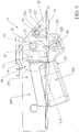
Figure 4 shows a side view of a first and a second portion of the quick fastening means in a disengagement position; -
Figure 5 shows a side view of the quick fastening means in an engagement position between the first and the second portions; -
Figure 6 shows a top view ofFigure 5 ; -
Figure 7 shows a sectional view according to the line VII-VII inFigure 6 ; -
Figure 8 shows a side view of the second portion of the quick fastening means; -
Figure 9 shows a partially sectional side view of the quick fastening means in an engagement position of the first portion with a constraint pivot in a first position in a constraint slot of the first portion, said constraint pivot is engaged in a locking notch of the second portion; -
Figure 10 shows a side view of another side ofFigure 9 ; -
Figure 11 shows the partially sectional side view inFigure 9 with the constraint pivot in a second position in the constraint slot, said constraint pivot is disengaged from the locking notch of the second portion; -
Figure 12 shows a side view of the other side ofFigure 11 . - With reference to the figures listed above, a
lawnmower 1 is noted comprising quick fastening means 9 between afront portion 5 of thelawnmower 1 and afrontal implement 3 of the lawnmower 1 (Figure 1 ). Saidfrontal implement 3 is separably mountable with thefront portion 5 of thelawnmower 1 in the front driving direction of thelawnmower 1 so a s to advantageously permit an operator sitting on thelawnmower 1 to control the operations of thefrontal implement 3. - The
frontal implement 3 can be included in a list of implements comprising for example a cutting plate and a snowplow. - As shown in particular in
Figures 2-3 , the quick fastening means 9 comprise twoportions - A
first portion 100 of the quick fastening means 9 comprises a rotatingportion 21, twobrackets hub 69, anextension 115, alever 125 and arecall spring 450. - Said
first portion 100 of the quick fastening means 9 is rotatably associated with thefront portion 5 of thelawnmower 1 identifying a rotation axis R. Said rotation axis R coincides with an axis of the front wheels of thelawnmower 1, said axis of the front wheels is parallel to a transversal axis T. Said front wheels are rotatably mounted with thefront portion 5 of thelawnmower 1. Saidfirst portion 100 of the quick fastening means 9 is rotatably associated with the axis of the front wheels of thelawnmower 1. - As shown in particular in
Figure 8 , asecond portion 200 of the quick fastening means 9 is fixed to thefrontal implement 3. Saidsecond portion 200 is anarm 200 comprising afirst extremity 203 and asecond extremity 205. Thefirst extremity 203 of thearm 200 is integrally fixed to thefrontal implement 3 of thelawnmower 1. Thesecond extremity 205 of thearm 200 comprises alocking notch 19 and anextension 15 which extends towards the back of thelawnmower 1 along a longitudinal axis L. Saidsecond extremity 205 of thearm 200 is separably mountable in a quick manner with thefirst portion 100 of the quick fastening means 9. - The
arm 200 is a flat bar the main dimensions of which are a length of thearm 200 measured along the longitudinal axis L and a height of thearm 200 measured along a vertical axis V with respect to the ground. Thearm 200 is arranged on a geometric longitudinal plane Λ which is identified by the longitudinal axis L and by the vertical axis V. Thearm 200 is flat since a thickness of thearm 200 which is measured along the transversal axis T has very small dimensions with respect to the height and length of thearm 200. The transversal axis T is parallel to the rotation axis R and to the axis of the front wheels of thelawnmower 1. - The
extension 15 comprises a U-shapedhook slot 17 facing downwards along the vertical axis V. Saidhook slot 17 of theextension 15 of thearm 200 comprises anopening 170 of the U facing downwards to form a hook. - As shown in particular in
Figures 2-7 ,9-12 , said rotatingportion 21 of thefirst portion 100 of the quick fastening means 9 is a folded metal sheet with a U-shaped cross section. The cross section of the rotatingportion 21 is identified by a geometric transversal plane Σ which in turn is identified by the transversal axis T and by the vertical axis V. Said rotatingportion 21 comprises twoparallel sheets outer sheet 25 and aninner sheet 27 and atransversal sheet 29 which is a spacer therebetween which is arranged along the transversal axis T so as to form the U-shaped cross section. Saidtransversal sheet 29 connects an extremity of theouter sheet 25 to an extremity of theinner sheet 27. The extremity of theouter sheet 25 and the extremity of theinner sheet 27 connected by thetransversal sheet 29 face the same direction. Thetransversal sheet 29 permits to keep theouter sheet 25 and theinner sheet 27 at a certain fixed distance. Theouter sheet 25 and theinner sheet 27 are perpendicular to the rotation axis R. - The
outer sheet 25 and theinner sheet 27 of the rotatingportion 21 comprise a respectivetransversal place 31 within which anengaging pivot 41 is mounted. Theengaging pivot 41 is transversely arranged between theouter sheet 25 and theinner sheet 27 of the rotatingportion 21 and theengaging pivot 41 is arranged along a roto-translation axis E which is parallel to the rotation axis R. The roto-translation axis E is at a longitudinal distance D with respect to the rotation axis R so that a center 30 of a longitudinal section of theengaging pivot 41 is at the longitudinal distance D with respect to the rotation axis R. The longitudinal distance D puts the rotation axis R off-axis with respect to the roto-translation axis E. The longitudinal distance D is advantageously adapted to keep a belt between thelawnmower 1 and the frontal implement 3 in tension during the entire rotation of thefirst portion 100 of the quick fastening means 9 about the rotation axis R. - The
hook slot 17 of theextension 15 of thearm 200 is adapted to be separably and rotatably associated with an outer surface of theengaging pivot 41 of the rotatingportion 21. Thehook slot 17 has a longitudinal size comparable to the geometric diameter of the longitudinal section of theengaging pivot 41 as shown in particular inFigures 3-12 . - The
transversal sheet 29 permits to keep theouter sheet 25 and theinner sheet 27 at a transversal distance corresponding to that of the thickness of theextension 15 with thehook slot 17 so that theouter sheet 25 and theinner sheet 27 have a driving function for theextension 15 of thearm 200 and permit to keep thehook slot 17 of thearm 200 in place above the outer surface of theengaging pivot 41 of therotating portion 21 of thefirst portion 100 of the quick fastening means 9. - The
engaging pivot 41 has a transversal size which coincides with the thickness of theextension 15 of thearm 200. - From the
inner sheet 27 of the rotatingportion 21 of thefirst portion 100 of the quick engaging means 9 twobracket lawnmower 1. The twobrackets upper bracket 401 and onelower bracket 402 which are parallel to each other. - The
hub 69 of thefirst portion 100 of the quick fastening means 9 is firmly welded to the rotatingportion 21 by means of the twobracket - The
hub 69 is cylindrical in shape. Saidhub 69 comprises a transversal throughhole 13 which is disposed along the direction of the rotation axis R and is adapted to engage said axis of the front wheel of thelawnmower 1. The rotation axis R passes from a geometric center 10 of a geometric longitudinal section of the transversal throughhole 13 of thehub 69. - The
first portion 100 of the quick fastening means 9 rotates about the rotation axis R passing from a disengagement position which permits the disengagement of the arm 200 (Figures 5, 6 ) to an engagement position which does not permit the disengagement of the arm 200 (Figure 9 ). - In the disengagement position of the
first portion 100 of the quick fastening means 9, as shown inFigures 4-7 , the U-shaped cross section of the rotatingportion 21 faces upwards, namely thetransversal sheet 29 of the rotatingportion 21 faces downwards and permits the insertion from the top of thehook slot 17 of theextension 15 of thearm 200 which is positioned above the outer surface of the engagingpivot 41 until thehook slot 17 completely rests on top of the outer surface of the engagingpivot 41. The insertion from the top of thehook slot 17 is guided within theouter sheet 25 and theinner sheet 27 of the rotatingportion 21. - As shown in
Figures 9-12 , in the engagement position of thefirst portion 100 of the quick fastening means 9, the U-shaped cross section of the rotatingportion 21 faces downwards, namely thetransversal sheet 29 of the rotatingportion 21 faces upwards and does not permit the disengagement of thehook slot 17 of theextension 15 of thearm 200. - During the rotation of the
first portion 100 of the quick fastening means 9 about the rotation axis R, the engagingpivot 41 rotates in turn about the rotation axis R. - The inner surface of the
hook slot 17 of thearm 200 is in sliding contact with the outer surface of the engagingpivot 41 during the rotation of thefirst portion 100 of the quick fastening means 9 about the rotation axis R. Thehook slot 17 has theopening 170 of the U always facing downwards during the passage from the disengagement position to the engagement position of thefirst portion 100 of the quick fastening means 9. - As shown in
Figures 2-3 ,9-12 considering the engagement position of thefirst portion 100 of the quick fastening means 9, thetransversal sheet 29 of the rotatingportion 21 of thefirst portion 100 of the quick fastening means 9 extends in the direction of the longitudinal axis L with theextension 115 of thefirst portion 100 of the quick fastening means 9. Theextension 115 is directed towards the back of thelawnmower 1 when thefirst portion 100 of the quick fastening means 9 is in the engagement position. - The rotating
portion 21 comprises a transversal hinge throughhole 129 adapted to rotatably mount thelever 125. In particular, thetransversal sheet 29 of the rotatingportion 21 mounts ahinge cylinder 129 of the rotatingportion 21 which comprises a transversal hinge throughhole 120. Thelever 125 of thefirst portion 100 of the quick fastening means 9 comprises twohinge places 195 which overlap the transversal hinge throughhole 120 and permit ahinge pivot 20 of the rotatingportion 21 to pass through the twohinge places 195 of thelever 125 and the transversal hinge throughhole 120 of the rotating portion21, thus pivoting thelever 125 with the rotatingportion 21. - The
lever 125 is a sheet comprising anelongated portion 126 which overlaps, at least for one portion, theextension 115 of the rotatingportion 21. Thelever 125 rotates on thehinge pivot 20 of the rotatingportion 21 and is constrained in the rotational movement by theelongated portion 126 adapted to enter in contact with theextension 115 of the rotatingportion 21. - Another constraint of the movement of the
lever 125 is given by aconstraint pivot 95 of the rotatingportion 21. - The
transversal sheet 29 extends in afirst extension 121 outwards in a direction parallel to the rotation axis R, as shown in particular inFigures 2 and3 . Saidfirst extension 121 is adapted to be pressed by a user who wants to rotate the rotatingportion 21. Thefirst extension 121 also serves the function as stroke-end stop for the rotatingportion 21, as seen inFigures 2 and11 , in which thefirst extension 121 abuts against an upper surface of thearm 200. - The
lower bracket 402 extends in asecond extension 122 outwards in a direction parallel to the rotation axis R, as shown in particular inFigures 2 and3 . Saidsecond extension 122 serves the function to constrain the clockwise rotation of the rotatingportion 21 about the rotation axis R, when thefirst portion 100 is at the disengagement position, as shown inFigures 5 and 6 . In fact, thesecond extension 122 of thelower bracket 402 of thefirst portion 100 abuts against a lower surface of thearm 200. - Advantageously, said
first extension 121 andsecond extension 122 are pressed by a foot of the user without having to lean and without having to use the hands. - The
outer sheet 25 and the inner sheet 26 of the rotatingportion 21 comprise aconstraint slit 255 which is shaped as a circumference arc. Theouter sheet 25 comprises an outer constraint slit 255 corresponding on the other side to an inner constraint slit 255 which is obtained in theinner sheet 27 of the rotating portion. - The
lever 125 comprises twoconstraint places 155 which overlap the constraint slits 255 of the rotatingportion 21 and permit theconstraint pivot 95 to pass through and pivot the rotatingportion 21 with thelever 125, thus constraining the movement of thelever 125 within the circumference arc identified by the constraint slit 255 of the rotatingportion 21. - The
lever 125 rotates about thehinge pivot 20 of the rotatingportion 21 from an abutment position of theelongated portion 126 of thelever 125 against theextension 115 of the rotatingportion 21 which coincides with a first stop position of theconstraint pivot 95 at oneextremity 256 of the two extremities of the constraint slit 255, to a second stop position of theconstraint pivot 95 at theother extremity 257 of the constraint slit 255. - The
constraint pivot 95 is adapted to enter the lockingnotch 19 of thearm 200 when theconstraint pivot 95 is at a first position inside the constraint slit 255, saidrecall spring 450 keeps the first position of theconstraint pivot 95 in place. - The
second portion 200, namely thearm 200 of the fastening means 9 comprises the lockingnotch 19 which is placed in an opposing direction with respect to theextension 15 comprising thehook slot 17. Said lockingnotch 19 of thearm 200 of the fastening means 9 comprises a lead-inportion 45, ashoulder portion 49 and a further recessedportion 53 which follows theshoulder portion 49, in which said further recessedportion 53 is obtained in the direction of theextension 15 comprising the hook-shapedslot 17. - When the
first portion 100 of the quick fastening means 9 is in the disengagement position and is constrained to the clockwise rotation by the abutment of thearm 200 against thesecond extension 122, theportion 100 may be rotated by pressing thefirst extension 121 of thetransversal sheet 29 of thefirst portion 100 until theconstraint pivot 95 passes from the second stop position (Figure 11 ) to the first stop position (Figure 9 ) so that theconstraint pivot 95 penetrates the lockingnotch 19 to be positioned inside the further recessedportion 53 of the lockingnotch 19, thus fastening thearm 200 with thefirst portion 100 of the quick fastening means 9 and thus fastening thefront portion 5 of thelawnmower 1 with the frontal implement 3 in an advantageously safe and stable manner. - The first stop position of the
constraint pivot 95 is kept stable by means of the recall spring 450 (Figures 9 and 10 ). - The
lower bracket 402 of the rotatingportion 21 integrally mounts afirst extremity 451 of therecall spring 450. Asecond extremity 452 of therecall spring 450 is integrally mounted with thelever 125. In particular, thesecond extremity 452 of therecall spring 450 is engaged with thelever 125 by means of theconstraint pivot 95 in turn arranged at theconstraint place 155. Theconstraint place 155 is opposite to theelongated portion 126 of thelever 125 with respect to thehinge pivot 20. By pressing theelongated portion 126 of thelever 125 downwards to abut against theextension 115 of the rotatingportion 21, theconstraint pivot 95 passes from the first stop position (Figure 9 ) to the second stop position (Figure 11 ) leaving the lockingnotch 19 of thearm 200 and permitting thefirst portion 100 of the quick fastening means 9 to rotate about the rotation axis R to the constraint given by the abutment of thearm 200 against thesecond extension 122, advantageously permitting thefirst portion 100 of the quick fastening means 9 to pass from the engagement position to the disengagement position and disengage thearm 200 from thefirst portion 100 of the quick fastening means 9. - As regards the operation of the quick fastening means 9, starting from a disengagement position of the
first portion 100 of the quick fastening means 9 in which thehook slot 17 of thearm 200 engages the engagingpivot 41 of the rotatingportion 21, thefirst portion 100 of the quick fastening means 9 rotates about the rotation axis R to an engagement position in which thetransversal sheet 29 of the rotating portion locks the escaping of thehook slot 17 of theextension 15 of thearm 200 out of the engagingpivot 41 of the rotatingportion 21 of thefirst portion 100 of the quick fastening means 9. In said engagement position of thefirst portion 100 of the quick fastening means 9, theconstraint pivot 95 passes to the first stop position inside the constraint slit 255 which coincides with the position of theconstraint pivot 95 inside the further recessedportion 53 in the lockingnotch 19 of thearm 200. Therecall spring 450 passes from a resting position, in which theelongated portion 126 of thelever 125 is raised from theextension 115 of the rotatingportion 21 and theconstraint pivot 95 is at the first stop position inside the constraint slit 255 of the rotatingportion 21, to an elongated position of therecall spring 450, in which theelongated portion 126 of thelever 125 abuts against theextension 115 of the rotatingportion 21 for then returning to a resting position in which theelongated portion 126 of thelever 125 is raised from theextension 115 of the rotatingportion 21 and theconstraint pivot 95 is in the second stop position inside of the constraint slit 255 of the rotatingportion 21. In said second stop position inside the constraint slit 255 of the rotatingportion 21, theconstraint pivot 95 is taken out of the lockingnotch 19 of thearm 200 thus permitting thefirst portion 100 of the quick fastening means 9 to rotate about the rotation axis R and pass from the engagement position to the disengagement position of thefirst portion 100 of the quick fastening means 9 and permit thearm 200 to be disengaged from thefirst portion 100 of the quick fastening means 9 and permit the disengagement of the frontal implement 3 from thefront portion 5 of thelawnmower 1. - Alternatively, said rotation axis R is different from the axis of the front wheel of the
lawnmower 1, but said rotation axis R is placed along a direction parallel to the axis of the front wheel of thelawnmower 1. - Again alternatively, the rotating
portion 21 is provided to only comprise thelower bracket 402 which welds thehub 69. Saidlower bracket 402 is necessary and advantageous to connect an extremity of therecall spring 450. - A further alternative includes the rotating
portion 21 comprising only one constraint slit 255 which is shaped as a circumference arc, and theconstraint pivot 95 of thefirst portion 100 engaging thelever 125 with the constraint slit 255 of the rotatingportion 21 constraining the movement of thelever 125 adapted to rotate about thehinge pivot 20. - Advantageously, the manufacture of the
lawnmower 1 comprising the fastening means 9 between afront portion 5 of thelawnmower 1 and the frontal implement 3 of thelawnmower 1 allows a quick connection betweenlawnmower 1 and frontal implement 3, which is not wedged. The fastening means 9 of the lawnmower advantageously also permit a safe connection in view of vibrations and jamming or ground resistances. - In order to uncouple the frontal implement 3 from the
lawnmower 1, it is advantageously sufficient a single easy operation of pressing thelever 125 until it is in abutment against theextension 115 of the rotatingportion 21, making theconstraint pivot 95 leave the lockingnotch 19 of thearm 200, rotating thefirst portion 100 about the rotation axis R with the same movement. - Advantageously, the quick fastening means 9 are smaller and compact in size and easier to be handled.
Claims (6)
- Lawnmower (1) comprising a quick fastening means (9) between a front portion (5) of the lawnmower (1) and a frontal implement (3) of the lawnmower (1), said frontal implement (3) is separably mountable with the front portion (5) of the lawnmower (1), said quick fastening means (9) comprise a first portion (100) and a second portion (200), said first portion (100) of the quick fastening means (9) is rotatably associated with the front portion (5) of the lawnmower (1) identifying a rotation axis (R), said second portion (200) of the quick fastening means (9) is fixed with the frontal implement (3) of the lawnmower (1), said first portion (100) of the quick fastening means (9) comprise a rotating portion (21), at least one bracket (401, 402), a hub (69), an extension (115), said rotating portion (21) of the first portion (100) of the quick fastening means (9) is a folded sheet with a transversal section of U-shape and comprises an outer sheet (25) and an inner sheet (27) that are parallel to each other and a transversal sheet (29) which is a spacer between the outer sheet (25) and the inner sheet (27), said rotating portion (21) comprises an engaging pivot (41) which is transversely disposed between the outer sheet (25) and the inner sheet (27) of the rotating portion (21) along a roto-translation axis (E) which is parallel with the rotation axis (R), said roto-translation axis (E) is arranged to a longitudinal distance (D) with respect to the rotation axis (R), said second portion (200) of the quick fastening means (9) comprises a first extremity (203) integrally fixed to the frontal implement (3) of the lawnmower (1) and a second extremity (205) which comprises a locking notch (19) and an extension (15) which extends towards the back of the lawnmower (1) along a longitudinal axis (L), said second extremity (205) of the second portion (200) of the quick fastening means (9) is separably and quickly mountable with the first portion (100) of the quick fastening means (9), the extension (15) comprises a hook slot (17) of U-shape facing downwards along the vertical axis (V), said hook slot (17) is adapted to be separably and rotatably associated with an outer surface of the engaging pivot (41) of the rotating portion (21), the locking notch (19) is disposed in a direction opposed to the extension (15) comprising the hook slot (17), said hub (69) of the first portion (100) of the quick fastening means (9) is firmly welded with the rotating portion (21) by means of said at least one bracket (401, 402), said hub (69) comprises a transversal through hole (13) which is disposed along the direction of the rotation axis (R) and is adapted to engage said axis of the front wheel of the lawnmower (1), said extension (115) extends from the rotating portion (21) towards the direction of the longitudinal axis (L), the first portion (100) of the quick fastening means (9) rotates about the rotation axis (R) passing from a disengagement position which permits the disengagement of the second portion (200) to an engagement position which does not permit the disengagement of the second portion (200), during a rotation of the first portion (100) of the quick fastening means (9) about the rotation axis (R) the engaging pivot (41) rotates about the rotation axis (R) in its turn, characterized in that said first portion (100) of the quick fastening means (9) comprises a lever (125) and a recall spring (450), said lever (125) is pivoted with the rotating portion (21) by means of a hinge pivot (20) of the first portion (100), the lever (125) comprises an elongated portion (126) which overlaps for at least a portion to the extension (115) of the rotating portion (21), the rotational movement of the lever (125) rotating about the hinge pivot (20) is constrained by the elongated portion (126) adapted to enter in contact with the extension (115) of the rotating portion (21), the rotating portion (21) comprises at least one constraint slit (255) which is of circumference arc shape, a constraint pivot (95) of the first portion (100) engages the lever (125) and the constraint slit (255) of the rotating portion (21) constraining the rotational movement of the lever (125) within the circumference arc identified by the constraint slit (255) of the rotating portion (21), the constraint pivot (95) is adapted to enter the locking notch (19) of the second portion (200) of the quick fastening means (9) when the constraint pivot (95) is at a first position inside the constraint slit (255), said recall spring (450) keeps in place the constraint pivot (95) at the first position inside the constraint slit (255).
- Lawnmower (1) according to the claim 1, characterized in that the lever (125) rotates about the hinge pivot (20) from an abutment position of the elongated portion (126) of the lever (125) against the extension (115) of the rotating portion (21) which coincides with a second stop position of the constraint pivot (95) at one extremity (257) of two extremities of the constraint slit (255), to a first stop position of the constraint pivot (95) at one other extremity (256) of the constraint slit (255).
- Lawnmower (1) according to anyone of the claims 1 or 2, characterized in that when the first portion (100) of the quick fastening means (9) is at the engagement position, it is possible to rotate the lever (125) of the first portion (100) by pressing the elongated portion (126) of the lever (125) towards the extension (115) of the rotating portion (21) until the constraint pivot (95) passes from one first stop position to one second stop position so that the constraint pivot (95) leaves the locking notch (19) permitting the rotation of the first portion (100) until the first portion (100) passes to one disengagement position and permits the disengagement of the frontal implement 3 from the front portion 5 of the lawnmower 1.
- Lawnmower (1) according to anyone of the claims 1-3, characterized in that said at least one bracket (401, 402) is a lower bracket (402) of the first portion (100) of the quick fastening means (9), said lower bracket (402) integrally mounts a first extremity (451) of the recall spring (450), a second extremity (452) of the recall spring (450) is integrally mounted with the lever (125).
- Lawnmower (1) according to the claim 4, characterized in that the second extremity (452) of the recall spring (450) engages the lever (125) by means of the constraint pivot (95) which is disposed into a constraint place (155) of the lever (125), said constraint place (155) of the lever (125) is opposite the elongated portion (126) of the lever (125) with respect to the hinge pivot (20).
- Lawnmower (1) according to anyone of the claims 4 or 5, characterized in that said transversal sheet (29) extends with a first extension (121) outwards towards a direction which is parallel to the rotation axis (R), said first extension (121) is adapted to be pressed for rotating the rotating portion (21), the first extension (121) is adapted to abut against an upper surface of the second portion (200) constraining the rotation of the first portion (100), said lower bracket (402) extends with a second extension (122) outwards towards a direction which is parallel to the rotation axis (R), said second extension (122) constraints the rotation of the rotating portion (21) about the rotation axis (R), the second extension (122) of the lower bracket (402) of the first portion 100 is adapted to abut against a lower surface of the second portion (200) constraining the rotation of the first portion (100).
Applications Claiming Priority (1)
| Application Number | Priority Date | Filing Date | Title |
|---|---|---|---|
| ITUA2016A001422A ITUA20161422A1 (en) | 2016-03-07 | 2016-03-07 | Mower with quick coupling for front accessories. |
Publications (2)
| Publication Number | Publication Date |
|---|---|
| EP3216338A1 true EP3216338A1 (en) | 2017-09-13 |
| EP3216338B1 EP3216338B1 (en) | 2018-12-05 |
Family
ID=56203547
Family Applications (1)
| Application Number | Title | Priority Date | Filing Date |
|---|---|---|---|
| EP17159116.7A Active EP3216338B1 (en) | 2016-03-07 | 2017-03-03 | Lawnmower with quick fastening for frontal implements |
Country Status (2)
| Country | Link |
|---|---|
| EP (1) | EP3216338B1 (en) |
| IT (1) | ITUA20161422A1 (en) |
Cited By (1)
| Publication number | Priority date | Publication date | Assignee | Title |
|---|---|---|---|---|
| EP3682722A1 (en) * | 2019-01-18 | 2020-07-22 | AGCO International GmbH | Improved hay tool |
Citations (6)
| Publication number | Priority date | Publication date | Assignee | Title |
|---|---|---|---|---|
| US3958399A (en) * | 1975-02-18 | 1976-05-25 | Sperry Rand Corporation | Header attachment structure |
| US4280317A (en) * | 1980-04-16 | 1981-07-28 | Sperry Corporation | Adjustable coupling apparatus |
| WO2007136313A1 (en) | 2006-05-18 | 2007-11-29 | Ggp Sweden Ab | Implement carrier |
| US7302765B1 (en) | 2004-09-20 | 2007-12-04 | Quick Attach Attachments, Inc. | Implement attaching apparatus |
| US20100170212A1 (en) | 2007-01-12 | 2010-07-08 | Johansson Joergen | Adjustable drive axle for a lawn mower |
| EP2676534A1 (en) * | 2012-06-18 | 2013-12-25 | GGP Sweden AB | Fastening means |
-
2016
- 2016-03-07 IT ITUA2016A001422A patent/ITUA20161422A1/en unknown
-
2017
- 2017-03-03 EP EP17159116.7A patent/EP3216338B1/en active Active
Patent Citations (7)
| Publication number | Priority date | Publication date | Assignee | Title |
|---|---|---|---|---|
| US3958399A (en) * | 1975-02-18 | 1976-05-25 | Sperry Rand Corporation | Header attachment structure |
| US4280317A (en) * | 1980-04-16 | 1981-07-28 | Sperry Corporation | Adjustable coupling apparatus |
| US7302765B1 (en) | 2004-09-20 | 2007-12-04 | Quick Attach Attachments, Inc. | Implement attaching apparatus |
| WO2007136313A1 (en) | 2006-05-18 | 2007-11-29 | Ggp Sweden Ab | Implement carrier |
| US20100170212A1 (en) | 2007-01-12 | 2010-07-08 | Johansson Joergen | Adjustable drive axle for a lawn mower |
| EP2676534A1 (en) * | 2012-06-18 | 2013-12-25 | GGP Sweden AB | Fastening means |
| EP2676534B1 (en) | 2012-06-18 | 2015-04-08 | GGP Sweden AB | Fastening means |
Cited By (2)
| Publication number | Priority date | Publication date | Assignee | Title |
|---|---|---|---|---|
| EP3682722A1 (en) * | 2019-01-18 | 2020-07-22 | AGCO International GmbH | Improved hay tool |
| US11357168B2 (en) | 2019-01-18 | 2022-06-14 | Agco Feucht Gmbh | Towed implement that compensates for unbalanced loads caused by offset centre of gravity |
Also Published As
| Publication number | Publication date |
|---|---|
| EP3216338B1 (en) | 2018-12-05 |
| ITUA20161422A1 (en) | 2017-09-07 |
Similar Documents
| Publication | Publication Date | Title |
|---|---|---|
| US7275753B1 (en) | Towing dolly cradle assembly | |
| JP5668142B2 (en) | Vertical adjustment device for vehicle seat | |
| EP2191870B1 (en) | Blocking device with cam for belaying a fixed rope | |
| US7437981B2 (en) | Modular guard system and apparatus for a power saw | |
| US5636504A (en) | Handle assembly for outdoor power equipment | |
| EP3216338B1 (en) | Lawnmower with quick fastening for frontal implements | |
| US9254580B2 (en) | Guard system for a power saw | |
| EP0021885B1 (en) | Handle for operating a valve | |
| FR3029957A1 (en) | UNLOCKING DEVICE FOR A VEHICLE HOOD | |
| DK144029B (en) | SEEDS WITH PENDING GIRL, SPECIAL FOR MOTOR VEHICLES | |
| US2537553A (en) | Combined bumper grill hitch | |
| US9073460B2 (en) | Road finisher and seat console | |
| EP2676534B1 (en) | Fastening means | |
| JP2011218550A (en) | Bevel adjustment device for circular saw | |
| US20110318999A1 (en) | Hand Tool Protection Device | |
| EP0701770A1 (en) | Locking mechanism for agricultural machine | |
| US6910275B2 (en) | Cable-stripping tool | |
| EP2626178B1 (en) | Cutting machine | |
| FR2584913A1 (en) | DEMIBRABLE HOPPER HANDLE | |
| EP3099155B1 (en) | Height-adjustable lawnmower handle | |
| GB2426748A (en) | Locking device for fifth wheel coupling | |
| US2213434A (en) | Supporting bracket | |
| EP3436314A1 (en) | Adjustable seat structure of a vehicle seat, comprising a seat belt buckle part | |
| EP2353812A1 (en) | Chain Saw | |
| US20050284707A1 (en) | Wheel securing means |
Legal Events
| Date | Code | Title | Description |
|---|---|---|---|
| PUAI | Public reference made under article 153(3) epc to a published international application that has entered the european phase |
Free format text: ORIGINAL CODE: 0009012 |
|
| STAA | Information on the status of an ep patent application or granted ep patent |
Free format text: STATUS: THE APPLICATION HAS BEEN PUBLISHED |
|
| AK | Designated contracting states |
Kind code of ref document: A1 Designated state(s): AL AT BE BG CH CY CZ DE DK EE ES FI FR GB GR HR HU IE IS IT LI LT LU LV MC MK MT NL NO PL PT RO RS SE SI SK SM TR |
|
| AX | Request for extension of the european patent |
Extension state: BA ME |
|
| RAP1 | Party data changed (applicant data changed or rights of an application transferred) |
Owner name: STIGA S.P.A. IN BREVE ANCHE ST. S.P.A. |
|
| STAA | Information on the status of an ep patent application or granted ep patent |
Free format text: STATUS: REQUEST FOR EXAMINATION WAS MADE |
|
| 17P | Request for examination filed |
Effective date: 20180312 |
|
| RBV | Designated contracting states (corrected) |
Designated state(s): AL AT BE BG CH CY CZ DE DK EE ES FI FR GB GR HR HU IE IS IT LI LT LU LV MC MK MT NL NO PL PT RO RS SE SI SK SM TR |
|
| GRAP | Despatch of communication of intention to grant a patent |
Free format text: ORIGINAL CODE: EPIDOSNIGR1 |
|
| STAA | Information on the status of an ep patent application or granted ep patent |
Free format text: STATUS: GRANT OF PATENT IS INTENDED |
|
| RIC1 | Information provided on ipc code assigned before grant |
Ipc: A01D 43/10 20060101AFI20180528BHEP Ipc: A01B 59/06 20060101ALI20180528BHEP |
|
| INTG | Intention to grant announced |
Effective date: 20180621 |
|
| GRAS | Grant fee paid |
Free format text: ORIGINAL CODE: EPIDOSNIGR3 |
|
| GRAA | (expected) grant |
Free format text: ORIGINAL CODE: 0009210 |
|
| STAA | Information on the status of an ep patent application or granted ep patent |
Free format text: STATUS: THE PATENT HAS BEEN GRANTED |
|
| AK | Designated contracting states |
Kind code of ref document: B1 Designated state(s): AL AT BE BG CH CY CZ DE DK EE ES FI FR GB GR HR HU IE IS IT LI LT LU LV MC MK MT NL NO PL PT RO RS SE SI SK SM TR |
|
| REG | Reference to a national code |
Ref country code: GB Ref legal event code: FG4D |
|
| REG | Reference to a national code |
Ref country code: CH Ref legal event code: EP |
|
| REG | Reference to a national code |
Ref country code: AT Ref legal event code: REF Ref document number: 1071864 Country of ref document: AT Kind code of ref document: T Effective date: 20181215 |
|
| REG | Reference to a national code |
Ref country code: IE Ref legal event code: FG4D |
|
| REG | Reference to a national code |
Ref country code: DE Ref legal event code: R096 Ref document number: 602017001137 Country of ref document: DE |
|
| REG | Reference to a national code |
Ref country code: SE Ref legal event code: TRGR |
|
| REG | Reference to a national code |
Ref country code: NL Ref legal event code: MP Effective date: 20181205 |
|
| REG | Reference to a national code |
Ref country code: AT Ref legal event code: MK05 Ref document number: 1071864 Country of ref document: AT Kind code of ref document: T Effective date: 20181205 |
|
| REG | Reference to a national code |
Ref country code: LT Ref legal event code: MG4D |
|
| PG25 | Lapsed in a contracting state [announced via postgrant information from national office to epo] |
Ref country code: ES Free format text: LAPSE BECAUSE OF FAILURE TO SUBMIT A TRANSLATION OF THE DESCRIPTION OR TO PAY THE FEE WITHIN THE PRESCRIBED TIME-LIMIT Effective date: 20181205 Ref country code: LV Free format text: LAPSE BECAUSE OF FAILURE TO SUBMIT A TRANSLATION OF THE DESCRIPTION OR TO PAY THE FEE WITHIN THE PRESCRIBED TIME-LIMIT Effective date: 20181205 Ref country code: HR Free format text: LAPSE BECAUSE OF FAILURE TO SUBMIT A TRANSLATION OF THE DESCRIPTION OR TO PAY THE FEE WITHIN THE PRESCRIBED TIME-LIMIT Effective date: 20181205 Ref country code: LT Free format text: LAPSE BECAUSE OF FAILURE TO SUBMIT A TRANSLATION OF THE DESCRIPTION OR TO PAY THE FEE WITHIN THE PRESCRIBED TIME-LIMIT Effective date: 20181205 Ref country code: BG Free format text: LAPSE BECAUSE OF FAILURE TO SUBMIT A TRANSLATION OF THE DESCRIPTION OR TO PAY THE FEE WITHIN THE PRESCRIBED TIME-LIMIT Effective date: 20190305 Ref country code: FI Free format text: LAPSE BECAUSE OF FAILURE TO SUBMIT A TRANSLATION OF THE DESCRIPTION OR TO PAY THE FEE WITHIN THE PRESCRIBED TIME-LIMIT Effective date: 20181205 Ref country code: NO Free format text: LAPSE BECAUSE OF FAILURE TO SUBMIT A TRANSLATION OF THE DESCRIPTION OR TO PAY THE FEE WITHIN THE PRESCRIBED TIME-LIMIT Effective date: 20190305 Ref country code: AT Free format text: LAPSE BECAUSE OF FAILURE TO SUBMIT A TRANSLATION OF THE DESCRIPTION OR TO PAY THE FEE WITHIN THE PRESCRIBED TIME-LIMIT Effective date: 20181205 |
|
| PG25 | Lapsed in a contracting state [announced via postgrant information from national office to epo] |
Ref country code: GR Free format text: LAPSE BECAUSE OF FAILURE TO SUBMIT A TRANSLATION OF THE DESCRIPTION OR TO PAY THE FEE WITHIN THE PRESCRIBED TIME-LIMIT Effective date: 20190306 Ref country code: AL Free format text: LAPSE BECAUSE OF FAILURE TO SUBMIT A TRANSLATION OF THE DESCRIPTION OR TO PAY THE FEE WITHIN THE PRESCRIBED TIME-LIMIT Effective date: 20181205 Ref country code: RS Free format text: LAPSE BECAUSE OF FAILURE TO SUBMIT A TRANSLATION OF THE DESCRIPTION OR TO PAY THE FEE WITHIN THE PRESCRIBED TIME-LIMIT Effective date: 20181205 |
|
| PG25 | Lapsed in a contracting state [announced via postgrant information from national office to epo] |
Ref country code: NL Free format text: LAPSE BECAUSE OF FAILURE TO SUBMIT A TRANSLATION OF THE DESCRIPTION OR TO PAY THE FEE WITHIN THE PRESCRIBED TIME-LIMIT Effective date: 20181205 |
|
| PG25 | Lapsed in a contracting state [announced via postgrant information from national office to epo] |
Ref country code: PT Free format text: LAPSE BECAUSE OF FAILURE TO SUBMIT A TRANSLATION OF THE DESCRIPTION OR TO PAY THE FEE WITHIN THE PRESCRIBED TIME-LIMIT Effective date: 20190405 Ref country code: PL Free format text: LAPSE BECAUSE OF FAILURE TO SUBMIT A TRANSLATION OF THE DESCRIPTION OR TO PAY THE FEE WITHIN THE PRESCRIBED TIME-LIMIT Effective date: 20181205 Ref country code: CZ Free format text: LAPSE BECAUSE OF FAILURE TO SUBMIT A TRANSLATION OF THE DESCRIPTION OR TO PAY THE FEE WITHIN THE PRESCRIBED TIME-LIMIT Effective date: 20181205 |
|
| PG25 | Lapsed in a contracting state [announced via postgrant information from national office to epo] |
Ref country code: SK Free format text: LAPSE BECAUSE OF FAILURE TO SUBMIT A TRANSLATION OF THE DESCRIPTION OR TO PAY THE FEE WITHIN THE PRESCRIBED TIME-LIMIT Effective date: 20181205 Ref country code: RO Free format text: LAPSE BECAUSE OF FAILURE TO SUBMIT A TRANSLATION OF THE DESCRIPTION OR TO PAY THE FEE WITHIN THE PRESCRIBED TIME-LIMIT Effective date: 20181205 Ref country code: IS Free format text: LAPSE BECAUSE OF FAILURE TO SUBMIT A TRANSLATION OF THE DESCRIPTION OR TO PAY THE FEE WITHIN THE PRESCRIBED TIME-LIMIT Effective date: 20190405 Ref country code: EE Free format text: LAPSE BECAUSE OF FAILURE TO SUBMIT A TRANSLATION OF THE DESCRIPTION OR TO PAY THE FEE WITHIN THE PRESCRIBED TIME-LIMIT Effective date: 20181205 Ref country code: SM Free format text: LAPSE BECAUSE OF FAILURE TO SUBMIT A TRANSLATION OF THE DESCRIPTION OR TO PAY THE FEE WITHIN THE PRESCRIBED TIME-LIMIT Effective date: 20181205 |
|
| REG | Reference to a national code |
Ref country code: DE Ref legal event code: R097 Ref document number: 602017001137 Country of ref document: DE |
|
| PLBE | No opposition filed within time limit |
Free format text: ORIGINAL CODE: 0009261 |
|
| STAA | Information on the status of an ep patent application or granted ep patent |
Free format text: STATUS: NO OPPOSITION FILED WITHIN TIME LIMIT |
|
| PG25 | Lapsed in a contracting state [announced via postgrant information from national office to epo] |
Ref country code: SI Free format text: LAPSE BECAUSE OF FAILURE TO SUBMIT A TRANSLATION OF THE DESCRIPTION OR TO PAY THE FEE WITHIN THE PRESCRIBED TIME-LIMIT Effective date: 20181205 Ref country code: DK Free format text: LAPSE BECAUSE OF FAILURE TO SUBMIT A TRANSLATION OF THE DESCRIPTION OR TO PAY THE FEE WITHIN THE PRESCRIBED TIME-LIMIT Effective date: 20181205 Ref country code: MC Free format text: LAPSE BECAUSE OF FAILURE TO SUBMIT A TRANSLATION OF THE DESCRIPTION OR TO PAY THE FEE WITHIN THE PRESCRIBED TIME-LIMIT Effective date: 20181205 |
|
| 26N | No opposition filed |
Effective date: 20190906 |
|
| PG25 | Lapsed in a contracting state [announced via postgrant information from national office to epo] |
Ref country code: LU Free format text: LAPSE BECAUSE OF NON-PAYMENT OF DUE FEES Effective date: 20190303 |
|
| REG | Reference to a national code |
Ref country code: BE Ref legal event code: MM Effective date: 20190331 |
|
| PG25 | Lapsed in a contracting state [announced via postgrant information from national office to epo] |
Ref country code: IE Free format text: LAPSE BECAUSE OF NON-PAYMENT OF DUE FEES Effective date: 20190303 |
|
| PG25 | Lapsed in a contracting state [announced via postgrant information from national office to epo] |
Ref country code: BE Free format text: LAPSE BECAUSE OF NON-PAYMENT OF DUE FEES Effective date: 20190331 |
|
| PG25 | Lapsed in a contracting state [announced via postgrant information from national office to epo] |
Ref country code: TR Free format text: LAPSE BECAUSE OF FAILURE TO SUBMIT A TRANSLATION OF THE DESCRIPTION OR TO PAY THE FEE WITHIN THE PRESCRIBED TIME-LIMIT Effective date: 20181205 |
|
| PG25 | Lapsed in a contracting state [announced via postgrant information from national office to epo] |
Ref country code: MT Free format text: LAPSE BECAUSE OF NON-PAYMENT OF DUE FEES Effective date: 20190303 |
|
| REG | Reference to a national code |
Ref country code: CH Ref legal event code: PL |
|
| PG25 | Lapsed in a contracting state [announced via postgrant information from national office to epo] |
Ref country code: CH Free format text: LAPSE BECAUSE OF NON-PAYMENT OF DUE FEES Effective date: 20200331 Ref country code: LI Free format text: LAPSE BECAUSE OF NON-PAYMENT OF DUE FEES Effective date: 20200331 |
|
| PG25 | Lapsed in a contracting state [announced via postgrant information from national office to epo] |
Ref country code: CY Free format text: LAPSE BECAUSE OF FAILURE TO SUBMIT A TRANSLATION OF THE DESCRIPTION OR TO PAY THE FEE WITHIN THE PRESCRIBED TIME-LIMIT Effective date: 20181205 |
|
| PG25 | Lapsed in a contracting state [announced via postgrant information from national office to epo] |
Ref country code: HU Free format text: LAPSE BECAUSE OF FAILURE TO SUBMIT A TRANSLATION OF THE DESCRIPTION OR TO PAY THE FEE WITHIN THE PRESCRIBED TIME-LIMIT; INVALID AB INITIO Effective date: 20170303 |
|
| PG25 | Lapsed in a contracting state [announced via postgrant information from national office to epo] |
Ref country code: MK Free format text: LAPSE BECAUSE OF FAILURE TO SUBMIT A TRANSLATION OF THE DESCRIPTION OR TO PAY THE FEE WITHIN THE PRESCRIBED TIME-LIMIT Effective date: 20181205 |
|
| PGFP | Annual fee paid to national office [announced via postgrant information from national office to epo] |
Ref country code: FR Payment date: 20230323 Year of fee payment: 7 |
|
| PGFP | Annual fee paid to national office [announced via postgrant information from national office to epo] |
Ref country code: SE Payment date: 20230323 Year of fee payment: 7 Ref country code: IT Payment date: 20230324 Year of fee payment: 7 Ref country code: GB Payment date: 20230322 Year of fee payment: 7 |
|
| P01 | Opt-out of the competence of the unified patent court (upc) registered |
Effective date: 20230421 |
|
| PGFP | Annual fee paid to national office [announced via postgrant information from national office to epo] |
Ref country code: DE Payment date: 20230530 Year of fee payment: 7 |