US1237496A - Telegraphone. - Google Patents
Telegraphone. Download PDFInfo
- Publication number
- US1237496A US1237496A US63188711A US1911631887A US1237496A US 1237496 A US1237496 A US 1237496A US 63188711 A US63188711 A US 63188711A US 1911631887 A US1911631887 A US 1911631887A US 1237496 A US1237496 A US 1237496A
- Authority
- US
- United States
- Prior art keywords
- frame
- reel
- reels
- recording body
- machine
- Prior art date
- Legal status (The legal status is an assumption and is not a legal conclusion. Google has not performed a legal analysis and makes no representation as to the accuracy of the status listed.)
- Expired - Lifetime
Links
Images


Classifications
-
- G—PHYSICS
- G11—INFORMATION STORAGE
- G11B—INFORMATION STORAGE BASED ON RELATIVE MOVEMENT BETWEEN RECORD CARRIER AND TRANSDUCER
- G11B15/00—Driving, starting or stopping record carriers of filamentary or web form; Driving both such record carriers and heads; Guiding such record carriers or containers therefor; Control thereof; Control of operating function
- G11B15/18—Driving; Starting; Stopping; Arrangements for control or regulation thereof
- G11B15/46—Controlling, regulating, or indicating speed
- G11B15/54—Controlling, regulating, or indicating speed by stroboscope; by tachometer
Definitions
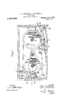
- Figure 1 is a side view of the main parts of a telegraphone apparatus, embodying our improve ments, in one form.
- Fig. 2 is a horizontal section taken on the line 2-2 of Fig. 1.
- Fig. 3 is a plan view of the parts shown in Fig. 1,'the cover of the wooden case being removed.
- Fig. 4 is a detailed view of the two reels upon which the recording body is wound, together with the removable frame, and handle therefor, and automatic locking means.
- Fig. 5 is a detailed view of substantially the same parts as shown in Fig. 4, but taken at right angles thereto, and including the movable talking head.
- Fig. 1 is a side view of the main parts of a telegraphone apparatus, embodying our improve ments, in one form.
- Fig. 2 is a horizontal section taken on the line 2-2 of Fig. 1.
- Fig. 3 is a plan view of the parts shown in Fig. 1,'the cover of the wooden case being removed.
- FIG. 6 is a side view of one of the reels, showing in detail thespecial mechanism therein.
- Fig. 7 is a detailed view showing the working parts of our improved indicator, and automatic stop mechanism.
- Fig. 8 is a vertical section Application filed June a, 1911. Serial no. 681,887.
- Fig. 9 is a detailed view showing the operating mechanism for moving the talking head.
- Fig. 10 is a similar View taken at right angles to Fig. 9.
- Fig. 11 is a vertical section of a talking head, taken on the line 1111, of Fig. 13.
- 'Fig. 12 is a transverse section of the talking head taken on the line 12-12 of Fig. 13.
- Fig. 13 is a detailed transverse section through the talking head, taken substantially on the line 13-18 of Fig. 12.
- 1 represents suitable frame work for carrying and holding the various parts in operative position.
- 2 represents an electric motor which drives a shaft 3, which in turn drives a pulley 4, over which passes a belt 5.
- the belt 5 passes about the pulley 4, around two idler pulleys 6 and 7, and about a pulley 8 secured to a shaft 9 (see Fig. 2).
- the belt 5 may be tightened by adjustably setting an arm 10 (see Fig. 2) which arm is pivotally mounted at 11, and carries aset screw 12, operating in a slot 13.
- the arm 10 also carries the journal pin 14 of the pulley 6, so that upon moving the arm 10 and, adjusting it in position by means of the set screw 12, the belt 5 may be properly tightened.
- a circular disk 16 Secured to the tops of the pulleys-4 and 8, is suitable friction material 15, and rotating loosely above the material 15 and pulley 4, is a circular disk 16.
- the disk 16 carries a hub 17 rigid therewith.
- Thehub 17 is slidably mounted upon, but otherwise keved to a shaft 17, so as to turn the shaft 17.
- the shaft 17 is suitably journaled in the frame and has secured to its top, a friction disk 17 which frictionally engages the underneath side of the reel 18 to drive the same.
- the disk 16 is allowed to rest upon the friction material 15, the latter .will drive the disk 16, which in turn will ently of the pulley 8, except when the disk 19 is in engagement with the material 15.
- the material 15 drives the disk 19, the hub 20' of which is keyed to the shaft 20, which in turn drives the reel 21, as described in connection with the reel 18.
- the reels 18 and 21 are designed to carry the recording body 22.
- the disk 19 When it is desired that the recording body be wound upon the reel 18, the disk 19 is raised away from the friction material 15, so that the motor 2 directly drives the reel 18, and thereel 21 merely follows by the pull of the recording body. If it is desired to reverse the, operation, and wind the recording body upon the reel 21, the disk 16 is raised away from the material 15, whereupon the reel 21 is positively driven from the motor 2, through the belt 5, pulley 8, friction material 15, and disk 19, and the reel 18 is caused to follow merely by the pull of the recording body.
- the shaft 17 drives the reel 18, but is keyed or otherwise slidably mounted with respect to the hub 17, to permit the raising of the disk 16.
- the disk 16 will nevertheless berotated by the following of the reel l8,but in the opposite direction from that in which it would rotate if the reel 18 were being positively driven from the. motor.
- the spring 25 normally forces the friction disks 15 and 16 into engage ment with each other and since the spring tension is practically constant the amount of friction between the disks for driving is practically constant.
- an electromagnet 29 which is designed to attract an armature 30, pivotally mounted at 31, carrying a forked member at 32, engaging a boss 33, on the shaft20, so that upon energizing the magnet 29, the armature 30 is attracted, thereby raising the hub 20*, and with it the disk 19, away from the friction material 15, so that the pulley 8 is free to revolve without in any way driving or hindering the disk 19. Under these circumstances, if the reel 18 is being positively driven, the reel 21 will follow, and cause rotation of the disk 19, but in the opposite direction to the rotation of the pulley 8.
- the motor 2 is also denergized by opening the circuit in any well known manner, and the friction material 15 brakes both reels, so that the reels will remain staoperation, the belt 5 will drive the pulley 8,
- the motor 2 will positively drive the reel 18, and the reel 21 will be free to rotate in the opposite direction, whereby it will follow by the pulling of the recording body 22.
- the reels 18 and 21 are carried bV a suitable frame 34 "provided with suitable axles for the reels, which is removable from the rest of the apparatus, so that upon removing the frame 34, the reels 18 and 21 are carried with it.
- reels 18 and 21, when placed upon the machine are centered by projections 21 extending from the shafts 17 and 20 (see Fig. 6).
- the handle 35 represents a handle which is removable from the frame 34.
- the handle 35 may be used to carrythe reels l8 and 21, from one machine to another, or from place to place.
- a spring 41 acts upon the other en of the member 38, so that when the handle 35 is removed from the frame 34, the other end carrying the friction material 39, is raised out of engagement with the top of the reel 18.
- the other end of the handle 35 carries a hook 42, pivotally mounted at 43, and having an integral operating finger 44, held in its normal position by a spring 45.
- the hook lug. 42 engages underneath a pin 46, to lock the handle into engagement with the frame 34.
- the hook lug 42 when thus in engagement, also presses downwardly a member 47, which carries on its 1nner end, a piece of friction material 48.
- the member 47 is pivoted at 49, and a spring 50 engages the other end of the member 47, to force the inner end carrying the friction material 48, away from the reel 21, when the handle is removed from the frame 34, so that when the handle is thus removed both reels are freely rotatable.
- a reciprocating rod 51 (see Fig. 1) which carries on its upper end the talking head 52.
- the talking hea By reciprocatin up and down the rod 51, the talking hea is given a reciprocating movement, so that the recording body 22 is guided evenly over the reels.
- a link 54 which link is pivotally connected to an arm 55 (see more especially Figs. 9 and 10).
- the arm 55 is pivotally mounted on a shaft 56, and is held in a downward position by means of a spring 57.
- the arm 55 carries a cam roller 58, which is operated upon by a cam 59, rigidly secured to a shaft 60 (see Fig. 8).
- the cam 59 carries pins 61 adapted to interlock between teeth of a member 62, rigidly secured to a shaft 63.
- the shaft 63 carries fixed thereto a gear 64, and a worm 65 on a shaft 66 meshes therewith.
- the shaft 66 is in fixed connection with the shaft 9 of the pulley 8, so that as the pulley 8 is driven, shaft 66 is rotated, thereby rotating the worm 65, which turns the gear 64, rotating shaft 63, and through the interlocking engagement of the member 62 and pins 61, rotates the heartshaped cam 59, which operates upon the arm 55, to raise and lower the talking head, so as to properly distribute the turns or coils of the recording body 22 upon the reels 18 or 21, as the case may be.
- a spring 67 normally operates upon the heartshaped cam 59, to hold the pins into interlocking engagement with the member 62.
- a rod 68 suitably journaled in the frame of the machine (see Fig. 1).
- the rod 68 has secured to its upper end, an arm 69, which carries at its outer end, a follower 70, which follower has on its inner face a pad of suitable soft material, such as leather or the like, 71.
- a rack 72 (see also Fi 2) which rack carries an upwardly projectmg socket 7 3, having a slot 74 therein.
- the shaft 68 carries a pin 75 adapted to enter the slot 74, in order to interlock the shaft 68 with the rack 72, so that whenthe shaft 68 is turned, the rack 72 will be turned.
- a spring 76 acting between the frame and the rack 72 normally tends to 65 rotate the shaft 68 and the arm 69, so as to force the follower into engagement with the coils upon the reel 21.
- acting between the frame and a boss 78, on the shaft 68 normally forces downward the shaft 68, so as to hold the pin within the slot 74. If it is desired to move the follower 70 outwardly, so as to remove the reels from the machine, it is only necessary to pull up the arm 69, and with it the shaft 68, against the action of the spring 77, until the pin 75 is withdrawn from the slot 74, when the arm 69 may be moved outwardly without afiecting or moving the rack 72. When the arm 69 is thus moved outwardly,---the reels may be removed from the apparatus without hindrance.
- the rack 72 engages a pinion 79, which is secured to a shaft suitably journaled in the frame (see also Fig. 8).
- This shaft carries at its other end, a beveled pinion 80, which meshes with a beveled pinion 81, secured to shaft 82, suitably journaled in the frame.
- the shaft 82 has secured to its outer end a pointer 83, which coiiperates with an indicating dial 84.
- the follower 70 is moved out wardly or inwardly, thereby rotating the shaft 68 and rack 72 which, acting through 'the pinions 79, 80 and 81, rotates the arm 83, so that it indicates on the dial the amount of recording body upon the reel 21, or removed from the reel 18.
- the shaft 82 is hollow, and has loosely passing therethrough, a pin 85, having fixedlysecured to its outer end, a thumb head 86. At its other end the pin 85 is screwed into the shaft 60 at 87, so that upon taking hold of the thumb piece 86, and pulling the same outwardly, the shaft 60 is pulled outwardly against the action of the spring 67, thereby removing the pins 61 from locking engagement with the member 62, so that the cam 59 may be turned to any desired position, to adjust the position of the talking head, without movement of the driving mechanism which reciprocates the talking head.
- the apparatus may be automatically stopped at some predetermined point, to prevent the recording body from being entirely withdrawn or unwound from one or the other of the reels.
- the shaft 82 with a member 88 fixed thereto, which member carries a pin 89 (see also Fig. 7).
- the pin 89 is so arranged that when the pointer 83 is at zero it will force an electrical switching member 90, into connection. with a member 91, as shown in Fig. 7, so as to close an electrical circuit, which may be utilized in any suitable or well known manner, to shut ofi' current from the motor to stop the apparatus.
- the operator may start the rewinding, and leave the apparatus to itself, and when the pointer reaches zero, or the starting point, the apparatus will automatically stop.
- the apparatus may be so designed that at zero there will be” a suflicient amount of recording body leftupon each reel.
- a hand or adjustable member 93 suitably journaled in the insulating dial 84, as shown in Fig. 8.
- the member 93 is placed into electrical connection with an electrical circuit, by means of a member 94, screwed to the dial 84, but which has its free end 95, bearing with a spring pressure upon the metal of the hub of the member 93.
- the member 93 is provided with an upturned finger 96, so that when the hand 83 rotates far enough, it will engage the finger 96, and thus close an electrical circuit through the frame and operating parts of the machine, and the member 94, which electrical circuit is utilized to disconnect the motor in any suitable or well known manner. Since. this member 93 is freely adjustable in any position on the dial, it may be set in any position, and thus the apparatus may be stopped automatically in any position or stage of operation at, which the recording body may be. This is of advantage,
- cording a number of records, and it may be desired to indicate the point at which one record stops, and another record begins, and it may be desired to have the machine automatically stopped at this point. This is done merely by setting the hand 93 at this point on the dial, when the machine will automatically stop at that point.
- a pivoted hook member 101 pivoted to the main frame of the machine at 102.
- the member 101 is resiliently held against a stop 103,-by a spring 104.
- the hook 105 of the member 101 is designed to extend upwardly into a tube 106, carried by the frame 34. Pivoted within the tube 106, at 107, is a hook member 108, resiliently held against a stop 109, fixed in the tube 106 by means of a spring 110.
- pole pieces 118 and 119 For the purpose of locking the removable by and fixedly secured to a member 117, are two pole pieces 118 and 119, which are slidably mounted through the center of the electromagnets 113 and 114. Carried by and fixedly secured to a member 120, are two pole pieces 121 and 122, which are slidably mounted through the center of the electromagnets 115 and 116. These pole pieces 118, 119, 121 and 122, are suitably cut away at their inner ends, as shown in Figs. 12 and 13, so as to suitably engage the recording body 22. Secured to the top of the talking head by screws, are two sprlng members 123 and 124, having bent over heads at their outer ends (see Figs. 3 and 12).
- Extending about one side of the talking head is a loose frame 125, and extending about the other side of the talking head is a loose frame 126.
- the frame 125 is designed to be held in engagement with the talking head,by being snapped over the head of the spring member 123.
- the frame 126 is designed to be held in rigid engagement with the talking head, by being snapped over the head of the spring member 124.
- the frames 125 and 126 may be held suitable sliding engagement with the talking head, they are secured. to members or pins 127 and 128, respectively.
- the pins or members 127 and 128 have screwed thereto studs 129 and 130, respectively, which studs carry heads 131 and 132.
- the frames 125 and 126 are carried inwardly until the apertures 133 and 134 (see Fig. 12) therein, snap over the heads of the spring members 123 and 124, to hold the frames 125 and 126 into rigid and close engagement with the talking head.
- springs 135 and 136 are springs 135 and 136, respectively, which exert a spring action between the heads 131 and 132, and the members 117 and 120 respectively, so as to force the members 117 and 120 inwardly, thus carrying the members or pole pieces 118, 119, 121 and 122, inwardly into proper engagement with the recording body 22.
- the frames 125 and 126 are provided with suitable apertures through which the pole pieces 118, 119, 121 and 122, pass.
- the removable frames 125 and 126 are slotted as at 137 and 138 (see Figs. 10, 11 and 13) respectively, through which slots the recording body 22 passes.
- the length of body so wound up or unwound is indicated by the dials 141, 142 and 143, and this whether the reels are on the machine or not, and this indicating mechanism may be set so that it will always indicate the amount of body on the reel 21.
- a recording body a. reel upon which said body is wound, a main frame for the machine, a frame for holding said reel and removable from the main frame, an indicator, and a coiiperating device, one being on said reel and the other on said removable frame, said device cooperating with said indicator to actuate the indicator to indicate the amount of body on said reel.
- a recording body In a machine of the class described, a recording body, a reel upon which said body is wound, operating mechanism, a main frame for the machine carrying said operating mechanism, a frame for holding said reel and removable from the main frame, and an indicator on said reel to indicate the amount of body on said reel.
- a recording body a reel upon which said body is wound, a main frame for the machine, a frame for holding said reel and removable from the main frame, and an indicator for said indicator having part of its operating parts on one of said reels and part on said removable frame.
- a recording body two reels upon which said body is wound, a frame for carrying said reels, a removable handle for said frame, and means whereby when said handle is in position on said frame the reels are held stationary with respect to said frame.
- a recording body two reels upon which said body is wound, a frame for carryin said reels, a removable handle for said frame, and means whereby when said handle is in position on said frame, the reels are held stationary with respect to said frame, said means including movable members on said frame and means on said handle for causing said members to engage said reels to lock the reels.
- a recording body two reels upon which said body is wound, a frame for carryin said reels, a removable handle for said rame, and means whereby when said handle is in position on said frame the reels are held stationary with respect to said frame, said means including a braking member for each reel resiliently held in ino erative position and means on said handle or throwing said members into operative position.
- a recording body a reel upon which said body is wound, a frame for carrying said reel, a removable handle for said frame, means for preventing the unwinding of said reel, and means on said handle for throwning said last mentioned means into operation.
- a recording body two reels upon which said body is wound, a main frame for the machine, a removable frame for carrying said reels, a removable handle for said removable frame, and means whereby when said handle is in position on said frame the reels are held stationary with respect to said frame, said means embracing means for preventing said reels from rotating with respect to said removable frame and means on said handle forthrowing said last mentioned means into operation.
- a recording body two reels on which said body is wound, a main frame, a removable frame carrying said reels, means for locking said removable frame to the main frame, and means for automatically unlocking said locking means at a predetermined stage in the operation of the machine.
- a recording body two reels on which said body is wound, a main frame, a removable frame carrying said reels, means for locking said removable frame to the main frame, a movable talking head, and means actuated responsive to movement of the talking head,
- a recording body In a machine of the class described, a recording body, a main frame, a movable talking head, a reel removable from said frame on which reel said body is wound, means for holding said reel to said main frame, and means for automatically releasing said holding means at a predetermined stage in the operation of the machine, said releasing means being actuated by the movement of the talking head.
- a recording body a reel upon which said body is wound, means for driving said reel, and means for varying the speed of said reel as the amount of body on said reel increases or decreases.
- a recording body a reel upon which said body is coiled, an electric motor for driving said reel, means for varying the electrical condition of said motor to maintain the speed of the body substantially constant, and means for controlling said last mentioned means responsive to variations in the radius of the coil of body on said reel.
- a recording body a reel upon which said body is wound, means for drlving said reel, and means for varying the speed of said reel as the amount of body on said reel increases or decreases, said last mentioned means embracing a follower bearing against the periphery of the coil of recording body on the reel, and an electrical circuit, the condition of which is varied by the movement of said follower.
- a recording body two reels upon which said body is wound, means for driving said reels in either direction to unwind the body from one reel and wind it upon the other and vice versa, means actuated by variations in the radius of the recording body on one of said reels, and means controlled by said last mentioned means for varying the driving speed of the reels so that the speed with which the body passes from one reel to the other will remain substantially constant irrespective of variations in the radius of the coil of body on the reels.
- a recording body a talking head therefor, and means for moving the recording body with respect to the talking head, said talking head embracing an electro-magnet, a frame supporting said magnet, a frame removably attached to said first mentioned frame, a pole piece and means on said removable frame, and removable therewith for resiliently holding said pole piece in position.
- a recording body In a machine of the class described, a recording body, a talking head therefor, and means for moving the recording body with respect to the talking head, said talking head embracing a plurality of electromagnets and corresponding pole pieces, a frame supporting said magnets, a second frame, a
- said talking head embracing two sets of pole pieces and electromagnets therefor, a frame for supporting said magnets, two frames, one for each set of pole pieces, and each removably clamped to said first frame, and resilient means operating between each removable frame and its set of pole pieces for holding said pole pieces in position, with respect to said recording body;
- a recording body a talking head therefor, and means for moving the recording body with respect to the talking head, said talking head embracing an eleotromagnet, a frame supporting said magnet, a frame removably attached to said first mentioned frame, a pole piece and a spring acting between said re movable frame and said pole piece for holding the pole piece in operative position with respect to said recording body.
Description
G. K. FANKHAUSER & A. M. McCRlLLlS.
TELEGRAPHONE. APPLICATION FILED JUNE 8,1911- L237A96. Patented Aug. 21,1917,
6 SHEETS-SHEET I.
Q N g N Q NEW;
ATTORNEY c. K. FANKHAUSER & A. M. McCRILLI S.
TELEGRAPHONE.
APPLICATION FILED JUNE 8,1911.
Patented Aug. 21, 1917 6'SHEE'TSSHEET a.
Mad
La/L4 INVENTORS W mm. (M/am WITNESSES:
. BY 7Q, i HWY ATTORNEYS C. K. FANKHAUSER &- A. M: McCRlLLlS.
TELEGRAPHONE.
I APPLICATION FILED JUNE 8, E91]- 1,23?,%96 Patented Aug. 21, 1917.
i 5 SHEETS-SHEET 4- 62AM! IN ENTORS ATTORN EY d C. K. FANKHAUSER & A. M. McCRlLLIS.
TELEGRAPHONE.
APPLICATIION FILED JUNE 8. 1911 Patented Aug. 21, 1917.
a SHEE4TSSHEET 5.
C. K. FANKHAUSER & A. M. McCRILLIS.
TELEGRAPHONE.
APPLICATION FILED JUNE 8. 1911.
Patented Aug. 21', 191?.
6 SHEETS-SHEET 6.
ATTORNEYS CHARLES R FANKHAUSER, OF MABIETTA, OHIO, AND
= m. mourns, or
rnovmmrcn, RHODE ISLAND. TELEGREONE. I v t 7, Specification of Letters 2mm. P t t d 21, aw
To all whom it mag concern: 7
Be it known that we, CHARLES'K. FANK- 1-IAUSER and ARTHUR M. McCmLLIs, citizens of the United States, the former a resident of Marietta, county of Washington, and
State of Ohio, and the latter a resident-of provide especially efiicient and simple means 15' whereby the machine may be automatically stopped at any point desired, and may be automatically stopped to prevent either one of the reels from entirely unwinding; to provide more suitable and efficient means for indicating the amount of the recording body upon the reels; to provide simple and efficient means for locking the reels upon the machine, andalso for preventing the reels from unwinding when they are removed from the machine, and to provide an arrangement for obtaining more even speed of the recording body.
Further objects, features and advantages will more clearly appear from the detailed description given below, taken in connection with the accompanying drawings, which form a part of this specification.
In the various figures of the drawings some parts have been omitted for the sake of clearness. In the drawings, Figure 1, is a side view of the main parts of a telegraphone apparatus, embodying our improve ments, in one form. Fig. 2 is a horizontal section taken on the line 2-2 of Fig. 1. Fig. 3 is a plan view of the parts shown in Fig. 1,'the cover of the wooden case being removed. Fig. 4 is a detailed view of the two reels upon which the recording body is wound, together with the removable frame, and handle therefor, and automatic locking means. Fig. 5 is a detailed view of substantially the same parts as shown in Fig. 4, but taken at right angles thereto, and including the movable talking head. Fig. 6 is a side view of one of the reels, showing in detail thespecial mechanism therein. Fig. 7 is a detailed view showing the working parts of our improved indicator, and automatic stop mechanism. Fig. 8 is a vertical section Application filed June a, 1911. Serial no. 681,887.
'takensubstantially on line 8-8 of Fig. 7.
Fig. 9 is a detailed view showing the operating mechanism for moving the talking head. Fig. 10 is a similar View taken at right angles to Fig. 9. Fig. 11 is a vertical section of a talking head, taken on the line 1111, of Fig. 13. 'Fig. 12 is a transverse section of the talking head taken on the line 12-12 of Fig. 13. Fig. 13 is a detailed transverse section through the talking head, taken substantially on the line 13-18 of Fig. 12. Referring to the various figures of the drawings, and more especially to Fig. 1, 1 represents suitable frame work for carrying and holding the various parts in operative position. 2 represents an electric motor which drives a shaft 3, which in turn drives a pulley 4, over which passes a belt 5. The belt 5 passes about the pulley 4, around two idler pulleys 6 and 7, and about a pulley 8 secured to a shaft 9 (see Fig. 2). Thus upon the rotating of the motor, the pulley 4 is driven, and from this by means of the belt 5, the pulley 8 is driven. The belt 5 may be tightened by adjustably setting an arm 10 (see Fig. 2) which arm is pivotally mounted at 11, and carries aset screw 12, operating in a slot 13. The arm 10 also carries the journal pin 14 of the pulley 6, so that upon moving the arm 10 and, adjusting it in position by means of the set screw 12, the belt 5 may be properly tightened.
Secured to the tops of the pulleys-4 and 8, is suitable friction material 15, and rotating loosely above the material 15 and pulley 4, is a circular disk 16. The disk 16 carries a hub 17 rigid therewith. Thehub 17is slidably mounted upon, but otherwise keved to a shaft 17, so as to turn the shaft 17. The shaft 17 is suitably journaled in the frame and has secured to its top, a friction disk 17 which frictionally engages the underneath side of the reel 18 to drive the same. Thus, if the disk 16 is allowed to rest upon the friction material 15, the latter .will drive the disk 16, which in turn will ently of the pulley 8, except when the disk 19 is in engagement with the material 15.
' When so in engagement the material 15 drives the disk 19, the hub 20' of which is keyed to the shaft 20, which in turn drives the reel 21, as described in connection with the reel 18. The reels 18 and 21 are designed to carry the recording body 22.
When it is desired that the recording body be wound upon the reel 18, the disk 19 is raised away from the friction material 15, so that the motor 2 directly drives the reel 18, and thereel 21 merely follows by the pull of the recording body. If it is desired to reverse the, operation, and wind the recording body upon the reel 21, the disk 16 is raised away from the material 15, whereupon the reel 21 is positively driven from the motor 2, through the belt 5, pulley 8, friction material 15, and disk 19, and the reel 18 is caused to follow merely by the pull of the recording body.
For raising the disk 16 away from the material 15, there is provided a magnet 23, i
which operates upon an armature 24, normally held away from the magnet 23, by means of the spring 25. The armature 24 carries a forked member 26, which engages under a boss 27, on the shaft 17, so that upon the attraction of the armature 24 by the magnet 23, the armature 24 turns on its pivot 28, thereby causing the forked member 26, to engage the boss 27 and raise the hub 17*, so that the disk 16 is raised away from the friction material 15. The shaft 17 as above stated, drives the reel 18, but is keyed or otherwise slidably mounted with respect to the hub 17, to permit the raising of the disk 16. If the reel 21 is being positively driven, and the disk 16 is raised, the disk 16 will nevertheless berotated by the following of the reel l8,but in the opposite direction from that in which it would rotate if the reel 18 were being positively driven from the. motor. The spring 25 normally forces the friction disks 15 and 16 into engage ment with each other and since the spring tension is practically constant the amount of friction between the disks for driving is practically constant.
In a similar manner there is provided an electromagnet 29, which is designed to attract an armature 30, pivotally mounted at 31, carrying a forked member at 32, engaging a boss 33, on the shaft20, so that upon energizing the magnet 29, the armature 30 is attracted, thereby raising the hub 20*, and with it the disk 19, away from the friction material 15, so that the pulley 8 is free to revolve without in any way driving or hindering the disk 19. Under these circumstances, if the reel 18 is being positively driven, the reel 21 will follow, and cause rotation of the disk 19, but in the opposite direction to the rotation of the pulley 8.
If bgth magnets 23 and 29 are deenergized, the motor 2 is also denergized by opening the circuit in any well known manner, and the friction material 15 brakes both reels, so that the reels will remain staoperation, the belt 5 will drive the pulley 8,
which in turn will positively drive the reel 21, so that the recording body 22 will be coiled upon the reel 21, and unwound from the reel 18. If, on the other hand, the magnet 29 be energized and the magnet 23, deenergized, the motor 2 will positively drive the reel 18, and the reel 21 will be free to rotate in the opposite direction, whereby it will follow by the pulling of the recording body 22.
The reels 18 and 21 are carried bV a suitable frame 34 "provided with suitable axles for the reels, which is removable from the rest of the apparatus, so that upon removing the frame 34, the reels 18 and 21 are carried with it. reels 18 and 21, when placed upon the machine are centered by projections 21 extending from the shafts 17 and 20 (see Fig. 6).
35 represents a handle which is removable from the frame 34. The handle 35 may be used to carrythe reels l8 and 21, from one machine to another, or from place to place.
Referring to Fig. 4, one end of the handle downward the member 38, the friction material 39 is pressed into engagement with the top of the reel 18, thereby preventing the reel from rotating, and preventing the recording body from unwinding therefrom, while the reel is being moved from place to lace. A spring 41 acts upon the other en of the member 38, so that when the handle 35 is removed from the frame 34, the other end carrying the friction material 39, is raised out of engagement with the top of the reel 18. The other end of the handle 35 carries a hook 42, pivotally mounted at 43, and having an integral operating finger 44, held in its normal position by a spring 45. The hook lug. 42 engages underneath a pin 46, to lock the handle into engagement with the frame 34. The hook lug 42 when thus in engagement, also presses downwardly a member 47, which carries on its 1nner end, a piece of friction material 48.
Thus the end of the hook lug 42 forces the the machine, or carried from place to place. The member 47 is pivoted at 49, and a spring 50 engages the other end of the member 47, to force the inner end carrying the friction material 48, away from the reel 21, when the handle is removed from the frame 34, so that when the handle is thus removed both reels are freely rotatable.
Slidably mounted in the frame is a reciprocating rod 51 (see Fig. 1) which carries on its upper end the talking head 52. By reciprocatin up and down the rod 51, the talking hea is given a reciprocating movement, so that the recording body 22 is guided evenly over the reels. For the purpose of producing this reciprocating movement, there is pivotally connected to the lower end of the rod 51 at 53', a link 54, which link is pivotally connected to an arm 55 (see more especially Figs. 9 and 10). The arm 55 is pivotally mounted on a shaft 56, and is held in a downward position by means of a spring 57. The arm 55 carries a cam roller 58, which is operated upon by a cam 59, rigidly secured to a shaft 60 (see Fig. 8). The cam 59 carries pins 61 adapted to interlock between teeth of a member 62, rigidly secured to a shaft 63. The shaft 63 carries fixed thereto a gear 64, and a worm 65 on a shaft 66 meshes therewith. The shaft 66 is in fixed connection with the shaft 9 of the pulley 8, so that as the pulley 8 is driven, shaft 66 is rotated, thereby rotating the worm 65, which turns the gear 64, rotating shaft 63, and through the interlocking engagement of the member 62 and pins 61, rotates the heartshaped cam 59, which operates upon the arm 55, to raise and lower the talking head, so as to properly distribute the turns or coils of the recording body 22 upon the reels 18 or 21, as the case may be. A spring 67 normally operates upon the heartshaped cam 59, to hold the pins into interlocking engagement with the member 62.
In order that the amount of recording body wound upon the reel 21 may be properly indicated upon the machine itself, we
- provide a rod 68, suitably journaled in the frame of the machine (see Fig. 1). The rod 68 has secured to its upper end, an arm 69, which carries at its outer end, a follower 70, which follower has on its inner face a pad of suitable soft material, such as leather or the like, 71. Also suitably journaled in the frame of the machine is a rack 72 (see also Fi 2) which rack carries an upwardly projectmg socket 7 3, having a slot 74 therein. The shaft 68 carries a pin 75 adapted to enter the slot 74, in order to interlock the shaft 68 with the rack 72, so that whenthe shaft 68 is turned, the rack 72 will be turned. A spring 76 acting between the frame and the rack 72, normally tends to 65 rotate the shaft 68 and the arm 69, so as to force the follower into engagement with the coils upon the reel 21. acting between the frame and a boss 78, on the shaft 68, normally forces downward the shaft 68, so as to hold the pin within the slot 74. If it is desired to move the follower 70 outwardly, so as to remove the reels from the machine, it is only necessary to pull up the arm 69, and with it the shaft 68, against the action of the spring 77, until the pin 75 is withdrawn from the slot 74, when the arm 69 may be moved outwardly without afiecting or moving the rack 72. When the arm 69 is thus moved outwardly,---the reels may be removed from the apparatus without hindrance.
The rack 72 engages a pinion 79, which is secured to a shaft suitably journaled in the frame (see also Fig. 8). This shaft carries at its other end, a beveled pinion 80, which meshes with a beveled pinion 81, secured to shaft 82, suitably journaled in the frame. The shaft 82 has secured to its outer end a pointer 83, which coiiperates with an indicating dial 84. Thus, as the radius of the coils upon the reel 21, Varies in accordance with the amount of the recording body thereupon, the follower 70 is moved out wardly or inwardly, thereby rotating the shaft 68 and rack 72 which, acting through 'the pinions 79, 80 and 81, rotates the arm 83, so that it indicates on the dial the amount of recording body upon the reel 21, or removed from the reel 18.
The shaft 82 is hollow, and has loosely passing therethrough, a pin 85, having fixedlysecured to its outer end, a thumb head 86. At its other end the pin 85 is screwed into the shaft 60 at 87, so that upon taking hold of the thumb piece 86, and pulling the same outwardly, the shaft 60 is pulled outwardly against the action of the spring 67, thereby removing the pins 61 from locking engagement with the member 62, so that the cam 59 may be turned to any desired position, to adjust the position of the talking head, without movement of the driving mechanism which reciprocates the talking head.
In order that the apparatus may be automatically stopped at some predetermined point, to prevent the recording body from being entirely withdrawn or unwound from one or the other of the reels, we provide the shaft 82, with a member 88 fixed thereto, which member carries a pin 89 (see also Fig. 7). The pin 89 is so arranged that when the pointer 83 is at zero it will force an electrical switching member 90, into connection. with a member 91, as shown in Fig. 7, so as to close an electrical circuit, which may be utilized in any suitable or well known manner, to shut ofi' current from the motor to stop the apparatus. Thus, if the recording body is being rewound after a A spring 77,
- as the recording body may be used for re-- record has been placed thereupon, the operator may start the rewinding, and leave the apparatus to itself, and when the pointer reaches zero, or the starting point, the apparatus will automatically stop. The apparatus may be so designed that at zero there will be" a suflicient amount of recording body leftupon each reel. When winding in the other direction, and the arm 83 rotates about the dial, the pin 89 will strike the opposite side of the switching member 90, and force it into electrical connection with a member 92, so as to close the same, or another electrical circuit, to automatically stop the apparatus, when the pointer.
83 reaches zero in the opposite direction. These two features prevent the recording body from being entirely unwound from either reel. may be automatically stopped at any point, with respect to the position of the recording body, we provide a hand or adjustable member 93, suitably journaled in the insulating dial 84, as shown in Fig. 8. The member 93 is placed into electrical connection with an electrical circuit, by means of a member 94, screwed to the dial 84, but which has its free end 95, bearing with a spring pressure upon the metal of the hub of the member 93. The member 93 is provided with an upturned finger 96, so that when the hand 83 rotates far enough, it will engage the finger 96, and thus close an electrical circuit through the frame and operating parts of the machine, and the member 94, which electrical circuit is utilized to disconnect the motor in any suitable or well known manner. Since. this member 93 is freely adjustable in any position on the dial, it may be set in any position, and thus the apparatus may be stopped automatically in any position or stage of operation at, which the recording body may be. This is of advantage,
cording a number of records, and it may be desired to indicate the point at which one record stops, and another record begins, and it may be desired to have the machine automatically stopped at this point. This is done merely by setting the hand 93 at this point on the dial, when the machine will automatically stop at that point.
It will be seen that if the motor 2 rotates I at a constant speed, then as the diameter or radius of the coil of the recording body varies, the speed of the recording body will vary. In order to overcome this we provide a rheostat 97 with contact points 98, over which slides a movable contact finger 99. The finger 99 is carried by an arm 100, integrally connected with the rack 72, so that as the follower moves outwardly, the arm 100 is rotated to operate the rheostat 97, to throw more resistance in series w1th 65 the motor 2, to decrease its speed, so that as In order that the apparatus the radius of the coil upon the positively driven reel 21 increases, the speed of the motor willdecrease, in order to keep the speed of the recording body substantially constant.
and at this certain predetermined position of .120
the recording body, with respect to the reels,
70 For the purpose of locking the removable by and fixedly secured to a member 117, are two pole pieces 118 and 119, which are slidably mounted through the center of the electromagnets 113 and 114. Carried by and fixedly secured to a member 120, are two pole pieces 121 and 122, which are slidably mounted through the center of the electromagnets 115 and 116. These pole pieces 118, 119, 121 and 122, are suitably cut away at their inner ends, as shown in Figs. 12 and 13, so as to suitably engage the recording body 22. Secured to the top of the talking head by screws, are two sprlng members 123 and 124, having bent over heads at their outer ends (see Figs. 3 and 12). Extending about one side of the talking head is a loose frame 125, and extending about the other side of the talking head is a loose frame 126. The frame 125 is designed to be held in engagement with the talking head,by being snapped over the head of the spring member 123. In a similar manner the frame 126 is designed to be held in rigid engagement with the talking head, by being snapped over the head of the spring member 124. In order that the frames 125 and 126 may be held suitable sliding engagement with the talking head, they are secured. to members or pins 127 and 128, respectively. The pins or members 127 and 128 have screwed thereto studs 129 and 130, respectively, which studs carry heads 131 and 132. Thus, by pushing in on the heads 131 and 132 the frames 125 and 126 are carried inwardly until the apertures 133 and 134 (see Fig. 12) therein, snap over the heads of the spring members 123 and 124, to hold the frames 125 and 126 into rigid and close engagement with the talking head. Encircling the studs 129 and 130 are springs 135 and 136, respectively, which exert a spring action between the heads 131 and 132, and the members 117 and 120 respectively, so as to force the members 117 and 120 inwardly, thus carrying the members or pole pieces 118, 119, 121 and 122, inwardly into proper engagement with the recording body 22. For this purpose the frames 125 and 126 are provided with suitable apertures through which the pole pieces 118, 119, 121 and 122, pass. The removable frames 125 and 126 are slotted as at 137 and 138 (see Figs. 10, 11 and 13) respectively, through which slots the recording body 22 passes. When it is desired to remove the reels 18 and 21, with the recording body 22, and in order to release the talking head therefrom the spring members 123 and 124 are pressed downwardly so as to release the movable frames 125 and 126, allowing the heads 131 and 132 to be pulled outwardly, thereby pulling outwardly not only the frames 125 and 126, but also the pole pieces which are resiliently held upon frames 125 and 126. The above forms an especially simple and efficient arrangement for the talking head.
y from the talking .pects.
whereby the pole pieces and guiding apparatus of the recording body areeasily removed to disconnect the recording body head.
We also provide suitable means for indicating the amount of recording body on one or both of the reels whether or not the reels are on or off of the machine. Thus when the reels and recording body are taken from the machine, the indicator at 83 is no longer present to give the correct or proper indications. To provide for this we place within the reel 21, suitable indicator gearing 140, operating indicator dials 141, 142 and 143, the figures upon the faces of which appear through apertures 144, 145 and. 146 in the top of the reel. (See Figs.3 and 6). The gearing 140.which moves around with and is carried by the reel 21 is primarily operated by a gear 147 fixed to the shaft 148, which is held stationary with the removable frame 34. Thus as the reel 21 turns to wind up or unwind the recording body, the length of body so wound up or unwound is indicated by the dials 141, 142 and 143, and this whether the reels are on the machine or not, and this indicating mechanism may be set so that it will always indicate the amount of body on the reel 21.
Although we have described our improvements in great detail, nevertheless we do not desire to be limited thereto, except as clearly specified in the appended claims, since many changes and modifications may well be made without departing from the spirit and scope of our invention, in its broadest as- However, having fully and clearly described our improvements, what we claim as new, and desire to secure by Letters Patent, is:
1. In a machine of the class described, the combination of a recording body, a reel upon which said body is coiled, an indicator, and
means for operating said indicator responsive to variations in the radius of the coil of recording body upon said reel, said means embracing a pivoted follower, resilient means for maintaining the follower against the periphery of said coil and gearing operated by said follower and in turn operating said indicator.
2. In a machine of the class described, a recording body, a. reel upon which said body is wound, a main frame for the machine, a frame for holding said reel and removable from the main frame, an indicator, and a coiiperating device, one being on said reel and the other on said removable frame, said device cooperating with said indicator to actuate the indicator to indicate the amount of body on said reel.
3. In a machine of the class described, a recording body, a reel upon which said body is wound, operating mechanism, a main frame for the machine carrying said operating mechanism, a frame for holding said reel and removable from the main frame, and an indicator on said reel to indicate the amount of body on said reel.
4. In a machine of the class described, a recording body, a reel upon which said body is wound, a main frame for the machine, a frame for holding said reel and removable from the main frame, and an indicator for said indicator having part of its operating parts on one of said reels and part on said removable frame.
6. In a machine of the class described, a recording body, two reels upon which said body is wound, a frame for carrying said reels, a removable handle for said frame, and means whereby when said handle is in position on said frame the reels are held stationary with respect to said frame.
7. In a machine of the class described, a recording body, two reels upon which said body is wound, a frame for carryin said reels, a removable handle for said frame, and means whereby when said handle is in position on said frame, the reels are held stationary with respect to said frame, said means including movable members on said frame and means on said handle for causing said members to engage said reels to lock the reels.
8. In a machine of the class described, a recording body, two reels upon which said body is wound, a frame for carryin said reels, a removable handle for said rame, and means whereby when said handle is in position on said frame the reels are held stationary with respect to said frame, said means including a braking member for each reel resiliently held in ino erative position and means on said handle or throwing said members into operative position.
9. In a machine of the class described, a recording body, a reel upon which said body is wound, a frame for carrying said reel, a removable handle for said frame, means for preventing the unwinding of said reel, and means on said handle for throwning said last mentioned means into operation.
10. In a machine of the class described, a recording body, two reels upon which said body is wound, a main frame for the machine, a removable frame for carrying said reels, a removable handle for said removable frame, and means whereby when said handle is in position on said frame the reels are held stationary with respect to said frame, said means embracing means for preventing said reels from rotating with respect to said removable frame and means on said handle forthrowing said last mentioned means into operation.
11. In a machine of the class described, a recording body, two reels on which said body is wound, a main frame, a removable frame carrying said reels, means for locking said removable frame to the main frame, and means for automatically unlocking said locking means at a predetermined stage in the operation of the machine.
12. In a machine of the class described, a recording body, two reels on which said body is wound, a main frame, a removable frame carrying said reels, means for locking said removable frame to the main frame, a movable talking head, and means actuated responsive to movement of the talking head,
for unlocking said removable frame when the talking head reaches aproximately one end of its path of travel.
movable from said frame on which reel said body is wound, means for holding said reel to said main frame, and means for automatically releasing said holding means at a predetermined stage in the operation of the machine.
14. In a machine of the class described, a recording body, a main frame, a movable talking head, a reel removable from said frame on which reel said body is wound, means for holding said reel to said main frame, and means for automatically releasing said holding means at a predetermined stage in the operation of the machine, said releasing means being actuated by the movement of the talking head.
15. In a machine of the class described, a recording body, a reel upon which said body is wound, means for driving said reel, and means for varying the speed of said reel as the amount of body on said reel increases or decreases.
16. In a machine of the class described, a recording body, a reel upon which said body is coiled, an electric motor for driving said reel, means for varying the electrical condition of said motor to maintain the speed of the body substantially constant, and means for controlling said last mentioned means responsive to variations in the radius of the coil of body on said reel.
17. In a machine of the class described, a recording body, a reel upon which said body is wound, means for drlving said reel, and means for varying the speed of said reel as the amount of body on said reel increases or decreases, said last mentioned means embracing a follower bearing against the periphery of the coil of recording body on the reel, and an electrical circuit, the condition of which is varied by the movement of said follower.
18. In a machine of the class described, a recording body, two reels upon which said body is wound, means for driving said reels in either direction to unwind the body from one reel and wind it upon the other and vice versa, means actuated by variations in the radius of the recording body on one of said reels, and means controlled by said last mentioned means for varying the driving speed of the reels so that the speed with which the body passes from one reel to the other will remain substantially constant irrespective of variations in the radius of the coil of body on the reels.
19. In a machine of the class described, a recording body, a talking head therefor, and means for moving the recording body with respect to the talking head, said talking head embracing an electro-magnet, a frame supporting said magnet, a frame removably attached to said first mentioned frame, a pole piece and means on said removable frame, and removable therewith for resiliently holding said pole piece in position.
20. In a machine of the class described, a recording body, a talking head therefor, and means for moving the recording body with respect to the talking head, said talking head embracing a plurality of electromagnets and corresponding pole pieces, a frame supporting said magnets, a second frame, a
clamp for removably attaching said second frame to said first frame and means on said removable frame for resiliently holding said pole pieces in operative position with respect to said recording body.
21. In a machine of the class described, a recording body, a talking head therefor, and
means for moving the recording body with.
respect to the talking head, said talking head embracing two sets of pole pieces and electromagnets therefor, a frame for supporting said magnets, two frames, one for each set of pole pieces, and each removably clamped to said first frame, and resilient means operating between each removable frame and its set of pole pieces for holding said pole pieces in position, with respect to said recording body;
22. In a machine of the class described, a recording body, a talking head therefor, and means for moving the recording body with respect to the talking head, said talking head embracing an eleotromagnet, a frame supporting said magnet, a frame removably attached to said first mentioned frame, a pole piece and a spring acting between said re movable frame and said pole piece for holding the pole piece in operative position with respect to said recording body.
In testimony whereof, we have signed our names to this specification, in the presence of two subscribing witnesses.
CHARLES K. FANKHAUSER. ARTHUR M. MQORILLIS.
' Witnesses:
WILLIAM F. DE DREUX, H. A. BROOKS.
Priority Applications (1)
| Application Number | Priority Date | Filing Date | Title |
|---|---|---|---|
| US63188711A US1237496A (en) | 1911-06-08 | 1911-06-08 | Telegraphone. |
Applications Claiming Priority (1)
| Application Number | Priority Date | Filing Date | Title |
|---|---|---|---|
| US63188711A US1237496A (en) | 1911-06-08 | 1911-06-08 | Telegraphone. |
Publications (1)
| Publication Number | Publication Date |
|---|---|
| US1237496A true US1237496A (en) | 1917-08-21 |
Family
ID=3305315
Family Applications (1)
| Application Number | Title | Priority Date | Filing Date |
|---|---|---|---|
| US63188711A Expired - Lifetime US1237496A (en) | 1911-06-08 | 1911-06-08 | Telegraphone. |
Country Status (1)
| Country | Link |
|---|---|
| US (1) | US1237496A (en) |
Cited By (18)
| Publication number | Priority date | Publication date | Assignee | Title |
|---|---|---|---|---|
| US2422143A (en) * | 1944-01-31 | 1947-06-10 | Edison Inc Thomas A | Magazine type magnetic recorder and reproducer |
| US2424697A (en) * | 1945-05-12 | 1947-07-29 | Lear Inc | Magnetic recorder |
| US2463001A (en) * | 1945-05-30 | 1949-03-01 | Rca Corp | Telegraphone |
| US2490053A (en) * | 1944-08-22 | 1949-12-06 | Brush Dev Co | Level-wind mechanism for magnetic recorders |
| US2499895A (en) * | 1945-10-08 | 1950-03-07 | Joseph B Walker | Magnetic recording apparatus |
| US2501573A (en) * | 1945-02-14 | 1950-03-21 | Wirecorder Corp | Magnetic wire sound recording and reproducing apparatus |
| US2557012A (en) * | 1945-11-13 | 1951-06-12 | Rca Corp | Magnetic phonograph and reeling system therefor |
| US2572596A (en) * | 1944-12-29 | 1951-10-23 | Armour Res Found | Magazine type magnetic recording and reproducing device |
| US2574218A (en) * | 1946-01-31 | 1951-11-06 | Brush Dev Co | Magnetic recorder with automatic time delay between reversals of record transport system |
| US2616982A (en) * | 1946-08-24 | 1952-11-04 | Raytheon Mfg Co | Magnetic recorder |
| US2626760A (en) * | 1949-04-07 | 1953-01-27 | Lloyd E Chick | Protective device for magnetic recorders |
| US2632060A (en) * | 1946-08-26 | 1953-03-17 | Borg George W Corp | Sound recording and reproducing apparatus |
| US2639867A (en) * | 1949-03-21 | 1953-05-26 | Ampex Electric Corp | Tape reel mounting |
| US2653190A (en) * | 1948-05-05 | 1953-09-22 | Brecomin England Ltd | Electric dictation installation |
| US2713618A (en) * | 1949-12-07 | 1955-07-19 | Louis A Mcnabb | Pocket recorder |
| US2757456A (en) * | 1952-09-04 | 1956-08-07 | Handa Itsuo | Measuring meter for a tape recorder |
| US2866009A (en) * | 1951-10-27 | 1958-12-23 | Protona | Sound recording and sound reproducing apparatus |
| US2886640A (en) * | 1948-06-02 | 1959-05-12 | Frederick E M Ballon | Telephone answering and recording devices |
-
1911
- 1911-06-08 US US63188711A patent/US1237496A/en not_active Expired - Lifetime
Cited By (18)
| Publication number | Priority date | Publication date | Assignee | Title |
|---|---|---|---|---|
| US2422143A (en) * | 1944-01-31 | 1947-06-10 | Edison Inc Thomas A | Magazine type magnetic recorder and reproducer |
| US2490053A (en) * | 1944-08-22 | 1949-12-06 | Brush Dev Co | Level-wind mechanism for magnetic recorders |
| US2572596A (en) * | 1944-12-29 | 1951-10-23 | Armour Res Found | Magazine type magnetic recording and reproducing device |
| US2501573A (en) * | 1945-02-14 | 1950-03-21 | Wirecorder Corp | Magnetic wire sound recording and reproducing apparatus |
| US2424697A (en) * | 1945-05-12 | 1947-07-29 | Lear Inc | Magnetic recorder |
| US2463001A (en) * | 1945-05-30 | 1949-03-01 | Rca Corp | Telegraphone |
| US2499895A (en) * | 1945-10-08 | 1950-03-07 | Joseph B Walker | Magnetic recording apparatus |
| US2557012A (en) * | 1945-11-13 | 1951-06-12 | Rca Corp | Magnetic phonograph and reeling system therefor |
| US2574218A (en) * | 1946-01-31 | 1951-11-06 | Brush Dev Co | Magnetic recorder with automatic time delay between reversals of record transport system |
| US2616982A (en) * | 1946-08-24 | 1952-11-04 | Raytheon Mfg Co | Magnetic recorder |
| US2632060A (en) * | 1946-08-26 | 1953-03-17 | Borg George W Corp | Sound recording and reproducing apparatus |
| US2653190A (en) * | 1948-05-05 | 1953-09-22 | Brecomin England Ltd | Electric dictation installation |
| US2886640A (en) * | 1948-06-02 | 1959-05-12 | Frederick E M Ballon | Telephone answering and recording devices |
| US2639867A (en) * | 1949-03-21 | 1953-05-26 | Ampex Electric Corp | Tape reel mounting |
| US2626760A (en) * | 1949-04-07 | 1953-01-27 | Lloyd E Chick | Protective device for magnetic recorders |
| US2713618A (en) * | 1949-12-07 | 1955-07-19 | Louis A Mcnabb | Pocket recorder |
| US2866009A (en) * | 1951-10-27 | 1958-12-23 | Protona | Sound recording and sound reproducing apparatus |
| US2757456A (en) * | 1952-09-04 | 1956-08-07 | Handa Itsuo | Measuring meter for a tape recorder |
Similar Documents
| Publication | Publication Date | Title |
|---|---|---|
| US1237496A (en) | Telegraphone. | |
| US3315914A (en) | Ski rope reel and tow mechanism | |
| US2430538A (en) | Telegraphone | |
| US1123147A (en) | Instrument for magnetically recording sound vibrations. | |
| US2504587A (en) | Sound reproducing apparatus | |
| US2443248A (en) | Motion picture film strip unwinding apparatus | |
| US1155776A (en) | Telegraphone. | |
| US2827245A (en) | Variable tape drive | |
| US1513403A (en) | Magnetic phonograph | |
| US2858996A (en) | Drive mechanism for recording and playback machines and the like | |
| DE834594C (en) | Drive arrangement for the winding and unwinding plates of sound devices working with tape-shaped phonogram carriers, in particular magnetic sound devices | |
| US2441679A (en) | Magnetic recording apparatus | |
| US2622812A (en) | Reel stop and drive | |
| US3148841A (en) | High-speed wire take-up and spool changer | |
| US3722822A (en) | Tape take up drive assembly | |
| US3072352A (en) | Playback arrangement for tape recorders and the like | |
| US2652988A (en) | Magazine arrangement for recordreceiving material in strip or wire form | |
| US2225323A (en) | Sound reproducing apparatus | |
| US3003710A (en) | Automatic tape playing machine | |
| US2596536A (en) | Wire recorder | |
| US2298925A (en) | Mechanism for handling endless film | |
| US3037088A (en) | Tape recorder transport | |
| US3134551A (en) | Unidirectional tape winding apparatus | |
| US3135476A (en) | High-resolution tape-transport system for magnetic recorders | |
| US3561856A (en) | Sound slide projector |