US20030192394A1 - Adjustable pedal assembly - Google Patents
Adjustable pedal assembly Download PDFInfo
- Publication number
- US20030192394A1 US20030192394A1 US10/447,127 US44712703A US2003192394A1 US 20030192394 A1 US20030192394 A1 US 20030192394A1 US 44712703 A US44712703 A US 44712703A US 2003192394 A1 US2003192394 A1 US 2003192394A1
- Authority
- US
- United States
- Prior art keywords
- pedal
- arm
- pedal arm
- adjustment bracket
- assembly
- Prior art date
- Legal status (The legal status is an assumption and is not a legal conclusion. Google has not performed a legal analysis and makes no representation as to the accuracy of the status listed.)
- Granted
Links
Images


Classifications
-
- G—PHYSICS
- G05—CONTROLLING; REGULATING
- G05G—CONTROL DEVICES OR SYSTEMS INSOFAR AS CHARACTERISED BY MECHANICAL FEATURES ONLY
- G05G1/00—Controlling members, e.g. knobs or handles; Assemblies or arrangements thereof; Indicating position of controlling members
- G05G1/30—Controlling members actuated by foot
- G05G1/40—Controlling members actuated by foot adjustable
- G05G1/405—Controlling members actuated by foot adjustable infinitely adjustable
-
- Y—GENERAL TAGGING OF NEW TECHNOLOGICAL DEVELOPMENTS; GENERAL TAGGING OF CROSS-SECTIONAL TECHNOLOGIES SPANNING OVER SEVERAL SECTIONS OF THE IPC; TECHNICAL SUBJECTS COVERED BY FORMER USPC CROSS-REFERENCE ART COLLECTIONS [XRACs] AND DIGESTS
- Y10—TECHNICAL SUBJECTS COVERED BY FORMER USPC
- Y10T—TECHNICAL SUBJECTS COVERED BY FORMER US CLASSIFICATION
- Y10T74/00—Machine element or mechanism
- Y10T74/20—Control lever and linkage systems
- Y10T74/20528—Foot operated
- Y10T74/20534—Accelerator
-
- Y—GENERAL TAGGING OF NEW TECHNOLOGICAL DEVELOPMENTS; GENERAL TAGGING OF CROSS-SECTIONAL TECHNOLOGIES SPANNING OVER SEVERAL SECTIONS OF THE IPC; TECHNICAL SUBJECTS COVERED BY FORMER USPC CROSS-REFERENCE ART COLLECTIONS [XRACs] AND DIGESTS
- Y10—TECHNICAL SUBJECTS COVERED BY FORMER USPC
- Y10T—TECHNICAL SUBJECTS COVERED BY FORMER US CLASSIFICATION
- Y10T74/00—Machine element or mechanism
- Y10T74/20—Control lever and linkage systems
- Y10T74/20576—Elements
- Y10T74/20888—Pedals
Definitions
- This invention relates to pedals, and more particularly to an adjustable pedal assembly for a vehicle.
- Vehicles such as motor vehicles, typically contain foot-actuated devices or pedals for controlling various functions of the vehicle. These functions are known to include acceleration, controlled by an accelerator pedal; braking controlled by a brake pedal; and shifting controlled by a clutch pedal. These pedals are positioned in the vehicle so that they are accessible by the driver.
- drivers come in a wide variety of shapes and sizes, and a pedal positioned to accommodate a large driver with a large foot will generally be unreachable by a small driver with a small foot.
- the pedals were fixedly positioned to accommodate the majority of drivers, from a functional and ergonomic perspective.
- the functionality of the pedal relates to the ability of the driver to reach and actuate the pedal. Another functional factor is clearance between pedals.
- the ergonomics of the pedal relates to factors such as the driver's comfort while actuating the pedal, as measured by foot angle. Another example of an ergonomic factor is foot fatigue from maintaining the foot in a fixed position for a period of time.
- adjustable pedals have been used in vehicles to accommodate a greater number of drivers.
- the driver can modify the position of the pedal relative to the floor of the vehicle.
- An example of such an adjustable pedal is disclosed in commonly assigned U.S. Pat. No. 6,151,986 to KSR Industrial Corporation entitled “Adjustable Vehicle Control Pedals,” the disclosure of which is incorporated herein by reference. While this type of adjustable pedal works by adjusting the relative position of the pedal along a predetermined arc of travel, after the pedal position has been adjusted, the pedal pad may not be aligned ergonomically with respect to the foot of the operator. Thus, there is a need in the art for an ergonomically beneficial adjustable pedal assembly that adjusts the position of both the pedal and pedal pad.
- the present invention is an adjustable pedal assembly.
- the adjustable pedal assembly includes an adjustment bracket adapted for mounting on a vehicle, and the adjustment bracket includes a pair of outwardly extending side portions having a vertically extending arcuate slot.
- the adjustable pedal assembly also includes a pedal arm pivotally attached to the adjustment bracket using a pivot pin, such that an end of the pivot pin is slidably disposed within the arcuate slot in the adjustment bracket.
- the adjustable pedal assembly further includes a pedal pad mounted to the pedal arm, and a pedal adjustment mechanism operatively attached to the pedal arm, for adjusting the position of the pedal arm along a predetermined path, such that the pivot pin is slidably positioned in the arcuate slot relative to the predetermined path of the pedal arm to ergonomically position the pedal pad.
- an adjustable pedal assembly is provided that is ergonomically positioned with respect to the foot of the driver. Another advantage of the present invention is that an adjustable pedal assembly is provided whereby the angle of the pedal pad with respect to the floor of the vehicle is automatically aligned as the position of the pedal assembly is adjusted. A further advantage of the present invention is that an adjustable pedal assembly is provided that is more comfortable for the driver while operating the vehicle. Still a further advantage of the present invention is that an adjustable pedal assembly is provided that ergonomically positions the pedal pad to improve the feel of the pedal assembly by the driver.
- FIG. 1 is a perspective view of an adjustable pedal assembly for braking, according to the present invention.
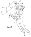
- FIG. 2 is a side view of the adjustable brake pedal assembly of FIG. 1 showing the range of adjustment, according to the present invention.
- FIG. 3 is a perspective view of an adjustable pedal assembly for accelerating, according to the present invention.
- FIG. 4 is a side view of the adjustable accelerator pedal assembly of FIG. 3 showing the range of adjustment, according to the present invention.
- FIG. 5 is a front view of the adjustable accelerator pedal assembly of FIG. 3, according to the present invention.
- Vehicles including a motor vehicle (not shown) utilize foot-actuated devices, referred to as pedals, to control a particular function of the vehicle, such as accelerating, braking and shifting.
- pedals are referred to in the art as an accelerator pedal, brake pedal and clutch pedal.
- the pedals are aligned in a predetermined manner relative to each other, and fixed portions of the vehicle, including the vehicle dash panel, floor, seat and instrument panel.
- the pedal assembly travels in a predetermined path, which in the past was an arc.
- An adjustable pedal assembly includes a pedal pad disposed on an arm. The arm is supported by a bracket, and the bracket is mounted to a portion of the vehicle.
- the adjustable pedal assembly also includes an actuating mechanism for controlling the position of the pedal pad.
- the brake pedal assembly 10 for translating a signal between a vehicle operator or driver (not shown) and a brake actuating mechanism (not shown), as is known in the art for slowing down the vehicle, is illustrated.
- the brake pedal assembly 10 includes a support bracket 12 for attaching the brake pedal assembly 10 to a portion of the vehicle, such as the dash panel.
- the support bracket 12 includes a generally planar mounting surface 14 having apertures 16 for attaching the support bracket 12 to the vehicle, such as by bolting.
- the support bracket 12 includes a channel-shaped support arm 18 extending outwardly from the mounting surface 14 .
- An outer end 20 of the support arm includes at least one, and preferably two apertures 22 for pivotally attaching an adjustment bracket 24 , in a manner to be described.
- the adjustment bracket 24 supports a pedal arm 26 and includes a pair of generally planar sides 28 that are spaced a predetermined distance apart. An upper end of each side 28 includes an upper aperture (not shown) for forming a pedal travel pivot point shown at 30 . It should be appreciated that the brake pedal assembly 10 travels between a resting position and a fully extended position to operatively control a braking mechanism (not shown) for the vehicle.
- a pivot pin 32 is disposed within the support arm aperture 22 and adjustment bracket upper aperture, pivotally interconnecting the support bracket 12 and adjustment bracket 24 , such that the adjustment bracket 24 pivots about the support bracket 12 , which is fixed at the pedal travel pivot point 30 .
- the end of the pivot pin 32 may include a fastener, such as a nut 36 , for retaining the pivot pin 32 .
- the brake pedal assembly includes a torsion spring 34 operatively disposed on the pivot pin 32 for controlling the movement of the brake pedal assembly 10 between a resting and braking position, as is known in the art.
- each adjustment bracket side 28 includes an aperture 38 at a pedal pad pivot point shown at 40 , for ergonomically adjusting the position of a pedal pad 42 relative to a portion of the vehicle such as the floor, or the driver, in a manner to be described.
- Each side 28 further includes a first slot 44 and a second slot 46 for adjusting the position of the pedal pad 42 , in a manner to be described.
- the first slot 44 and second slot 46 have an arcuate shape. It should be appreciated that the first slot 44 and second slot 46 are positioned in a predetermined manner to control the relative position of the pedal pad 42 with respect to the pedal arm 26 , in a manner to be described.
- the pedal pad 42 is attached to a lower end of the pedal arm 26 .
- the pedal arm 26 has an “L” shape and is generally planar; however, it is contemplated that the pedal arm 26 can be formed as a channel.
- the pedal pad 42 is a generally planar member that is rectangular.
- the pedal pad 42 is made from an isomeric material, such as rubber.
- the pedal pad 42 is attached to the pedal arm 26 in a conventional manner, and can be stationary or articulate, as is known in the art.
- the brake pedal assembly 10 includes a pair of generally planar joining members 48 spaced a predetermined distance apart for pivotally interconnecting the adjustment bracket 24 to the pedal arm 26 .
- One end of the joining member includes an aperture 50 for pivotally attaching the adjustment bracket 24 at the pedal pad adjustment pivot point 40 using a conventional attaching mechanism, such as a pivot pin 52 passing through the aperture 38 in the side 28 and the aperture 50 in the one end of the joining member 48 .
- the joining members are positioned between the attachment bracket sides 28 .
- each joining member 48 also includes an aperture 54 , for pivotally attaching the pedal arm 26 to the adjustment bracket 24 .
- An upper end of the pedal arm 26 includes an aperture 58 and is disposed in the space separating the joining members 48 , and is pivotally attached to the other end of each joining member 48 .
- a pivot pin 56 is disposed in the aperture 54 in the other end of the joining member 48 and aperture 58 the upper end of the pedal arm 26 .
- the pivot pin 56 is of sufficient length to extend outwardly, and slidably fit within the first slot 44 in the side 28 , to guide the travel of the pedal arm 26 as the position of the pedal pad 42 is adjusted.
- the pedal arm 26 further includes a perpendicularly extending second pin 60 which slidably fits within the second slot 46 in the side 28 , to further guide the travel of the pedal arm 26 as the position of the pedal pad 42 is adjusted.
- the first and second slots 44 , 46 with first and second pins 56 , 60 slidably traveling therein provides a redundancy to the adjustable brake pedal assembly 10 .
- the adjustable brake pedal assembly 10 also includes a pedal adjusting mechanism 62 .
- the pedal adjusting mechanism includes a jack screw 64 and drive mechanism 66 , which is mounted to the adjustment bracket 24 .
- the jack screw 64 is attached to the pedal arm, such as by a clevis 68 .
- the jack screw 64 extends between the sides 28 of the adjustment bracket 24 .
- An electric motor (not shown) is connected to a worm by a cable, as is known in the art.
- actuation of the pedal adjusting mechanism 62 by the driver induces a lead screw (not shown) to rotate and extend or return the jack screw 64 as shown in FIG. 2.
- the pins 56 , 60 slidably move within the arcuate slots 44 , 46 in the sides 28 of the adjustment bracket 24 , to guide the pedal arm 26 and joining members 48 during adjustment.
- the pedal pad 42 is ergonomically positioned for the driver as shown at 80 .
- adjustable brake pedal assembly 10 may include other component parts, such as switches (not shown), which are conventional and known in the art for the adjustable brake pedal assembly 10 .
- the adjustable accelerator pedal assembly 100 is illustrated. It should be appreciated that the adjustable accelerator pedal assembly 100 is similar to the adjustable brake pedal assembly 10 , and like numerals increased by one hundred are utilized to indicate like components.
- the accelerator pedal assembly 100 includes a support bracket (not shown) for attaching the accelerator pedal assembly 100 to a portion of the vehicle (not shown), such as the dash panel in a conventional manner.
- the accelerator pedal assembly 100 includes an adjustment bracket 124 for supporting a pedal arm 126 .
- the adjustment bracket 124 is a channel shaped member, generally having a backwards C” shape.
- An upper end of the adjustment bracket includes a pair of outwardly extending side portions 128 spaced a predetermined distance apart. Each side portion 128 includes a vertically extending arcuate slot 144 , for a purpose to be described.
- the accelerator pedal assembly 100 includes a pedal arm 126 , with a pedal pad 142 attached to the pedal arm 126 .
- the pedal arm 126 has an “L” shape and is formed as a channel.
- the pedal pad 142 is a generally planar member that is rectangular.
- the pedal pad 142 is made from an isomeric material, such as rubber.
- the pedal pad 142 is attached to the pedal arm 126 in a conventional manner, and can be stationary or articulate, as is known in the art.
- An upper end of the pedal arm 126 includes an aperture 158 for pivotally attaching the pedal arm 126 to the adjustment bracket 124 , in a manner to be described.
- the pedal arm 126 is positioned between the sides 128 of the adjustment bracket 124 .
- the adjustable accelerator pedal assembly 100 includes a pivot pin 170 for attaching the pedal arm 126 to the adjustment bracket 124 .
- the pin 170 is of sufficient length, so that an end of the pin 170 extends therethrough the slot 144 in the adjustment bracket 124 and the aperture 158 in the pedal arm 126 , to slidably attach the pedal arm 126 to the adjustment bracket 124 .
- the end of the pivot pin is elongated as shown at 172 , so that the pin 170 is slidably retained in the arcuate slot 144 of the adjustment bracket 124 .
- the slidable motion of the pin 170 within the arcuate slot 144 guides the travel of the pedal arm 126 in ergonomically adjusting the position of the pedal pad 142 .
- the adjustable accelerator pedal assembly 100 also includes a pedal adjusting mechanism 162 .
- the pedal adjusting mechanism 162 includes a cylindrical worm 174 that drives a gear (not shown) mounted on a lead screw 176 , as is known in the art.
- the worm 174 is mounted to a lower end of the adjustment bracket 124 .
- the worm 174 is turned by a motor (not shown) which is mounted in a remote location and connected to the center of the worm gear 174 by a cable 178 .
- the screw end extends outwardly to the lead screw 176 supporting a trunion (not shown), to which a lower portion of the pedal arm 126 is pivotally connected.
- Energization of the motor drives the cable 178 to turn the worm 174 and worm gear to move the lead screw 176 with the trunion.
- the pedal arm 126 is moved away from the adjustment bracket 124 and the pin 170 slides downwardly in the arcuate slot 144 to move the pedal pad 142 rearwardly into the vehicle and upwardly from the floor as shown at 180 in FIG. 4.
- the pedal arm 126 is free to rotate about the trunion attached to the lead screw 176 as the pedal arm 126 is adjusted.
- the curvature of the slot 144 in the adjustment bracket 124 is determined in combination with the attachment of the pedal pad 142 and pedal pad length, to permit repositioning of the pedal pad 142 at a predetermined angle with respect to the floor, after the position of the pedal arm 126 has been adjusted.
- the center of the radius of curvature is positioned rearwardly of the adjustment bracket 124 and above the pedal arm 126 and surface.
- the pedal pad 142 has an elongated curved shape.
- the angle of the foot in contacting the pedal pad 142 is ergonomically maintained while the height of the pedal pad 142 with respect to the floor of the vehicle is adjusted to a comfortable position for the driver.
- adjustable accelerator pedal assembly 100 may include other component parts, such as switches (not shown), which are conventional and known in the art for the adjustable accelerator pedal assembly.
Abstract
Description
- This application claims priority of U.S. Provisional Patent Application No. 60/212,108 filed Jun. 15, 2000, and U.S. patent application Ser. No. 09/882,981, filed Jun. 15, 2001 and entitled: “Adjustable Pedal Assembly” and is incorporated herein by reference.
- This invention relates to pedals, and more particularly to an adjustable pedal assembly for a vehicle.
- Vehicles, such as motor vehicles, typically contain foot-actuated devices or pedals for controlling various functions of the vehicle. These functions are known to include acceleration, controlled by an accelerator pedal; braking controlled by a brake pedal; and shifting controlled by a clutch pedal. These pedals are positioned in the vehicle so that they are accessible by the driver. However, drivers come in a wide variety of shapes and sizes, and a pedal positioned to accommodate a large driver with a large foot will generally be unreachable by a small driver with a small foot. In the past, the pedals were fixedly positioned to accommodate the majority of drivers, from a functional and ergonomic perspective. The functionality of the pedal relates to the ability of the driver to reach and actuate the pedal. Another functional factor is clearance between pedals. The ergonomics of the pedal relates to factors such as the driver's comfort while actuating the pedal, as measured by foot angle. Another example of an ergonomic factor is foot fatigue from maintaining the foot in a fixed position for a period of time.
- More recently, adjustable pedals have been used in vehicles to accommodate a greater number of drivers. The driver can modify the position of the pedal relative to the floor of the vehicle. An example of such an adjustable pedal is disclosed in commonly assigned U.S. Pat. No. 6,151,986 to KSR Industrial Corporation entitled “Adjustable Vehicle Control Pedals,” the disclosure of which is incorporated herein by reference. While this type of adjustable pedal works by adjusting the relative position of the pedal along a predetermined arc of travel, after the pedal position has been adjusted, the pedal pad may not be aligned ergonomically with respect to the foot of the operator. Thus, there is a need in the art for an ergonomically beneficial adjustable pedal assembly that adjusts the position of both the pedal and pedal pad.
- Accordingly, the present invention is an adjustable pedal assembly. The adjustable pedal assembly includes an adjustment bracket adapted for mounting on a vehicle, and the adjustment bracket includes a pair of outwardly extending side portions having a vertically extending arcuate slot. The adjustable pedal assembly also includes a pedal arm pivotally attached to the adjustment bracket using a pivot pin, such that an end of the pivot pin is slidably disposed within the arcuate slot in the adjustment bracket. The adjustable pedal assembly further includes a pedal pad mounted to the pedal arm, and a pedal adjustment mechanism operatively attached to the pedal arm, for adjusting the position of the pedal arm along a predetermined path, such that the pivot pin is slidably positioned in the arcuate slot relative to the predetermined path of the pedal arm to ergonomically position the pedal pad.
- One advantage of the present invention is that an adjustable pedal assembly is provided that is ergonomically positioned with respect to the foot of the driver. Another advantage of the present invention is that an adjustable pedal assembly is provided whereby the angle of the pedal pad with respect to the floor of the vehicle is automatically aligned as the position of the pedal assembly is adjusted. A further advantage of the present invention is that an adjustable pedal assembly is provided that is more comfortable for the driver while operating the vehicle. Still a further advantage of the present invention is that an adjustable pedal assembly is provided that ergonomically positions the pedal pad to improve the feel of the pedal assembly by the driver.
- Other features and advantages of the present invention will be readily understood as the same becomes better understood after reading the subsequent description when considered in connection with the accompanying drawings.
- FIG. 1 is a perspective view of an adjustable pedal assembly for braking, according to the present invention.
- FIG. 2 is a side view of the adjustable brake pedal assembly of FIG. 1 showing the range of adjustment, according to the present invention.
- FIG. 3 is a perspective view of an adjustable pedal assembly for accelerating, according to the present invention.
- FIG. 4 is a side view of the adjustable accelerator pedal assembly of FIG. 3 showing the range of adjustment, according to the present invention.
- FIG. 5 is a front view of the adjustable accelerator pedal assembly of FIG. 3, according to the present invention.
- Vehicles, including a motor vehicle (not shown) utilize foot-actuated devices, referred to as pedals, to control a particular function of the vehicle, such as accelerating, braking and shifting. These pedals are referred to in the art as an accelerator pedal, brake pedal and clutch pedal. The pedals are aligned in a predetermined manner relative to each other, and fixed portions of the vehicle, including the vehicle dash panel, floor, seat and instrument panel. The pedal assembly travels in a predetermined path, which in the past was an arc. Thus, to increase the height of the pedal pad (to be described) with respect to the floor, the pedal pad moves rearward along an arc, or into the vehicle. An adjustable pedal assembly includes a pedal pad disposed on an arm. The arm is supported by a bracket, and the bracket is mounted to a portion of the vehicle. The adjustable pedal assembly also includes an actuating mechanism for controlling the position of the pedal pad.
- Referring to FIGS. 1 and 2, an adjustable
brake pedal assembly 10 for translating a signal between a vehicle operator or driver (not shown) and a brake actuating mechanism (not shown), as is known in the art for slowing down the vehicle, is illustrated. Thebrake pedal assembly 10 includes asupport bracket 12 for attaching thebrake pedal assembly 10 to a portion of the vehicle, such as the dash panel. In this example, thesupport bracket 12 includes a generallyplanar mounting surface 14 havingapertures 16 for attaching thesupport bracket 12 to the vehicle, such as by bolting. Thesupport bracket 12 includes a channel-shaped support arm 18 extending outwardly from themounting surface 14. Anouter end 20 of the support arm includes at least one, and preferably twoapertures 22 for pivotally attaching anadjustment bracket 24, in a manner to be described. - The
adjustment bracket 24 supports apedal arm 26 and includes a pair of generallyplanar sides 28 that are spaced a predetermined distance apart. An upper end of eachside 28 includes an upper aperture (not shown) for forming a pedal travel pivot point shown at 30. It should be appreciated that thebrake pedal assembly 10 travels between a resting position and a fully extended position to operatively control a braking mechanism (not shown) for the vehicle. Apivot pin 32 is disposed within thesupport arm aperture 22 and adjustment bracket upper aperture, pivotally interconnecting thesupport bracket 12 andadjustment bracket 24, such that theadjustment bracket 24 pivots about thesupport bracket 12, which is fixed at the pedaltravel pivot point 30. It should be appreciated that the end of thepivot pin 32 may include a fastener, such as anut 36, for retaining thepivot pin 32. Preferably, the brake pedal assembly includes atorsion spring 34 operatively disposed on thepivot pin 32 for controlling the movement of thebrake pedal assembly 10 between a resting and braking position, as is known in the art. - An outer end of each
adjustment bracket side 28 includes anaperture 38 at a pedal pad pivot point shown at 40, for ergonomically adjusting the position of apedal pad 42 relative to a portion of the vehicle such as the floor, or the driver, in a manner to be described. Eachside 28 further includes afirst slot 44 and asecond slot 46 for adjusting the position of thepedal pad 42, in a manner to be described. In this example, thefirst slot 44 andsecond slot 46 have an arcuate shape. It should be appreciated that thefirst slot 44 andsecond slot 46 are positioned in a predetermined manner to control the relative position of thepedal pad 42 with respect to thepedal arm 26, in a manner to be described. - The
pedal pad 42 is attached to a lower end of thepedal arm 26. In this example, thepedal arm 26 has an “L” shape and is generally planar; however, it is contemplated that thepedal arm 26 can be formed as a channel. Thepedal pad 42 is a generally planar member that is rectangular. Preferably, thepedal pad 42 is made from an isomeric material, such as rubber. Thepedal pad 42 is attached to thepedal arm 26 in a conventional manner, and can be stationary or articulate, as is known in the art. - The
brake pedal assembly 10 includes a pair of generally planar joiningmembers 48 spaced a predetermined distance apart for pivotally interconnecting theadjustment bracket 24 to thepedal arm 26. One end of the joining member includes anaperture 50 for pivotally attaching theadjustment bracket 24 at the pedal padadjustment pivot point 40 using a conventional attaching mechanism, such as apivot pin 52 passing through theaperture 38 in theside 28 and theaperture 50 in the one end of the joiningmember 48. In this example, the joining members are positioned between the attachment bracket sides 28. - Another end of each joining
member 48 also includes anaperture 54, for pivotally attaching thepedal arm 26 to theadjustment bracket 24. An upper end of thepedal arm 26 includes anaperture 58 and is disposed in the space separating the joiningmembers 48, and is pivotally attached to the other end of each joiningmember 48. For example, apivot pin 56 is disposed in theaperture 54 in the other end of the joiningmember 48 andaperture 58 the upper end of thepedal arm 26. Preferably, thepivot pin 56 is of sufficient length to extend outwardly, and slidably fit within thefirst slot 44 in theside 28, to guide the travel of thepedal arm 26 as the position of thepedal pad 42 is adjusted. Thepedal arm 26 further includes a perpendicularly extendingsecond pin 60 which slidably fits within thesecond slot 46 in theside 28, to further guide the travel of thepedal arm 26 as the position of thepedal pad 42 is adjusted. Advantageously, the first andsecond slots second pins brake pedal assembly 10. - The adjustable
brake pedal assembly 10 also includes apedal adjusting mechanism 62. In this example, the pedal adjusting mechanism includes ajack screw 64 anddrive mechanism 66, which is mounted to theadjustment bracket 24. Preferably, thejack screw 64 is attached to the pedal arm, such as by aclevis 68. Thejack screw 64 extends between thesides 28 of theadjustment bracket 24. An electric motor (not shown) is connected to a worm by a cable, as is known in the art. - In operation, actuation of the
pedal adjusting mechanism 62 by the driver (not shown) induces a lead screw (not shown) to rotate and extend or return thejack screw 64 as shown in FIG. 2. Thepins arcuate slots sides 28 of theadjustment bracket 24, to guide thepedal arm 26 and joiningmembers 48 during adjustment. As thepedal arm 26 is adjusted, thepedal pad 42 is ergonomically positioned for the driver as shown at 80. - It should be appreciated that the adjustable
brake pedal assembly 10 may include other component parts, such as switches (not shown), which are conventional and known in the art for the adjustablebrake pedal assembly 10. - Referring to FIGS. 3-5, the adjustable
accelerator pedal assembly 100 is illustrated. It should be appreciated that the adjustableaccelerator pedal assembly 100 is similar to the adjustablebrake pedal assembly 10, and like numerals increased by one hundred are utilized to indicate like components. - The
accelerator pedal assembly 100 includes a support bracket (not shown) for attaching theaccelerator pedal assembly 100 to a portion of the vehicle (not shown), such as the dash panel in a conventional manner. Theaccelerator pedal assembly 100 includes anadjustment bracket 124 for supporting apedal arm 126. Theadjustment bracket 124 is a channel shaped member, generally having a backwards C” shape. An upper end of the adjustment bracket includes a pair of outwardly extendingside portions 128 spaced a predetermined distance apart. Eachside portion 128 includes a vertically extendingarcuate slot 144, for a purpose to be described. - The
accelerator pedal assembly 100 includes apedal arm 126, with apedal pad 142 attached to thepedal arm 126. In this example, thepedal arm 126 has an “L” shape and is formed as a channel. Thepedal pad 142 is a generally planar member that is rectangular. Preferably, thepedal pad 142 is made from an isomeric material, such as rubber. Thepedal pad 142 is attached to thepedal arm 126 in a conventional manner, and can be stationary or articulate, as is known in the art. An upper end of thepedal arm 126 includes anaperture 158 for pivotally attaching thepedal arm 126 to theadjustment bracket 124, in a manner to be described. In this example, thepedal arm 126 is positioned between thesides 128 of theadjustment bracket 124. - The adjustable
accelerator pedal assembly 100 includes apivot pin 170 for attaching thepedal arm 126 to theadjustment bracket 124. Thepin 170 is of sufficient length, so that an end of thepin 170 extends therethrough theslot 144 in theadjustment bracket 124 and theaperture 158 in thepedal arm 126, to slidably attach thepedal arm 126 to theadjustment bracket 124. Preferably, the end of the pivot pin is elongated as shown at 172, so that thepin 170 is slidably retained in thearcuate slot 144 of theadjustment bracket 124. Advantageously, the slidable motion of thepin 170 within thearcuate slot 144 guides the travel of thepedal arm 126 in ergonomically adjusting the position of thepedal pad 142. - The adjustable
accelerator pedal assembly 100 also includes apedal adjusting mechanism 162. For example, thepedal adjusting mechanism 162 includes acylindrical worm 174 that drives a gear (not shown) mounted on alead screw 176, as is known in the art. Theworm 174 is mounted to a lower end of theadjustment bracket 124. Theworm 174 is turned by a motor (not shown) which is mounted in a remote location and connected to the center of theworm gear 174 by acable 178. The screw end extends outwardly to thelead screw 176 supporting a trunion (not shown), to which a lower portion of thepedal arm 126 is pivotally connected. Energization of the motor drives thecable 178 to turn theworm 174 and worm gear to move thelead screw 176 with the trunion. As the trunion moves outwardly on thelead screw 176, thepedal arm 126 is moved away from theadjustment bracket 124 and thepin 170 slides downwardly in thearcuate slot 144 to move thepedal pad 142 rearwardly into the vehicle and upwardly from the floor as shown at 180 in FIG. 4. Thepedal arm 126 is free to rotate about the trunion attached to thelead screw 176 as thepedal arm 126 is adjusted. - Advantageously, the curvature of the
slot 144 in theadjustment bracket 124 is determined in combination with the attachment of thepedal pad 142 and pedal pad length, to permit repositioning of thepedal pad 142 at a predetermined angle with respect to the floor, after the position of thepedal arm 126 has been adjusted. The center of the radius of curvature is positioned rearwardly of theadjustment bracket 124 and above thepedal arm 126 and surface. It should be appreciated that in this example, thepedal pad 142 has an elongated curved shape. Advantageously, the angle of the foot in contacting thepedal pad 142 is ergonomically maintained while the height of thepedal pad 142 with respect to the floor of the vehicle is adjusted to a comfortable position for the driver. - It should be appreciated that the adjustable
accelerator pedal assembly 100 may include other component parts, such as switches (not shown), which are conventional and known in the art for the adjustable accelerator pedal assembly. - The present invention has been described in an illustrative manner. It is to be understood that the terminology which has been used is intended to be in the nature of words of description rather than of limitation. Many modifications and variations of the present invention are possible in light of the above teachings. Therefore, within the scope of the appended claims, the present invention may be practiced other than as specifically described.
Claims (8)
Priority Applications (1)
| Application Number | Priority Date | Filing Date | Title |
|---|---|---|---|
| US10/447,127 US7051613B2 (en) | 2000-06-15 | 2003-05-28 | Adjustable pedal assembly |
Applications Claiming Priority (3)
| Application Number | Priority Date | Filing Date | Title |
|---|---|---|---|
| US21210800P | 2000-06-15 | 2000-06-15 | |
| US09/882,981 US6584871B2 (en) | 2000-06-15 | 2001-06-15 | Adjustable pedal assembly |
| US10/447,127 US7051613B2 (en) | 2000-06-15 | 2003-05-28 | Adjustable pedal assembly |
Related Parent Applications (1)
| Application Number | Title | Priority Date | Filing Date |
|---|---|---|---|
| US09/882,981 Continuation US6584871B2 (en) | 2000-06-15 | 2001-06-15 | Adjustable pedal assembly |
Publications (2)
| Publication Number | Publication Date |
|---|---|
| US20030192394A1 true US20030192394A1 (en) | 2003-10-16 |
| US7051613B2 US7051613B2 (en) | 2006-05-30 |
Family
ID=26906776
Family Applications (2)
| Application Number | Title | Priority Date | Filing Date |
|---|---|---|---|
| US09/882,981 Expired - Fee Related US6584871B2 (en) | 2000-06-15 | 2001-06-15 | Adjustable pedal assembly |
| US10/447,127 Expired - Fee Related US7051613B2 (en) | 2000-06-15 | 2003-05-28 | Adjustable pedal assembly |
Family Applications Before (1)
| Application Number | Title | Priority Date | Filing Date |
|---|---|---|---|
| US09/882,981 Expired - Fee Related US6584871B2 (en) | 2000-06-15 | 2001-06-15 | Adjustable pedal assembly |
Country Status (1)
| Country | Link |
|---|---|
| US (2) | US6584871B2 (en) |
Cited By (2)
| Publication number | Priority date | Publication date | Assignee | Title |
|---|---|---|---|---|
| US20100107804A1 (en) * | 2008-11-04 | 2010-05-06 | Tervol Stuart A | Fixed pedal assembly with multi-piece support bracket and captive pivot |
| CN105730558A (en) * | 2016-02-02 | 2016-07-06 | 北京汽车股份有限公司 | Automobile pedal man-machine operating space determining device |
Families Citing this family (36)
| Publication number | Priority date | Publication date | Assignee | Title |
|---|---|---|---|---|
| US6564672B2 (en) * | 2000-05-15 | 2003-05-20 | Grand Haven Stamped Products, Division Of Jsj Corporation | Adjustable pedal apparatus |
| US6619155B2 (en) | 2000-05-15 | 2003-09-16 | Grand Haven Stamped Products, Division Of Jsj Corporation | Adjustable pedal apparatus |
| US6584871B2 (en) * | 2000-06-15 | 2003-07-01 | Ksr International, Inc. | Adjustable pedal assembly |
| JP3964618B2 (en) * | 2000-12-22 | 2007-08-22 | 豊田鉄工株式会社 | Front and rear adjustable pedal device for vehicles |
| FR2821177B1 (en) * | 2001-02-19 | 2003-04-25 | Peugeot Citroen Automobiles Sa | CLUTCH PEDAL FOR EQUIPPING A VEHICLE |
| FR2821178B1 (en) * | 2001-02-19 | 2003-04-25 | Peugeot Citroen Automobiles Sa | BRAKE PEDAL FOR FITTING A MOTOR VEHICLE |
| FR2821179B1 (en) * | 2001-02-19 | 2003-04-25 | Peugeot Citroen Automobiles Sa | FOOTREST FOR MOTOR VEHICLE |
| US7114411B2 (en) * | 2001-05-09 | 2006-10-03 | Ksr Industrial Corporation | Pedal adjuster |
| US7146876B2 (en) * | 2002-06-28 | 2006-12-12 | Ksr International Company | Adjustable pedal assembly |
| JP4138404B2 (en) | 2002-08-27 | 2008-08-27 | 豊田鉄工株式会社 | Movable pedal device |
| JP3942990B2 (en) * | 2002-08-27 | 2007-07-11 | 豊田鉄工株式会社 | Movable pedal device |
| DE10254586B4 (en) * | 2002-11-22 | 2006-12-28 | Fico Cables, S.A., Rubi | Mechanism for adjusting the lever ratio of an actuating lever |
| DE10254585A1 (en) * | 2002-11-22 | 2004-06-09 | Fico Cables, S.A., Rubi | Adjustable position pedal |
| US7823480B2 (en) * | 2003-07-03 | 2010-11-02 | Ksr Technologies Co. | Support bracket with an integrated switch for a pedal assembly |
| US7219576B2 (en) * | 2003-11-26 | 2007-05-22 | Ventra Group Inc. | Variable ratio pedal assembly |
| US7530289B2 (en) * | 2004-01-23 | 2009-05-12 | Ksr Technologies Co. | Manual adjustable pedal assembly |
| CZ302239B6 (en) * | 2004-03-16 | 2011-01-05 | Brano A.S. | Adjustable pedal mechanism |
| US7832305B2 (en) * | 2005-10-31 | 2010-11-16 | Dura Global Technologies Llc | Adjustable pedal system with low brake ratio change |
| KR100649166B1 (en) * | 2005-11-09 | 2006-11-27 | 에스엘 주식회사 | Adjustable pedal system |
| US7775613B2 (en) * | 2006-03-06 | 2010-08-17 | Intier Automotive Inc. | Storage assembly |
| JP4658861B2 (en) * | 2006-05-30 | 2011-03-23 | 本田技研工業株式会社 | Link-type front and rear position variable pedal device |
| FR2902395B1 (en) * | 2006-06-20 | 2009-02-06 | Peugeot Citroen Automobiles Sa | KIT FOR ASSEMBLING A BRAKE PEDAL WITH A PEDAL EQUIPPED WITH A MOTOR VEHICLE, BRAKE PEDAL, AND CONNECTION METHOD |
| US20080073959A1 (en) * | 2006-08-24 | 2008-03-27 | Sergey Anikin | Device for shortening brake activation reaction time |
| US8069750B2 (en) | 2007-08-09 | 2011-12-06 | Ksr Technologies Co. | Compact pedal assembly with improved noise control |
| US7730806B1 (en) | 2007-10-29 | 2010-06-08 | Stanzie Grimaldi | Vehicle pedal booster and associated method |
| CN101698384A (en) * | 2009-11-06 | 2010-04-28 | 奇瑞汽车股份有限公司 | Adjustable pedal assembly and multi-degree-of-freedom combined pedal system using same |
| DE102009059000B4 (en) * | 2009-12-17 | 2011-12-08 | Autoliv Development Ab | Pedal arrangement for a motor vehicle |
| US8508242B2 (en) * | 2010-01-25 | 2013-08-13 | Ksr Technologies Co. | Inductive position sensor |
| US20150107401A1 (en) * | 2013-10-23 | 2015-04-23 | The U.S.A. As Represented By The Administrator Of The National Aeronautics And Space Administration | Pedal module for a vehicle having a control-by-wire system |
| ITTO20130902A1 (en) * | 2013-11-06 | 2015-05-07 | Fiat Group Automobiles Spa | MANUAL LEVER DEVICE FOR DRIVING THE BRAKE OF A MOTOR VEHICLE |
| US20150135892A1 (en) * | 2013-11-18 | 2015-05-21 | KSR IP Holdings, LLC | Adjustable pedal assembly |
| CN103655075A (en) * | 2014-01-04 | 2014-03-26 | 李健 | Wheelchair pedal regulator |
| DE102014206386A1 (en) | 2014-04-03 | 2015-10-08 | Boge Elastmetall Gmbh | Pedal body for an actuating pedal of a motor vehicle |
| EP3206921B1 (en) * | 2014-10-15 | 2019-08-21 | Ventra Group Co. | Variable ratio mechanism for adjustable pedals to maintain a constant ratio |
| US11155163B2 (en) * | 2017-05-04 | 2021-10-26 | Volvo Truck Corporation | Method for assembling a clutch control unit in a transmission clutch housing |
| KR20210102654A (en) * | 2020-02-12 | 2021-08-20 | 현대자동차주식회사 | Foldable brake pedal apparatus for autonomous driving vehicle |
Citations (46)
| Publication number | Priority date | Publication date | Assignee | Title |
|---|---|---|---|---|
| US2860720A (en) * | 1956-01-18 | 1958-11-18 | Gen Motors Corp | Adjustable toeboard for an automobile |
| US2906842A (en) * | 1958-03-20 | 1959-09-29 | Electro Snap Switch & Mfg Co | Adjustable actuator arm |
| US2908183A (en) * | 1953-04-21 | 1959-10-13 | Giovanni Norman P Di | Accelerator foot control and adjustment mechanisms |
| US2936867A (en) * | 1959-02-17 | 1960-05-17 | Nelson I Perry | Combined accelerator and foot brake |
| US3301088A (en) * | 1964-03-02 | 1967-01-31 | Gen Motors Corp | Vehicle adjustable control pedal assemblies |
| US3319487A (en) * | 1964-01-09 | 1967-05-16 | Gen Motors Corp | Vehicle control pedals |
| US3338348A (en) * | 1964-09-15 | 1967-08-29 | Gen Motors Corp | Brake pedal height adjusting and ratio changing mechanism |
| US3400607A (en) * | 1965-12-20 | 1968-09-10 | Ford Motor Co | Vehicle control assembly |
| US3511109A (en) * | 1968-10-14 | 1970-05-12 | Gen Motors Corp | Adjustable control pedals |
| US3643524A (en) * | 1970-05-26 | 1972-02-22 | Gen Motors Corp | Control pedals for vehicles |
| US3691868A (en) * | 1971-07-06 | 1972-09-19 | Raymond P Smith | Adjustable pedal |
| US3754480A (en) * | 1972-05-08 | 1973-08-28 | Gen Motors Corp | Vehicle control apparatus |
| US3765264A (en) * | 1971-11-19 | 1973-10-16 | Grand Stamped Prod Co | Adjustable linkage |
| US3798995A (en) * | 1972-11-09 | 1974-03-26 | H Schroter | Brake operating lever system |
| US3828625A (en) * | 1971-11-19 | 1974-08-13 | Grand Haven Stamped Prod | Adjustable linkage |
| US3958677A (en) * | 1974-09-18 | 1976-05-25 | Spanelis Evangelos L | Unitary pedal apparatus for selectively accelerating and braking a vehicle |
| US3975972A (en) * | 1975-04-16 | 1976-08-24 | Muhleck Earl M | Adjustable pedal construction |
| US4497399A (en) * | 1982-12-03 | 1985-02-05 | General Motors Corporation | Adjusting mechanism for a manually operated clutch |
| US4683977A (en) * | 1985-05-15 | 1987-08-04 | Thomas Murphy | Adjustable pedal assembly |
| US4870871A (en) * | 1987-05-22 | 1989-10-03 | Wickes Manufacturing Company | Adjustable accelerator and brake pedal mechanism |
| US4875385A (en) * | 1986-08-18 | 1989-10-24 | Sitrin Gabriel M | Control pedal apparatus for a motor vehicle |
| US4912997A (en) * | 1989-06-02 | 1990-04-03 | Chrysler Corporation | Electric shift selector mechanism for transmission |
| US4989474A (en) * | 1986-08-18 | 1991-02-05 | Brecom Corporation | Control pedal apparatus for a motor vehicle |
| US5010782A (en) * | 1988-07-28 | 1991-04-30 | Fuji Kiko Company, Ltd. | Position adjustable pedal assembly |
| US5078024A (en) * | 1986-08-18 | 1992-01-07 | Comfort Pedals Inc. | Control pedal apparatus for a motor vehicle |
| US5086663A (en) * | 1989-07-28 | 1992-02-11 | Fuji Kiko Company, Limited | Adjustable pedal |
| US5172606A (en) * | 1992-03-25 | 1992-12-22 | General Motors Corporation | Module cockpit/support structure with adjustable pedals |
| US5351573A (en) * | 1991-10-07 | 1994-10-04 | Cicotte Edmond B | Adjustable automobile pedal system |
| US5385068A (en) * | 1992-12-18 | 1995-01-31 | Cts Corporation | Electronic accelerator pedal assembly with pedal force sensor |
| US5408899A (en) * | 1993-06-14 | 1995-04-25 | Brecom Subsidiary Corporation No. 1 | Foot pedal devices for controlling engines |
| US5460061A (en) * | 1993-09-17 | 1995-10-24 | Comfort Pedals, Inc. | Adjustable control pedal apparatus |
| US5497677A (en) * | 1993-12-21 | 1996-03-12 | Dr. Ing. H.C.F. Porsche Ag | Accelerator pedal device for a motor vehicle |
| US5632183A (en) * | 1995-08-09 | 1997-05-27 | Comfort Pedals, Inc. | Adjustable pedal assembly |
| US5772302A (en) * | 1992-03-12 | 1998-06-30 | Asahi Kogaku Kogyo Kabushiki Kaisha | Strobe device |
| US5771752A (en) * | 1991-10-07 | 1998-06-30 | Cicotte; Edmond B. | Adjustable automobile pedal system |
| US5819593A (en) * | 1995-08-09 | 1998-10-13 | Comcorp Technologies, Inc. | Electronic adjustable pedal assembly |
| US5996438A (en) * | 1998-06-23 | 1999-12-07 | General Motors Corporation | Adjustable accelerator pedal |
| US6019015A (en) * | 1998-02-11 | 2000-02-01 | General Motors Corporation | Adjustable accelerator pedal |
| US6073515A (en) * | 1998-07-21 | 2000-06-13 | General Motors Corporation | Adjustable foot support |
| US6151985A (en) * | 1999-04-01 | 2000-11-28 | Daimlerchrysler Corporation | Adjustable pedal apparatus |
| US6289761B1 (en) * | 2000-02-04 | 2001-09-18 | Dura Global Technologies, Inc. | Automatic adjustable brake, clutch and accelerator pedals |
| US6321617B1 (en) * | 2000-06-08 | 2001-11-27 | Jeffrey Schwyn | Adjustable pedal assembly |
| US6367349B1 (en) * | 2000-05-01 | 2002-04-09 | Dura Global Technologies, Inc. | Adjustable brake, clutch and accelerator pedals |
| US6367348B1 (en) * | 2000-05-01 | 2002-04-09 | Dura Global Technologies, Inc. | Adjustable brake, clutch and accelerator pedals |
| US6584871B2 (en) * | 2000-06-15 | 2003-07-01 | Ksr International, Inc. | Adjustable pedal assembly |
| US6662677B2 (en) * | 1999-10-15 | 2003-12-16 | Teleflex Incorporated | Adjustable pedal assembly (banana rod) |
Family Cites Families (4)
| Publication number | Priority date | Publication date | Assignee | Title |
|---|---|---|---|---|
| GB1558185A (en) | 1975-10-03 | 1979-12-19 | Lucas Industries Ltd | Vehicle suspension system |
| US5722302A (en) | 1995-08-09 | 1998-03-03 | Teleflex, Inc. | Adjustable pedal assembly |
| FR2739947B1 (en) | 1995-10-17 | 1997-12-12 | Renault | MOTOR VEHICLE CRANKSET HAVING A DEVICE FOR ADJUSTING THE HEIGHT AND THE ORIENTATION OF THE PEDALS |
| US5996439A (en) | 1998-07-22 | 1999-12-07 | General Motors Corporation | Brake pedal mechanism |
-
2001
- 2001-06-15 US US09/882,981 patent/US6584871B2/en not_active Expired - Fee Related
-
2003
- 2003-05-28 US US10/447,127 patent/US7051613B2/en not_active Expired - Fee Related
Patent Citations (46)
| Publication number | Priority date | Publication date | Assignee | Title |
|---|---|---|---|---|
| US2908183A (en) * | 1953-04-21 | 1959-10-13 | Giovanni Norman P Di | Accelerator foot control and adjustment mechanisms |
| US2860720A (en) * | 1956-01-18 | 1958-11-18 | Gen Motors Corp | Adjustable toeboard for an automobile |
| US2906842A (en) * | 1958-03-20 | 1959-09-29 | Electro Snap Switch & Mfg Co | Adjustable actuator arm |
| US2936867A (en) * | 1959-02-17 | 1960-05-17 | Nelson I Perry | Combined accelerator and foot brake |
| US3319487A (en) * | 1964-01-09 | 1967-05-16 | Gen Motors Corp | Vehicle control pedals |
| US3301088A (en) * | 1964-03-02 | 1967-01-31 | Gen Motors Corp | Vehicle adjustable control pedal assemblies |
| US3338348A (en) * | 1964-09-15 | 1967-08-29 | Gen Motors Corp | Brake pedal height adjusting and ratio changing mechanism |
| US3400607A (en) * | 1965-12-20 | 1968-09-10 | Ford Motor Co | Vehicle control assembly |
| US3511109A (en) * | 1968-10-14 | 1970-05-12 | Gen Motors Corp | Adjustable control pedals |
| US3643524A (en) * | 1970-05-26 | 1972-02-22 | Gen Motors Corp | Control pedals for vehicles |
| US3691868A (en) * | 1971-07-06 | 1972-09-19 | Raymond P Smith | Adjustable pedal |
| US3765264A (en) * | 1971-11-19 | 1973-10-16 | Grand Stamped Prod Co | Adjustable linkage |
| US3828625A (en) * | 1971-11-19 | 1974-08-13 | Grand Haven Stamped Prod | Adjustable linkage |
| US3754480A (en) * | 1972-05-08 | 1973-08-28 | Gen Motors Corp | Vehicle control apparatus |
| US3798995A (en) * | 1972-11-09 | 1974-03-26 | H Schroter | Brake operating lever system |
| US3958677A (en) * | 1974-09-18 | 1976-05-25 | Spanelis Evangelos L | Unitary pedal apparatus for selectively accelerating and braking a vehicle |
| US3975972A (en) * | 1975-04-16 | 1976-08-24 | Muhleck Earl M | Adjustable pedal construction |
| US4497399A (en) * | 1982-12-03 | 1985-02-05 | General Motors Corporation | Adjusting mechanism for a manually operated clutch |
| US4683977A (en) * | 1985-05-15 | 1987-08-04 | Thomas Murphy | Adjustable pedal assembly |
| US4989474A (en) * | 1986-08-18 | 1991-02-05 | Brecom Corporation | Control pedal apparatus for a motor vehicle |
| US4875385A (en) * | 1986-08-18 | 1989-10-24 | Sitrin Gabriel M | Control pedal apparatus for a motor vehicle |
| US5078024A (en) * | 1986-08-18 | 1992-01-07 | Comfort Pedals Inc. | Control pedal apparatus for a motor vehicle |
| US4870871A (en) * | 1987-05-22 | 1989-10-03 | Wickes Manufacturing Company | Adjustable accelerator and brake pedal mechanism |
| US5010782A (en) * | 1988-07-28 | 1991-04-30 | Fuji Kiko Company, Ltd. | Position adjustable pedal assembly |
| US4912997A (en) * | 1989-06-02 | 1990-04-03 | Chrysler Corporation | Electric shift selector mechanism for transmission |
| US5086663A (en) * | 1989-07-28 | 1992-02-11 | Fuji Kiko Company, Limited | Adjustable pedal |
| US5771752A (en) * | 1991-10-07 | 1998-06-30 | Cicotte; Edmond B. | Adjustable automobile pedal system |
| US5351573A (en) * | 1991-10-07 | 1994-10-04 | Cicotte Edmond B | Adjustable automobile pedal system |
| US5772302A (en) * | 1992-03-12 | 1998-06-30 | Asahi Kogaku Kogyo Kabushiki Kaisha | Strobe device |
| US5172606A (en) * | 1992-03-25 | 1992-12-22 | General Motors Corporation | Module cockpit/support structure with adjustable pedals |
| US5385068A (en) * | 1992-12-18 | 1995-01-31 | Cts Corporation | Electronic accelerator pedal assembly with pedal force sensor |
| US5408899A (en) * | 1993-06-14 | 1995-04-25 | Brecom Subsidiary Corporation No. 1 | Foot pedal devices for controlling engines |
| US5460061A (en) * | 1993-09-17 | 1995-10-24 | Comfort Pedals, Inc. | Adjustable control pedal apparatus |
| US5497677A (en) * | 1993-12-21 | 1996-03-12 | Dr. Ing. H.C.F. Porsche Ag | Accelerator pedal device for a motor vehicle |
| US5632183A (en) * | 1995-08-09 | 1997-05-27 | Comfort Pedals, Inc. | Adjustable pedal assembly |
| US5819593A (en) * | 1995-08-09 | 1998-10-13 | Comcorp Technologies, Inc. | Electronic adjustable pedal assembly |
| US6019015A (en) * | 1998-02-11 | 2000-02-01 | General Motors Corporation | Adjustable accelerator pedal |
| US5996438A (en) * | 1998-06-23 | 1999-12-07 | General Motors Corporation | Adjustable accelerator pedal |
| US6073515A (en) * | 1998-07-21 | 2000-06-13 | General Motors Corporation | Adjustable foot support |
| US6151985A (en) * | 1999-04-01 | 2000-11-28 | Daimlerchrysler Corporation | Adjustable pedal apparatus |
| US6662677B2 (en) * | 1999-10-15 | 2003-12-16 | Teleflex Incorporated | Adjustable pedal assembly (banana rod) |
| US6289761B1 (en) * | 2000-02-04 | 2001-09-18 | Dura Global Technologies, Inc. | Automatic adjustable brake, clutch and accelerator pedals |
| US6367349B1 (en) * | 2000-05-01 | 2002-04-09 | Dura Global Technologies, Inc. | Adjustable brake, clutch and accelerator pedals |
| US6367348B1 (en) * | 2000-05-01 | 2002-04-09 | Dura Global Technologies, Inc. | Adjustable brake, clutch and accelerator pedals |
| US6321617B1 (en) * | 2000-06-08 | 2001-11-27 | Jeffrey Schwyn | Adjustable pedal assembly |
| US6584871B2 (en) * | 2000-06-15 | 2003-07-01 | Ksr International, Inc. | Adjustable pedal assembly |
Cited By (3)
| Publication number | Priority date | Publication date | Assignee | Title |
|---|---|---|---|---|
| US20100107804A1 (en) * | 2008-11-04 | 2010-05-06 | Tervol Stuart A | Fixed pedal assembly with multi-piece support bracket and captive pivot |
| CN105730558A (en) * | 2016-02-02 | 2016-07-06 | 北京汽车股份有限公司 | Automobile pedal man-machine operating space determining device |
| CN105730558B (en) * | 2016-02-02 | 2018-04-13 | 北京汽车股份有限公司 | Auto pedal human-machine operation space determining device |
Also Published As
| Publication number | Publication date |
|---|---|
| US6584871B2 (en) | 2003-07-01 |
| US7051613B2 (en) | 2006-05-30 |
| US20020002874A1 (en) | 2002-01-10 |
Similar Documents
| Publication | Publication Date | Title |
|---|---|---|
| US7051613B2 (en) | Adjustable pedal assembly | |
| US5086663A (en) | Adjustable pedal | |
| KR0161705B1 (en) | Adjustable automobile pedal system | |
| US6324939B1 (en) | Adjustable automobile pedal system | |
| US6758115B2 (en) | Adjustable brake, clutch and accelerator pedals | |
| US8069750B2 (en) | Compact pedal assembly with improved noise control | |
| JP3964618B2 (en) | Front and rear adjustable pedal device for vehicles | |
| US6840130B2 (en) | Adjustable brake, clutch and accelerator pedals | |
| US6862950B2 (en) | Adjustable pedal assembly | |
| EP1349755B1 (en) | Brake pedal assembly with variable ratio | |
| US7219576B2 (en) | Variable ratio pedal assembly | |
| US7370555B2 (en) | Adjustable pedal assembly | |
| CA2297336C (en) | Adjustable automobile pedal system | |
| US6609438B1 (en) | Electric adjustable pedal system with two-piece upper arm | |
| US7832305B2 (en) | Adjustable pedal system with low brake ratio change | |
| MXPA00008025A (en) | Adjustable pedal-parallel screw and rod. | |
| EP1486847B1 (en) | Adjustable pedal system having a slot-link mechanism | |
| US7353729B2 (en) | Adjustable control vehicle pedal | |
| AU2001293238A1 (en) | Adjustable control vehicle pedal | |
| US20050103150A1 (en) | Adjustable pedal assembly with interlock switch |
Legal Events
| Date | Code | Title | Description |
|---|---|---|---|
| AS | Assignment |
Owner name: KSR INTERNATIONAL, INC., MICHIGAN Free format text: ASSIGNMENT OF ASSIGNORS INTEREST;ASSIGNORS:BURTON, PAT;O'NEILL, DAN;SOTEROS, ROB;AND OTHERS;REEL/FRAME:014125/0619 Effective date: 20030526 |
|
| AS | Assignment |
Owner name: KSR INDUSTRIAL CORPORATION, MICHIGAN Free format text: ASSIGNMENT OF ASSIGNORS INTEREST;ASSIGNOR:KSR INTERNATIONAL, INC.;REEL/FRAME:013935/0474 Effective date: 20030825 |
|
| CC | Certificate of correction | ||
| AS | Assignment |
Owner name: KSR TECHNOLOGIES CO., CANADA Free format text: ASSIGNMENT OF ASSIGNORS INTEREST;ASSIGNOR:KSR INDUSTRIAL CORPORATION;REEL/FRAME:020325/0379 Effective date: 20080108 |
|
| FPAY | Fee payment |
Year of fee payment: 4 |
|
| REMI | Maintenance fee reminder mailed | ||
| AS | Assignment |
Owner name: KSR IP HOLDINGS LLC., DELAWARE Free format text: ASSIGNMENT OF ASSIGNORS INTEREST;ASSIGNOR:KSR TECHNOLOGIES CO.;REEL/FRAME:032660/0691 Effective date: 20140407 |
|
| LAPS | Lapse for failure to pay maintenance fees | ||
| STCH | Information on status: patent discontinuation |
Free format text: PATENT EXPIRED DUE TO NONPAYMENT OF MAINTENANCE FEES UNDER 37 CFR 1.362 |
|
| FP | Lapsed due to failure to pay maintenance fee |
Effective date: 20140530 |