US20030195085A1 - Acceleration control and release device - Google Patents
Acceleration control and release device Download PDFInfo
- Publication number
- US20030195085A1 US20030195085A1 US10/434,178 US43417803A US2003195085A1 US 20030195085 A1 US20030195085 A1 US 20030195085A1 US 43417803 A US43417803 A US 43417803A US 2003195085 A1 US2003195085 A1 US 2003195085A1
- Authority
- US
- United States
- Prior art keywords
- lever
- pulley
- acceleration
- pin
- axis
- Prior art date
- Legal status (The legal status is an assumption and is not a legal conclusion. Google has not performed a legal analysis and makes no representation as to the accuracy of the status listed.)
- Granted
Links
Images


Classifications
-
- B—PERFORMING OPERATIONS; TRANSPORTING
- B60—VEHICLES IN GENERAL
- B60W—CONJOINT CONTROL OF VEHICLE SUB-UNITS OF DIFFERENT TYPE OR DIFFERENT FUNCTION; CONTROL SYSTEMS SPECIALLY ADAPTED FOR HYBRID VEHICLES; ROAD VEHICLE DRIVE CONTROL SYSTEMS FOR PURPOSES NOT RELATED TO THE CONTROL OF A PARTICULAR SUB-UNIT
- B60W30/00—Purposes of road vehicle drive control systems not related to the control of a particular sub-unit, e.g. of systems using conjoint control of vehicle sub-units, or advanced driver assistance systems for ensuring comfort, stability and safety or drive control systems for propelling or retarding the vehicle
- B60W30/18—Propelling the vehicle
-
- B—PERFORMING OPERATIONS; TRANSPORTING
- B60—VEHICLES IN GENERAL
- B60W—CONJOINT CONTROL OF VEHICLE SUB-UNITS OF DIFFERENT TYPE OR DIFFERENT FUNCTION; CONTROL SYSTEMS SPECIALLY ADAPTED FOR HYBRID VEHICLES; ROAD VEHICLE DRIVE CONTROL SYSTEMS FOR PURPOSES NOT RELATED TO THE CONTROL OF A PARTICULAR SUB-UNIT
- B60W10/00—Conjoint control of vehicle sub-units of different type or different function
- B60W10/04—Conjoint control of vehicle sub-units of different type or different function including control of propulsion units
-
- B—PERFORMING OPERATIONS; TRANSPORTING
- B60—VEHICLES IN GENERAL
- B60W—CONJOINT CONTROL OF VEHICLE SUB-UNITS OF DIFFERENT TYPE OR DIFFERENT FUNCTION; CONTROL SYSTEMS SPECIALLY ADAPTED FOR HYBRID VEHICLES; ROAD VEHICLE DRIVE CONTROL SYSTEMS FOR PURPOSES NOT RELATED TO THE CONTROL OF A PARTICULAR SUB-UNIT
- B60W10/00—Conjoint control of vehicle sub-units of different type or different function
- B60W10/18—Conjoint control of vehicle sub-units of different type or different function including control of braking systems
-
- B—PERFORMING OPERATIONS; TRANSPORTING
- B60—VEHICLES IN GENERAL
- B60W—CONJOINT CONTROL OF VEHICLE SUB-UNITS OF DIFFERENT TYPE OR DIFFERENT FUNCTION; CONTROL SYSTEMS SPECIALLY ADAPTED FOR HYBRID VEHICLES; ROAD VEHICLE DRIVE CONTROL SYSTEMS FOR PURPOSES NOT RELATED TO THE CONTROL OF A PARTICULAR SUB-UNIT
- B60W2540/00—Input parameters relating to occupants
- B60W2540/10—Accelerator pedal position
-
- B—PERFORMING OPERATIONS; TRANSPORTING
- B60—VEHICLES IN GENERAL
- B60W—CONJOINT CONTROL OF VEHICLE SUB-UNITS OF DIFFERENT TYPE OR DIFFERENT FUNCTION; CONTROL SYSTEMS SPECIALLY ADAPTED FOR HYBRID VEHICLES; ROAD VEHICLE DRIVE CONTROL SYSTEMS FOR PURPOSES NOT RELATED TO THE CONTROL OF A PARTICULAR SUB-UNIT
- B60W2540/00—Input parameters relating to occupants
- B60W2540/12—Brake pedal position
-
- Y—GENERAL TAGGING OF NEW TECHNOLOGICAL DEVELOPMENTS; GENERAL TAGGING OF CROSS-SECTIONAL TECHNOLOGIES SPANNING OVER SEVERAL SECTIONS OF THE IPC; TECHNICAL SUBJECTS COVERED BY FORMER USPC CROSS-REFERENCE ART COLLECTIONS [XRACs] AND DIGESTS
- Y10—TECHNICAL SUBJECTS COVERED BY FORMER USPC
- Y10T—TECHNICAL SUBJECTS COVERED BY FORMER US CLASSIFICATION
- Y10T74/00—Machine element or mechanism
- Y10T74/20—Control lever and linkage systems
- Y10T74/20207—Multiple controlling elements for single controlled element
- Y10T74/20213—Interconnected
- Y10T74/2022—Hand and foot
- Y10T74/20226—Accelerator
-
- Y—GENERAL TAGGING OF NEW TECHNOLOGICAL DEVELOPMENTS; GENERAL TAGGING OF CROSS-SECTIONAL TECHNOLOGIES SPANNING OVER SEVERAL SECTIONS OF THE IPC; TECHNICAL SUBJECTS COVERED BY FORMER USPC CROSS-REFERENCE ART COLLECTIONS [XRACs] AND DIGESTS
- Y10—TECHNICAL SUBJECTS COVERED BY FORMER USPC
- Y10T—TECHNICAL SUBJECTS COVERED BY FORMER US CLASSIFICATION
- Y10T74/00—Machine element or mechanism
- Y10T74/20—Control lever and linkage systems
- Y10T74/20576—Elements
- Y10T74/20582—Levers
- Y10T74/20612—Hand
- Y10T74/20618—Jointed
Definitions
- the present invention relates to an acceleration control and release device for hand control of vehicle acceleration and positive release of a vehicle accelerator for braking.
- the invention relates to such a device employed in the automotive field.
- the inventive device allows a driver to avoid continued acceleration action during a braking operation.
- acceleration and braking devices for disabled persons are known.
- Such prior art devices comprise a handle connected to a pivoted lever mounted under the steering member of a motor vehicle or on the floor of the vehicle.
- AU 663460 describes a hand control system for motor vehicles, which is the closest known prior art for the present invention.
- a main object of the present invention is solving prior art drawbacks by ensuring that the vehicle does not attempt to simultaneously accelerate and brake. That is, the present invention provides a technical solution for vehicle control with acceleration and braking being independent.
- Another object of the present invention is avoiding possible interference when switching from acceleration to braking action.
- a vehicle acceleration device e.g., fuel system to fuel injectors
- inventive device e.g., through an accelerator cable
- the inventive device includes a pivoted lever for use in both acceleration and braking by movement of the lever in different and substantially perpendicular directions.
- An object of the invention is to provide a device including a cruise control device.
- FIG. 1 is a schematic perspective view of a first embodiment according to the invention
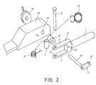
- FIG. 2 is an exploded view of the device of FIG. 1;
- FIG. 3 is an exploded view of a second embodiment of the invention.
- the device of the invention is an acceleration control assembly to allow driving by disabled persons, in this case particularly, but not exclusively, for tetraplegic persons.
- FIGS. 1 and 2 show a pivotable lever 1 which the driver uses to both accelerate and to release acceleration when braking.
- the present vehicle acceleration control and release device is operatively connectable to a vehicle acceleration device (e.g., a fuel injection control system or the like) via an accelerator cable 17 .
- vehicle acceleration device e.g., a fuel injection control system or the like
- the device includes a lever 1 pivotable about a first axis Y (see circle A′) for controlling vehicle acceleration and pivotable about a second axis Z (see circle B′) for releasing acceleration control.
- the first axis Y is perpendicular to the second axis Z.
- a driver would grasp the lever 1 with her hand and apply a first force to move the lever in a slight arc upward to increase pressure against an acceleration cable and call for acceleration. Increased pressure on the acceleration cable would cause the vehicle to accelerate while decreasing pressure on the cable would cause the vehicle to decelerate. In this way, the upward and downward movement of the lever corresponds to varying pressure on a vehicle accelerator pedal.
- FIG. 1 The upward and downward directions are shown in FIG. 1 by arrows A, which corresponds generally to movement in a Z axis of an X-Y-Z system.
- the device includes a pulley 16 mounted perpendicular to the first axis Y, the pulley having a connection 23 for connecting to the accelerator cable 17 and, via a force applied by the pulley to the accelerator cable, to the vehicle acceleration device. Connecting elements connecting the pulley to the lever and rotating the pulley in common with movement of the lever are discussed below. This arrangement thus acts as a means for interfacing with the vehicle acceleration device.
- the device operates such that with no force applied by a driver to the lever, the lever and the pulley rest in a neutral position calling for no acceleration from the vehicle acceleration device with no force being applied by the pulley on the accelerator cable, whereas when the driver applies the first force in a first direction (upward as shown by arrow A in the positive X axis direction) to the lever to cause the lever to move from the neutral position and pivot about the first axis, the pulley is pivoted to create a force on the accelerator cable and call for acceleration from the vehicle acceleration device.
- the pulley when the lever is out of the neutral position and the driver applies a second force in a second direction perpendicular to the first direction and toward the pulley (as shown by left arrow B in the negative Y axis direction), the pulley is automatically returned to the neutral position so that the pulley calls for no acceleration from the vehicle acceleration device.
- the connecting elements releasably connect the pulley 16 to the lever 1 and, when connecting the pulley to the lever, rotate the pulley in common with movement of the lever.
- the first force being applied in the upward direction on the lever causes the lever to pivot about the first axis Y and also causes the pulley to rotate about the first axis Y, the rotation of the pulley creating a force on the accelerator cable 17 calling for acceleration from the vehicle acceleration device.
- the second force in the second direction perpendicular to the first direction and toward the pulley causes the connecting elements to disconnect the pulley from the lever and return the pulley to the neutral position.
- a longitudinal axis of the second axis Z rotates about the first axis Y when the lever 1 and the pulley 16 are out of the neutral position. While rotating about the first axis, the second axis maintains a perpendicular relationship to the first axis.
- Acceleration cable 17 is connected to pulley 16 (shown in FIG. 2).
- Pulley 16 is connected to a first end of pin 10 by setting element 20 .
- a second end of pin 10 is connected to plate 11 . See that plate 11 has a relief 12 .
- the pin 10 is mounted through hole 14 of device body 15 .
- the lever 1 terminates with a forked end 2 having two arms 3 and blind hole 6 .
- the free ends of arms 3 include holes 4 .
- Pin 10 extends through the opening formed by forked end 2 and through hole 14 . During acceleration, relief 12 engages into blind hole 6 .
- Sleeve 7 is mounted between holes 4 by pin 5 . Additionally, a first hindering spring 8 is mounted between an upper surface end of sleeve 7 and an upper arm 3 by inserted pin 5 . The first hindering spring biases fork 3 against plate 11 in order to secure relief 12 in blind hole 6 and to hinder the disconnection of the plate 11 from the lever 1 .
- a second hindering spring 13 is mounted coaxially to sleeve 9 to hinder (resist) the movement of lever 1 against motion in the direction of arrow A and to return pulley 16 to the neutral position. That is, the spring 13 biases the lever to the neutral position, serving as an automatic return-to-neutral (no call for acceleration) position feature.
- the major portion of second hindering spring 13 (the right hand portion as shown in FIG. 2) is mounted coaxially around sleeve 9 and the minor portion of second hindering spring 13 (the left hand portion as shown in FIG. 2) is mounted coaxially around sleeve 7 . In this way, second hindering spring 13 provides a resistance to the driver's upward movement of lever 1 , biasing the lever in the downward direction of arrow A.
- the lever can also be moved in a left direction by the driver as shown by left arrow B of FIG. 1, which generally corresponds to movement in the Y axis of an X-Y-Z system. Arrows B are exaggerated and movement to the left and right would describe a limited arc. Movement in the direction of arrows B (to the left and right) causes lever 1 to pivot about pin 5 in a circular manner as shown by circle B′ in FIG. 1. Spring 8 biases the lever to the right as shown by right arrow B, allowing the relief to engage the blind hole.
- lever 1 When the driver desires to brake, the driver acts on lever 1 to move and hold the lever to the left accordingly to left arrow B. Movement of lever 1 to the left causes relief 12 to be pulled out of blind hole 6 ; that is, relief 12 is released from blind hole 6 .
- second hindering spring 13 causes pin 10 , together with connected plate 11 and pulley 16 , to move to the neutral position so that no action on the acceleration device of the vehicle. In this way, the vehicle does not accelerate when braking, overcoming disadvantages of the prior art described above.
- lever 1 is allowed to return to the right encouraged by first hindering spring 8 so that relief 12 is engaged in blind hole 6 . At this point, the driver can move lever 1 upward or downward as per arrow A for acceleration or deceleration.
- pin 10 and plate 11 could be replaced by different parts for interaction with the acceleration device via the acceleration cable 17 .
- pulley 16 could be replaced by a different part for communicating movement of lever 1 with the vehicle acceleration device.
- FIG. 3 shows a second embodiment of the invention.
- the second embodiment is substantially equal to the first embodiment, so that corresponding parts will be indicated by the same references. Substantially, the main difference between the two embodiments is that the second embodiment is designed for a left-handed driver and includes a speed control device.
- Lever 1 is used during acceleration and braking.
- Lever 1 ends with U-shaped fork element 2 having two arms 3 .
- Pin 5 extends through holes 4 located at the free ends of arms 3 .
- a pin 6 ′ is provided on the body of fork element 2 .
- Pin 5 retains, within an open end of fork element 2 , element assembly 22 , shown in the enlarged particular of FIG. 3.
- Element assembly 22 comprises two sleeves 7 and 9 .
- Element assembly 22 further comprises first hindering spring 8 mounted on sleeve 7 .
- Pin 10 passes through sleeve 9 .
- Plate 11 is attached to one end of pin 10 .
- Plate 11 includes a notch 12 ′ engaging with peg 6 ′ to releasably secure plate 11 to forked element 2 .
- Coaxial to sleeve 9 is second hindering spring 13 set to resist acceleration movement of lever 1 .
- arrow A would be into and out of the paper illustrating the device and arrows B would be up and down along the paper surface.
- Pin 10 passes through hole 14 in body 15 .
- Plate 16 ′ is connected to pin 10 .
- plate 16 ′ can be a pulley.
- Plate 16 ′ includes a retaining element 23 for connection to accelerator cable 17 (shown in FIGS. 1 - 2 ).
- a cruise control device 17 is also mounted to body 15 .
- the cruise control device 24 comprises plate 17 mounted on pin 18 . Also mounted on pin 18 is spring 19 . Pin 18 is mounted in hole 25 of body 15 .
- Pin 20 mounted on plate 17 engages into hole 26 of plate 16 ′. Laterally, a knob 21 is mounted through slot 27 to be tightened against and hold pin 18 in place. If the driver wishes to use the cruise control device 24 , she will tighten knob 21 , holding pin 18 and plate 17 in place. Pin 20 engaged with hole 26 in turn holds plate 16 ′ in place. Plate 16 ′ in turn holds accelerator cable 17 in place until the driver acts to accelerator or brake.
Abstract
Description
- This application is a continuation in part of U.S. patent application Ser. No. 09/720,455.
- The present invention relates to an acceleration control and release device for hand control of vehicle acceleration and positive release of a vehicle accelerator for braking.
- More specifically, the invention relates to such a device employed in the automotive field. The inventive device allows a driver to avoid continued acceleration action during a braking operation.
- The problem of automatically releasing the accelerator during a braking operation is very important in many technical fields, but is particularly important in apparatuses designed for allowing disabled persons to drive.
- At present, acceleration and braking devices for disabled persons are known. Such prior art devices comprise a handle connected to a pivoted lever mounted under the steering member of a motor vehicle or on the floor of the vehicle.
- However, these prior art devices do not allow for the automatic cancellation of the acceleration when braking. In fact, in the case the acceleration handle is not manually, either completely or partially, reset so as to discontinue acceleration, an unavoidable and dangerous interference occurs due to the braking and acceleration actions being active at the same time. This problem can occur for example during emergency maneuvering. Having the vehicle attempt to simultaneously accelerate and brake can render the braking action ineffective.
- AU 663460 describes a hand control system for motor vehicles, which is the closest known prior art for the present invention.
- A main object of the present invention is solving prior art drawbacks by ensuring that the vehicle does not attempt to simultaneously accelerate and brake. That is, the present invention provides a technical solution for vehicle control with acceleration and braking being independent.
- Another object of the present invention is avoiding possible interference when switching from acceleration to braking action.
- It is therefore a specific object of the present invention to provide a device for automatic release of acceleration when a braking action is begun, wherein a vehicle acceleration device, e.g., fuel system to fuel injectors, is operatively connected to the inventive device, e.g., through an accelerator cable and the inventive device includes a pivoted lever for use in both acceleration and braking by movement of the lever in different and substantially perpendicular directions.
- An object of the invention is to provide a device including a cruise control device.
- The present invention will now be described, for illustrative but not limitative purposes, according to its preferred embodiments, with particular reference to the figures of the enclosed drawings, wherein:
- FIG. 1 is a schematic perspective view of a first embodiment according to the invention;
- FIG. 2 is an exploded view of the device of FIG. 1; and
- FIG. 3 is an exploded view of a second embodiment of the invention.
- Making reference to FIGS. 1 and 2, the device of the invention is an acceleration control assembly to allow driving by disabled persons, in this case particularly, but not exclusively, for tetraplegic persons.
- FIGS. 1 and 2 show a pivotable lever 1 which the driver uses to both accelerate and to release acceleration when braking.
- See in FIG. 1 that the present vehicle acceleration control and release device is operatively connectable to a vehicle acceleration device (e.g., a fuel injection control system or the like) via an
accelerator cable 17. The device includes a lever 1 pivotable about a first axis Y (see circle A′) for controlling vehicle acceleration and pivotable about a second axis Z (see circle B′) for releasing acceleration control. The first axis Y is perpendicular to the second axis Z. - A driver would grasp the lever 1 with her hand and apply a first force to move the lever in a slight arc upward to increase pressure against an acceleration cable and call for acceleration. Increased pressure on the acceleration cable would cause the vehicle to accelerate while decreasing pressure on the cable would cause the vehicle to decelerate. In this way, the upward and downward movement of the lever corresponds to varying pressure on a vehicle accelerator pedal.
- The upward and downward directions are shown in FIG. 1 by arrows A, which corresponds generally to movement in a Z axis of an X-Y-Z system.
- The device includes a
pulley 16 mounted perpendicular to the first axis Y, the pulley having aconnection 23 for connecting to theaccelerator cable 17 and, via a force applied by the pulley to the accelerator cable, to the vehicle acceleration device. Connecting elements connecting the pulley to the lever and rotating the pulley in common with movement of the lever are discussed below. This arrangement thus acts as a means for interfacing with the vehicle acceleration device. - The device operates such that with no force applied by a driver to the lever, the lever and the pulley rest in a neutral position calling for no acceleration from the vehicle acceleration device with no force being applied by the pulley on the accelerator cable, whereas when the driver applies the first force in a first direction (upward as shown by arrow A in the positive X axis direction) to the lever to cause the lever to move from the neutral position and pivot about the first axis, the pulley is pivoted to create a force on the accelerator cable and call for acceleration from the vehicle acceleration device.
- Advantageously, when the lever is out of the neutral position and the driver applies a second force in a second direction perpendicular to the first direction and toward the pulley (as shown by left arrow B in the negative Y axis direction), the pulley is automatically returned to the neutral position so that the pulley calls for no acceleration from the vehicle acceleration device.
- As discussed below, the connecting elements releasably connect the
pulley 16 to the lever 1 and, when connecting the pulley to the lever, rotate the pulley in common with movement of the lever. The first force being applied in the upward direction on the lever causes the lever to pivot about the first axis Y and also causes the pulley to rotate about the first axis Y, the rotation of the pulley creating a force on theaccelerator cable 17 calling for acceleration from the vehicle acceleration device. - Advantageously, when the
pulley 16 is out of the neutral position, i.e., when calling for acceleration, the second force in the second direction perpendicular to the first direction and toward the pulley, causes the connecting elements to disconnect the pulley from the lever and return the pulley to the neutral position. See that a longitudinal axis of the second axis Z rotates about the first axis Y when the lever 1 and thepulley 16 are out of the neutral position. While rotating about the first axis, the second axis maintains a perpendicular relationship to the first axis. - With reference to FIG. 1, there is shown an
acceleration cable 17.Acceleration cable 17 is connected to pulley 16 (shown in FIG. 2). - Pulley 16 is connected to a first end of
pin 10 by settingelement 20. A second end ofpin 10 is connected to plate 11. See that plate 11 has arelief 12. - The
pin 10 is mounted throughhole 14 ofdevice body 15. - The lever 1 terminates with a forked
end 2 having twoarms 3 andblind hole 6. The free ends ofarms 3 includeholes 4. -
Pin 10 extends through the opening formed by forkedend 2 and throughhole 14. During acceleration,relief 12 engages intoblind hole 6. - When
relief 12 is engaged intoblind hole 6, upward and downward movement of lever 1 by the driver is translated via plate 11 throughpin 10 andpulley 16 to theaccelerator cable 17, causing acceleration and deceleration. Whenpin 10 and connected plate 11 andpulley 16 are in a neutral position, the acceleration cable is also in a neutral mode where there is no action on the acceleration device of the vehicle. The neutral position is equivalent of taking one's foot off the vehicle accelerator pedal. -
Sleeve 7 is mounted betweenholes 4 bypin 5. Additionally, a first hinderingspring 8 is mounted between an upper surface end ofsleeve 7 and anupper arm 3 by insertedpin 5. The first hinderingspring biases fork 3 against plate 11 in order to securerelief 12 inblind hole 6 and to hinder the disconnection of the plate 11 from the lever 1. - A second hindering
spring 13 is mounted coaxially to sleeve 9 to hinder (resist) the movement of lever 1 against motion in the direction of arrow A and to returnpulley 16 to the neutral position. That is, thespring 13 biases the lever to the neutral position, serving as an automatic return-to-neutral (no call for acceleration) position feature. The major portion of second hindering spring 13 (the right hand portion as shown in FIG. 2) is mounted coaxially aroundsleeve 9 and the minor portion of second hindering spring 13 (the left hand portion as shown in FIG. 2) is mounted coaxially aroundsleeve 7. In this way, second hinderingspring 13 provides a resistance to the driver's upward movement of lever 1, biasing the lever in the downward direction of arrow A. - During acceleration, the driver acts on lever 1 to move the lever's extreme end in an upward or downward direction as shown by
arrow A. Relief 12 is engaged withinblind hole 6, so that the upward or downward movement of the lever's end translates to circular movement ofpulley 16 as illustrated by circle A′ of FIG. 1. The circular movement ofpulley 16 acts onacceleration cable 17 to cause acceleration or deceleration. - The lever can also be moved in a left direction by the driver as shown by left arrow B of FIG. 1, which generally corresponds to movement in the Y axis of an X-Y-Z system. Arrows B are exaggerated and movement to the left and right would describe a limited arc. Movement in the direction of arrows B (to the left and right) causes lever 1 to pivot about
pin 5 in a circular manner as shown by circle B′ in FIG. 1.Spring 8 biases the lever to the right as shown by right arrow B, allowing the relief to engage the blind hole. - When the driver desires to brake, the driver acts on lever 1 to move and hold the lever to the left accordingly to left arrow B. Movement of lever 1 to the left causes
relief 12 to be pulled out ofblind hole 6; that is,relief 12 is released fromblind hole 6. Uponrelief 12 being released fromblind hole 6, second hinderingspring 13causes pin 10, together with connected plate 11 andpulley 16, to move to the neutral position so that no action on the acceleration device of the vehicle. In this way, the vehicle does not accelerate when braking, overcoming disadvantages of the prior art described above. - Once the driver has completed breaking, lever 1 is allowed to return to the right encouraged by first hindering
spring 8 so thatrelief 12 is engaged inblind hole 6. At this point, the driver can move lever 1 upward or downward as per arrow A for acceleration or deceleration. - As already mentioned, the device according to the invention can be realized with modifications which are included in the normal knowledge of one skilled in the art.
- For example, pin 10 and plate 11 could be replaced by different parts for interaction with the acceleration device via the
acceleration cable 17. - Furthermore,
pulley 16 could be replaced by a different part for communicating movement of lever 1 with the vehicle acceleration device. - FIG. 3 shows a second embodiment of the invention.
- The second embodiment is substantially equal to the first embodiment, so that corresponding parts will be indicated by the same references. Substantially, the main difference between the two embodiments is that the second embodiment is designed for a left-handed driver and includes a speed control device.
- Lever 1 is used during acceleration and braking.
- Lever 1 ends with
U-shaped fork element 2 having twoarms 3.Pin 5 extends throughholes 4 located at the free ends ofarms 3. - On the body of
fork element 2, apin 6′ is provided. -
Pin 5 retains, within an open end offork element 2,element assembly 22, shown in the enlarged particular of FIG. 3.Element assembly 22 comprises twosleeves Element assembly 22 further comprises first hinderingspring 8 mounted onsleeve 7. -
Pin 10 passes throughsleeve 9. Plate 11 is attached to one end ofpin 10. Plate 11 includes anotch 12′ engaging withpeg 6′ to releasably secure plate 11 to forkedelement 2. - Coaxial to
sleeve 9 is second hinderingspring 13 set to resist acceleration movement of lever 1. As shown in FIG. 3, arrow A would be into and out of the paper illustrating the device and arrows B would be up and down along the paper surface. -
Pin 10 passes throughhole 14 inbody 15.Plate 16′ is connected to pin 10. As shown,plate 16′ can be a pulley.Plate 16′ includes a retainingelement 23 for connection to accelerator cable 17 (shown in FIGS. 1-2). - A
cruise control device 17 is also mounted tobody 15. Thecruise control device 24 comprisesplate 17 mounted onpin 18. Also mounted onpin 18 isspring 19.Pin 18 is mounted in hole 25 ofbody 15. -
Pin 20 mounted onplate 17 engages intohole 26 ofplate 16′. Laterally, aknob 21 is mounted throughslot 27 to be tightened against and holdpin 18 in place. If the driver wishes to use thecruise control device 24, she will tightenknob 21, holdingpin 18 andplate 17 in place.Pin 20 engaged withhole 26 in turn holdsplate 16′ in place.Plate 16′ in turn holdsaccelerator cable 17 in place until the driver acts to accelerator or brake. - The present invention has been described for illustrative but not limitative purposes, according to its preferred embodiments, but it is to be understood that modifications and/or changes can be introduced by those skilled in the art without departing from the relevant scope of the invention.
Claims (16)
Priority Applications (1)
| Application Number | Priority Date | Filing Date | Title |
|---|---|---|---|
| US10/434,178 US6749535B2 (en) | 1998-06-26 | 2003-05-09 | Acceleration control and release device |
Applications Claiming Priority (5)
| Application Number | Priority Date | Filing Date | Title |
|---|---|---|---|
| IT98RM000429A IT1299535B1 (en) | 1998-06-26 | 1998-06-26 | AUTOMATIC ACCELERATOR RELEASE DEVICE DURING BRAKING PHASE |
| ITRM98A000429 | 1998-06-26 | ||
| ITRM98A0429 | 1998-06-26 | ||
| US72045501A | 2001-02-26 | 2001-02-26 | |
| US10/434,178 US6749535B2 (en) | 1998-06-26 | 2003-05-09 | Acceleration control and release device |
Related Parent Applications (3)
| Application Number | Title | Priority Date | Filing Date |
|---|---|---|---|
| PCT/IT1999/000190 Continuation-In-Part WO2000000362A1 (en) | 1998-06-26 | 1999-06-25 | Device for automatic release of accelerator during the braking action |
| US09720455 Continuation-In-Part | 2001-02-26 | ||
| US72045501A Continuation-In-Part | 1998-06-26 | 2001-02-26 |
Publications (2)
| Publication Number | Publication Date |
|---|---|
| US20030195085A1 true US20030195085A1 (en) | 2003-10-16 |
| US6749535B2 US6749535B2 (en) | 2004-06-15 |
Family
ID=28793338
Family Applications (1)
| Application Number | Title | Priority Date | Filing Date |
|---|---|---|---|
| US10/434,178 Expired - Fee Related US6749535B2 (en) | 1998-06-26 | 2003-05-09 | Acceleration control and release device |
Country Status (1)
| Country | Link |
|---|---|
| US (1) | US6749535B2 (en) |
Families Citing this family (4)
| Publication number | Priority date | Publication date | Assignee | Title |
|---|---|---|---|---|
| US7954591B2 (en) * | 2007-09-25 | 2011-06-07 | John Livingston Kazanchy | Safety interlock system for hand operated accelerator control devices |
| US7950489B2 (en) * | 2007-09-27 | 2011-05-31 | John Livingston Kazanchy | Safety interlock system for left foot operated accelerator control devices |
| US8096207B2 (en) * | 2008-11-14 | 2012-01-17 | Keith Herbert Howell | Vehicle hand control apparatus |
| ITTO20120912A1 (en) | 2012-10-16 | 2014-04-17 | Carrozzeria 71 S R L | MANUAL DEVICE OF THE ACCELERATOR OF A MOTOR VEHICLE " |
Citations (4)
| Publication number | Priority date | Publication date | Assignee | Title |
|---|---|---|---|---|
| US2602348A (en) * | 1951-02-19 | 1952-07-08 | Raymond K Wilson | Hand control for automotive vehicles |
| US2855797A (en) * | 1953-10-23 | 1958-10-14 | Robert K Gillen | Automobile drive control |
| US2899835A (en) * | 1959-08-18 | Hand control for automobile brake and accelerator pedals | ||
| US5129492A (en) * | 1991-03-05 | 1992-07-14 | Contact Technologies Inc. | Steering column mounted hand control |
Family Cites Families (15)
| Publication number | Priority date | Publication date | Assignee | Title |
|---|---|---|---|---|
| US2731850A (en) | 1956-01-24 | For motor vehicles | ||
| US2523491A (en) | 1946-01-19 | 1950-09-26 | Chrysler Corp | Vehicle control |
| US2777335A (en) | 1954-10-04 | 1957-01-15 | William M Engberg | Hand apparatus for controlling brakes and accelerators |
| US2875638A (en) | 1956-07-06 | 1959-03-03 | Leverage Hand Brake Company | Hand control for brake and accelerator |
| US4436191A (en) | 1981-12-15 | 1984-03-13 | Perry William E | Automobile hand control |
| DE3333258C2 (en) | 1983-09-15 | 1985-07-11 | Ford-Werke AG, 5000 Köln | Brake-accelerator manual control device for the operation of a motor vehicle by handicapped drivers |
| US4627522A (en) | 1984-12-12 | 1986-12-09 | General Motors Corporation | Hand engine and brake control mechanism for a vehicle |
| JPS6361639A (en) | 1986-09-02 | 1988-03-17 | Nippon Cable Syst Inc | Transmission control |
| NL8701503A (en) | 1987-06-26 | 1989-01-16 | Timotheus Theodorus Van Der Vl | COMBINED GAS BRAKE PEDAL SYSTEM. |
| US4998983A (en) | 1989-06-02 | 1991-03-12 | Drive-Master Corp. | Manually operated apparatus for controlling the brake and accelerator of a motor vehicle |
| US4946013A (en) | 1989-06-12 | 1990-08-07 | Conlyn Jr Andrew C | Apparatus for manual operation of vehicle brake and accelerator pedals |
| US4993509A (en) | 1990-02-02 | 1991-02-19 | Keith Howell | Vehicle hand control device |
| US5103946A (en) | 1990-11-06 | 1992-04-14 | Team Mfg., Inc. | Brake and accelerator controls for handicapped |
| GB2290509B (en) | 1994-06-22 | 1998-02-11 | Jill Webber | Hand controls for disabled drivers |
| FR2760698B1 (en) | 1997-03-13 | 1999-06-11 | Peugeot | CONTROL DEVICE FOR A MOTOR VEHICLE GEARBOX |
-
2003
- 2003-05-09 US US10/434,178 patent/US6749535B2/en not_active Expired - Fee Related
Patent Citations (4)
| Publication number | Priority date | Publication date | Assignee | Title |
|---|---|---|---|---|
| US2899835A (en) * | 1959-08-18 | Hand control for automobile brake and accelerator pedals | ||
| US2602348A (en) * | 1951-02-19 | 1952-07-08 | Raymond K Wilson | Hand control for automotive vehicles |
| US2855797A (en) * | 1953-10-23 | 1958-10-14 | Robert K Gillen | Automobile drive control |
| US5129492A (en) * | 1991-03-05 | 1992-07-14 | Contact Technologies Inc. | Steering column mounted hand control |
Also Published As
| Publication number | Publication date |
|---|---|
| US6749535B2 (en) | 2004-06-15 |
Similar Documents
| Publication | Publication Date | Title |
|---|---|---|
| JP4887509B2 (en) | Automobile driving assistance device | |
| EP1759944B1 (en) | Parking brake apparatus | |
| US6161449A (en) | Steering wheel rotating apparatus for physically handicapped persons | |
| US5775174A (en) | Vehicular foot-operated parking brake control apparatus | |
| US6749535B2 (en) | Acceleration control and release device | |
| US5439429A (en) | Vehicle safety system for correcting simultaneous actuation of brake and acceleration pedals | |
| US5813944A (en) | Hand-operated speed control apparatus for attachment to a motor vehicle | |
| EP0804350B1 (en) | Selector lever lock device for an automatic transmission in a motor vehicle | |
| EP0480108B1 (en) | Parking-brake operating device | |
| JPH02502861A (en) | Control mechanism for driving a vehicle | |
| US4109745A (en) | Manually operated throttle control for four wheel drive vehicle | |
| US4353443A (en) | Vehicle throttle control | |
| JPH0351252Y2 (en) | ||
| JP3067074B2 (en) | Operation lever support structure | |
| KR100397852B1 (en) | parking brake system of vehicle | |
| JPH0644741Y2 (en) | Car driving system for the physically handicapped | |
| JPH0437790Y2 (en) | ||
| KR100488782B1 (en) | Safety device of a handling lever for a power take off | |
| KR100269763B1 (en) | Accelerator pedal structure | |
| JPS6347540Y2 (en) | ||
| JPH0351251Y2 (en) | ||
| KR0150615B1 (en) | A car for a disabled person | |
| JPH0450183Y2 (en) | ||
| JPH051490Y2 (en) | ||
| JPS62166123A (en) | Hill holder device for automobile |
Legal Events
| Date | Code | Title | Description |
|---|---|---|---|
| AS | Assignment |
Owner name: 50% TO: GUIDOSIMPLEX S.N.C. DI GIANCARLO VENTURINI Free format text: ASSIGNMENT OF ASSIGNORS INTEREST;ASSIGNOR:SPINNATO, DARIO;REEL/FRAME:013755/0998 Effective date: 20030609 Owner name: 50% TO: SISTEMA GUIDA 2000 S.R.L., ITALY Free format text: ASSIGNMENT OF ASSIGNORS INTEREST;ASSIGNOR:SPINNATO, DARIO;REEL/FRAME:013755/0998 Effective date: 20030609 |
|
| REMI | Maintenance fee reminder mailed | ||
| LAPS | Lapse for failure to pay maintenance fees | ||
| STCH | Information on status: patent discontinuation |
Free format text: PATENT EXPIRED DUE TO NONPAYMENT OF MAINTENANCE FEES UNDER 37 CFR 1.362 |
|
| FP | Lapsed due to failure to pay maintenance fee |
Effective date: 20080615 |