US2531702A - Support for electrical machines - Google Patents
Support for electrical machines Download PDFInfo
- Publication number
- US2531702A US2531702A US787000A US78700047A US2531702A US 2531702 A US2531702 A US 2531702A US 787000 A US787000 A US 787000A US 78700047 A US78700047 A US 78700047A US 2531702 A US2531702 A US 2531702A
- Authority
- US
- United States
- Prior art keywords
- generator
- latch
- arm
- actuating lever
- motor
- Prior art date
- Legal status (The legal status is an assumption and is not a legal conclusion. Google has not performed a legal analysis and makes no representation as to the accuracy of the status listed.)
- Expired - Lifetime
Links
Images

Classifications
-
- H—ELECTRICITY
- H02—GENERATION; CONVERSION OR DISTRIBUTION OF ELECTRIC POWER
- H02K—DYNAMO-ELECTRIC MACHINES
- H02K5/00—Casings; Enclosures; Supports
- H02K5/26—Means for adjusting casings relative to their supports
-
- Y—GENERAL TAGGING OF NEW TECHNOLOGICAL DEVELOPMENTS; GENERAL TAGGING OF CROSS-SECTIONAL TECHNOLOGIES SPANNING OVER SEVERAL SECTIONS OF THE IPC; TECHNICAL SUBJECTS COVERED BY FORMER USPC CROSS-REFERENCE ART COLLECTIONS [XRACs] AND DIGESTS
- Y10—TECHNICAL SUBJECTS COVERED BY FORMER USPC
- Y10T—TECHNICAL SUBJECTS COVERED BY FORMER US CLASSIFICATION
- Y10T74/00—Machine element or mechanism
- Y10T74/11—Tripping mechanism
Definitions
- This invention relates to a. mechanism ionsup porting a device, and more particularly to an articulated type bracket used for supporting a device in at least two positions.
- An important object of the invention resides in the provision of a hinged supporting bracket for mounting a generator in driving relationship to a driving member and provided with a latching lever which releasably supports the generator out of engagement with the driving member.
- Another important object of the invention resides in the provision of a hinged supporting bracket for mounting a generator or motor in driving relationship to a, rotatable member and releasably latchable out of driving relationship therewith, and provided with mean for remotely releasing said generatoror motor.
- a still further object of the invention lies in the provision of an articulated bracket carried by a vehicle frame and mounting a generator in driving relationship to one of the vehicle wheels.
- the arrangement being such that when the generator is latched. out of driving relationship with the wheel an actuating lever may be remotely operated to release said generator for driving engagement with said wheel.
- Another object of the invention lies in the provision of an articulated bracket for mounting a generator or the like in driving relationship with a rotatable member and movable into and out of driving relationship with said member by remotely operated means.
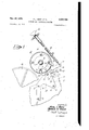
- Figure 1 is a side elevational view of 'thedevice of the invention arranged in latched position, with parts broken away, and shown mounted to the frame structure of a vehicle;
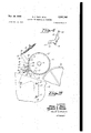
- Figure 2 is a view in side elevationof the device in latched position, but looking at the same from a side of the vehicle opposite to that of Figure 1;
- Figure 3 is a view of the device taken from the'same side of the vehicle as Figure 2, but with the device in released position;
- FIG 4 is a perspective view of "one of the Referring now to Figure 1 of the drawings the reference numeral H) designates the, frame “of a vehicle by which the device of the invention. is
- An articulated supporting bracket I2 is removably securedto the frame H], by screws II, which pass throughopenings l6 and slot 18, in a generator supporting arm 23.
- the arm is pro-- vide'dwwith a transverse hub 22, which "pivotally supports a generator 24, for engagement with a Wheel or rotatable member 26.
- a pin 28 passes through hub 22, for engagement with a pair of generator supporting members 30 and 3
- This generator supporting structure, com prising, members 39 and 31, is carried by the pin 28, to thereby pivotally supportthe genera-- tor, which is provided with a driving wheel 3!, fixed to shaft 36.
- the generator may be lowered to a position of Figure 3 where wheel 26 is in driving engagement with the generator wheel 34, or raised to a position shown in Figures land 2. In the latter position the generator is releasably latched out of contact with the wheel 26 by an actuatin'gilever 38, pivotally carried at 4'0, by one of the members 30 or 3
- the other end of the actuating lever forms a lever arm 44 of suflicient length to give considerable mechanical advantags to permit the generator to be rotated about pin 28, into and out 'of engagement with the rotatable member '26, by pushing or pulling a knob 46 operatively connected toone end of a Bowde'n cable 43, the other end ofwhich is securedtothe lever arm 44 at 5!
- the generator supporting arm 28 Adjacent to the generator pivot pin 28, the generator supporting arm 28 is provided with a latch engaging portion or cam 52. for engagement with the pawl or latch 42 to rele'asably hold the generator out of engagement with the driving wheel 26.
- a coiled spring 54 encircles the hub 22.
- the spring has one of its ends engaging a lip '56 of the supporting arm 20, and its other end abutting a projection 58 carried by the lowerend oi the actuating lever.
- actuating lever 38 is rotated clockwise, see Figure 2, by pulling on knob 48. It will be noted that the actuating lever is rotated in the same direction as the generator must be rotated to be released.
- the cam 52 is provided with a second cam face 62 formed so that when the actuating lever is rotated clockwise from the position shown in Figure 2 the latch 52 slides along the cam face 62 until the latch completely disengages the latter cam face, at which time the generator is rotated clockwise by spring 54 to thereby position the generator in driving engagement with wheel 25.
- the latch 42 is provided-with a finger 64 constituted to engage the cam 52.
- a mechanism for positioning a, motor or generator in driving relationship with a rotatable member comprising a supporting arm, means for rotatably mounting a motor or generator on said arm, means including an actuating lever pivotally carried by said first named means for moving said motor or generator into and out of driving relationship with said rotatable member and for releasably holding said motor or generator out of driving relationship, said supporting arm being formed with a cam thereon, and said actuating lever being provided with a latch for engagement with said cam to thereby releasably hold said motor or generator out of driving relationship with said rotatable member, and a spring interposed between the arm and actuating lever and arranged so that the spring produces rotation of said motor or generator with respect to said arm when the latch is disengaged from said cam.
- a mechanism for mounting a device having two positions comprisin a supporting arm, means for rotatably mounting a device on said arm, means for selectively positioning said devicein any one of its positions including an actuating lever constituted to be pivotally carried by said first named means and having a latch formed on oneend thereof, said supportingarm having a latch engagin portion formed thereon constructed'and arranged for engagement with said latch-to releasably holdsaid device in one position, and means connected to said lever to remotely disengage said latch from said latch engaging portion.
- a mechanism for mounting a devic having two positions comprising a supporting arm, means for rotatably mounting a device on said arm, means for selectively positionin said device in any one of its positions including an actuating lever constituted to be carried by said first named means and having a latch formed on one end thereof, said supporting'arm having a cam formed thereon constructed and arranged for engagement with said latch to releasably hold said device in one of its positions, and a Bowden cable operatively connected to said actuating lever for remotely operating said lever to thereby move said device to its other position.
- a mechanism for positioning a motor or generator in driving relationship to a rotatable member comprising a fixed supporting arm, means for rotatably mounting a motor or generator on said arm, an actuating lever constituted to be pivotally carried by said means and having a latch formed on one end thereof, said supporting arm having a latch engaging portion formed thereon constructed and arranged for engagement with said latch to releasably hold said motor or generator, and a spring interposed between said arm and lever, said spring having one end in engagement with said latch and the other end abutting said arm, whereby said motor or generator is rotatedinto driving relationship with said rotatable member when said latch is disengaged from said cam.
- a mechanism for positioning a motor or generator in driving relationship with a rotatable member comprising a supporting arm provided with a hub, means for rotatably supporting a motor or generator by said hub, and means in cluding an actuating lever carried bysa-id first named means for moving said motor or genera tor into and out of drivin relationship with said rotatable member and for releasably holding said motor or generator out of driving relationship, said supporting arm bein formed with a cam thereon and said actuating lever being provided with a latch for engagement with said cam to thereby releasably hold said motor or generator out of driving relationship with said rotatable member.
- a mechanism for positioning a motor or generator, in driving relationship with a rotatable member comprising a supportin arm provided with a hub, means for rotatably supporting a motor or generator by said hub, means including an actuating lever carriedby said first named means for moving said motor or generator into and out of driving relationship with said rotatable member and for releasably holding said motor or generator out of driving relationship, said supporting arm being formed with a cam thereon and said actuating lever being provided with a latch for engagement with said cam to thereby hold said motor or generator out of driving relationship with said rotatable member, and means remotely located from said actuating lever and operatively connected thereto for positioning said motor or generator.
- a mechanismior supporting a device in two positions comprising an arm, means for rotatably mounting said device on the arm, a latch engaging portion integral with said arm, and an actuating lever pivotally carried by said means and having a latch, integral therewith constitutedtoengage said latch..engagin portion-to releasably hold said device in one of its positions, said actuating lever being .actuable by rotary-action to release said latch to thereby move said device to its other position.
- An articulated bracket for carrying a gen- 5 8 erator in driving relationship to a driving mem- REFERENCES CITED ber comprising a supporting arm provided with I I p t engaging portion, upportin Structure
- a manually operated lever having UNITED STATES PATENTS a latch thereon for engaging said latch engaging portion of said arm, said lever being pivotally Number Name Date mounted on said supporting structure to receive 2, 26,3 3 Bush Dec. 131, 1935 rotary movement to thereby disengage said arm.
- 10 2 McDermo t July 2 1937 ROYAL J. REEK. 2,430,429 Katcher Nov. 4, 1947 FRANKLIN O. WISMAN.
Description
Nov 28, 1950 R, J, REEK ET AL 2,531,702
SUPPORT FOR ELECTRICAL MACHINES Filed Nov. 19, 1947 3 Sheets-Sheet l INVENTOEQS ggmmm MMAN A T TOIENE Y Nova 28, 1950 R. J. REEK ET AL 2,531,702
SUPPORT FOR ELECTRICAL MACHINES Filed Nov. 19, 1947 3 Sheets-Sheet 2 INVENTOEIS Earn .12 E551: fPANKL/N 0. lmmn ATTOENE Y Nov. 28, 1950 u. REEK ETAL SUPPORT FOR ELECTRICAL MACHINES 3 Sheets-Sheet 3 Filed Nov. 19, 1947 INVENTOEJS Ram J EEEK fiuuwu a Mama ATTORNEY Patented Nov. 28, 1950 UNITED STATES PATENT OFFICE Bend, I-mL, "assignors to Bendix Aviation Cor poration, South Bond, 1116., a corporation of Delaware Application November 19, 1947, Serial No. 787;000
8 Claims. 1
This invention relates to a. mechanism ionsup porting a device, and more particularly to an articulated type bracket used for supporting a device in at least two positions.
An important object of the invention resides in the provision of a hinged supporting bracket for mounting a generator in driving relationship to a driving member and provided with a latching lever which releasably supports the generator out of engagement with the driving member.
Another important object of the invention resides in the provision of a hinged supporting bracket for mounting a generator or motor in driving relationship to a, rotatable member and releasably latchable out of driving relationship therewith, and provided with mean for remotely releasing said generatoror motor.
A still further object of the invention lies in the provision of an articulated bracket carried by a vehicle frame and mounting a generator in driving relationship to one of the vehicle wheels. The arrangement being such that when the generator is latched. out of driving relationship with the wheel an actuating lever may be remotely operated to release said generator for driving engagement with said wheel.
Another object of the invention lies in the provision of an articulated bracket for mounting a generator or the like in driving relationship with a rotatable member and movable into and out of driving relationship with said member by remotely operated means. i
The above and other objects and features the invention will be apparent from the followlug description of the apparatus taken in connection with the accompanying drawings which form a part of this specification, and in which:
Figure 1 is a side elevational view of 'thedevice of the invention arranged in latched position, with parts broken away, and shown mounted to the frame structure of a vehicle;
Figure 2 is a view in side elevationof the device in latched position, but looking at the same from a side of the vehicle opposite to that of Figure 1;
Figure 3 is a view of the device taken from the'same side of the vehicle as Figure 2, but with the device in released position;
Figure 4 is a perspective view of "one of the Referring now to Figure 1 of the drawings the reference numeral H) designates the, frame "of a vehicle by which the device of the invention. is
carried. An articulated supporting bracket I2 is removably securedto the frame H], by screws II, which pass throughopenings l6 and slot 18, in a generator supporting arm 23. The arm is pro-- vide'dwwith a transverse hub 22, which "pivotally supports a generator 24, for engagement with a Wheel or rotatable member 26. A pin 28 passes through hub 22, for engagement with a pair of generator supporting members 30 and 3|, fastened to each side of the generator by screws 32. This generator supporting structure, com prising, members 39 and 31, is carried by the pin 28, to thereby pivotally supportthe genera-- tor, which is provided with a driving wheel 3!, fixed to shaft 36. The generator may be lowered to a position of Figure 3 where wheel 26 is in driving engagement with the generator wheel 34, or raised to a position shown in Figures land 2. In the latter position the generator is releasably latched out of contact with the wheel 26 by an actuatin'gilever 38, pivotally carried at 4'0, by one of the members 30 or 3|. At one end the actuating lever is provided with a latch or Dav/H123, integral with the actuating lever and disposed adjacentto the pivot 4!]. The other end of the actuating lever forms a lever arm 44 of suflicient length to give considerable mechanical advantags to permit the generator to be rotated about pin 28, into and out 'of engagement with the rotatable member '26, by pushing or pulling a knob 46 operatively connected toone end of a Bowde'n cable 43, the other end ofwhich is securedtothe lever arm 44 at 5! Adjacent to the generator pivot pin 28, the generator supporting arm 28 is provided with a latch engaging portion or cam 52. for engagement with the pawl or latch 42 to rele'asably hold the generator out of engagement with the driving wheel 26. A coiled spring 54 encircles the hub 22. The spring has one of its ends engaging a lip '56 of the supporting arm 20, and its other end abutting a projection 58 carried by the lowerend oi the actuating lever. With this arrangement of the coiled spring there is a tendency for the generator to be rotated in a counterclockwise direction about pivot pin 22, as viewed in Figure 1. The can-152 is profiled along cam face 6c in such a mannerthat rotation of the actuating lever 38 in a counterclockwise dh rection, as viewed in Figure 3, to'thereby rotate the generator out of driving relationship with wheel 25, will only cause the pawl to slide along the face 60 carrying thergenerator wiithit,
that is, allow the actuating lever to rotate about pivot 28 with the generator until the pawl passes beyond cam face 62, at which time the actuating lever is rotated in a counterclockwise direction around pivot 40 to releasably latch the generator in position, see Figures 1 and 2. It will be noted that to rotate the generator out of driving relationship with wheel 26, as shown inFigure 3, it is only necessary to push on knob 46, connected to one end of the Bowden cable, whereby the generator is rotated to the position of Figures 1 and 2.
To release the generator so that wheel 34 thereof is in driving relationship with wheel 26, see Figure 3, actuating lever 38 is rotated clockwise, see Figure 2, by pulling on knob 48. It will be noted that the actuating lever is rotated in the same direction as the generator must be rotated to be released. To accomplish this action, the cam 52 is provided with a second cam face 62 formed so that when the actuating lever is rotated clockwise from the position shown in Figure 2 the latch 52 slides along the cam face 62 until the latch completely disengages the latter cam face, at which time the generator is rotated clockwise by spring 54 to thereby position the generator in driving engagement with wheel 25. To prevent lateral movement of the actuating lever 38 and generator 24 with respect to the supporting arm 29, the latch 42 is provided-with a finger 64 constituted to engage the cam 52.
"Although this invention has been described in connection with certain specific embodiments, the principles are susceptible of numerous other applications that will readily occur to persons skilled in the art.
Having thus described the various features of the invention, what we claim as new and desire to secure by Letters Patent is:
We claim:
l. A mechanism for positioning a, motor or generator in driving relationship with a rotatable member comprising a supporting arm, means for rotatably mounting a motor or generator on said arm, means including an actuating lever pivotally carried by said first named means for moving said motor or generator into and out of driving relationship with said rotatable member and for releasably holding said motor or generator out of driving relationship, said supporting arm being formed with a cam thereon, and said actuating lever being provided with a latch for engagement with said cam to thereby releasably hold said motor or generator out of driving relationship with said rotatable member, and a spring interposed between the arm and actuating lever and arranged so that the spring produces rotation of said motor or generator with respect to said arm when the latch is disengaged from said cam.
2. A mechanism for mounting a device having two positions comprisin a supporting arm, means for rotatably mounting a device on said arm, means for selectively positioning said devicein any one of its positions including an actuating lever constituted to be pivotally carried by said first named means and having a latch formed on oneend thereof, said supportingarm having a latch engagin portion formed thereon constructed'and arranged for engagement with said latch-to releasably holdsaid device in one position, and means connected to said lever to remotely disengage said latch from said latch engaging portion.
.. 3.. A mechanism for mounting a devic having two positions comprising a supporting arm, means for rotatably mounting a device on said arm, means for selectively positionin said device in any one of its positions including an actuating lever constituted to be carried by said first named means and having a latch formed on one end thereof, said supporting'arm having a cam formed thereon constructed and arranged for engagement with said latch to releasably hold said device in one of its positions, and a Bowden cable operatively connected to said actuating lever for remotely operating said lever to thereby move said device to its other position.
4. A mechanism for positioning a motor or generator in driving relationship to a rotatable member and comprising a fixed supporting arm, means for rotatably mounting a motor or generator on said arm, an actuating lever constituted to be pivotally carried by said means and having a latch formed on one end thereof, said supporting arm having a latch engaging portion formed thereon constructed and arranged for engagement with said latch to releasably hold said motor or generator, and a spring interposed between said arm and lever, said spring having one end in engagement with said latch and the other end abutting said arm, whereby said motor or generator is rotatedinto driving relationship with said rotatable member when said latch is disengaged from said cam.
5. A mechanism for positioning a motor or generator in driving relationship with a rotatable member comprising a supporting arm provided with a hub, means for rotatably supporting a motor or generator by said hub, and means in cluding an actuating lever carried bysa-id first named means for moving said motor or genera tor into and out of drivin relationship with said rotatable member and for releasably holding said motor or generator out of driving relationship, said supporting arm bein formed with a cam thereon and said actuating lever being provided with a latch for engagement with said cam to thereby releasably hold said motor or generator out of driving relationship with said rotatable member.
6. A mechanism for positioning a motor or generator, in driving relationship with a rotatable member comprising a supportin arm provided with a hub, means for rotatably supporting a motor or generator by said hub, means including an actuating lever carriedby said first named means for moving said motor or generator into and out of driving relationship with said rotatable member and for releasably holding said motor or generator out of driving relationship, said supporting arm being formed with a cam thereon and said actuating lever being provided with a latch for engagement with said cam to thereby hold said motor or generator out of driving relationship with said rotatable member, and means remotely located from said actuating lever and operatively connected thereto for positioning said motor or generator.
7. A mechanismior supporting a device in two positions comprising an arm, means for rotatably mounting said device on the arm, a latch engaging portion integral with said arm, and an actuating lever pivotally carried by said means and having a latch, integral therewith constitutedtoengage said latch..engagin portion-to releasably hold said device in one of its positions, said actuating lever being .actuable by rotary-action to release said latch to thereby move said device to its other position. 8. An articulated bracket for carrying a gen- 5 8 erator in driving relationship to a driving mem- REFERENCES CITED ber comprising a supporting arm provided with I I p t engaging portion, upportin Structure The following references are of record in the. adapted to carry a motor or generator and confile of this P structed and arranged to be pivotally mounted 5 to said arm, a manually operated lever having UNITED STATES PATENTS a latch thereon for engaging said latch engaging portion of said arm, said lever being pivotally Number Name Date mounted on said supporting structure to receive 2, 26,3 3 Bush Dec. 131, 1935 rotary movement to thereby disengage said arm. 10 2 McDermo t July 2 1937 ROYAL J. REEK. 2,430,429 Katcher Nov. 4, 1947 FRANKLIN O. WISMAN.
Priority Applications (1)
| Application Number | Priority Date | Filing Date | Title |
|---|---|---|---|
| US787000A US2531702A (en) | 1947-11-19 | 1947-11-19 | Support for electrical machines |
Applications Claiming Priority (1)
| Application Number | Priority Date | Filing Date | Title |
|---|---|---|---|
| US787000A US2531702A (en) | 1947-11-19 | 1947-11-19 | Support for electrical machines |
Publications (1)
| Publication Number | Publication Date |
|---|---|
| US2531702A true US2531702A (en) | 1950-11-28 |
Family
ID=25140151
Family Applications (1)
| Application Number | Title | Priority Date | Filing Date |
|---|---|---|---|
| US787000A Expired - Lifetime US2531702A (en) | 1947-11-19 | 1947-11-19 | Support for electrical machines |
Country Status (1)
| Country | Link |
|---|---|
| US (1) | US2531702A (en) |
Cited By (2)
| Publication number | Priority date | Publication date | Assignee | Title |
|---|---|---|---|---|
| US2885165A (en) * | 1954-11-12 | 1959-05-05 | Clayton Manufacturing Co | Engine support |
| US2983457A (en) * | 1956-12-18 | 1961-05-09 | Toro Ind Inc | Magnetic tape recorder |
Citations (3)
| Publication number | Priority date | Publication date | Assignee | Title |
|---|---|---|---|---|
| US2026373A (en) * | 1935-07-31 | 1935-12-31 | Gen Electric | Operating mechanism |
| US2088029A (en) * | 1935-09-26 | 1937-07-27 | Mcdermott Carl | Bicycle generator |
| US2430429A (en) * | 1944-02-25 | 1947-11-04 | Chefford Master Mfg Co Inc | Bracket for bicycle generators or the like |
-
1947
- 1947-11-19 US US787000A patent/US2531702A/en not_active Expired - Lifetime
Patent Citations (3)
| Publication number | Priority date | Publication date | Assignee | Title |
|---|---|---|---|---|
| US2026373A (en) * | 1935-07-31 | 1935-12-31 | Gen Electric | Operating mechanism |
| US2088029A (en) * | 1935-09-26 | 1937-07-27 | Mcdermott Carl | Bicycle generator |
| US2430429A (en) * | 1944-02-25 | 1947-11-04 | Chefford Master Mfg Co Inc | Bracket for bicycle generators or the like |
Cited By (2)
| Publication number | Priority date | Publication date | Assignee | Title |
|---|---|---|---|---|
| US2885165A (en) * | 1954-11-12 | 1959-05-05 | Clayton Manufacturing Co | Engine support |
| US2983457A (en) * | 1956-12-18 | 1961-05-09 | Toro Ind Inc | Magnetic tape recorder |
Similar Documents
| Publication | Publication Date | Title |
|---|---|---|
| US4057220A (en) | Ratchet type operator for cable winches and the like | |
| US3490715A (en) | Rewind control mechanism with slotted cam and toggle-activated pawl | |
| EP0601211A4 (en) | Bicycle brake lever assembly. | |
| US2770326A (en) | Brake mechanism | |
| US2531702A (en) | Support for electrical machines | |
| US4270708A (en) | Cable winder | |
| US2422065A (en) | Device for stretching flexible members | |
| US2924987A (en) | Control apparatus | |
| US2630983A (en) | Aerial camera mount and control means therefor | |
| GB1487657A (en) | Control mechanism | |
| US4487380A (en) | Reeling device | |
| US2769344A (en) | Remote control mechanism for television receivers | |
| US2031830A (en) | Windshield cleaner | |
| US1750361A (en) | Speed-adjusting device for motor governors | |
| US2943159A (en) | Interval timer | |
| US2929041A (en) | Control and switch assembly therefor | |
| US3021720A (en) | Control devices for adjustable driving mounts | |
| US2161732A (en) | Clutch | |
| US2413577A (en) | Airplane control mechanism | |
| US2190447A (en) | Remote control apparatus | |
| US2066978A (en) | Carriage return | |
| US3099023A (en) | Wrap spring adjustment lock for boat windshield | |
| US2826092A (en) | Rotary drive control mechanisms | |
| US2074797A (en) | Pedal-operated automatic gearchange | |
| US1856223A (en) | Antenna reel |