US3028126A - Three axis controller - Google Patents
Three axis controller Download PDFInfo
- Publication number
- US3028126A US3028126A US28175A US2817560A US3028126A US 3028126 A US3028126 A US 3028126A US 28175 A US28175 A US 28175A US 2817560 A US2817560 A US 2817560A US 3028126 A US3028126 A US 3028126A
- Authority
- US
- United States
- Prior art keywords
- control
- ring
- plane
- ring member
- movement
- Prior art date
- Legal status (The legal status is an assumption and is not a legal conclusion. Google has not performed a legal analysis and makes no representation as to the accuracy of the status listed.)
- Expired - Lifetime
Links
Images


Classifications
-
- G—PHYSICS
- G05—CONTROLLING; REGULATING
- G05G—CONTROL DEVICES OR SYSTEMS INSOFAR AS CHARACTERISED BY MECHANICAL FEATURES ONLY
- G05G1/00—Controlling members, e.g. knobs or handles; Assemblies or arrangements thereof; Indicating position of controlling members
- G05G1/58—Rests or guides for relevant parts of the operator's body
- G05G1/62—Arm rests
-
- B—PERFORMING OPERATIONS; TRANSPORTING
- B64—AIRCRAFT; AVIATION; COSMONAUTICS
- B64C—AEROPLANES; HELICOPTERS
- B64C13/00—Control systems or transmitting systems for actuating flying-control surfaces, lift-increasing flaps, air brakes, or spoilers
- B64C13/02—Initiating means
- B64C13/04—Initiating means actuated personally
- B64C13/042—Initiating means actuated personally operated by hand
- B64C13/0421—Initiating means actuated personally operated by hand control sticks for primary flight controls
Definitions
- FIG 3 FLIGHT 5 VEHICLE INVENTOR.
- This invention relates to control devices, more particularly, it relates to devices for controlling the attitude of a vehicle in flight either within or outside the atmosphere.
- the invention comprises a three-axis controller, that is, a single control device by which the attitude of a vehicle in flight may be controlled about three orthogonal axes.
- a difficulty of prior three-axis controllers is the fact that proper force characteristics could not be provided without prohibitive size and weight of the controller.
- the proper force characteristics are necessary to provide the pilot with a sense or feel of the position of the vehicle being controlled.
- a unitary threeaxes controller comprising three rings assembled to move one each in the planes of yaw, pitch and roll. Proportional movement of the controlled flight vehicle in planes corresponding to the planes of movement of respective rings is accomplished by making the signals from a potentiometer to an actuator for the control elements of the flight vehicle, proportional to the ring movements.
- a potentiometer to an actuator for the control elements of the flight vehicle, proportional to the ring movements.
- Resistance to movement of each ring is provided by relative movement between a shaped cam surface attached to the ring, and a cooperating cam follower, the shape of the cam surface and arrangement of the camrning elements providing a resistance to movement of the ring as it moves from the zero position.
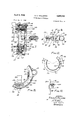
- FIG. 1 is a perspective view of the apparatus as applied
- FIG. 2 is a side elevational view of the three-axis controller
- FIG. 3 is an end elevational view of the apparatus from the front
- FIG. 4 is an end elevational view of the apparatus from the rear
- FIG. 5 is a vertical cross-section of the apparatus on line 5-5 of FIG. 3; 7
- FIG. 6 is a vertical cross-section of the apparatus on line 6-6 of FIG. 3 showing a view opposed to that of FIG. 5;
- FIG. 7 is a partial plan section taken on the line 7--7 of FIG. 2;
- FIG. 8 is a partial end elevational view taken on line 8-8 of FIG. 2;
- FIG. 9 is a plan section taken on line 99 of FIG. 2;
- FIG. 10 is a side elevational view of the roll cam
- FIG. 11 is a descriptive view of the yaw cam
- FIG. 12 is an end elevational view of the roll cam
- FIG. 13 is a descriptive view in end elevation of the roll cam
- FIG. 14 is a side elevational view of the pitch cam
- FIG. 15 is a schematic drawing diagrammatically illustrating the manner in which proportional signals are relayed from the controller to the controlled device.
- FIG. 1 the control device itself is shown generally at 20 mounted on support member 22 for operation.
- Yaw control ring 24 is rotatably mounted on support 22 for rotation along the yaw plane through an angle of 20 on either side of the null position, as shown in FIG. 11.
- Roll control ring 26 is concentrically mounted in race 28 of yaw control ring 24 for rotation therein around the roll axis, or in the roll plane, through an angle of 30 in either direction, as shown in FIG. 12.
- Pitch control ring 30 is hingedly mounted near its ends by pivot pin 48, as shown in FIG.
- the axes of rotation are orthogonal, with the origin at the pilots wrist pivot so that no arm displacement is required for control.
- the limits of deflection provided by the angles of rotation of the control rings are designed to be coincident with the natural comfortable limits of hand travel with the arm restrained.
- FIGS. 3 and 4 are opposite end views of the device showing the relationship of the three control rings.
- yaw control ring 24 is mounted on pivot pin 38 for rotation in the yaw plane.
- Balance member 40 is attached to pitch control ring 30 by means of screw 93 as shown in FIG. 4.
- Grip 32 is attached to pitch control ring 30 by means of handle 44 as shown.
- rollers 46 are provided to rotatably support roll control ring 26 in race 28 of yaw control ring 24.
- Pitch control ring 30 is mounted on roll control ring 26 by means of rotatable pin 48 as shown in FIG. 7 for rotation in the pitch plane as shown by the arrows.
- a gear train consisting of rack 50 and pinion gear 52 is provided.
- Rack 50 is attached by welding, or other suitable means, to pitch control ring 30 as shown and its teeth mesh with those of pinion 52 mounted on spindle 54 which is attached for movement of the wiper arm of pitch ring potentiometer 56 shown in FIG. 4. It is apparent from the above construction that movement of the pitch control ring will move the wiper arm of potentiometer 56 through the gear train to proportionately vary its output signal.
- the gear train assembly is fixedly attached to yaw control ring 24 by means of frame 58 and screws 60 as shown.
- a gear train consisting of rack 62 and pinion 64 is provided as shown in FIGS. 2 and 5.
- Rack 62 is fixedly attached to pin 38 to rotate with yaw control ring 24 and is geared to pinion 64 which in turn moves spindle 66 which moves the wiper arm of yaw control potentiometer 68.
- the gear assembly and potentiometer are supported in position by means of housing member 70 and support plate 72 attached to support member 22 as shown.
- the pivot pin 38 is rotatable within support plate 72 and support member 22, while rack 62 is fixedly attached to pivot pin 38 to rotate with it.
- cam 74 with cooperating cam follower 76 is provided.
- Cam 74 is fixedly attached to rotate with pivot pin 38 and therefore yaw control ring 24.
- Cam follower 76 is rotatably supported in camming relationship with the camming surface 84 of cam 74 by means of holder 78, spring 80 and threaded adjustment screw 82.
- the camming surfaces 84 of cam 74 are constructed as shown in FIG. 9 with sloping type surfaces.
- the meeting point of the two surfaces corresponds to the null or zero position of the yaw control ring which in turn corresponds to the zero orientation of the controlled vehicle in the yaw plane.
- FIG. ll the arrangement of cam and cam follower is shown corresponding to an offcenter position of the yaw element.
- the force characteristics of the yaw control element can be adjusted by means of threaded adjustment screw 82 through which the pressure of cam follower 76 on the surface 84 can be adjusted.
- the sloping faces 84 of cam surface 83 result in force characteristics opposing the movement of yaw control ring 24 away from its null point which are nonlinear and increase as the distance of the ring from the null point increases.
- cam 86 is fixedly attached to roll control ring by means of a spindle, or otherwise.
- Cam follower 88 is fixedly supported to move with pitch control ring 36, by means of holder 90, spring 92 and threaded adjustment screw 93. It is to-be noted from FIG.
- each of the control rings is not critical but other cam and cam follower constructions may be used; however, the shaped sloping faces of the camming surface are necessary for obtaining the desired force characteristics of the control rings.
- FIGS. 7, 8, 10 and 13 the construction for providing force characteristics for the roll control ring and that for providing proportional signals for its movement are described as follows.
- a camming arrangement consisting of cam surface 96 with sloping cam faces 98, cam follower 1%, holder 108 and adjustment screw 106.
- the camming surface 98 is cut out in the rim 162 of roll control element 26.
- Proper control force characteristics are obtained by means of spring 104 and threaded adjustment screw 166.
- FIG. 13 The detailed construction of the camming arrangement is shown in FIG. 13 wherein the cam follower is shown in an off-center position which corresponds to an off-zero orientation of the controlled vehicle in the roll plane. Resistance characteristics are obtained with this construction as explained above for similar constructions for the pitch and yaw control rings.
- gear wheel 112 For providing electrical signals proportional to the movement of roll control ring 26, there is provided the arrangement of gear wheel 112 geared to the toothed rim 114 of roll control ring 26 as shown in FIG. 8. Gear wheel 112 is mounted on spindle 115 which moves the wiper arm of the roll potentiometer .116 to provide a potentiometer signal proportional to the movement of the roll control ring.
- FIG. 15 there is shown schematically yaw, roll and pitch potentiometers at 68, 116 and 56, respectively.
- the movements of the yaw, roll and pitch control rings are fed into their corresponding potentiometers to produce signals proportional to the ring movements.
- the modified signals from the potentiometers are fed to the actuator shown in block which in turn moves control elements of simulation devices and other elements such as control surfaces and moveaole jet nozzles of flight vehicles.
- the actuator for translating the proportional electrical signals from the potentiometers into movement of control surfaces of a controlled vehicle is of conventional construction well known in the art.
- Adjustment screws 82, 93 and 186 for the yaw, pitch and roll rings, respectively, are adjusted to give the proper force or resistance characteristics and the pilots arm is strapped into position as shown in FIG. 1. Movement of the grip 32 in any of'the three orthogonal planes will result in a corresponding movement of the control rings for the respective planes.
- the output of the signals from the potentiometers corresponding to the respective control rings will be proportional to the deflection of the control rings.
- the signals, by means of the actuator, will in turn provide proportional adjustment of the control elements, such as control surfaces or rotatable jet nozzles, of the flight vehicle to be controlled.
- each control ring corresponds to zero orientation of the flight vehicle in the respective plane
- release of the grip at any point will result in the return of all the control rings to their zero positions because of the camming arrangement previously described, and thus return of the flight vehicle to its zero orientation position.
- the camming arrangement of sloping camming faces insures the proper force charac teristies in each control ring and its immediate return to the zero or null position upon release of the grip.
- a threeaxis control unit for controlling a flight vehicle about three orthogonal axes which is simple and compact in construction, provides adjustable force characteristics and requires a minimum of movement on the part of the pilot for controlling the attitude of the flight vehicle.
- a three-axis control device for controlling the movement of a vehicle in three orthogonal planes, comprising a first ring member constructed to rotate in a first plane, a second ring member concentrically mounted within said first ring member for rotational about the longitudinal axis of said first ring member in a second plane perpendicular to said first plane and perpendicular to the longitudinal axis of said first ring member, and a third ring member hingedly mounted on the inner surface of said second ring member for rotatable movement in a plane perpendicular to said second plane.
- the device of claim 1 including means for generating electrical signals proportional to the movements of said ring members.
- the device of claim 2 including means for providing resistance to the movement of said ring members which increases as the ring members move away from their null positions.
- said means for providing resistance includes for each ring member a camming surface and a spring-biased cooperating cam follower arranged to provide relative movement therebetween as the ring member moves, said camming surface comprising two faces meeting at a point corresponding to the null position of the ring member and sloping outwardly therefrom.
- a three-axis controller forcontrolling the position of a flight vehicle in three orthogonal planes, comprising, a first ring member constructed to rotate in a first plane, a second ring member concentrically mounted within said first ring member in a race therein for rotation in a second plane perpendicular to said first plane, a third ring member hingedly mounted on the inner surface of said second ring member for rotatable movement in a plane perpendicular to said second plane, a gear train for each ring member in gearing connection therewith, a potentiometer for each ring member having its wiper arm in gearing connection with the gear train of the member, a camming arrangement for each ring member comprising a camming surface and a spring-biased cooperating cam follower arranged to provide relative movement therebetween as the ring member moves, said camming surface comprising two faces meeting at a point corresponding to the null position of the ring member and sloping outwardly therefrom.
- a unitary control device comprising: a first control element constructed to rotate in a first plane, guide means on said first control element, a second control element mounted concentrically of said first control element constructed to rotate within said guide means in a second plane perpendicular to said first plane, a third control element mounted on said second control element to rotate in a third plane perpendicular to said second plane, means for proportionately translating the movements of said control elements into electrical signals, and means for translating said electrical signals into movement of the control components of the vehicle.
- each of said control elements has a null position in its respective plane of movement corresponding to the null position of the controlled vehicle, and including null positioning means operative for providing resistance to the movement of each control element away from its null position which increases as the distance of the control element away from the null position increases.
- said null positioning means includes for each control element, a camming surface and a spring-biased cooperating cam follo'wer arranged to provide relative movement therebetween as the respective control element moves, said camming surface comprising two faces meeting at a point corresponding to the null position of the control element and sloping outwardly therefrom.
- a three-axis control device comprising a first ring member constructed to rotate in a first plane, a second ring member concentrically mounted within said first ring member for rotation about the longitudinal axis of said first ring member in a second plane perpendicular to said first plane and perpendicular to the longitudinal axis of said first ring member, and a third ring member hingedly mounted on the inner surface of said second ring member for rotation in a plane perpendicular to said second plane.
- the device of claim 9 including means for generating electrical signals proportional to the movements of said ring members.
- the device of claim 9 including null positioning means operative for providing resistance to the movement of said ring members which increases as the ring members move away from their null positions.
- said null positioning means includes for each ring member a camming surface and a spring-biased cooperating cam follower arranged to provide relative movement therebetween as the respective ring member moves, said camming surface comprising two faces meeting at a point corresponding to the null position of the ring member and sloping outwardly therefrom.
- a three-axis controller comprising, a first ring member constructed to rotate in a first plane, a second ring member concentrically mounted within said first ring member in a race therein for rotation in a second plane perpendicular to said first plane, a third ring member hingedly mounted on the inner surface of said second ring member for rotation in a plane perpendicular to said second plane, a gear train for each ring member in gearing connection therewith, a potentiometer for each ring member having its wiper arm in gearing connection with the gear train of the member, a camming arrangement for each ring member comprising a camming surface and a spring-biased cooperating cam follower arranged to provide relative movement therebetween as the ring member moves, said camming surface comprising two faces meeting at a point corresponding to the null position of the ring member and sloping outwardly therefrom, means including said potentiometer for proportionately
Description
April 1962 E. c. HOLLEMAN 3,028,126
THREE AXIS CONTROLLER Filed May 10, 1960 4 Sheets-Sheet l 4o A HEM 215% g E T as YAW a /02 Rou.
Acrl/Ara FIG 3 FLIGHT 5 VEHICLE INVENTOR.
EUCLID C. Hone-MAN BY Y M ATTORNEYS PITC H April 1962 E. c. HOLLEMAN 3,028,126
THREE AXIS CONTROLLER Filed May 10, 1960 4 Sheets-Sheet 2 E C lgVVENTOR.
UCLID OLLEN N $44M Arron/vars April 1962 E. c. HOLLEMAN 3,028,126
THREE AXIS CONTROLLER Filed May 10, 1960 4 Sheets-Sheet 3 INVENTOR. Eucuo C. HOLLEMAN ATTORNEYS April 3, 1962 E. c. HOLLEMAN THREE AXIS CONTROLLER 4 Sheets-Sheet 4 Filed May 10, 1960 7,5 Fl 6. Q.
JNVENTOR. lac. HQLLEMAN Eucz. ID
\ Y- km A TTORNEYS United States Patent Ofiice 3,028,126 Patented Apr. 3, 1962 3,028,126 THREE AXIS CONTROLLER Euclid C. Holleman, Lancaster, Calif., assignor to the United States of America as represented by the Administrator of the National Aeronautics and Space Administration Filed May 10, 1960, Ser. No. 28,175 13 Claims. (Cl. 24483) (Granted under Title 35, U.S. Code (1952), sec. 266) The invention described herein may be manufactured and used by or for the Government of the United States of America for governmental purposes without the payment of any royalties thereon or therefor.
This invention relates to control devices, more particularly, it relates to devices for controlling the attitude of a vehicle in flight either within or outside the atmosphere. The invention comprises a three-axis controller, that is, a single control device by which the attitude of a vehicle in flight may be controlled about three orthogonal axes.
In the past, three-axis control of flight vehicles has been achieved by using a two-axis stick for the hand, and pedal controls for the feet. More recently, single unit three-axis controllers have been proposed and constructed. A disadvantage of two-axis stick control devices is the factthat they cannot be used satisfactorily in a high acceleration environment wherein a pilots movements are highly restricted and control of the flight vehicle must be attained with a minimum of movement on the part of the pilot.
A difficulty of prior three-axis controllers is the fact that proper force characteristics could not be provided without prohibitive size and weight of the controller. The proper force characteristics are necessary to provide the pilot with a sense or feel of the position of the vehicle being controlled.
It is therefore an object of this invention to provide a unitary control device for controlling the position of an object in a plurality of planes.
It is another object of this invention to provide a unitary control device for controlling the attitude in three orthogonal planes of a vehicle in flight, either within or outside the atmosphere.
It is still another object of this invention to provide a three-axis controller for flight vehicles, of minimum size and weight which has the proper forcecharacteristics to provide the pilot or operator with a sense of the attitude of the vehicle being controlled.
The above objects are accomplished by a unitary threeaxes controller comprising three rings assembled to move one each in the planes of yaw, pitch and roll. Proportional movement of the controlled flight vehicle in planes corresponding to the planes of movement of respective rings is accomplished by making the signals from a potentiometer to an actuator for the control elements of the flight vehicle, proportional to the ring movements. To give the operator a sense of the position of the flight vehicle with respect to the vehicles zero orientation position in any plane, resistance to the movement of each ring away from its null position, which corresponds to the zero planar orientation position of the flight vehicle, is provided such that increase or decrease of the resistance corresponds to movement of the flight vehicle away from or toward its zero orientation position in a particular plane. Resistance to movement of each ring is provided by relative movement between a shaped cam surface attached to the ring, and a cooperating cam follower, the shape of the cam surface and arrangement of the camrning elements providing a resistance to movement of the ring as it moves from the zero position.
The invention is best understood by reference to the following drawings included as a part of this specification, and in which,
FIG. 1 is a perspective view of the apparatus as applied;
FIG. 2 is a side elevational view of the three-axis controller;
FIG. 3 is an end elevational view of the apparatus from the front;
FIG. 4 is an end elevational view of the apparatus from the rear;
FIG. 5 is a vertical cross-section of the apparatus on line 5-5 of FIG. 3; 7
FIG. 6 is a vertical cross-section of the apparatus on line 6-6 of FIG. 3 showing a view opposed to that of FIG. 5;
FIG. 7 is a partial plan section taken on the line 7--7 of FIG. 2;
FIG. 8 is a partial end elevational view taken on line 8-8 of FIG. 2;
FIG. 9 is a plan section taken on line 99 of FIG. 2;
FIG. 10 is a side elevational view of the roll cam;
FIG. 11 is a descriptive view of the yaw cam;
FIG. 12 is an end elevational view of the roll cam;
FIG. 13 is a descriptive view in end elevation of the roll cam;
FIG. 14 is a side elevational view of the pitch cam, and
FIG. 15 is a schematic drawing diagrammatically illustrating the manner in which proportional signals are relayed from the controller to the controlled device.
In the following description like parts are represented by like numerals. Referring now to FIG. 1, the control device itself is shown generally at 20 mounted on support member 22 for operation. Yaw control ring 24 is rotatably mounted on support 22 for rotation along the yaw plane through an angle of 20 on either side of the null position, as shown in FIG. 11. Roll control ring 26 is concentrically mounted in race 28 of yaw control ring 24 for rotation therein around the roll axis, or in the roll plane, through an angle of 30 in either direction, as shown in FIG. 12. Pitch control ring 30 is hingedly mounted near its ends by pivot pin 48, as shown in FIG. 7, on roll control ring 26 for rotatable motion in the pitch plane through an angle of 30 from the horizontal on either side of the hinge point, as shown in FIG. 14. The planes of yaw, roll and pitch are, of course, three mutually perpendicular planes. A grip 32 attached to pitch control ring 30 is provided for moving each of the control rings in its respective plane. The arm rest and hand of a pilot strapped into the controller, if necessary, by means of straps 34 is represented generally at 36. As will be seen from the description which follows, the controller provides control proportional to controller deflection by providing electrical signals to control the flight vehicle proportional to the rotation of the controller grip about the three-axes of operation. The axes of rotation are orthogonal, with the origin at the pilots wrist pivot so that no arm displacement is required for control. The limits of deflection provided by the angles of rotation of the control rings are designed to be coincident with the natural comfortable limits of hand travel with the arm restrained. The detailed construction of the device will be explained by reference to the additional figures.
The control device is shown at the null position for all three rings in FIG. 2. FIGS. 3 and 4 are opposite end views of the device showing the relationship of the three control rings. As will be seen from FIGS. 2 and 5, yaw control ring 24 is mounted on pivot pin 38 for rotation in the yaw plane. Balance member 40 is attached to pitch control ring 30 by means of screw 93 as shown in FIG. 4. Grip 32 is attached to pitch control ring 30 by means of handle 44 as shown. As shown, particularly in FIGS. 5, 6 and 7, rollers 46 are provided to rotatably support roll control ring 26 in race 28 of yaw control ring 24. Other conventional means such as the use of ball bearings may be used to rotatably support the roll control ring within the race of the yaw control ring. Pitch control ring 30 is mounted on roll control ring 26 by means of rotatable pin 48 as shown in FIG. 7 for rotation in the pitch plane as shown by the arrows.
For producing signals proportional to the movement of pitch control ring 30, a gear train consisting of rack 50 and pinion gear 52 is provided. Rack 50 is attached by welding, or other suitable means, to pitch control ring 30 as shown and its teeth mesh with those of pinion 52 mounted on spindle 54 which is attached for movement of the wiper arm of pitch ring potentiometer 56 shown in FIG. 4. It is apparent from the above construction that movement of the pitch control ring will move the wiper arm of potentiometer 56 through the gear train to proportionately vary its output signal. The gear train assembly is fixedly attached to yaw control ring 24 by means of frame 58 and screws 60 as shown.
For providing electrical signals proportional to the movement of yaw control ring 24, a gear train consisting of rack 62 and pinion 64 is provided as shown in FIGS. 2 and 5. Rack 62 is fixedly attached to pin 38 to rotate with yaw control ring 24 and is geared to pinion 64 which in turn moves spindle 66 which moves the wiper arm of yaw control potentiometer 68. The gear assembly and potentiometer are supported in position by means of housing member 70 and support plate 72 attached to support member 22 as shown. The pivot pin 38 is rotatable within support plate 72 and support member 22, while rack 62 is fixedly attached to pivot pin 38 to rotate with it. The above construction insures that movement of the yaw control ring will correspondingly move the wiper arm of the potentiometer by means of the gear train to proportionately vary the output signal of the potentiometer.
To provide force characteristics for yaw control ring 24, cam 74 with cooperating cam follower 76, as shown in FIGS. 5, 9 and 11, is provided. Cam 74 is fixedly attached to rotate with pivot pin 38 and therefore yaw control ring 24. Cam follower 76 is rotatably supported in camming relationship with the camming surface 84 of cam 74 by means of holder 78, spring 80 and threaded adjustment screw 82.
For providing the proper force characteristics and insuring return of the yaw control ring to the zero point on release, the camming surfaces 84 of cam 74 are constructed as shown in FIG. 9 with sloping type surfaces. The meeting point of the two surfaces corresponds to the null or zero position of the yaw control ring which in turn corresponds to the zero orientation of the controlled vehicle in the yaw plane. In FIG. ll the arrangement of cam and cam follower is shown corresponding to an offcenter position of the yaw element. The force characteristics of the yaw control element can be adjusted by means of threaded adjustment screw 82 through which the pressure of cam follower 76 on the surface 84 can be adjusted. The sloping faces 84 of cam surface 83 result in force characteristics opposing the movement of yaw control ring 24 away from its null point which are nonlinear and increase as the distance of the ring from the null point increases.
Referring now to FIGS. 6, 7 and 14, force characteristics for pitch control ring are provided by the camming'arrangement of cam 86 and cam follower 88. Cam 86 is fixedly attached to roll control ring by means of a spindle, or otherwise. Cam follower 88 is fixedly supported to move with pitch control ring 36, by means of holder 90, spring 92 and threaded adjustment screw 93. It is to-be noted from FIG. 14 that the construction of the camming elements for the pitch control ring is identical with that for the yaw control ring is identical with that for the yaw control ring 24, the sloping surfaces 94- resulting in nonlinearly increasing resistance as the ring, and correspondingly the flight vehicle, is moved away from the null point in the pitch plane. In the case of the camming arrangement for the pitch control ring the cam is stationary and the cam follower moves; the reverse is true for the camming arrangements of the yaw and roll control rings. It is to be understood that the construction of the camming arrangement for each of the control rings is not critical but other cam and cam follower constructions may be used; however, the shaped sloping faces of the camming surface are necessary for obtaining the desired force characteristics of the control rings.
Referring now to FIGS. 7, 8, 10 and 13, the construction for providing force characteristics for the roll control ring and that for providing proportional signals for its movement are described as follows. For giving proper force control characteristics there is provided a camming arrangement consisting of cam surface 96 with sloping cam faces 98, cam follower 1%, holder 108 and adjustment screw 106. The camming surface 98 is cut out in the rim 162 of roll control element 26. Proper control force characteristics are obtained by means of spring 104 and threaded adjustment screw 166. The detailed construction of the camming arrangement is shown in FIG. 13 wherein the cam follower is shown in an off-center position which corresponds to an off-zero orientation of the controlled vehicle in the roll plane. Resistance characteristics are obtained with this construction as explained above for similar constructions for the pitch and yaw control rings.
For providing electrical signals proportional to the movement of roll control ring 26, there is provided the arrangement of gear wheel 112 geared to the toothed rim 114 of roll control ring 26 as shown in FIG. 8. Gear wheel 112 is mounted on spindle 115 which moves the wiper arm of the roll potentiometer .116 to provide a potentiometer signal proportional to the movement of the roll control ring.
Referring to FIG. 15, there is shown schematically yaw, roll and pitch potentiometers at 68, 116 and 56, respectively. As shown, the movements of the yaw, roll and pitch control rings are fed into their corresponding potentiometers to produce signals proportional to the ring movements. The modified signals from the potentiometers are fed to the actuator shown in block which in turn moves control elements of simulation devices and other elements such as control surfaces and moveaole jet nozzles of flight vehicles. The actuator for translating the proportional electrical signals from the potentiometers into movement of control surfaces of a controlled vehicle is of conventional construction well known in the art.
The operation of the control unit of the invention is as follows. Adjustment screws 82, 93 and 186 for the yaw, pitch and roll rings, respectively, are adjusted to give the proper force or resistance characteristics and the pilots arm is strapped into position as shown in FIG. 1. Movement of the grip 32 in any of'the three orthogonal planes will result in a corresponding movement of the control rings for the respective planes. The output of the signals from the potentiometers corresponding to the respective control rings will be proportional to the deflection of the control rings. The signals, by means of the actuator, will in turn provide proportional adjustment of the control elements, such as control surfaces or rotatable jet nozzles, of the flight vehicle to be controlled. As the zero or null position of each control ring corresponds to zero orientation of the flight vehicle in the respective plane, release of the grip at any point will result in the return of all the control rings to their zero positions because of the camming arrangement previously described, and thus return of the flight vehicle to its zero orientation position. The camming arrangement of sloping camming faces insures the proper force charac teristies in each control ring and its immediate return to the zero or null position upon release of the grip.
It is thus seen that there has been provided a threeaxis control unit for controlling a flight vehicle about three orthogonal axes which is simple and compact in construction, provides adjustable force characteristics and requires a minimum of movement on the part of the pilot for controlling the attitude of the flight vehicle.
It will be apparent from the above description that many modifications are possible in the light of the above teaching. It is, therefore, to be understood that within the scope of the appended claims the invention may be practiced otherwise than as specifically described herein.
What is claimed is:
l. A three-axis control device for controlling the movement of a vehicle in three orthogonal planes, comprising a first ring member constructed to rotate in a first plane, a second ring member concentrically mounted within said first ring member for rotational about the longitudinal axis of said first ring member in a second plane perpendicular to said first plane and perpendicular to the longitudinal axis of said first ring member, and a third ring member hingedly mounted on the inner surface of said second ring member for rotatable movement in a plane perpendicular to said second plane.
2. The device of claim 1 including means for generating electrical signals proportional to the movements of said ring members. I
3. The device of claim 2 including means for providing resistance to the movement of said ring members which increases as the ring members move away from their null positions.
4. The device of claim 3 in which said means for providing resistance includes for each ring member a camming surface and a spring-biased cooperating cam follower arranged to provide relative movement therebetween as the ring member moves, said camming surface comprising two faces meeting at a point corresponding to the null position of the ring member and sloping outwardly therefrom.
5. A three-axis controller forcontrolling the position of a flight vehicle in three orthogonal planes, comprising, a first ring member constructed to rotate in a first plane, a second ring member concentrically mounted within said first ring member in a race therein for rotation in a second plane perpendicular to said first plane, a third ring member hingedly mounted on the inner surface of said second ring member for rotatable movement in a plane perpendicular to said second plane, a gear train for each ring member in gearing connection therewith, a potentiometer for each ring member having its wiper arm in gearing connection with the gear train of the member, a camming arrangement for each ring member comprising a camming surface and a spring-biased cooperating cam follower arranged to provide relative movement therebetween as the ring member moves, said camming surface comprising two faces meeting at a point corresponding to the null position of the ring member and sloping outwardly therefrom.
6. In combination with a vehicle adapted for control in three orthogonal planes, a unitary control device comprising: a first control element constructed to rotate in a first plane, guide means on said first control element, a second control element mounted concentrically of said first control element constructed to rotate within said guide means in a second plane perpendicular to said first plane, a third control element mounted on said second control element to rotate in a third plane perpendicular to said second plane, means for proportionately translating the movements of said control elements into electrical signals, and means for translating said electrical signals into movement of the control components of the vehicle.
7. The combination of claim 6 in which each of said control elements has a null position in its respective plane of movement corresponding to the null position of the controlled vehicle, and including null positioning means operative for providing resistance to the movement of each control element away from its null position which increases as the distance of the control element away from the null position increases.
8. The combination of claim 7 in which said null positioning means includes for each control element, a camming surface and a spring-biased cooperating cam follo'wer arranged to provide relative movement therebetween as the respective control element moves, said camming surface comprising two faces meeting at a point corresponding to the null position of the control element and sloping outwardly therefrom.
9. In combination with a vehicle adapted for control in three orthogonal planes, a three-axis control device comprising a first ring member constructed to rotate in a first plane, a second ring member concentrically mounted within said first ring member for rotation about the longitudinal axis of said first ring member in a second plane perpendicular to said first plane and perpendicular to the longitudinal axis of said first ring member, and a third ring member hingedly mounted on the inner surface of said second ring member for rotation in a plane perpendicular to said second plane.
10. The device of claim 9 including means for generating electrical signals proportional to the movements of said ring members.
11. The device of claim 9 including null positioning means operative for providing resistance to the movement of said ring members which increases as the ring members move away from their null positions.
12. The device of claim 11 in which said null positioning means includes for each ring member a camming surface and a spring-biased cooperating cam follower arranged to provide relative movement therebetween as the respective ring member moves, said camming surface comprising two faces meeting at a point corresponding to the null position of the ring member and sloping outwardly therefrom.
13. In combination with a vehicle adapted for control in three orthogonal planes, a three-axis controller comprising, a first ring member constructed to rotate in a first plane, a second ring member concentrically mounted within said first ring member in a race therein for rotation in a second plane perpendicular to said first plane, a third ring member hingedly mounted on the inner surface of said second ring member for rotation in a plane perpendicular to said second plane, a gear train for each ring member in gearing connection therewith, a potentiometer for each ring member having its wiper arm in gearing connection with the gear train of the member, a camming arrangement for each ring member comprising a camming surface and a spring-biased cooperating cam follower arranged to provide relative movement therebetween as the ring member moves, said camming surface comprising two faces meeting at a point corresponding to the null position of the ring member and sloping outwardly therefrom, means including said potentiometer for proportionately translating the movements of said control elements into electrical signals, and means for translating said electrical signals into movement of the control components of the vehicle.
References Cited in the file of this patent UNITED STATES PATENTS 2,470,968 Aske May 24, 1949 2,684,215 Ashkenas July 20, 1954 2,762,123 Schultz et al Sept. ll, 1956 2,787,746 Redmond Apr. 2, 1957 2,945,648 Oplinger et a1 July 19, 1960 FOREIGN PATENTS 857,592 France Apr. 22, 1940
Priority Applications (1)
| Application Number | Priority Date | Filing Date | Title |
|---|---|---|---|
| US28175A US3028126A (en) | 1960-05-10 | 1960-05-10 | Three axis controller |
Applications Claiming Priority (1)
| Application Number | Priority Date | Filing Date | Title |
|---|---|---|---|
| US28175A US3028126A (en) | 1960-05-10 | 1960-05-10 | Three axis controller |
Publications (1)
| Publication Number | Publication Date |
|---|---|
| US3028126A true US3028126A (en) | 1962-04-03 |
Family
ID=21841986
Family Applications (1)
| Application Number | Title | Priority Date | Filing Date |
|---|---|---|---|
| US28175A Expired - Lifetime US3028126A (en) | 1960-05-10 | 1960-05-10 | Three axis controller |
Country Status (1)
| Country | Link |
|---|---|
| US (1) | US3028126A (en) |
Cited By (49)
| Publication number | Priority date | Publication date | Assignee | Title |
|---|---|---|---|---|
| US3260826A (en) * | 1964-10-26 | 1966-07-12 | Ling Temco Vought Inc | Three-axis and translational movement controller |
| US3271532A (en) * | 1965-02-18 | 1966-09-06 | Armando E Lopez | Three-axis finger tip controller for switches |
| US3295386A (en) * | 1964-04-27 | 1967-01-03 | Earl O Menefee | Three-axis controller |
| US3341154A (en) * | 1963-08-01 | 1967-09-12 | Smith & Sons Ltd S | Control systems for aircraft engine installations |
| US3448818A (en) * | 1967-04-07 | 1969-06-10 | Plex Clutch Corp V | Vehicle control apparatus |
| US3472086A (en) * | 1967-11-28 | 1969-10-14 | Nasa | Control device |
| US3523665A (en) * | 1968-02-19 | 1970-08-11 | Martin Marietta Corp | Side stick |
| US3643148A (en) * | 1970-04-16 | 1972-02-15 | Edo Corp | Ball tracker assembly |
| US3771037A (en) * | 1973-03-15 | 1973-11-06 | Nasa | Solid state controller three-axes controller |
| FR2312070A1 (en) * | 1975-05-23 | 1976-12-17 | France Etat | Power assisted lever drive control system - detects elastic deformation of rod to form signals proportional to deformation which are transmitted to power element |
| EP0164216A1 (en) * | 1984-05-08 | 1985-12-11 | The Secretary of State for Defence in Her Britannic Majesty's Government of the United Kingdom of Great Britain and | Multi-axis hand operated controller for aircraft |
| US4680465A (en) * | 1984-04-23 | 1987-07-14 | Parker Hannifin Corporation | Multi-axis force controller |
| US4895039A (en) * | 1988-07-20 | 1990-01-23 | Honeywell Inc. | Hand controller having pivot axis for minimizing forearm movement |
| US4907970A (en) * | 1988-03-30 | 1990-03-13 | Grumman Aerospace Corporation | Sidestick-type thrust control simulator |
| US4913000A (en) * | 1988-04-13 | 1990-04-03 | Honeywell Inc. | Three and four degree of freedom hand controllers |
| US4914976A (en) * | 1988-04-13 | 1990-04-10 | Honeywell Inc. | Five and six degree of freedom hand controllers |
| US5137234A (en) * | 1990-10-31 | 1992-08-11 | Seiya Sakurai | Sidestick controllers |
| GB2264771A (en) * | 1992-03-02 | 1993-09-08 | Mitsui Shipbuilding Eng | Multi-axis joystick device. |
| WO2004003835A2 (en) * | 2002-06-26 | 2004-01-08 | Vineet Shankar | Ergonomic support cum pointing device |
| US20060156848A1 (en) * | 2003-01-13 | 2006-07-20 | Commissariat A L'energie Atomique | Manual simulation interface |
| US20060254377A1 (en) * | 2003-02-07 | 2006-11-16 | Jorg Henle | Device for controlling a vehicle |
| US20080033597A1 (en) * | 2006-05-31 | 2008-02-07 | Kraft Telerobotics, Inc. | Ambidextrous robotic master controller |
| US20080190233A1 (en) * | 2007-02-12 | 2008-08-14 | Terry Peterson | Control inceptor systems and associated methods |
| US20110219899A1 (en) * | 2010-03-11 | 2011-09-15 | Hdt Robotics, Inc. | HIGH DEGREE OF FREEDOM (DoF) CONTROL ACTUATOR |
| US20130206900A1 (en) * | 2012-02-10 | 2013-08-15 | Bell Helicopter Textron Inc. | Pilot Control System with Hand Rest |
| US8770055B2 (en) | 2010-06-11 | 2014-07-08 | Mason Electric Company | Multi-axis pivot assembly for control sticks and associated systems and methods |
| RU2559188C1 (en) * | 2014-03-25 | 2015-08-10 | Акционерное общество "Вертолеты России" (АО "Вертолеты России") | Aircraft control multichannel component |
| US9575504B2 (en) | 2010-03-11 | 2017-02-21 | Hdt Expeditionary Systems, Inc. | High degree of freedom (DOF) controller |
| RU2616231C2 (en) * | 2015-08-24 | 2017-04-13 | Общество с ограниченной ответственностью "ГРУППА КРОНШТАДТ" | Multifunctional control device of movable object |
| US9823686B1 (en) * | 2016-08-15 | 2017-11-21 | Clause Technology | Three-axis motion joystick |
| US9889874B1 (en) * | 2016-08-15 | 2018-02-13 | Clause Technology | Three-axis motion joystick |
| US20190041891A1 (en) * | 2016-10-27 | 2019-02-07 | Fluidity Technologies, Inc. | Dynamically Balanced Multi-Degrees-of-Freedom Hand Controller |
| US10324487B2 (en) | 2016-10-27 | 2019-06-18 | Fluidity Technologies, Inc. | Multi-axis gimbal mounting for controller providing tactile feedback for the null command |
| US10331233B2 (en) | 2016-10-27 | 2019-06-25 | Fluidity Technologies, Inc. | Camera and sensor controls for remotely operated vehicles and virtual environments |
| US10331232B2 (en) | 2016-10-27 | 2019-06-25 | Fluidity Technologies, Inc. | Controller with situational awareness display |
| US10664002B2 (en) | 2016-10-27 | 2020-05-26 | Fluidity Technologies Inc. | Multi-degrees-of-freedom hand held controller |
| US20200307966A1 (en) * | 2017-12-21 | 2020-10-01 | Hans Kunz GmbH | Crane controller |
| US10921904B2 (en) | 2016-10-27 | 2021-02-16 | Fluidity Technologies Inc. | Dynamically balanced multi-degrees-of-freedom hand controller |
| US11194407B2 (en) | 2017-10-27 | 2021-12-07 | Fluidity Technologies Inc. | Controller with situational awareness display |
| US11194358B2 (en) | 2017-10-27 | 2021-12-07 | Fluidity Technologies Inc. | Multi-axis gimbal mounting for controller providing tactile feedback for the null command |
| US11199914B2 (en) | 2017-10-27 | 2021-12-14 | Fluidity Technologies Inc. | Camera and sensor controls for remotely operated vehicles and virtual environments |
| US11281308B2 (en) | 2012-05-03 | 2022-03-22 | Fluidity Technologies Inc. | Multi-degrees-of-freedom hand controller |
| US11449089B1 (en) * | 2021-08-17 | 2022-09-20 | Zoomlion Heavy Industry Na, Inc. | Joystick having increased control functionality |
| US11573592B1 (en) * | 2021-08-17 | 2023-02-07 | Zoomlion Heavy Industry Na, Inc. | One-handed joystick with adaptive control |
| US11599107B2 (en) | 2019-12-09 | 2023-03-07 | Fluidity Technologies Inc. | Apparatus, methods and systems for remote or onboard control of flights |
| US11662835B1 (en) | 2022-04-26 | 2023-05-30 | Fluidity Technologies Inc. | System and methods for controlling motion of a target object and providing discrete, directional tactile feedback |
| US11696633B1 (en) * | 2022-04-26 | 2023-07-11 | Fluidity Technologies Inc. | System and methods for controlling motion of a target object and providing discrete, directional tactile feedback |
| US11896255B2 (en) | 2015-10-05 | 2024-02-13 | Flexdex, Inc. | End-effector jaw closure transmission systems for remote access tools |
| US11950966B2 (en) | 2020-06-02 | 2024-04-09 | Flexdex, Inc. | Surgical tool and assembly |
Citations (6)
| Publication number | Priority date | Publication date | Assignee | Title |
|---|---|---|---|---|
| FR857592A (en) * | 1938-07-09 | 1940-09-19 | Curtiss Wright Corp | Improvements to aircraft control devices |
| US2470968A (en) * | 1945-06-27 | 1949-05-24 | Honeywell Regulator Co | Rheostat control device |
| US2684215A (en) * | 1949-08-29 | 1954-07-20 | Northrop Aircraft Inc | Stick force mechanism |
| US2762123A (en) * | 1948-05-26 | 1956-09-11 | Sperry Rand Corp | Navigation system |
| US2787746A (en) * | 1954-07-23 | 1957-04-02 | Chance Vought Aircraft Inc | Auxiliary servo control hand grip for a manually operable control lever |
| US2945648A (en) * | 1953-12-16 | 1960-07-19 | Westinghouse Electric Corp | Control arrangement for craft operable in space |
-
1960
- 1960-05-10 US US28175A patent/US3028126A/en not_active Expired - Lifetime
Patent Citations (6)
| Publication number | Priority date | Publication date | Assignee | Title |
|---|---|---|---|---|
| FR857592A (en) * | 1938-07-09 | 1940-09-19 | Curtiss Wright Corp | Improvements to aircraft control devices |
| US2470968A (en) * | 1945-06-27 | 1949-05-24 | Honeywell Regulator Co | Rheostat control device |
| US2762123A (en) * | 1948-05-26 | 1956-09-11 | Sperry Rand Corp | Navigation system |
| US2684215A (en) * | 1949-08-29 | 1954-07-20 | Northrop Aircraft Inc | Stick force mechanism |
| US2945648A (en) * | 1953-12-16 | 1960-07-19 | Westinghouse Electric Corp | Control arrangement for craft operable in space |
| US2787746A (en) * | 1954-07-23 | 1957-04-02 | Chance Vought Aircraft Inc | Auxiliary servo control hand grip for a manually operable control lever |
Cited By (62)
| Publication number | Priority date | Publication date | Assignee | Title |
|---|---|---|---|---|
| US3341154A (en) * | 1963-08-01 | 1967-09-12 | Smith & Sons Ltd S | Control systems for aircraft engine installations |
| US3295386A (en) * | 1964-04-27 | 1967-01-03 | Earl O Menefee | Three-axis controller |
| US3260826A (en) * | 1964-10-26 | 1966-07-12 | Ling Temco Vought Inc | Three-axis and translational movement controller |
| US3271532A (en) * | 1965-02-18 | 1966-09-06 | Armando E Lopez | Three-axis finger tip controller for switches |
| US3448818A (en) * | 1967-04-07 | 1969-06-10 | Plex Clutch Corp V | Vehicle control apparatus |
| US3472086A (en) * | 1967-11-28 | 1969-10-14 | Nasa | Control device |
| US3523665A (en) * | 1968-02-19 | 1970-08-11 | Martin Marietta Corp | Side stick |
| US3643148A (en) * | 1970-04-16 | 1972-02-15 | Edo Corp | Ball tracker assembly |
| US3771037A (en) * | 1973-03-15 | 1973-11-06 | Nasa | Solid state controller three-axes controller |
| FR2312070A1 (en) * | 1975-05-23 | 1976-12-17 | France Etat | Power assisted lever drive control system - detects elastic deformation of rod to form signals proportional to deformation which are transmitted to power element |
| US4680465A (en) * | 1984-04-23 | 1987-07-14 | Parker Hannifin Corporation | Multi-axis force controller |
| EP0164216A1 (en) * | 1984-05-08 | 1985-12-11 | The Secretary of State for Defence in Her Britannic Majesty's Government of the United Kingdom of Great Britain and | Multi-axis hand operated controller for aircraft |
| US4907970A (en) * | 1988-03-30 | 1990-03-13 | Grumman Aerospace Corporation | Sidestick-type thrust control simulator |
| US4913000A (en) * | 1988-04-13 | 1990-04-03 | Honeywell Inc. | Three and four degree of freedom hand controllers |
| US4914976A (en) * | 1988-04-13 | 1990-04-10 | Honeywell Inc. | Five and six degree of freedom hand controllers |
| US4895039A (en) * | 1988-07-20 | 1990-01-23 | Honeywell Inc. | Hand controller having pivot axis for minimizing forearm movement |
| US5137234A (en) * | 1990-10-31 | 1992-08-11 | Seiya Sakurai | Sidestick controllers |
| GB2264771A (en) * | 1992-03-02 | 1993-09-08 | Mitsui Shipbuilding Eng | Multi-axis joystick device. |
| US5379663A (en) * | 1992-03-02 | 1995-01-10 | Mitsui Engineering & Shipbuilding Co., Ltd. | Multi-axial joy stick device |
| GB2264771B (en) * | 1992-03-02 | 1995-05-17 | Mitsui Shipbuilding Eng | Multi-axial joy stick device |
| WO2004003835A2 (en) * | 2002-06-26 | 2004-01-08 | Vineet Shankar | Ergonomic support cum pointing device |
| WO2004003835A3 (en) * | 2002-06-26 | 2004-09-16 | Vineet Shankar | Ergonomic support cum pointing device |
| US20060156848A1 (en) * | 2003-01-13 | 2006-07-20 | Commissariat A L'energie Atomique | Manual simulation interface |
| US20060254377A1 (en) * | 2003-02-07 | 2006-11-16 | Jorg Henle | Device for controlling a vehicle |
| US20080033597A1 (en) * | 2006-05-31 | 2008-02-07 | Kraft Telerobotics, Inc. | Ambidextrous robotic master controller |
| US7783384B2 (en) * | 2006-05-31 | 2010-08-24 | Kraft Brett W | Ambidextrous robotic master controller |
| US20080190233A1 (en) * | 2007-02-12 | 2008-08-14 | Terry Peterson | Control inceptor systems and associated methods |
| US8100029B2 (en) * | 2007-02-12 | 2012-01-24 | Mason Electric Co. | Control inceptor systems and associated methods |
| US20110219899A1 (en) * | 2010-03-11 | 2011-09-15 | Hdt Robotics, Inc. | HIGH DEGREE OF FREEDOM (DoF) CONTROL ACTUATOR |
| US9575504B2 (en) | 2010-03-11 | 2017-02-21 | Hdt Expeditionary Systems, Inc. | High degree of freedom (DOF) controller |
| US8881616B2 (en) * | 2010-03-11 | 2014-11-11 | Hdt Robotics, Inc. | High degree of freedom (DoF) controller |
| US8770055B2 (en) | 2010-06-11 | 2014-07-08 | Mason Electric Company | Multi-axis pivot assembly for control sticks and associated systems and methods |
| US9637222B2 (en) | 2010-06-11 | 2017-05-02 | Mason Electric Company | Multi-axis pivot assembly for control sticks and associated systems and methods |
| US9056675B2 (en) * | 2012-02-10 | 2015-06-16 | Bell Helicopter Textron Inc. | Pilot control system with hand rest |
| US20130206900A1 (en) * | 2012-02-10 | 2013-08-15 | Bell Helicopter Textron Inc. | Pilot Control System with Hand Rest |
| US11281308B2 (en) | 2012-05-03 | 2022-03-22 | Fluidity Technologies Inc. | Multi-degrees-of-freedom hand controller |
| RU2559188C1 (en) * | 2014-03-25 | 2015-08-10 | Акционерное общество "Вертолеты России" (АО "Вертолеты России") | Aircraft control multichannel component |
| RU2616231C2 (en) * | 2015-08-24 | 2017-04-13 | Общество с ограниченной ответственностью "ГРУППА КРОНШТАДТ" | Multifunctional control device of movable object |
| US11896255B2 (en) | 2015-10-05 | 2024-02-13 | Flexdex, Inc. | End-effector jaw closure transmission systems for remote access tools |
| US9823686B1 (en) * | 2016-08-15 | 2017-11-21 | Clause Technology | Three-axis motion joystick |
| US9889874B1 (en) * | 2016-08-15 | 2018-02-13 | Clause Technology | Three-axis motion joystick |
| EP3532842A4 (en) * | 2016-10-27 | 2020-12-16 | Fluidity Technologies, Inc. | Dynamically balanced multi-degrees-of-freedom hand controller |
| US20190041891A1 (en) * | 2016-10-27 | 2019-02-07 | Fluidity Technologies, Inc. | Dynamically Balanced Multi-Degrees-of-Freedom Hand Controller |
| US10520973B2 (en) * | 2016-10-27 | 2019-12-31 | Fluidity Technologies, Inc. | Dynamically balanced multi-degrees-of-freedom hand controller |
| US10664002B2 (en) | 2016-10-27 | 2020-05-26 | Fluidity Technologies Inc. | Multi-degrees-of-freedom hand held controller |
| US11500475B2 (en) | 2016-10-27 | 2022-11-15 | Fluidity Technologies Inc. | Dynamically balanced, multi-degrees-of-freedom hand controller |
| US10331233B2 (en) | 2016-10-27 | 2019-06-25 | Fluidity Technologies, Inc. | Camera and sensor controls for remotely operated vehicles and virtual environments |
| US10921904B2 (en) | 2016-10-27 | 2021-02-16 | Fluidity Technologies Inc. | Dynamically balanced multi-degrees-of-freedom hand controller |
| US10331232B2 (en) | 2016-10-27 | 2019-06-25 | Fluidity Technologies, Inc. | Controller with situational awareness display |
| US10324487B2 (en) | 2016-10-27 | 2019-06-18 | Fluidity Technologies, Inc. | Multi-axis gimbal mounting for controller providing tactile feedback for the null command |
| US11199914B2 (en) | 2017-10-27 | 2021-12-14 | Fluidity Technologies Inc. | Camera and sensor controls for remotely operated vehicles and virtual environments |
| US11194358B2 (en) | 2017-10-27 | 2021-12-07 | Fluidity Technologies Inc. | Multi-axis gimbal mounting for controller providing tactile feedback for the null command |
| US11194407B2 (en) | 2017-10-27 | 2021-12-07 | Fluidity Technologies Inc. | Controller with situational awareness display |
| US11644859B2 (en) | 2017-10-27 | 2023-05-09 | Fluidity Technologies Inc. | Multi-axis gimbal mounting for controller providing tactile feedback for the null command |
| US20200307966A1 (en) * | 2017-12-21 | 2020-10-01 | Hans Kunz GmbH | Crane controller |
| US11919750B2 (en) * | 2017-12-21 | 2024-03-05 | Hans Kunz GmbH | Crane controller |
| US11599107B2 (en) | 2019-12-09 | 2023-03-07 | Fluidity Technologies Inc. | Apparatus, methods and systems for remote or onboard control of flights |
| US11950966B2 (en) | 2020-06-02 | 2024-04-09 | Flexdex, Inc. | Surgical tool and assembly |
| US11449089B1 (en) * | 2021-08-17 | 2022-09-20 | Zoomlion Heavy Industry Na, Inc. | Joystick having increased control functionality |
| US11573592B1 (en) * | 2021-08-17 | 2023-02-07 | Zoomlion Heavy Industry Na, Inc. | One-handed joystick with adaptive control |
| US11696633B1 (en) * | 2022-04-26 | 2023-07-11 | Fluidity Technologies Inc. | System and methods for controlling motion of a target object and providing discrete, directional tactile feedback |
| US11662835B1 (en) | 2022-04-26 | 2023-05-30 | Fluidity Technologies Inc. | System and methods for controlling motion of a target object and providing discrete, directional tactile feedback |
Similar Documents
| Publication | Publication Date | Title |
|---|---|---|
| US3028126A (en) | Three axis controller | |
| US3011739A (en) | Three axes side controller | |
| US3350956A (en) | Six-degree of freedom integrated controller | |
| US4710128A (en) | Spatial disorientation trainer-flight simulator | |
| US2787746A (en) | Auxiliary servo control hand grip for a manually operable control lever | |
| US3260826A (en) | Three-axis and translational movement controller | |
| US4895039A (en) | Hand controller having pivot axis for minimizing forearm movement | |
| US4914976A (en) | Five and six degree of freedom hand controllers | |
| US4947701A (en) | Roll and pitch palm pivot hand controller | |
| EP2073091B1 (en) | User interface with controllable dual spring rate return to null cantilever springs | |
| US3330477A (en) | Control systems | |
| JPH02197909A (en) | Controller | |
| US4913000A (en) | Three and four degree of freedom hand controllers | |
| US3303715A (en) | Aircraft feel simulator | |
| US3776058A (en) | Multi-axis hand controller | |
| US3323386A (en) | Two-axis controller | |
| US9245453B1 (en) | Flight simulator yoke | |
| US2684215A (en) | Stick force mechanism | |
| US2434653A (en) | Power-operated aircraft gun turret | |
| US4195802A (en) | Kinesthetic tactile display system | |
| Holleman | Three axis controller Patent | |
| USRE24701E (en) | Servo control hand grip | |
| US3286958A (en) | Co-pilot navigation control | |
| US3295386A (en) | Three-axis controller | |
| US3390587A (en) | Aircraft control system |