US3656070A - Variable axial ratio compensator - Google Patents
Variable axial ratio compensator Download PDFInfo
- Publication number
- US3656070A US3656070A US155052A US3656070DA US3656070A US 3656070 A US3656070 A US 3656070A US 155052 A US155052 A US 155052A US 3656070D A US3656070D A US 3656070DA US 3656070 A US3656070 A US 3656070A
- Authority
- US
- United States
- Prior art keywords
- sections
- waveguide
- elliptical
- respect
- polarization
- Prior art date
- Legal status (The legal status is an assumption and is not a legal conclusion. Google has not performed a legal analysis and makes no representation as to the accuracy of the status listed.)
- Expired - Lifetime
Links
Images

Classifications
-
- H—ELECTRICITY
- H01—ELECTRIC ELEMENTS
- H01P—WAVEGUIDES; RESONATORS, LINES, OR OTHER DEVICES OF THE WAVEGUIDE TYPE
- H01P1/00—Auxiliary devices
- H01P1/165—Auxiliary devices for rotating the plane of polarisation
- H01P1/17—Auxiliary devices for rotating the plane of polarisation for producing a continuously rotating polarisation, e.g. circular polarisation
Definitions
- ABSTRACT w 1 A device which compensates for polarization quality defects 1 in'circularlypolarized-or two-mode duplexed waveguide /2 figi g systems by making an elliptically Polarized wave circularly [58] A 3 98 3 M polarized. Two adjacent, coaxial, elliptical waveguide sections are adjusted to give the correct axial ratio. The two elliptical waveguide sections are then locked together and rotated to -arrive at the proper compensating polarization angle.
- FIG. 3b is a diagrammatic representation of FIG. 3b.
- This invention pertains to means for controlling the polarization characteristics of radio frequency electromagnetic radiation.
- the Pat. No. 2,930,040, dated March 22, 1960 discloses means by which linearly polarized radio frequency radiation may be transformed into radiation having arbitrarily selected polarization characteristics.
- the prior art fails to show a feed system capable of restoring elliptical polarization to circular polarization. Often, due to tolerance problems, ellipticity is introduced into an otherwise circularly polarized radio frequency radiation.
- This invention compensates for polarization quality defects in circularly polarized or two-mode duplexed waveguide systems by making an elliptically polarized wave become circularly polarized.
- the resulting output wave is elliptically polarized.
- the amount of ellipticity introduced is directly proportional to the eccentricity of the elliptical waveguide section and the phase length of the elliptical waveguide sectionQThe effect'of the elliptical section can be canceled by inserting another elliptical section in the proper orientation with the same length and eccentricity. If two such compensating sections are inserted, both the effective eccentricity and orientation of the compensating assembly can be varied by rotation of the inserted sections so as to cancel the effect of the original guide. This is true although the exact characteristic of the original guide is not known.
- This invention can be used to restore circular polarization in an antenna feed which has become elliptical due to tolerance problems. It may be used, conversely, as a variable elliptical polarization generator in waveguide systems.
- the power handling capability is as high as with an ordinary waveguide
- the impedance mismatch introduced is small because of the small waveguide discontinuity required to produce the ellipticity.
- variable ellipticity such-as dielectric or iris loaded waveguides could be used, but these would not have advantages 1, 3 and 4 previously stated.
- FIG: 1 shows the invention as it appears in a waveguide system
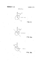
- FIG 2 shows a rotated coordinant system
- FIG. 3a shows an input polarization ellipse
- FIG. 3b shows a compensating polarization ellipse.
- FIG. 2 shows the coordinate system. If the input electrical field is E a, +1 ay, then the electric field in the rotated coordinate system is,
- the ellipticity varies as a function of the relative angles between the two elliptical waveguide sections and can vary between
- the ellipticity of this invention is variable and its polarization angle can vary between and :2
- the sense of this invention is also variable since the major axis of the elliptical waveguides can be lined up with either the x or y axis, thereby effectively delaying or advancing the x axis polarization phase length with respect to the y axis polarization phase length.
- the input wave will be elliptically polarized and by reciprocity this wave can be circularly polarized.
- An arbitrary elliptically polarized wave might have a polarization ellipse as shown in FIG. 3.
- the invention comprises two identical elliptical waveguides connected by rotary joint 12.
- the elliptical waveguides 10 are cylindrical on the exterior and each contain knurling 14 around a circumference of the guides.
- Surrounding the two elliptical waveguides and rotary joint 12 is a tubular sleeve 16.
- Allen screws 18 located in holes 20 of sleeve 16 may be screwed into holes 20 to abut knurled portions 14. This will prevent rotary motion of waveguides 10 with respect to each other.
- Access to Allen screws 18 is obtained through slots 22. With Allen screws 18 removed from holes 20, a screw driver like instrument may be inserted into holes 20 for rotating one of the elliptical waveguides with respect to the other similar to the way brakes are adjusted.
- the relative positions of the two identical elliptical waveguide sections 10 are adjusted to give the correct axial ratio.
- the two elliptical sections are then locked together and rotated until the proper compensating polarization angle is achieved.
- the waveguide cross section forthe compensator is usually made nearly circular. This fact allows the use of relationships for circular waveguide with good accuracy. Also, the nearly circular cross-section allows the compensator to be inserted in a similar circular guide without the need for special matching components since the VSWR introduced by it is small.
- the compensator is made as long as possible to assure a good match by allowing the sections to be nearly circular.
- the major and minor diameters are chosen slightly larger and smaller-than the circular guide used in the system, but different enough to provide sufficient compensation.
- the rotary joints are fabricated according to system requirements for insertion losses, pressurization, and the like.
- a device for canceling ellipticity effects of a waveguide feed system comprising:
- said two. sections are of equallength and eccentricity.
- said two sections are attached to each other and to said feed system by rotary joints.
- said device is provided with locking means for preventing relative rotation between said two sections; said device is provided with locking means for preventing relative rotation between said feed system and said two sections; whereby said two sections may be adjusted and locked with respect to each other and then be adjusted and locked ziyi h o sassttqsaiq xst mt.
Abstract
A device which compensates for polarization quality defects in circularly polarized or two-mode duplexed waveguide systems by making an elliptically polarized wave circularly polarized. Two adjacent, coaxial, elliptical waveguide sections are adjusted to give the correct axial ratio. The two elliptical waveguide sections are then locked together and rotated to arrive at the proper compensating polarization angle.
Description
UntitedStates Patent Field of Search Monag'han et al. [451 Apr. M, 1972 [s41 VARIABLE AXIAL RATIO [56] References Cited COMPENSATOR UNITED STATES PATENTS 4 2] In n ors: S ph n R- M ahan, Harvard; James D. 3,287,730 11/1966 Kerr ..333/21 RX Birch, Townsend, both of Mass. 13 Assignee: The United States of America as W t'"-."""%" "Dreamed by the secretary of the Navy Assistant Examiner-Marvin Nussbaum Attomey-R.S.Sc1asc1aetal. [22] Filed: June 21, 1971 [21] Appl.No.: 155,052 7] ABSTRACT w 1 A device which compensates for polarization quality defects 1 in'circularlypolarized-or two-mode duplexed waveguide /2 figi g systems by making an elliptically Polarized wave circularly [58] A 3 98 3 M polarized. Two adjacent, coaxial, elliptical waveguide sections are adjusted to give the correct axial ratio. The two elliptical waveguide sections are then locked together and rotated to -arrive at the proper compensating polarization angle.
5 Claims, 4 Drawing Figures PATENTEDAPR 11 m2 SHEET 1 [IF 2 FIG; 1.
I N VEN TORS.
STEPHEN R. MONAGHAN JAMES D. BIRCH I ROY MILLER ATTORNEY.
PATENTEUAPR n 1922 I 3. 656,070
sum 2 [IF 2 FIG. 2.
FIG. 30.
FIG. 3b.
' r VARIABLE AXIAL RATIO COMPENSATOR BACKGROUND OF THE INVENTION I This invention pertains to means for controlling the polarization characteristics of radio frequency electromagnetic radiation. The Pat. No. 2,930,040, dated March 22, 1960, discloses means by which linearly polarized radio frequency radiation may be transformed into radiation having arbitrarily selected polarization characteristics. However, the prior art fails to show a feed system capable of restoring elliptical polarization to circular polarization. Often, due to tolerance problems, ellipticity is introduced into an otherwise circularly polarized radio frequency radiation.
This invention compensates for polarization quality defects in circularly polarized or two-mode duplexed waveguide systems by making an elliptically polarized wave become circularly polarized.
' SUMMARY or THE INVENTION tical waveguide section, the resulting output wave .is elliptically polarized. The amount of ellipticity introduced is directly proportional to the eccentricity of the elliptical waveguide section and the phase length of the elliptical waveguide sectionQThe effect'of the elliptical section can be canceled by inserting another elliptical section in the proper orientation with the same length and eccentricity. If two such compensating sections are inserted, both the effective eccentricity and orientation of the compensating assembly can be varied by rotation of the inserted sections so as to cancel the effect of the original guide. This is true although the exact characteristic of the original guide is not known.
Previous compensators have had to be tailormade to accomrhodate the system in question, whereas this invention may be easily adjusted to accommodate a variety of systems with defects arising from various sources.
This invention can be used to restore circular polarization in an antenna feed which has become elliptical due to tolerance problems. It may be used, conversely, as a variable elliptical polarization generator in waveguide systems.
Some specific advantages of this invention are:
1. Wide waveguide bandwidth; the compensator itself is a waveguide system;
2. Ability to introduce a variable amount of ellipticity;
3. The power handling capability is as high as with an ordinary waveguide; and
4. Most importantly, the impedance mismatch introduced is small because of the small waveguide discontinuity required to produce the ellipticity.
Alternate methods of achieving variable ellipticity such-as dielectric or iris loaded waveguides could be used, but these would not have advantages 1, 3 and 4 previously stated.
BRIEF DESCRIPTION OF THE DRAWINGS FIG: 1 shows the invention as it appears in a waveguide system;
FIG 2 shows a rotated coordinant system;
FIG. 3a shows an input polarization ellipse; and
FIG. 3b shows a compensating polarization ellipse.
DESCRIPTION OF THE PREFERRED EMBODIMENT Consider the efiect of a section of elliptical waveguide upon the propagation of a circularly polarized wave. FIG. 2 shows the coordinate system. If the input electrical field is E a, +1 ay, then the electric field in the rotated coordinate system is,
prior art, such as the patent to Weil U.S.
,2 than the one polarized parallel to the y axis when both propagate in the z direction. This may be represented vectorally as,
5 a [exp( ja)} E0 rior q) v v here F1 is the transpose of EM If we now refer this vector back to the original coordinate system, Q, y the re sultant output electric field becomes,
COS 0 SIN 6 nor (4) COS 0 The resulting output wave is elliptically polarized and has both SIN 0 2s rishtet fil t sitsulet yp dm pv EI=EII+EL (5) where, E =right circularly polarized component 30. it? ef ,si wletlx slet component,
h pt 's tysfths tP lrP9h Wave is,
F F H (6) I I I which for this case reduces to,
1 SIN 2 4O r= (7) I l- SIN (0/2) Note that equation (7) is independent of 0.
If we now place a second elliptical waveguide at the output of the first one'which has the same differential phase length between the major and minor axes, but is oriented at an angle 0 with respect to the (x, y) coordinate system the resulting output can be determined in a fashion similar to that shown above. The total ellipticity of the two cascaded waveguide secsnsi s l n y 1+SIN (Cr/2) 1 SIN (0/2 Note that equation (8) is independent of 0. The resulting elliptically polarized wave is completely characterized by three parameters:
1. Ellipticity, r
2. Polarization Angle, 6
3. Sense If we now place a second elliptical waveguide at the output of the first one which has the same differential phase length, but is oriented at an angle 6' with respect to the x-y coort .system hstesukinscymutis cos 0 cos +srN 0 SIN 0) cos 0' SIN 0 SIN 0-) SIN 6COS 6 As before the left circular component is found from,
and the resulting ellipticity is,
In this case the ellipticity varies as a function of the relative angles between the two elliptical waveguide sections and can vary between The ellipticity of this invention is variable and its polarization angle can vary between and :2 The sense of this invention is also variable since the major axis of the elliptical waveguides can be lined up with either the x or y axis, thereby effectively delaying or advancing the x axis polarization phase length with respect to the y axis polarization phase length.
in the general case the input wave will be elliptically polarized and by reciprocity this wave can be circularly polarized. An arbitrary elliptically polarized wave might have a polarization ellipse as shown in FIG. 3.
The invention comprises two identical elliptical waveguides connected by rotary joint 12. The elliptical waveguides 10 are cylindrical on the exterior and each contain knurling 14 around a circumference of the guides. Surrounding the two elliptical waveguides and rotary joint 12 is a tubular sleeve 16. Allen screws 18 located in holes 20 of sleeve 16 may be screwed into holes 20 to abut knurled portions 14. This will prevent rotary motion of waveguides 10 with respect to each other. Access to Allen screws 18 is obtained through slots 22. With Allen screws 18 removed from holes 20, a screw driver like instrument may be inserted into holes 20 for rotating one of the elliptical waveguides with respect to the other similar to the way brakes are adjusted.
When elliptical waveguides 10 and tubular sleeve 16 are locked with respect to each other by Allen screws 18, the entire combination can then be rotated. This combination is connected to the remainder of the waveguide system 24 by rotary joints 26. Allen screw 28 located in hole 30 of the outer frame 32 of the waveguide system can be adjusted to abut against knurled portion 34 extending around the circumference of sheet 16. With Allen screw 28 removed from hole 30 sleeve 16 may be located with respect to outer frame 32 with a screw driver like device as previously described.
In operation, the relative positions of the two identical elliptical waveguide sections 10 are adjusted to give the correct axial ratio. The two elliptical sections are then locked together and rotated until the proper compensating polarization angle is achieved.
The waveguide cross section forthe compensator is usually made nearly circular. This fact allows the use of relationships for circular waveguide with good accuracy. Also, the nearly circular cross-section allows the compensator to be inserted in a similar circular guide without the need for special matching components since the VSWR introduced by it is small. For
each axisthe phase length I or is given by for each elliptical waveguide section.
In practice, the compensator is made as long as possible to assure a good match by allowing the sections to be nearly circular. The major and minor diameters are chosen slightly larger and smaller-than the circular guide used in the system, but different enough to provide sufficient compensation. The rotary joints are fabricated according to system requirements for insertion losses, pressurization, and the like.
v.lll at scla msaL W l. A device for canceling ellipticity effects of a waveguide feed system comprising:
two elliptical waveguide sections positioned in a waveguide system adjacent each other; said two sections being rotatable with respect to each other; said two sections being rotatable with respect to said waveguide feed system; whereby circular polarization is restored to a waveguide feed system which has become elliptically polarized.
2. The device of claim 1 wherein: said two. sections are of equallength and eccentricity. 3. The device of claim 1 wherein: said two sections are attached to each other and to said feed system by rotary joints. 4. The device of claim 1 wherein: said device is provided with locking means for preventing relative rotation between said two sections; said device is provided with locking means for preventing relative rotation between said feed system and said two sections; whereby said two sections may be adjusted and locked with respect to each other and then be adjusted and locked ziyi h o sassttqsaiq xst mt.
5. The device of claim 1 wherein: the cross section of said two sections is nearly circular.
iiii a4
Claims (5)
1. A device for canceling ellipticity effects of a waveguide feed system comprising: two elliptical waveguide sections positioned in a waveguide system adjacent each other; said two sections being rotatable with respect to each other; said two sections being rotatable with respect to said waveguide feed system; whereby circular polarization is restored to a waveguide feed system which has become elliptically polarized.
2. The device of claim 1 wherein: said two sections are of equal length and eccentricity.
3. The device of claim 1 wherein: said two sections are attached to each other and to said feed system by rotary joints.
4. The device of claim 1 wherein: said device is provided with locking means for preventing relative rotation between said two sections; said device is provided with locking means for preventing relative rotation between said feed system and said two sections; whereby said two sections may be adjusted and locked with respect to each other and then be adjusted and locked with respect to said system.
5. The device of claim 1 wherein: the cross section of said two sections is nearly circular.
Applications Claiming Priority (1)
| Application Number | Priority Date | Filing Date | Title |
|---|---|---|---|
| US15505271A | 1971-06-21 | 1971-06-21 |
Publications (1)
| Publication Number | Publication Date |
|---|---|
| US3656070A true US3656070A (en) | 1972-04-11 |
Family
ID=22553939
Family Applications (1)
| Application Number | Title | Priority Date | Filing Date |
|---|---|---|---|
| US155052A Expired - Lifetime US3656070A (en) | 1971-06-21 | 1971-06-21 | Variable axial ratio compensator |
Country Status (1)
| Country | Link |
|---|---|
| US (1) | US3656070A (en) |
Cited By (6)
| Publication number | Priority date | Publication date | Assignee | Title |
|---|---|---|---|---|
| US4549310A (en) * | 1984-03-29 | 1985-10-22 | Rca Corporation | Cross-polarization corrector for circular waveguide |
| US4717898A (en) * | 1986-06-26 | 1988-01-05 | Mitec Electronics Ltd. | Power combiner, polarizer and structure including a waveguide section rotated by a stepper motor arrangement |
| US20050158394A1 (en) * | 2000-02-28 | 2005-07-21 | Vectura Limited | Delivery of oral drugs |
| US7009464B1 (en) * | 2004-02-10 | 2006-03-07 | Lockheed Martin Corporation | Waveguide polarizer differential phase error adjustment device |
| US20060171942A1 (en) * | 2005-02-02 | 2006-08-03 | Andrew Saxon | Modified fusion molecules for treatment of allergic disease |
| US8961992B1 (en) | 2014-04-02 | 2015-02-24 | Tunitas Therapeutics, Inc. | Epsigam fusion protein |
Citations (1)
| Publication number | Priority date | Publication date | Assignee | Title |
|---|---|---|---|---|
| US3287730A (en) * | 1963-02-05 | 1966-11-22 | John L Kerr | Variable polarization antenna |
-
1971
- 1971-06-21 US US155052A patent/US3656070A/en not_active Expired - Lifetime
Patent Citations (1)
| Publication number | Priority date | Publication date | Assignee | Title |
|---|---|---|---|---|
| US3287730A (en) * | 1963-02-05 | 1966-11-22 | John L Kerr | Variable polarization antenna |
Cited By (10)
| Publication number | Priority date | Publication date | Assignee | Title |
|---|---|---|---|---|
| US4549310A (en) * | 1984-03-29 | 1985-10-22 | Rca Corporation | Cross-polarization corrector for circular waveguide |
| US4717898A (en) * | 1986-06-26 | 1988-01-05 | Mitec Electronics Ltd. | Power combiner, polarizer and structure including a waveguide section rotated by a stepper motor arrangement |
| US20050158394A1 (en) * | 2000-02-28 | 2005-07-21 | Vectura Limited | Delivery of oral drugs |
| EP1941868A2 (en) | 2000-02-28 | 2008-07-09 | PharmaKodex Limited | Improvements in or relating to the delivery of oral drugs |
| US7009464B1 (en) * | 2004-02-10 | 2006-03-07 | Lockheed Martin Corporation | Waveguide polarizer differential phase error adjustment device |
| US20060171942A1 (en) * | 2005-02-02 | 2006-08-03 | Andrew Saxon | Modified fusion molecules for treatment of allergic disease |
| US7488804B2 (en) | 2005-02-02 | 2009-02-10 | The Regents Of The University Of California | Modified fusion molecules for treatment of allergic disease |
| US20090136493A1 (en) * | 2005-02-02 | 2009-05-28 | Andrew Saxon | Modified fusion molecules for treatment of allergic disease |
| US8961992B1 (en) | 2014-04-02 | 2015-02-24 | Tunitas Therapeutics, Inc. | Epsigam fusion protein |
| US9109030B1 (en) | 2014-04-02 | 2015-08-18 | Tunitas Therapeutics, Inc. | Epsigam fusion protein |
Similar Documents
| Publication | Publication Date | Title |
|---|---|---|
| US4141015A (en) | Conical horn antenna having a mode generator | |
| Fox | An adjustable wave-guide phase changer | |
| US2599753A (en) | Wave guide phase shifter | |
| US4353041A (en) | Selectable linear or circular polarization network | |
| US11367935B2 (en) | Microwave circular polarizer | |
| US2858512A (en) | Apparatus for varying the phase in waveguide systems | |
| US9257734B2 (en) | Compact amplitude and phase trimmer | |
| US2713151A (en) | Two channel rotary joint | |
| US3215957A (en) | Variable polarization for microwaves | |
| US3656070A (en) | Variable axial ratio compensator | |
| US5576668A (en) | Tandem circular polarizer | |
| US3287729A (en) | Polarisers for very high frequency electro-magnetic waves | |
| US2542185A (en) | Rotatable attenuator without phase shift | |
| GB818447A (en) | Microwave antenna feed for circular polarization | |
| US3588751A (en) | High power microwave power divider | |
| US3914764A (en) | Apparatus for reducing cross coupling between orthogonal polarizations in satellite communication systems | |
| US3728643A (en) | Apparatus for transforming nonorthogonal elliptically polarized waves into orthogonal linearly polarized waves | |
| US3166725A (en) | Broadband tuning transformer permitting independent matching at adjacent frequencies | |
| US3096474A (en) | Microwave frequency converter | |
| RU2650719C1 (en) | Separator of orthogonal polarized waves | |
| JP3011111B2 (en) | Broadband antenna feeder | |
| US2736865A (en) | Adjustable phase-shifting device for high-frequency alternating voltages | |
| SU1830560A1 (en) | Separator of orthogonally polarized waves | |
| GB960494A (en) | Improvements in or relating to polarisers for very high frequency electro-magnetic waves | |
| US2886785A (en) | Wave transducer |