US4811921A - Cyclic control stick - Google Patents
Cyclic control stick Download PDFInfo
- Publication number
- US4811921A US4811921A US07/064,988 US6498887A US4811921A US 4811921 A US4811921 A US 4811921A US 6498887 A US6498887 A US 6498887A US 4811921 A US4811921 A US 4811921A
- Authority
- US
- United States
- Prior art keywords
- control stick
- adapter housing
- stalk
- cyclic control
- grip
- Prior art date
- Legal status (The legal status is an assumption and is not a legal conclusion. Google has not performed a legal analysis and makes no representation as to the accuracy of the status listed.)
- Expired - Fee Related
Links
Images

Classifications
-
- B—PERFORMING OPERATIONS; TRANSPORTING
- B64—AIRCRAFT; AVIATION; COSMONAUTICS
- B64C—AEROPLANES; HELICOPTERS
- B64C27/00—Rotorcraft; Rotors peculiar thereto
- B64C27/54—Mechanisms for controlling blade adjustment or movement relative to rotor head, e.g. lag-lead movement
- B64C27/56—Mechanisms for controlling blade adjustment or movement relative to rotor head, e.g. lag-lead movement characterised by the control initiating means, e.g. manually actuated
-
- B—PERFORMING OPERATIONS; TRANSPORTING
- B64—AIRCRAFT; AVIATION; COSMONAUTICS
- B64C—AEROPLANES; HELICOPTERS
- B64C13/00—Control systems or transmitting systems for actuating flying-control surfaces, lift-increasing flaps, air brakes, or spoilers
- B64C13/02—Initiating means
- B64C13/04—Initiating means actuated personally
- B64C13/042—Initiating means actuated personally operated by hand
- B64C13/0421—Initiating means actuated personally operated by hand control sticks for primary flight controls
-
- Y—GENERAL TAGGING OF NEW TECHNOLOGICAL DEVELOPMENTS; GENERAL TAGGING OF CROSS-SECTIONAL TECHNOLOGIES SPANNING OVER SEVERAL SECTIONS OF THE IPC; TECHNICAL SUBJECTS COVERED BY FORMER USPC CROSS-REFERENCE ART COLLECTIONS [XRACs] AND DIGESTS
- Y10—TECHNICAL SUBJECTS COVERED BY FORMER USPC
- Y10T—TECHNICAL SUBJECTS COVERED BY FORMER US CLASSIFICATION
- Y10T74/00—Machine element or mechanism
- Y10T74/20—Control lever and linkage systems
- Y10T74/20396—Hand operated
-
- Y—GENERAL TAGGING OF NEW TECHNOLOGICAL DEVELOPMENTS; GENERAL TAGGING OF CROSS-SECTIONAL TECHNOLOGIES SPANNING OVER SEVERAL SECTIONS OF THE IPC; TECHNICAL SUBJECTS COVERED BY FORMER USPC CROSS-REFERENCE ART COLLECTIONS [XRACs] AND DIGESTS
- Y10—TECHNICAL SUBJECTS COVERED BY FORMER USPC
- Y10T—TECHNICAL SUBJECTS COVERED BY FORMER US CLASSIFICATION
- Y10T74/00—Machine element or mechanism
- Y10T74/20—Control lever and linkage systems
- Y10T74/20576—Elements
- Y10T74/20582—Levers
- Y10T74/20612—Hand
-
- Y—GENERAL TAGGING OF NEW TECHNOLOGICAL DEVELOPMENTS; GENERAL TAGGING OF CROSS-SECTIONAL TECHNOLOGIES SPANNING OVER SEVERAL SECTIONS OF THE IPC; TECHNICAL SUBJECTS COVERED BY FORMER USPC CROSS-REFERENCE ART COLLECTIONS [XRACs] AND DIGESTS
- Y10—TECHNICAL SUBJECTS COVERED BY FORMER USPC
- Y10T—TECHNICAL SUBJECTS COVERED BY FORMER US CLASSIFICATION
- Y10T74/00—Machine element or mechanism
- Y10T74/20—Control lever and linkage systems
- Y10T74/20576—Elements
- Y10T74/20732—Handles
- Y10T74/2078—Handle bars
- Y10T74/20828—Handholds and grips
-
- Y—GENERAL TAGGING OF NEW TECHNOLOGICAL DEVELOPMENTS; GENERAL TAGGING OF CROSS-SECTIONAL TECHNOLOGIES SPANNING OVER SEVERAL SECTIONS OF THE IPC; TECHNICAL SUBJECTS COVERED BY FORMER USPC CROSS-REFERENCE ART COLLECTIONS [XRACs] AND DIGESTS
- Y10—TECHNICAL SUBJECTS COVERED BY FORMER USPC
- Y10T—TECHNICAL SUBJECTS COVERED BY FORMER US CLASSIFICATION
- Y10T74/00—Machine element or mechanism
- Y10T74/20—Control lever and linkage systems
- Y10T74/20576—Elements
- Y10T74/20732—Handles
- Y10T74/20834—Hand wheels
- Y10T74/2087—Rim grips and covers
Definitions
- This invention relates in general to cyclic control sticks of the type commonly used in helicopters, and more particularly to a cyclic control stick which is configured to reduce the safety hazards associated therewith by, among other things, breaking away upon exertion of an impact load thereon of a magnitude which could occur in crashes or abnormally sudden stops.
- Conventional cyclic control sticks are formed of rigid metal tubing and make no provisions for absorbing impact energy or otherwise improving the safety of a helicopter crewmen's environment.
- prior art cyclic controls ticks also lack height adjustment capabilities and thus make no provisions for crewmen of different sizes.
- a new and improved cyclic control stick of the type used in helicopters is disclosed for reducing the safety hazards associated with such a device and for facilitating the use thereof.
- the cyclic control stick of the present invention includes an especially configured coupling assembly having an adapter housing for attachment of the cyclic control stick to the control input structure of the helicopter, and having a breakaway stalk in which the tubular standard and grip portions of the cyclic control stick are supported.
- the coupling assembly further includes an energy absorbing means and a slip joint means which interconnect the adapter housing and the breakaway stalk.
- the energy absorbing means maintains the interconnection of the adapter housing and the breakaway stalk when downwardly applied impact forces on the cyclic control stick are below a predetermined value and/or are applied for a momentary time duration. Maintaining of the interconnection under those conditions prevents unwanted separation of the breakaway stalk, tubular standard and grip from the adapter housing in non-emergency, or non-life threatening situations. In the event of the application of downwardly directed impact forces on the cyclic control stick of a magnitude greater than the predetermined value and for longer than the momentary time duration, the energy absorbing capabilities of the energy absorbing means will be exceeded. When exceeded in this manner, the interconnection of the breakaway stalk, the tubular standard, and grip will no long exist and the slip-joint means will cause the breakaway stalk, the tubular standard are the grip to fall freely away from the adapter housing.
- the energy absorbing means is of a configuration which may be referred to as a wire-bender energy absorber.
- a single length of wire is formed with a loop intermediate its opposite ends which is looped under a projecting stud provided on the breakaway stalk of the cyclic control stick.
- the opposite ends of the wire are wrapped around a bushing which is mounted for free rotation on a shaft that is carried in the adapter housing.
- the stud provided in the breakaway stack will transmit the impact force to the wire by pulling downwardly on the loop thereof.
- the impact forces are below the predetermined value and/or are of momentary duration, the wrapped around, or coiled, ends of the wire will not be pulled into a straight enough condition to allow them to become disengaged from the rotatable bushing of the adapter housing.
- the impact forces are greater than the predetermined value and are applied for a time which is longer than the momentary duration, the coiled ends of the wire will be straightened and thus pulled out of engagement with the bushing of the adapter housing.
- the energy absorbing means is of a configuration which may be referred to as a tab-bender energy absorber.
- the tab-bender structure includes a load resistor which is attached to the adapter housing and has a plurality of tabs extending normally therefrom toward the breakaway stalk. The extending tabs are arranged in vertical alignment and are spaced apart with respect to each other. A bender plate is attached to the breakaway stalk so as to extend therefrom in overlaying relationship with respect to the uppermost one of the tabs of the load resistor.
- the breakaway stalk, tubular standard and grip When downwardly directed impact forces are applied to the cyclic control stick, the breakaway stalk, tubular standard and grip will move downwardly and thereby move the bender plate downwardly into sequential bending engagement with the extending tabs of the load resistor. If the impact forces are below the predetermined value and/or are of a momentary time duration, less than all of the extending tabs of the load resistor will be bent out of the movement path of the bender plate. This will, of course, result in lowering of the breakaway stalk, tubular standard and the grip relative to the adapter housing but the interconnection of the breakaway stalk and the adapter housing will be maintained so that the cyclic control stick remains operable.
- a special bearing arrangement is preferably used to provide the slip joint means of the coupling assembly.
- the special bearing arrangement allows the free separation of the breakaway stalk from the adapter housing in a movement path which is parallel to the plane of the interconnection, i.e. in a shearing-like movement.
- the special bearing arrangement includes a wedge-shaped race structure with bearings loaded in opposing directions on that race to prevent separation of the breakaway stalk from the adapter housing in a movement path that is normal with respect to the shear-like movement path.
- the cyclic control stick is provided with a crushable pad means on the top of the grip which absorbs impact energy and enlarges the contact area of the grip to further reduce the safety hazards of the control stick.
- Still another safety consideration is the in-use location of the grip of the cyclic control stick.
- the grip should be as far away from the head and upper body of the helicopter pilot as possible without sacrificing pilot comfort and the ability to properly use the cyclic control stick. Since various factors such a pilot size, arm length and the like all enter into achieving optimum positioning, the cyclic control stick of the present invention includes a height adjustment means whereby the tubular standard, and thus the grip, may be adjusted relative to the breakaway stalk.
- Another object of the present invention is to provide a new and improved cyclic control stick wherein the upstanding portions of the control stick will breakaway in the event of the helicopter pilot being thrown into contact therewith as a result of a crash or other abnormally abrupt stop.
- Another object of the present invention is to provide a new and improved cyclic control stick of the above described character wherein the breakaway feature is provided by an energy absorbing means and a slip joint means which interact to prevent breaking away upon the application of impact loads below a predetermined value and/or of a momentary time duration, and accomplishes the breaking away when the impact loading exceeds those factors.
- Another object of the present invention is to provide a new and improved cyclic control stick of the above described type which further includes a crushable pad on the top of the grip of the cyclic control stick to absorb impact energy and enlarge the contact area of the grip.
- Still another object of the present invention is to provide a new and improved cyclic control stick of the type used in helicopters wherein the cyclic control stick includes means for adjusting the height thereof to locate the grip as far away from the pilot as possible without sacrificing pilot comfort or the ability to properly use the control stick.
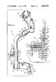
- FIG. 1 is a side view of the cyclic control stick of the present invention which is partially broken away to show some of the various features thereof.
- FIG. 2 is an enlarged fragmentary sectional view taken along the line 2--2 of FIG. 1.
- FIG. 3 is a fragmentary sectional view taken along the line 3--3 of FIG. 2.
- FIG. 4 is an enlarged fragmentary sectional view taken along the line 4--4 of FIG. 1.
- FIG. 5 is a fragmentary sectional view taken along the line 5--5 of FIG. 4.
- FIG. 6 is a fragmentary sectional veiw similar to FIG. 4 and showing an alternate embodiment of the present invention.
- FIG. 7 is a fragmentary sectional veiw taken along the line 7--7 of FIG. 6.
- FIG. 1 shows the cyclic control stick of the present invention which is indicated in its entirety by the reference numeral 10.
- the cyclic control stick 10 includes the major components of a grip 12, a tubular standard 14 and a coupling assembly 16.
- the grip 12 which is illustrated in FIG. 1 is intended to be representative of all such grips and the present invention is not intended to be limited to the particular configuration shown. However as is typical in all grips, the grip 12 has a top end 18 which forms what may be described as the contact area into which the helicopter pilot's head, neck or torso may be violently thrown in the event of a crash or other abnormally sudden and abrupt stop.
- a crushable pad means 20 is mounted on the contact area 18.
- the pad means 20 preferably includes a pad body 21 of crushable deformable material such as polyurethane foam having a density of about 5.0 pounds per cubic foot.
- the pad body 21 is encased within a protective cover 22, such as of nylon mesh, which protects the pad body 21 from wear and helps hold it in place in the event of impact.
- the crushable pad means 20 may be bonded to the top of the grip 12 by means of a suitable adhesive.
- the grip 12 further includes a tubular boss 24 which extends from its lower end for mounting on the upper end 26 of the tubular standard 14.
- the upper end 26 of the standard 14 is disposed in the bore 27 of the boss 24, and a fastener means, such as the illustrated bolt-nut assembly 28, is located in suitably aligned holes to demountably hold the grip 12 on the standard 14.
- the standard 14 is of tubular configuration to allow passage of electrical conductors (not shown), from the grip controls through the bore 29 of the standard to the helicopter equipment that is controllable from the grip.
- the actual length and curved shape of the standard 14 are optional.
- the coupling assembly 16 includes a breakaway stalk body 30 having an upstanding sleeve portion 32 which defines an upwardly opening axial bore 34.
- the lower end 36 of the tubular standard 14 is slideably mounted in the axial bore 34 of the sleeve 32, and a manually operably latching means 38 is provided to selectively and adjustably hold the standard 14 in desired telescopically extending positions.
- This provides the cyclic control stick 10 of the present invention with a heigh adjustment for locating the top of the grip 12 as far away from the helicopter pilot as possible without compromising pilot comfort and the ability for proper use of the cyclic control stick 10.
- an elongated rack 40 is fixedly mounted on the lower end 36 of the tubular standard 14 such as by the rivets 41 so that the rack extends axially of the standard.
- a series of spaced apart holes 42 are formed in the rack 40 along the length thereof for selective engagement by the latching means 38.
- the upstanding sleeve portion 32 of the breakaway stalk body 30 has an extending protrusion 44 which defines an elongated groove 45 that opens inwardly into the bore 34 of the sleeve 32.
- the elongated rack 40 of the tubular standard 14 is disposed so as to be slideably moveable in the groove 45.
- An externally threaded boss 46 extends normally from the protrusion 44 of the sleeve and defines a bore 48 which opens into the groove 45 and has a suitable bushing mounted therein.
- the boss 46 further defines a counterbore 49 which opens onto the extending end of the boss 46.
- An internally threaded nut 50 is mounted on the boss 46 and has a suitable bushing mounted in an opening 52 formed axially through its otherwise closed end 54.
- a slide pin 56 having a front end 57 and a back end 58, is mounted for movement in the bushing of the bore 48 of the boss 46 and the bushing of the opening formed in the nut 50.
- a compression spring 60 is disposed in the counterbore 49 of the boss 46 for biasing the slide pin 56 to an extending position wherein its front end 57 extends into a selected one of the holes 42 of the rack 40.
- the back end 58 of the slide pin 56 extends axially from the closed end 54 of the nut 50 and is eccentrically connected by means of a suitable pin 62 to a manually operable cam lever 64.
- the cam lever 64 includes a bifurcated cam 66 of circular configuration which is held in bearing engagement with the closed end 54 of the nut 50 by action of the compression spring 60.
- the tubular standard 14 is telescopically adjustable in the upstanding sleeve 32 of the breakaway stalk body 30.
- an elongated groove 70 is formed in one side of the rack 40 that is mounted on the tubular standard 14.
- the groove 70 is closed at its top and bottom ends as indicated at 71 and 72, respectively, to serve as stops.
- a set screw 74 is threadingly carried in a bore 76 formed in the side of the protrusion 44 of the sleeve 32 of the breakaway stalk body 30. As shown in FIG. 2, the set screw 74 protrudes into the groove 70 of the rack 40 and will therefore limit both the up and down movements of the standard 14 in the sleeve 32.
- the breakaway stalk body 30 includes a tongue 78, in addition to the upstanding sleeve 32
- the tongue 78 extends normally from the lower end of the sleeve 32 in a direction which is diametrically opposed to the protrusion 44 of the sleeve.
- the coupling assembly 16 further includes an adapter housing 80.
- the stalk body 30 is connected to the adapter housing for separation upon the exertion of an impact force on the top end of the grip 12 of the cyclic control stick 10.
- the adapter housing also provides means for connection of the cyclic control stick 10 to the control input mechanism of the helicopter, with the input mechanism being indicated by the reference numeral 82 in FIG. 1.
- the adapter housing 80 is provided with a mounting means 84 which is shown in the form of a shaft which is carried in a bore 85 provided in one end of the adapter housing.
- the shaft 84 is mounted in the bore 85 by means of a suitable bolt 86 and depends angularly from the adapter housing 80 for connection to the helicopter input mechanism 82 such as by means of the illustrated bolt 87.
- the opposite end of the adapter housing 80 is bifurcated to define an open cavity 90 between a pair of arms 92 and 94.
- the housing 80 is a cover 96 mounted thereon which closes the top of the cavity 90 with the cavity being otherwise open, i.e. both laterally and downwardly.
- the tongue 78 of the breakaway stalk body 30 is normally disposed so as to extend into the cavity 90 through the lateral opening thereof, and a slip joint means 98 and an energy absorbing means 100 combine to interconnect the stalk body 30 and the adapter housing 80 and to allow separation in response to the aforementioned impact forces.
- the tongue 78 is formed with one side surface 102 which is planar and an opposed side surface which has a transversely extending substantially V-shaped groove 104 formed therein.
- a first bearing race 106 is affixed, such as by means of a suitable adhesive, to the planar surface 102 of the tongue 78, and a pair of bearing races 107 and 108 are each similarly affixed to different ones of the diverging surfaces of the V-shaped groove 104.
- a wedge shaped bearing race 110 is interposed between the inwardly facing surface of the arm 94 and the V-shaped groove 104 of the tongue 78.
- a dowel 111 extends from the wedge-shaped race 110 into a channel 112 that is transversely formed in the inwardly facing surface of the arm 94.
- the dowel-channel arrangement prevents lateral movements of the wedge-shaped race 110 and allows it to move along the length of the channel 112 for reasons which will be hereinafter described.
- a pair of caged roller bearings 114 and 116 are each interposed between a different one of the converging bearing race surfaces of the wedge-shaped race 110 and the races 107 and 108 that are mounted in the V-shaped groove 104 of the tongue 78.
- An adjustable planar plate defining a bearing race 118 is interposed between the arm 92 and the race 106 that is mounted on the planar surface 102 of the tongue 78.
- the adjustable race 118 has a projecting dowel 120 which extends normally therefrom into a channel 122 that is formed transversely in the inwardly facing surface of the arm 92.
- A is the case with the wedge-shaped bearing race 110, the dowel-channel arrangement of the adjustable bearing race 118 prevents lateral movements of the race but allows it to move along the length of the channel 122.
- a caged roller bearing 124 is interposed between the adjustable bearing race 118 and the race 106 that is fixed on the planar surface 102 of the tongue 78.
- the adjustable bearing race 118 In addition to the free movement of the adjustable bearing race 118 in a direction transverse with respect to the extending length of the arm 92, the adjustable bearing race 118 is movable toward and away from the planar surface 102 of the tongue 78. Such movement of the adjustable bearing race 118 is controlled by a plurality of adjustment screws 126 which are threadingly carried in suitable bores formed in the arm 92 of the adapter housing 80. The adjustment screws 126 extend into bearing engagement with the adjustable bearing race 118 for adjustable positioning thereof so that the race 118 will exert a desired load on the bearings 114, 116 and 124.
- the hereinbefore mentioned cover 96 which closes the upper end of the cavity 90 defined between the arms 92 and 94, prevents the breakaway stalk body 30 from being pulled upwardly from between the arms 92 and 94. But, the bottom end of the cavity 90 is open as indicated in FIG. 5, and the breakaway body 30 is free to fall out of the bottom of that cavity 90 by virtue of the hereinbefore described bearing arrangement of the slip-joint means 98.
- the above mentioned energy absorbing means 100 is used to keep the breakaway stalk body 30 from falling out of the open bottom of the cavity 90 of the adapter housing in the absence of impact forces of predetermined magnitude and time duration.
- the energy absorbing means 100 which may be referred to as a wire-bender energy absorbing device, is shown in FIGS. 4 and 5.
- the wire-bender device 100 includes a shaft 130 which has its opposite ends disposed in suitably aligned openings formed in the arms 92 and 94 so that the shaft 130 extends transversely across the cavity 90 proximate the inwardly disposed closed end thereof.
- a suitable roller bushing 132 is mounted on the shaft 130 for rotation about the longitudinal axis thereof.
- a load resistor in the preferred form of a single length of wire 133 such as music wire, is formed with a loop 134 intermediate its opposite ends, and its opposite ends 136 and 138 are wrapped around the roller bushing 132 to form coils.
- a stud 140 extends normally from the distal end 142 of the tongue 78 of the breakaway stalk body 30 into the loop 134 of the wire.
- the stalk body 30 is supported and connected to the adapter housing 80 by virtue of the stud 140 and the loop 134 of the wire 133.
- FIGS. 6 and 7 wherein a modification of the cyclic controls tick of the present invention is shown as including a second embodiment of the energy absorbing means in the form of a tab-bender structure which is indicated generally by the reference numeral 144.
- the above described slip-joint means 98 is used in this embodiment for interconnecting a modified breakaway stalk body 30A to a modified adapter housing 80A.
- the stalk body 30A is provided with a bender plate 146 that is mounted, such as by means of the illustrated screw 147, in a notch 148 which is formed for that purpose in the top surface of the tongue 78A.
- the tongue 78A has a cover 149 mounted thereon for closing the bottom end of the cavity 90 without interfering with the desired separation of the stalk body 30A from the adapter housing 80A.
- the bender plate 146 extends normally from the distal end 142A of the tongue 78A into the open space provided at the innermost end of the cavity 90 defined by the adapter housing 80A.
- a load resistor means 150 is attached, such as by the illustrated screws 151, and 157 the surface 152 of the adapter housing 80A which defines the inner closed end of the cavity 90.
- the load resistor means 150 includes a flat plate 154 from which a plurality (three shown) of tabs 156 extend normally toward the distal end 142A of the tongue 78A of the stalk body 30A. As shown, the extending tabs 156 are arranged in vertically spaced alignment with each other so that impact forces will result in downward movement of the bender plate 146 into sequentially deflecting engagement with the tabs 156.
- the tab-bender energy absorber means 144 will react to impact forces much in the same manner as the hereinbefore described wire-bender energy absorber 100. In other words, impact forces below a predetermined value and/or of a momentary duration will not result in full separation, but forces which meet or exceed those built-in safety factors will result in separation.
- Dynamic testing of the cyclic control stick 10 of the present invention has indicated that a substantial reduction in the severity of serious injuries an d fatalities can be expected in comparison to the cyclic control sticks currently being used in, for example, the UH-60A Black Hawk helicopter.
- Head injury severity which is measured by a "HIC” value (head injury criterion) showed a reduction to 568 of the cyclic control stick 10 in comparison to a HIC value of 1026 for the control stick currently being used in the UH-60A Black Hawk helicopter.
- the predetermined impact force value at which separation of the cyclic control stick 10 will occur may be altered, a force of approximately 125 pounds exerted on the energy absorber means appears to be a satisfactory comprise between maintaining the operability of the cyclic control stick in non-like threatening situations and reducing the seriousness of injuries or fatalities in life-threatening situations.
Abstract
Description
Claims (22)
Priority Applications (1)
| Application Number | Priority Date | Filing Date | Title |
|---|---|---|---|
| US07/064,988 US4811921A (en) | 1987-06-22 | 1987-06-22 | Cyclic control stick |
Applications Claiming Priority (1)
| Application Number | Priority Date | Filing Date | Title |
|---|---|---|---|
| US07/064,988 US4811921A (en) | 1987-06-22 | 1987-06-22 | Cyclic control stick |
Publications (1)
| Publication Number | Publication Date |
|---|---|
| US4811921A true US4811921A (en) | 1989-03-14 |
Family
ID=22059591
Family Applications (1)
| Application Number | Title | Priority Date | Filing Date |
|---|---|---|---|
| US07/064,988 Expired - Fee Related US4811921A (en) | 1987-06-22 | 1987-06-22 | Cyclic control stick |
Country Status (1)
| Country | Link |
|---|---|
| US (1) | US4811921A (en) |
Cited By (27)
| Publication number | Priority date | Publication date | Assignee | Title |
|---|---|---|---|---|
| US5022283A (en) * | 1990-03-26 | 1991-06-11 | Deslandes Mark R | Turn signal auxiliary lever apparatus |
| US5165301A (en) * | 1991-04-22 | 1992-11-24 | Jeshurun David R | Steering members for bicycles |
| WO1994019238A2 (en) * | 1993-02-24 | 1994-09-01 | Altair Corporation | Control system for aircraft |
| US5427336A (en) * | 1993-02-24 | 1995-06-27 | Haggerty; Matthew K. | Dual control mechanism for aircraft |
| US5431361A (en) * | 1993-12-02 | 1995-07-11 | United Technologies Corporation | Crashworthy cyclic control stick system for a helicopter |
| US5472156A (en) * | 1994-03-28 | 1995-12-05 | The United States Of America As Represented By The Secretary Of The Army | Air combat collective control head |
| US5527004A (en) * | 1993-02-24 | 1996-06-18 | Helix Air, Inc. | Control system for aircraft |
| US5769363A (en) * | 1995-10-31 | 1998-06-23 | The Cessna Aircraft Company | Aircraft adjustable control stick |
| US6152239A (en) * | 1999-01-25 | 2000-11-28 | Caterpillar Inc. | Ergonomic electronic hand control for a motor grader |
| US6360627B1 (en) * | 2000-06-22 | 2002-03-26 | Daimlerchrysler Corporation | Offset transmission shift lever arrangement |
| US20050195168A1 (en) * | 1995-09-27 | 2005-09-08 | Rosenberg Louis B. | Power management for interface devices applying forces |
| US20060021459A1 (en) * | 2004-07-30 | 2006-02-02 | Buckingham David G | Offset transmission shift lever and isolator arrangement |
| US7000497B1 (en) | 2002-04-22 | 2006-02-21 | Harry Edward Campbell | Selectively positionable gearshift and method |
| US20060109256A1 (en) * | 2004-10-08 | 2006-05-25 | Immersion Corporation, A Delaware Corporation | Haptic feedback for button and scrolling action simulation in touch input devices |
| US20060194180A1 (en) * | 1996-09-06 | 2006-08-31 | Bevirt Joeben | Hemispherical high bandwidth mechanical interface for computer systems |
| US20060243854A1 (en) * | 2005-02-24 | 2006-11-02 | Sikorsky Aircraft Corporation | Energy absorbing airframe for a vertical lift vehicle |
| US20060267932A1 (en) * | 1994-07-12 | 2006-11-30 | Immersion Corporation | Force feedback device including coupling device |
| US7446752B2 (en) | 1999-09-28 | 2008-11-04 | Immersion Corporation | Controlling haptic sensations for vibrotactile feedback interface devices |
| US20090188342A1 (en) * | 2008-01-30 | 2009-07-30 | Cymbal William D | Adjustable steering column assembly with break-away lever |
| US20150259065A1 (en) * | 2014-03-12 | 2015-09-17 | Bell Helicopter Textron Inc. | Retention systems for rotorcraft pedal assemblies |
| US10198024B2 (en) | 2016-12-29 | 2019-02-05 | David S. Fryer | Ergonomic gear shift grip adjuster |
| US10330190B2 (en) * | 2016-03-23 | 2019-06-25 | Fca Italy S.P.A. | Gear lever |
| US20190263504A1 (en) * | 2018-02-26 | 2019-08-29 | Bell Helicopter Textron Inc. | Adjustable Cyclic Stick |
| US10591948B1 (en) | 2018-08-30 | 2020-03-17 | Essex Industries, Inc. | Collective control system for a rotorcraft |
| USD897929S1 (en) | 2018-11-29 | 2020-10-06 | Essex Industries, Inc. | Controller for rotorcraft |
| US11084570B2 (en) | 2016-04-22 | 2021-08-10 | Ratier-Figeac Sas | Control stick pivot |
| EP3885253A1 (en) * | 2020-03-25 | 2021-09-29 | Wittenstein Se | Plinth system |
Citations (11)
| Publication number | Priority date | Publication date | Assignee | Title |
|---|---|---|---|---|
| US2075110A (en) * | 1935-03-19 | 1937-03-30 | Eugene S Starrett | Extensible steering wheel post |
| US2827801A (en) * | 1954-01-20 | 1958-03-25 | Gen Motors Corp | Automotive steering device |
| US2910887A (en) * | 1956-08-08 | 1959-11-03 | James D H Helms | Collapsible and adjustable steering column |
| US3071023A (en) * | 1960-02-09 | 1963-01-01 | Happich Gmbh Gebr | Non-injurious resilient actuating knobs for use in automotive vehicles and the like |
| US3172683A (en) * | 1961-12-19 | 1965-03-09 | Antini Pasquale I D | Safety cushion for vehicles |
| US3823618A (en) * | 1972-03-28 | 1974-07-16 | Peugeot & Renault | Steering wheels for automobile vehicles |
| US3851542A (en) * | 1972-05-02 | 1974-12-03 | Cam Gears Ltd | Collapsible steering columns |
| US3911759A (en) * | 1972-07-18 | 1975-10-14 | Toyota Motor Co Ltd | Steering apparatus for vehicles |
| US3936015A (en) * | 1974-06-28 | 1976-02-03 | United Technologies Corporation | Retractable collective pitch stick |
| US3960031A (en) * | 1974-09-11 | 1976-06-01 | Regie Nationale Des Usines Renault | Collapsible steering columns |
| US4655416A (en) * | 1985-05-23 | 1987-04-07 | United Technologies Corporation | Cyclic stick construction for crashworthy seat cockpit |
-
1987
- 1987-06-22 US US07/064,988 patent/US4811921A/en not_active Expired - Fee Related
Patent Citations (11)
| Publication number | Priority date | Publication date | Assignee | Title |
|---|---|---|---|---|
| US2075110A (en) * | 1935-03-19 | 1937-03-30 | Eugene S Starrett | Extensible steering wheel post |
| US2827801A (en) * | 1954-01-20 | 1958-03-25 | Gen Motors Corp | Automotive steering device |
| US2910887A (en) * | 1956-08-08 | 1959-11-03 | James D H Helms | Collapsible and adjustable steering column |
| US3071023A (en) * | 1960-02-09 | 1963-01-01 | Happich Gmbh Gebr | Non-injurious resilient actuating knobs for use in automotive vehicles and the like |
| US3172683A (en) * | 1961-12-19 | 1965-03-09 | Antini Pasquale I D | Safety cushion for vehicles |
| US3823618A (en) * | 1972-03-28 | 1974-07-16 | Peugeot & Renault | Steering wheels for automobile vehicles |
| US3851542A (en) * | 1972-05-02 | 1974-12-03 | Cam Gears Ltd | Collapsible steering columns |
| US3911759A (en) * | 1972-07-18 | 1975-10-14 | Toyota Motor Co Ltd | Steering apparatus for vehicles |
| US3936015A (en) * | 1974-06-28 | 1976-02-03 | United Technologies Corporation | Retractable collective pitch stick |
| US3960031A (en) * | 1974-09-11 | 1976-06-01 | Regie Nationale Des Usines Renault | Collapsible steering columns |
| US4655416A (en) * | 1985-05-23 | 1987-04-07 | United Technologies Corporation | Cyclic stick construction for crashworthy seat cockpit |
Cited By (42)
| Publication number | Priority date | Publication date | Assignee | Title |
|---|---|---|---|---|
| US5022283A (en) * | 1990-03-26 | 1991-06-11 | Deslandes Mark R | Turn signal auxiliary lever apparatus |
| US5165301A (en) * | 1991-04-22 | 1992-11-24 | Jeshurun David R | Steering members for bicycles |
| WO1994019238A2 (en) * | 1993-02-24 | 1994-09-01 | Altair Corporation | Control system for aircraft |
| WO1994019238A3 (en) * | 1993-02-24 | 1994-12-08 | Altair Corp | Control system for aircraft |
| US5427336A (en) * | 1993-02-24 | 1995-06-27 | Haggerty; Matthew K. | Dual control mechanism for aircraft |
| US5527004A (en) * | 1993-02-24 | 1996-06-18 | Helix Air, Inc. | Control system for aircraft |
| AU690117B2 (en) * | 1993-02-24 | 1998-04-23 | Altair Corporation | Control system for aircraft |
| US5431361A (en) * | 1993-12-02 | 1995-07-11 | United Technologies Corporation | Crashworthy cyclic control stick system for a helicopter |
| US5472156A (en) * | 1994-03-28 | 1995-12-05 | The United States Of America As Represented By The Secretary Of The Army | Air combat collective control head |
| US20060267932A1 (en) * | 1994-07-12 | 2006-11-30 | Immersion Corporation | Force feedback device including coupling device |
| US20050195168A1 (en) * | 1995-09-27 | 2005-09-08 | Rosenberg Louis B. | Power management for interface devices applying forces |
| US7439951B2 (en) * | 1995-09-27 | 2008-10-21 | Immersion Corporation | Power management for interface devices applying forces |
| US5769363A (en) * | 1995-10-31 | 1998-06-23 | The Cessna Aircraft Company | Aircraft adjustable control stick |
| US20060194180A1 (en) * | 1996-09-06 | 2006-08-31 | Bevirt Joeben | Hemispherical high bandwidth mechanical interface for computer systems |
| US7500853B2 (en) | 1996-09-06 | 2009-03-10 | Immersion Corporation | Mechanical interface for a computer system |
| US6152239A (en) * | 1999-01-25 | 2000-11-28 | Caterpillar Inc. | Ergonomic electronic hand control for a motor grader |
| US7446752B2 (en) | 1999-09-28 | 2008-11-04 | Immersion Corporation | Controlling haptic sensations for vibrotactile feedback interface devices |
| US9492847B2 (en) | 1999-09-28 | 2016-11-15 | Immersion Corporation | Controlling haptic sensations for vibrotactile feedback interface devices |
| US20090278819A1 (en) * | 1999-09-28 | 2009-11-12 | Immersion Corporation | Controlling Haptic Sensations For Vibrotactile Feedback Interface Devices |
| US6360627B1 (en) * | 2000-06-22 | 2002-03-26 | Daimlerchrysler Corporation | Offset transmission shift lever arrangement |
| US7000497B1 (en) | 2002-04-22 | 2006-02-21 | Harry Edward Campbell | Selectively positionable gearshift and method |
| US7296493B2 (en) * | 2004-07-30 | 2007-11-20 | Chrysler Llc | Offset transmission shift lever and isolator arrangement |
| US20060021459A1 (en) * | 2004-07-30 | 2006-02-02 | Buckingham David G | Offset transmission shift lever and isolator arrangement |
| US20060119586A1 (en) * | 2004-10-08 | 2006-06-08 | Immersion Corporation, A Delaware Corporation | Haptic feedback for button and scrolling action simulation in touch input devices |
| US20060109256A1 (en) * | 2004-10-08 | 2006-05-25 | Immersion Corporation, A Delaware Corporation | Haptic feedback for button and scrolling action simulation in touch input devices |
| US8232969B2 (en) | 2004-10-08 | 2012-07-31 | Immersion Corporation | Haptic feedback for button and scrolling action simulation in touch input devices |
| US8264465B2 (en) | 2004-10-08 | 2012-09-11 | Immersion Corporation | Haptic feedback for button and scrolling action simulation in touch input devices |
| US7198224B2 (en) | 2005-02-24 | 2007-04-03 | Sikorsky Aircraft Corporation | Energy absorbing airframe for a vertical lift vehicle |
| US20060243854A1 (en) * | 2005-02-24 | 2006-11-02 | Sikorsky Aircraft Corporation | Energy absorbing airframe for a vertical lift vehicle |
| US20090188342A1 (en) * | 2008-01-30 | 2009-07-30 | Cymbal William D | Adjustable steering column assembly with break-away lever |
| US8443695B2 (en) | 2008-01-30 | 2013-05-21 | Steering Solutions Ip Holding Corporation | Adjustable steering column assembly with break-away lever |
| US20150259065A1 (en) * | 2014-03-12 | 2015-09-17 | Bell Helicopter Textron Inc. | Retention systems for rotorcraft pedal assemblies |
| US9475577B2 (en) * | 2014-03-12 | 2016-10-25 | Bell Helicopter Textron Inc. | Retention systems for rotorcraft pedal assemblies |
| US10330190B2 (en) * | 2016-03-23 | 2019-06-25 | Fca Italy S.P.A. | Gear lever |
| US11084570B2 (en) | 2016-04-22 | 2021-08-10 | Ratier-Figeac Sas | Control stick pivot |
| US10198024B2 (en) | 2016-12-29 | 2019-02-05 | David S. Fryer | Ergonomic gear shift grip adjuster |
| US20190263504A1 (en) * | 2018-02-26 | 2019-08-29 | Bell Helicopter Textron Inc. | Adjustable Cyclic Stick |
| US10689096B2 (en) * | 2018-02-26 | 2020-06-23 | Bell Helicopter Textron Inc. | Adjustable cyclic stick |
| US10591948B1 (en) | 2018-08-30 | 2020-03-17 | Essex Industries, Inc. | Collective control system for a rotorcraft |
| US10890936B1 (en) | 2018-08-30 | 2021-01-12 | Essex Industries, Inc. | Collective control system for a rotorcraft |
| USD897929S1 (en) | 2018-11-29 | 2020-10-06 | Essex Industries, Inc. | Controller for rotorcraft |
| EP3885253A1 (en) * | 2020-03-25 | 2021-09-29 | Wittenstein Se | Plinth system |
Similar Documents
| Publication | Publication Date | Title |
|---|---|---|
| US4811921A (en) | Cyclic control stick | |
| US4911381A (en) | Energy-absorbing leg assembly for aircraft passenger seats | |
| US5722722A (en) | Vehicle seat energy absorber | |
| US7155747B2 (en) | Head stabilizing system | |
| US6367882B1 (en) | Slip-retarding upper torso restraint harness and system | |
| EP0877674B1 (en) | Load-limiting seat | |
| US3482872A (en) | Seat belt assembly | |
| EP0282543B1 (en) | Aircrew restraint systems | |
| US4034828A (en) | Shock absorbing cable connector | |
| US5046687A (en) | Adaptive torso restraint system | |
| EP0679573A2 (en) | Vehicle seat | |
| EP1813528B1 (en) | Helmet restraint system | |
| US10391898B1 (en) | Torso equipment support system (TESS) | |
| WO2000018632A1 (en) | Steering wheel impact positioning system | |
| US4881781A (en) | Restraint belt load capacity fore and aft power seat adjuster apparatus and method | |
| EP1255675B1 (en) | Frangible actuator with redundant power supply | |
| US20120234985A1 (en) | Cyclic stick for mechanically transmitting commands for controlling a rotorcraft, the stick having a lever arm that is amplified selectively in the event of an emergency | |
| US20230233889A1 (en) | Shock absorber for fall protection locking system | |
| US4191400A (en) | Swiveling anchor for occupant restraint system | |
| JPH06154059A (en) | Seat for vehicle | |
| US10266269B2 (en) | Inertia reel mounts and mounting arrangements | |
| US20190143158A1 (en) | Release device for use with a fall protection unit having a deployable lifeline | |
| US5431361A (en) | Crashworthy cyclic control stick system for a helicopter | |
| US2560637A (en) | Parachute initial peak load reducer | |
| US20030209074A1 (en) | Multi-axis G sensor |
Legal Events
| Date | Code | Title | Description |
|---|---|---|---|
| AS | Assignment |
Owner name: SIMULA, INC., 10016 S. 51ST STREET, PHOENIX, ARIZO Free format text: ASSIGNMENT OF ASSIGNORS INTEREST.;ASSIGNORS:WHITAKER, CHARLES N.;ZIMMERMANN, RICHARD E.;REEL/FRAME:004751/0938 Effective date: 19870615 |
|
| FEPP | Fee payment procedure |
Free format text: PAYOR NUMBER ASSIGNED (ORIGINAL EVENT CODE: ASPN); ENTITY STATUS OF PATENT OWNER: SMALL ENTITY |
|
| FEPP | Fee payment procedure |
Free format text: PAYOR NUMBER ASSIGNED (ORIGINAL EVENT CODE: ASPN); ENTITY STATUS OF PATENT OWNER: SMALL ENTITY Free format text: PAYER NUMBER DE-ASSIGNED (ORIGINAL EVENT CODE: RMPN); ENTITY STATUS OF PATENT OWNER: SMALL ENTITY |
|
| FPAY | Fee payment |
Year of fee payment: 4 |
|
| REMI | Maintenance fee reminder mailed | ||
| LAPS | Lapse for failure to pay maintenance fees | ||
| FP | Lapsed due to failure to pay maintenance fee |
Effective date: 19970319 |
|
| AS | Assignment |
Owner name: CIT GROUP/BUSINESS CREDIT, INC., THE, CALIFORNIA Free format text: SECURITY AGREEMENT;ASSIGNORS:SIMULA, INC.;AIRLINE INTERIORS, INC.;ARTCRAFT INDUSTRIES CORP.;AND OTHERS;REEL/FRAME:010506/0513 Effective date: 19991230 |
|
| AS | Assignment |
Owner name: SIMULA, INC., ARIZONA Free format text: RELEASE OF ASSIGNMENT FOR SECURITY OF PATENTS;ASSIGNOR:LEVINE LEICHTMAN CAPITAL PARTNERS, II, L.P.;REEL/FRAME:012243/0475 Effective date: 20011009 |
|
| STCH | Information on status: patent discontinuation |
Free format text: PATENT EXPIRED DUE TO NONPAYMENT OF MAINTENANCE FEES UNDER 37 CFR 1.362 |