US4836088A - Directional control valve and regeneration valve - Google Patents

Directional control valve and regeneration valve Download PDF

Info

Publication number
US4836088A
US4836088A US06/767,764 US76776485A US4836088A US 4836088 A US4836088 A US 4836088A US 76776485 A US76776485 A US 76776485A US 4836088 A US4836088 A US 4836088A
Authority
US
United States
Prior art keywords
piston
fluid
cylinder assembly
valve
flow path
Prior art date
Legal status (The legal status is an assumption and is not a legal conclusion. Google has not performed a legal analysis and makes no representation as to the accuracy of the status listed.)
Expired - Fee Related
Application number
US06/767,764
Inventor
David T. Seabaugh
Current Assignee (The listed assignees may be inaccurate. Google has not performed a legal analysis and makes no representation or warranty as to the accuracy of the list.)
ROME INDUSTRIES Inc A IN CORP
Original Assignee
Rome Industries Inc
Priority date (The priority date is an assumption and is not a legal conclusion. Google has not performed a legal analysis and makes no representation as to the accuracy of the date listed.)
Filing date
Publication date
Application filed by Rome Industries Inc filed Critical Rome Industries Inc
Priority to US06/767,764 priority Critical patent/US4836088A/en
Assigned to ROME INDUSTRIES, INC., P. O. BOX 48, CEDARTOWN, GEORGIA, 30125 reassignment ROME INDUSTRIES, INC., P. O. BOX 48, CEDARTOWN, GEORGIA, 30125 ASSIGNMENT OF ASSIGNORS INTEREST. Assignors: SEABAUGH, DAVID T.
Assigned to ROME INDUSTRIES, INC., 600 FIRST SOURCE BANK CENTER, 100 NORTH MICHIGAN, SOUTH BEND, INDIANA 46601, AN INDIANA CORP. reassignment ROME INDUSTRIES, INC., 600 FIRST SOURCE BANK CENTER, 100 NORTH MICHIGAN, SOUTH BEND, INDIANA 46601, AN INDIANA CORP. ASSIGNMENT OF ASSIGNORS INTEREST. Assignors: ROME INDUSTRIES, INC.
Assigned to ROME INDUSTRIES, INC., A IN CORP. reassignment ROME INDUSTRIES, INC., A IN CORP. TO CORRECT NAME OF ASSIGNOR IN ASSIGNMENT RECORDED JULY 25, 1988, REEL 4923 FRAME 1039, SEE RECORD FOR DETAILS Assignors: ROME INDUSTRIES, INC., A GA CORP.
Application granted granted Critical
Publication of US4836088A publication Critical patent/US4836088A/en
Anticipated expiration legal-status Critical
Expired - Fee Related legal-status Critical Current

Links

Images

Classifications

    • FMECHANICAL ENGINEERING; LIGHTING; HEATING; WEAPONS; BLASTING
    • F15FLUID-PRESSURE ACTUATORS; HYDRAULICS OR PNEUMATICS IN GENERAL
    • F15BSYSTEMS ACTING BY MEANS OF FLUIDS IN GENERAL; FLUID-PRESSURE ACTUATORS, e.g. SERVOMOTORS; DETAILS OF FLUID-PRESSURE SYSTEMS, NOT OTHERWISE PROVIDED FOR
    • F15B11/00Servomotor systems without provision for follow-up action; Circuits therefor
    • F15B11/02Systems essentially incorporating special features for controlling the speed or actuating force of an output member
    • F15B11/024Systems essentially incorporating special features for controlling the speed or actuating force of an output member by means of differential connection of the servomotor lines, e.g. regenerative circuits
    • F15B2011/0243Systems essentially incorporating special features for controlling the speed or actuating force of an output member by means of differential connection of the servomotor lines, e.g. regenerative circuits the regenerative circuit being activated or deactivated automatically
    • FMECHANICAL ENGINEERING; LIGHTING; HEATING; WEAPONS; BLASTING
    • F15FLUID-PRESSURE ACTUATORS; HYDRAULICS OR PNEUMATICS IN GENERAL
    • F15BSYSTEMS ACTING BY MEANS OF FLUIDS IN GENERAL; FLUID-PRESSURE ACTUATORS, e.g. SERVOMOTORS; DETAILS OF FLUID-PRESSURE SYSTEMS, NOT OTHERWISE PROVIDED FOR
    • F15B2211/00Circuits for servomotor systems
    • F15B2211/30Directional control
    • F15B2211/305Directional control characterised by the type of valves
    • F15B2211/30505Non-return valves, i.e. check valves
    • FMECHANICAL ENGINEERING; LIGHTING; HEATING; WEAPONS; BLASTING
    • F15FLUID-PRESSURE ACTUATORS; HYDRAULICS OR PNEUMATICS IN GENERAL
    • F15BSYSTEMS ACTING BY MEANS OF FLUIDS IN GENERAL; FLUID-PRESSURE ACTUATORS, e.g. SERVOMOTORS; DETAILS OF FLUID-PRESSURE SYSTEMS, NOT OTHERWISE PROVIDED FOR
    • F15B2211/00Circuits for servomotor systems
    • F15B2211/30Directional control
    • F15B2211/305Directional control characterised by the type of valves
    • F15B2211/30525Directional control valves, e.g. 4/3-directional control valve
    • FMECHANICAL ENGINEERING; LIGHTING; HEATING; WEAPONS; BLASTING
    • F15FLUID-PRESSURE ACTUATORS; HYDRAULICS OR PNEUMATICS IN GENERAL
    • F15BSYSTEMS ACTING BY MEANS OF FLUIDS IN GENERAL; FLUID-PRESSURE ACTUATORS, e.g. SERVOMOTORS; DETAILS OF FLUID-PRESSURE SYSTEMS, NOT OTHERWISE PROVIDED FOR
    • F15B2211/00Circuits for servomotor systems
    • F15B2211/30Directional control
    • F15B2211/305Directional control characterised by the type of valves
    • F15B2211/3056Assemblies of multiple valves
    • F15B2211/30565Assemblies of multiple valves having multiple valves for a single output member, e.g. for creating higher valve function by use of multiple valves like two 2/2-valves replacing a 5/3-valve
    • F15B2211/3058Assemblies of multiple valves having multiple valves for a single output member, e.g. for creating higher valve function by use of multiple valves like two 2/2-valves replacing a 5/3-valve having additional valves for interconnecting the fluid chambers of a double-acting actuator, e.g. for regeneration mode or for floating mode
    • FMECHANICAL ENGINEERING; LIGHTING; HEATING; WEAPONS; BLASTING
    • F15FLUID-PRESSURE ACTUATORS; HYDRAULICS OR PNEUMATICS IN GENERAL
    • F15BSYSTEMS ACTING BY MEANS OF FLUIDS IN GENERAL; FLUID-PRESSURE ACTUATORS, e.g. SERVOMOTORS; DETAILS OF FLUID-PRESSURE SYSTEMS, NOT OTHERWISE PROVIDED FOR
    • F15B2211/00Circuits for servomotor systems
    • F15B2211/30Directional control
    • F15B2211/305Directional control characterised by the type of valves
    • F15B2211/3056Assemblies of multiple valves
    • F15B2211/3059Assemblies of multiple valves having multiple valves for multiple output members
    • FMECHANICAL ENGINEERING; LIGHTING; HEATING; WEAPONS; BLASTING
    • F15FLUID-PRESSURE ACTUATORS; HYDRAULICS OR PNEUMATICS IN GENERAL
    • F15BSYSTEMS ACTING BY MEANS OF FLUIDS IN GENERAL; FLUID-PRESSURE ACTUATORS, e.g. SERVOMOTORS; DETAILS OF FLUID-PRESSURE SYSTEMS, NOT OTHERWISE PROVIDED FOR
    • F15B2211/00Circuits for servomotor systems
    • F15B2211/30Directional control
    • F15B2211/315Directional control characterised by the connections of the valve or valves in the circuit
    • F15B2211/3157Directional control characterised by the connections of the valve or valves in the circuit being connected to a pressure source, an output member and a return line
    • F15B2211/31576Directional control characterised by the connections of the valve or valves in the circuit being connected to a pressure source, an output member and a return line having a single pressure source and a single output member
    • FMECHANICAL ENGINEERING; LIGHTING; HEATING; WEAPONS; BLASTING
    • F15FLUID-PRESSURE ACTUATORS; HYDRAULICS OR PNEUMATICS IN GENERAL
    • F15BSYSTEMS ACTING BY MEANS OF FLUIDS IN GENERAL; FLUID-PRESSURE ACTUATORS, e.g. SERVOMOTORS; DETAILS OF FLUID-PRESSURE SYSTEMS, NOT OTHERWISE PROVIDED FOR
    • F15B2211/00Circuits for servomotor systems
    • F15B2211/30Directional control
    • F15B2211/315Directional control characterised by the connections of the valve or valves in the circuit
    • F15B2211/3157Directional control characterised by the connections of the valve or valves in the circuit being connected to a pressure source, an output member and a return line
    • F15B2211/31588Directional control characterised by the connections of the valve or valves in the circuit being connected to a pressure source, an output member and a return line having a single pressure source and multiple output members
    • FMECHANICAL ENGINEERING; LIGHTING; HEATING; WEAPONS; BLASTING
    • F15FLUID-PRESSURE ACTUATORS; HYDRAULICS OR PNEUMATICS IN GENERAL
    • F15BSYSTEMS ACTING BY MEANS OF FLUIDS IN GENERAL; FLUID-PRESSURE ACTUATORS, e.g. SERVOMOTORS; DETAILS OF FLUID-PRESSURE SYSTEMS, NOT OTHERWISE PROVIDED FOR
    • F15B2211/00Circuits for servomotor systems
    • F15B2211/30Directional control
    • F15B2211/32Directional control characterised by the type of actuation
    • F15B2211/321Directional control characterised by the type of actuation mechanically
    • F15B2211/324Directional control characterised by the type of actuation mechanically manually, e.g. by using a lever or pedal
    • FMECHANICAL ENGINEERING; LIGHTING; HEATING; WEAPONS; BLASTING
    • F15FLUID-PRESSURE ACTUATORS; HYDRAULICS OR PNEUMATICS IN GENERAL
    • F15BSYSTEMS ACTING BY MEANS OF FLUIDS IN GENERAL; FLUID-PRESSURE ACTUATORS, e.g. SERVOMOTORS; DETAILS OF FLUID-PRESSURE SYSTEMS, NOT OTHERWISE PROVIDED FOR
    • F15B2211/00Circuits for servomotor systems
    • F15B2211/30Directional control
    • F15B2211/32Directional control characterised by the type of actuation
    • F15B2211/329Directional control characterised by the type of actuation actuated by fluid pressure
    • FMECHANICAL ENGINEERING; LIGHTING; HEATING; WEAPONS; BLASTING
    • F15FLUID-PRESSURE ACTUATORS; HYDRAULICS OR PNEUMATICS IN GENERAL
    • F15BSYSTEMS ACTING BY MEANS OF FLUIDS IN GENERAL; FLUID-PRESSURE ACTUATORS, e.g. SERVOMOTORS; DETAILS OF FLUID-PRESSURE SYSTEMS, NOT OTHERWISE PROVIDED FOR
    • F15B2211/00Circuits for servomotor systems
    • F15B2211/50Pressure control
    • F15B2211/505Pressure control characterised by the type of pressure control means
    • F15B2211/50563Pressure control characterised by the type of pressure control means the pressure control means controlling a differential pressure
    • F15B2211/50581Pressure control characterised by the type of pressure control means the pressure control means controlling a differential pressure using counterbalance valves
    • FMECHANICAL ENGINEERING; LIGHTING; HEATING; WEAPONS; BLASTING
    • F15FLUID-PRESSURE ACTUATORS; HYDRAULICS OR PNEUMATICS IN GENERAL
    • F15BSYSTEMS ACTING BY MEANS OF FLUIDS IN GENERAL; FLUID-PRESSURE ACTUATORS, e.g. SERVOMOTORS; DETAILS OF FLUID-PRESSURE SYSTEMS, NOT OTHERWISE PROVIDED FOR
    • F15B2211/00Circuits for servomotor systems
    • F15B2211/50Pressure control
    • F15B2211/515Pressure control characterised by the connections of the pressure control means in the circuit
    • F15B2211/5153Pressure control characterised by the connections of the pressure control means in the circuit being connected to an output member and a directional control valve
    • FMECHANICAL ENGINEERING; LIGHTING; HEATING; WEAPONS; BLASTING
    • F15FLUID-PRESSURE ACTUATORS; HYDRAULICS OR PNEUMATICS IN GENERAL
    • F15BSYSTEMS ACTING BY MEANS OF FLUIDS IN GENERAL; FLUID-PRESSURE ACTUATORS, e.g. SERVOMOTORS; DETAILS OF FLUID-PRESSURE SYSTEMS, NOT OTHERWISE PROVIDED FOR
    • F15B2211/00Circuits for servomotor systems
    • F15B2211/70Output members, e.g. hydraulic motors or cylinders or control therefor
    • F15B2211/775Combined control, e.g. control of speed and force for providing a high speed approach stroke with low force followed by a low speed working stroke with high force, e.g. for a hydraulic press

Definitions

  • the invention relates to an improved circuitry for automatically effecting transition from regenerative mode to non-regenerative mode in a simple and efficient manner.
  • first path means is provided which directly connects one outlet of the controlled valve to the base end of the piston/cylinder assembly in those positions of the valve in which such one outlet respectively provides pressurized fluid to the base end and connects it to drain.
  • Second flow path means connects the other or second outlet of the controlled valve to the rod end of the piston/cylinder assembly for normally blocking fluid flow from the rod end of the assembly when the second outlet is connected to drain and for allowing flow from the second outlet to the rod end of the assembly when the second outlet is connected to pressure fluid.
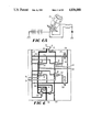
  • the operator When the cutter blade assembly has been opened sufficiently the operator returns the handle 18 to neutral position as in FIG. 1, manipulates the tractor or other equipment to place a tree in the grasp of the cutter blade assembly, and then manipulates the handle to the position of FIG. 3.
  • the hydraulic condition of FIG. 3 will prevail until the cutter blade assembly closes upon the tree and sufficient pressure builds up due to resistance to movement of the piston 28, to automatically open the pressure responsive valve 46.
  • the second fluid inlet port 38 is connected with drain, whereas the first fluid inlet port 36 is connected with pressurized fluid directly to pressurize the base end of the piston/cylinder assembly 24 and expel fluid from the rod end of the assembly.

Abstract

An hydraulic system for operating double acting piston/cylinder assemblies and for effecting automatic transition from a regenerative mode of operation of a double acting piston/cylinder assembly to a non-regenerative mode of operation thereof. Pressure responsive valve means automatically converts the hydraulic system from one initially being a high-speed/low force operation to a high force/low speed operation.

Description

BACKGROUND OF THE INVENTION
1. Field of the Invention
The invention relates to hydraulic systems for supplying and controlling pressurized fluid and drain to one or more double acting piston-cylinder assemblies. The invention also relates to means for automatically transposing from a regenerative to a non-regenerative flow with respect to a double acting piston-cylinder assembly.
2. Prior Art
Insofar as the prior art relates to flow control systems which serve a plurality of double acting piston-cylinder assemblies under manual control of an operator by means of a control valve lever and switches which may be mounted on the operator's stalk, the closest prior art known is the Balzer U.S. Pat. No. 3,512,453, noting particularly column 2 at lines 61-64. Other patents of interest are U.S. Pat. Nos. 4,244,405; 3,854,380; 3,705,631; and 3,589,242.
Insofar as the prior art relates to systems which automatically transpose from regenerative to non-regenerative flow, the closest prior art known is the Haarmeyer U.S. Pat. No. 2,800,110. Other patents of interest are the Ikeda U.S. Pat. No. 3,759,144; the Friesen et al. U.S. Pat. No. 4,397,221; the Brundidge et al. U.S. Pat. No. 4,216,702; the Christensen et al. U.S. Pat. No. 3,643,696; the Rice U.S. Pat. No. 3,335,739; and the Hall et al. U.S. Pat. No. 4,152,970.
BRIEF SUMMARY OF THE INVENTION
This invention relates to hydraulic systems for operating double acting piston/cylinder assemblies and is concerned in one embodiment with hydraulic circuitry for effecting automatic transition from a regenerative mode of operation of a double acting piston/cylinder assembly to a non-regenerative mode of operation thereof.
The non-regenerative mode is characterized by the fact that it is automatically effected by a hydraulic condition which abruptly connects the rod end of the piston/cylinder assembly to hydraulic drain pressure while the base end of the assembly remains directly connected to the hydraulic pressure fluid supply. In this way, substantially full hydraulic power is applied in the non-regenerative mode of operation, without back pressure at the rod end of the assembly.
The hydraulic circuitry by which the automatic transition is made possible is characterized by its simplicity of construction and includes the provision of full hydraulic pressure supply to the base end of the piston/cylinder assembly prior to, during and subsequent to the transition.
In another embodiment, this invention is concerned with hydraulic circuitry in which manual control means is provided to control a central control unit so that the operator may select to supply and control one of a plurality of hydraulic circuits from a common hydraulic supply source, each of the circuits including a double acting piston/cylinder assembly. In this aspect, the aforesaid automatic transition from regenerative mode to non-regenerative mode may be incorporated within the central control unit of the invention to operate in a single one or any combination of the selected circuits.
The control for selection of the desired piston/cylinder assembly to be operated is characterized by its simplicity of construction, including the provision of a pilot fluid pressure line and a pilot fluid drain line and solenoid operated valve means for connecting the pilot fluid pressure line with the pilot fluid drain line so as to operate at least one directional control valve which effects the selection of the piston/cylinder assembly to be actuated.
In one aspect, then, the invention relates to an improved circuitry for automatically effecting transition from regenerative mode to non-regenerative mode in a simple and efficient manner. With regard to this, between the operator-controlled valve and the piston/cylinder assembly, first path means is provided which directly connects one outlet of the controlled valve to the base end of the piston/cylinder assembly in those positions of the valve in which such one outlet respectively provides pressurized fluid to the base end and connects it to drain. Second flow path means connects the other or second outlet of the controlled valve to the rod end of the piston/cylinder assembly for normally blocking fluid flow from the rod end of the assembly when the second outlet is connected to drain and for allowing flow from the second outlet to the rod end of the assembly when the second outlet is connected to pressure fluid. A third flow path means is provided to connect the rod end to the base end for allowing pressurized fluid flow from the rod end to the base end to effect the regenerative mode of operation. The second flow path means includes pressure responsive valve means for dumping the rod end to drain in response to attainment of a set pressure at the rod end of the assembly, therby effecting the automatic transition from regenerative to non-regenerative mode of operation.
BRIEF DESCRIPTION OF THE DRAWING FIGURES
FIG. 1 is a diagrammatic view illustrating one embodiment of the invention;
FIG. 2 is a diagrammatic view of the embodiment of FIG. 1 illustrating the piston retracting mode of operation;
FIG. 3 is a diagrammatic view of the embodiment of FIG. 1 illustrating the regenerative piston extending mode of operation;
FIG. 4 ia a diagrammatic view of the embodiment of FIG. 1 illustrating the non-regenerative piston extending mode of operation;
FIG. 5 is a diagrammatic view illustrating another embodiment of the invention;
FIG. 6 is a diagrammatic view of the embodiment of FIG. 5 illustrating the piston retracting mode of operation for one of the piston/cylinder assemblies being served;
FIG. 6A illustrates the operator control position associated with FIG. 6;
FIG. 7 is a diagrammatic view illustrating the regenerative piston extending mode of operation related to FIG. 6;
FIG. 7A illustrates the operator control position associated with FIG. 7;
FIG. 8 is a diagrammatic view illustrating the non-regenerative piston extending mode of operation related to FIG. 6;
FIG. 8A illustrates the operator control position associated with FIG. 8;
FIG. 9 is a diagrammatic view corresponding to FIG. 6 but illustrating control of a second piston/cylinder assembly;
FIG. 9A illustrates the operator control position associated with FIG. 9;
FIG. 10 is a diagrammatic view corresponding to FIG. 8 but illustrating control of the second piston/cylinder assembly;
FIG. 10A illustrates the operator control position associated with FIG. 10;
FIG. 11 is a diagrammatic view corresponding with FIG. 9 but illustrating control of a third piston/cylinder assembly;
FIG. 11A illustrates the operator control position associated with FIG. 11;
FIG. 12 is a diagrammatic view corresponding with FIG. 10 but illustrating the control of the third piston/cylinder assembly; and
FIG. 12A illustrates the operator control position associated with FIG. 12.
DETAILED DESCRIPTION OF THE INVENTION
FIG. 1 illustrates one embodiment of the invention and the hydraulic system associated therewith. As shown, the hydraulic system includes the source or pump P having the inlet line 10 and the outlet line 12. The inlet line picks up hydraulic fluid from the reservoir 14 and the pump delivers the fluid under the requisite pressure to the operator-controlled valve 16. The usual pressure relief valve for the pump is not illustrated for clarity but it will be understood that all of the usual elements of the normal hydraulic system will be provided as will be understood by those of ordinary skill in the art. The operator-controlled valve may of any conventional form and is provided with a control handle 18 which may be moved from the neutral position shown to either of the noraml control positions. In one control position, the pressure line 12 is connected to the outlet 20 while the second outlet 22 is connected to drain, i.e., to the reservoir 14 via the drain line 13. In the other control position, the connections are reversed so that the outlet 22 is connected to the pressure line 12 and the outlet 20 is connected to the drain line 13.
The basic control unit of this embodiment of the invention serves the piston/cylinder assembly 24 which includes the cylinder 26 within which the piston 28 operates and from which projects the piston rod 30 for operating an associated device. The assembly is provided with a base end connection 32 and a rod end connection 34 in the usual configuration of a double acting assembly as will be understood by those of ordinary skill in the art.
The control unit is provided with a first fluid inlet port 36 and a second fluid inlet port 38. The control unit may be conditioned so that these two ports are disconnected from both fluid pressure and drain; the first inlet port is connected to pressurized fluid while the second inlet port is connected to drain; or the second inlet port is connected to pressurized fluid while the first inlet port is connected to drain, dependent upon the position of the control valve 16. At the outlet side of the control unit, the first fluid outlet port 40 is connected with the base end connection 32 of the double acting piston/cylinder assembly 24 whereas the second fluid outlet port 42 is connected with the rod end of the assembly. From FIG. 1, it will be evident that there is a direct fluid flow path means established between the first fluid inlet port 36 and the base end of the double acting piston/cylinder assembly 24 so that whenever the first fluid inlet port is connected to pressurized fluid, the base end of the assembly 24 will be pressurized to extend the piston 28 and its rod 30. Likewise, when the first inlet port 20 is connected to drain, the base end of the assembly 24 is directly connected to drain. The importance of this arrangement will become evident as this description proceeds.
The control unit includes second fluid flow path means between the inlet port 38 and the outlet port 42. When the inlet port 38 is connected with pressurized fluid, this second fluid flow path means is through the check valve 44 and allows the pressurized fluid to flow to the rod end of the assembly 24 while fluid being expelled from the base end of the piston/cylinder assembly 24 flows through the first fluid flow path means from the base end of the assembly 24 directly to drain. This condition is illustrated in FIG. 2. From this Figure, it will be seen that the fluid under pressure flows from the second inlet port 38, through the check valve 44 to the outlet port 42 to pressurize the rod end of the assembly 24 causing the fluid in the base end thereof to be expelled through the outlet port 40 to the inlet port 36 and drain. That branch of the second fluid flow path means containing the pressure responsive valve 46 will be blocked and the pressure in the pilot line 48 controls the pilot controlled check valve 50 to remain closed so that the third fluid flow path means containing this valve 50 is inoperative at this time. The condition of FIG. 2 is established by the operator upon manipulating the control valve handle 18 to the position illustrated in FIG. 2 and serves to retract the piston rod 30. The device operated by the assembly may be, for example, the cutting shears of a tree cutter and the condition of FIG. 2 would operate to open the cutter blade assembly preparatory to receiving the trunk of a tree for subsequent cutting action.
When the cutter blade assembly has been opened sufficiently the operator returns the handle 18 to neutral position as in FIG. 1, manipulates the tractor or other equipment to place a tree in the grasp of the cutter blade assembly, and then manipulates the handle to the position of FIG. 3. The hydraulic condition of FIG. 3 will prevail until the cutter blade assembly closes upon the tree and sufficient pressure builds up due to resistance to movement of the piston 28, to automatically open the pressure responsive valve 46. As shown, the second fluid inlet port 38 is connected with drain, whereas the first fluid inlet port 36 is connected with pressurized fluid directly to pressurize the base end of the piston/cylinder assembly 24 and expel fluid from the rod end of the assembly. The fluid being expelled from the rod end of the piston/cylinder assembly is blocked by that portion of the second fluid flow path means containing the check valve 44 and is also blocked by that portion of the second fluid flow path means containing the pressure responsive valve 46. However, since the pilot line 48 of the pilot controlled check valve 50 is at drain pressure at this time, the fluid being expelled is free to flow through the third fluid flow path means from the rod end into the base end of the piston/cylinder assembly 24 in the well known regenerative fashion. This operates to extend the rod 30 in high speed/low force fashion.
When the cutter blade assembly engages the tree the pressure at the rod end of the assembly begins to rise suddenly and this increased pressure is transmitted to the pressure responsive valve 46 at the pilot line 52 and functions, at a predetermined and set pressure, automatically to open this valve and dump the rod end pressure directly to drain. In this way, the regenerative mode of operation is automatically terminated and transposition to non-regenerative mode is effected with substantially no back pressure at the rod end of the piston/cylinder assembly 24. In order to assure this effect, the valve 46 must be of the type which allows substantially unrestricted flow when it has been opened. For this purpose, it is preferred that the valve 46 be a model SOHB "kick down sequence valve" available from Sun Hydraulics Corp. A valve of this type is adjustable as to setting at which the valve will effect the transition from closed to open mode, and it is preferred that such valve be set at about 1700 psi for systems of this invention which are employed with tractors having a maximum of about 3000 psi capability. With valves of this type, once the set pressure has been attained and the valve has kicked down to the open position, the valve will remain in the open condition until the pilot line 52 is subjected to positive pressure as occurs when the condition of FIG. 2 is reestablished. The pilot fluid drain line 53 for the valve 46 is connected to system drain as is shown in FIG. 1.
The non-regenerative mode of operation is illustrated in FIG. 4. As shown, the valve 46 is in open condition due to attainment of the set pressure in the pilot line 52 when operating in the regenerative mode of FIG. 3. The normal action of the check valve 50 prevents back flow of fluid from the base end to the rod end of the piston/cylinder assembly 24 or, as stated otherwise, the third fluid flow path means is effective only as a one way path from the rod end to the base end of the assembly 24. The non-regenerative mode of operation is a low speed/high force mode which, because of the substantial absence of back pressure at the rod end of the piston/cylinder assembly, allows substantially the full available hydraulic pressure to be utilized for useful work.
A modified hydraulic system and control unit of this invention is illustrated in FIGS. 5-12A. With reference to FIG. 5, the control valve 16 is employed as in the above described Figures, operating as described but in this instance selectively to service one of three different piston/cylinder assemblies. For this purpose, the control unit is provided with two inlet ports 60 and 62 and with three pairs of outlet ports 64, 66; 68, 70; and 72, 74. The selection of which pair of outlet ports is to be served is made by the operator, as will presently be apparent. The selection involves the several spool valves 76, 78, 80, and 82. In the normal positions of these valves, shown in FIG. 5, a fluid flow path means is established from the inlet port 60 to the outlet port 68 which is connected to the base end of the double acting piston/cylinder assembly as in FIGS. 1-4. Likewise, the second fluid flow path means between the inlet port 62 and the oulet port 70 is established through the check valve 44 and through the sequence valve 46 as was described above, and the third fluid flow path means also is provided between the two outlets 68 and 70 through the pilot controlled check valve 50.
When the operator's handle or stalk 18 is manipulated to the position of FIG. 6A, pressurized fluid is connected to the second fluid flow path means as is indicated in FIG. 6, thereby to pressurize the rod end of the double acting piston/cylinder assembly and operate it in the high speed, shear-opening mode as was described in conjunction with FIG. 2. When the shear assembly has been opened the desired amount, the stalk 18 is returned to the neutral position and the tractor or the like maneuvered to position the shear assembly in operative relation to the tree desired to be cut, whereupon the handle 18 is moved to the position shown in FIG. 7A. This pressurizes the inlet port 60 and connects the inlet port 62 to drain, exactly as was described in conjunction with FIG. 3 to operate the piston-cylinder assembly in the regenerative mode. Because of the presence of the sequence valve 46, the transition from the regenerative mode to the non-regenerative mode, shown in FIG. 8 is effected automatically when the set pressure of the valve 46 is reached at the rod end of the piston/cylinder assembly, the handle 18 having remaining in the same position as it was in FIG. 7A, see FIG. 8A.
When the hydraulic piston/cylinder assembly served by the outlet ports 64, 66 is chosen for operation, the operator simultaneously positions the handle 18 and operates the switch mechanism 84 as shown in FIG. 9A. The switch mechanism is provided with a voltage/current source 86 having the conductor 88 connected in common with the two switches 90 and 92. In the position of the switch lever 94 as in FIG. 10A, the switch 90 is closed so that its conductor 96 energizes the solenoid winding 98. The diode 100 is provided for protective purposes. the winding 98 is part of the solenoid 102 which controls the pilot fluid valve 104 to open it and thereby connect the pilot fluid pressure supply line 106 to the drain line 53 through the restrictor 108. The supply line 106 is externally connected to a suitable source of hydraulic fluid pressure. The flow restrictor 108 operates to assure that the drain line remains substantially at the drain pressure while the upstream section 110 of the pilot line between the restrictor and the valve 104 is at at the requisite pilot fluid pressure. The hydraulic actuators 112 and 114 cause the pilot operated valves 76 and 78 to move to the positions shown in FIG. 9 to connect the inlet port 60 to the outlet port 64 and the inlet port 62 to the outlet port 66. If, now, the assembly served by the outlet ports 64 and 66 is desired to be operated in the opposite direction, the handle 18 must be manipulated to the position shown in FIG. 10A while the switch lever is in the same position as described for FIG. 9A. The positions of the valves 76 and 78 will not change but the pressure/drain connections for the inlet ports 60 and 62 will be reversed as illustrated in FIG. 10.
FIGS. 11-12A illustrate the positions for the handle and the switch lever 94 which control the assembly served by the outlet ports 72 and 74. The only difference between these Figures and FIGS. 9-10A is that the switch lever 94 is now in the position to close the switch 92 so as to energize the solenoid winding 122 associated with the solenoid 124 for operating the valve 126. Under this condition, the valve 126 is opened to connect the pilot pressure line 106 to the drain line 53 through the restrictor 128 to operate the flow direction control valves 80 and 82 to the positions shown in FIGS. 11 and 12. Thus, the outlet port 72 is connected to the inlet port 60 and the outlet port 74 is connected to the inlet port 62, the pressure/drain connections to these inlet ports being controlled by the position of the handle 18 (FIGS. 11A and 12A).
While an embodiment of a directional control valve and a regeneration valve in a control circuit and modifications thereof have been shown and described in detail herein, various other changes and modifications may be made without departing from the scope of the present invention.

Claims (14)

What is claimed is:
1. A system having a plurality of double acting hydraulic piston/cylinder assemblies which are to be operated individually and at selected times, comprising the combination of:
an operator-controlled valve adapted to be connected both to a source of pressurized hydraulic fluid and to drain therefor, and having first and second outlets respectively connected to the source and drain in one position of the operator-controlled valve and vice versa in another position of the operator-controlled valve;
a control unit including first and second fluid inlet ports connected respectively to said first and second outlets to receive pressurized fluid at said first inlet port while said second fluid inlet port is connected to drain, and vice versa, dependent upon the position of said operator-controlled valve;
said control unit also including first and second fluid outlet ports adapted to supply the base end and the rod end of a first double acting piston/cylinder assembly respectively with pressurized fluid and drain connection, and vice versa, dependent upon the position of said operator-controlled valve;
said control unit further including third and fourth fluid outlet ports adapted to supply the base end and the rod end of a second double acting piston/cylinder assembly respectively with pressurized fluid and drain connection, and vice versa, dependent upon the position of said operator-controlled valve; and
said control unit including directional flow control valve means for selectively blocking flow from said first and second inlet ports either to said first and second outlet ports or to said third and fourth outlet ports, said flow control valve means comprising pilot fluid controlled valve means for normally allowing flow only from said first and second fluid inlet ports to said first and second outlet ports, a pilot fluid pressure line and a pilot fluid drain line, and solenoid operated valve means for allowing said pilot fluid pressure line to communicate with said pilot fluid drain line while actuating said pilot fluid controlled valve means to allow flow only from said first and second inlet ports to said third and fourth outlet ports.
2. A system as defined in claim 1 including fluid pressure responsive means connecting said second fluid outlet port to said first fluid outlet port for allowing fluid under pressure to flow from said second fluid outlet port to said first fluid outlet port to effect a regenerative fluid flow to and from the piston-cylinder assembly served by said first and second outlet ports; and
fluid responsive means for allowing said second fluid outlet port to be connected to drain at said second fluid inlet port in response to a predetermined pressure of fluid at said second fluid outlet port so as automatically to transpose to non-regenerative fluid flow to and from the piston/cylinder assembly served by said first and second outlet ports.
3. A control unit for hydraulic circuits adapted to receive the reversible pressure/drain hydraulic fluid outputs of a manual control valve and to supply at least one double-acting hydraulic piston/cylinder assembly, said control unit including first fluid flow path means for directly connecting the base end of a supplied piston/cylinder assembly alternatively to pressurized fluid and to drain dependent upon the controlled position of the manual control valve, second fluid flow path means for connecting the rod end of the supplied piston/cylinder assembly alternatively to pressurized fluid and to drain dependent upon the controlled position of the manual control valve, third flow path means for connecting the rod end to the base end of the supplied piston/cylinder assembly, and pressure responsive valve means in said second and said third flow path means for automatically transposing operation of the supplied piston/cylinder assembly from a regenerative, high speed, low force mode to a non-regenerative, high force, low speed mode when said first flow path means is supplied with pressurized fluid and said second flow path means is connected to drain, said pressure responsive valve means including a pressure sensitive valve in said second fluid flow path means, a pressure sensitive check valve in said third fluid flow path means, and a pilot line connecting the pressure sensitive check valve with said second fluid flow path means at a location between the pressure sensitive valve and the manual control valve.
4. In a hydraulic system for operating a piston/cylinder assembly in a compound extending mode of operation comprising an initial regenerative operation of the piston/cylinder assembly which automatically transposes to non-regenerative operation in response to attainment of predetermined resistance to operation of the piston/cylinder assembly, the combination of:
direct flow path means for extending and retracting the assembly;
regenerative fluid flow path means for allowing fluid to flow regeneratively under pressure between the ends of the piston/cylinder assembly; and
pressure responsive valve means for automatically draining one end of the piston/cylinder assembly when the predetermined resistance to operation of the assembly is encountered so as to transpose to the non-regenerative operation, said pressure responsive valve means including a pressure sensitive valve in said direct flow path means, a parallel fluid flow path within said direct flow path means around said pressure sensitive valve, a pressure sensitive check valve in said parallel fluid flow path, and a pilot line connecting said parallel fluid flow path to said pressure sensitive valve, the check valve and the pilot line serving to regulate the pressure to said pressure sensitive valve.
5. In a hydraulic system for operating a piston/cylinder assembly in a compound mode of operation comprising an initial regenerative operation of the piston/cylinder assembly which automatically transposes to non-regenerative operation in response to attainment of predetermined resistance to operation of the piston/cylinder assembly, the combination of:
an operator-controlled valve adapted to be connected both to a source of pressurized hydraulic fluid and to drain therefor, and having first and second outlets respectively connected to the source and drain in one position of the operator-controlled valve;
first fluid flow path means for directly connecting said first outlet to the base end of the piston/cylinder assembly in any position of said operator-controlled valve;
second fluid flow path means for normally blocking flow of fluid from the rod end of the piston/cylinder assembly;
third fluid flow path means connecting said rod end to said base end of the piston/cylinder assembly for allowing fluid to flow regeneratively under pressure from said rod end to said base end of the piston/cylinder assembly including a first check valve and a first pilot line connecting said first check valve to said second fluid flow path, said first check valve and said first pilot line rendering the third fluid flow path inoperative when the pressure in said first pilot line exceeds a selected value; and
said second fluid flow path means including pressure responsive valve means, a second check valve and a second pilot line, said second check valve and said second pilot line regulating the pressure to said pressure responsive valve means, for connecting said rod end of the piston/cylinder assembly to drain in response to attainment of a set pressure at said rod end of the piston/cylinder assembly whereby automatically to effect the transition from the regenerative operation to the non-regenerative operation.
6. A hydraulic system for operating a double-acting piston/cylinder assembly in a single mode in that direction of operation in which the piston is being retracted and in a compound mode in the opposite direction of operation in which the piston is being extended, the compound mode being an initial regenerative operation of the piston/cylinder assembly which automatically transposes to non-regenerative operation in response to attainment of predetermined resistance to operation of the piston/cylinder assembly while the piston is being extended, comprising the combination of:
an operator-controlled valve adapted to be connected both to a source of pressurized hydraulic fluid and to drain therefor, and having first and second outlets respectively connected to the source and drain in one position of the operator-controlled valve and vice versa in another position of the operator-controlled valve;
first fluid flow path means connecting said first outlet directly to the base end of said double-acting piston/cylinder assembly for subjecting said base end of the piston/cylinder assembly to fluid pressure when the operator-controlled valve is in said one position and for connecting said base end of the piston/cylinder assembly to drain when the operator-controlled valve is in said another position;
second flow path means connecting said second outlet to the rod end of said double-acting piston/cylinder assembly for allowing pressurized fluid to flow from said second outlet to the rod end of the piston/cylinder assembly when said operator-controlled valve is in said another position and normally to block flow of fluid from the rod end of the piston/cylinder assembly to said second outlet when the operator-controlled valve is in said one position;
third flow path means connecting the rod and base ends of the piston/cylinder assembly for allowing fluid to flow regeneratively from the rod end to the base end when said operator-controlled valve is in said one position and for blocking flow between the rod end and the base end when said operator-controlled valve is in the another position;
said second flow path means including first pressure responsive valve means for connecting said rod end of the piston/cylinder assembly to said second outlet when said operator-controlled valve is in said one position and the pressure at said rod end of the piston/cylinder assembly has attained a set value whereby automatically to effect the transition from the regenerative operation to the non-regenerative operation, said first pressure responsive valve means including a pressure sensitive valve, a parallel flow path within said second flow path means around said pressure sensitive valve, a pressure sensitive check valve in said parallel flow path, and a pilot line connecting said parallel flow path to said pressure sensitive valve serving to regulate the pressure to said pressure sensitive valve.
7. A control unit as defined in claim 6 including third and fourth fluid outlet ports to serve a second piston/cylinder assembly and controllable valve means for connecting said first and second inlet ports to said third and fourth outlet ports.
8. A control unit as defined in claim 7 including fifth and sixth fluid outlet ports to serve a third piston/cylinder compound mode in the opposite direction of operation in which the piston is being extended, the compound mode being an initial regenerative operation of the piston/cylinder assembly which automatically transposes to non-regenerative operation in response to attainment of predetermined resistance to operation of the piston/cylinder assembly while the piston is being extended, comprising the combination of:
an operator-controlled valve adapted to be connected both to a source of pressurized hydraulic fluid and to drain therefor, and having first and second outlets respectively connected to the source and drain in one position of the operator-controlled valve and vice versa in another position of the operator-controlled valve;
first fluid flow path means connecting said first outlet directly to the base end of said double-acting piston/cylinder assembly for subjecting said base end of the piston/cylinder assembly to fluid pressure when the operator-controlled valve is in said one position and for connecting said base end of the piston/cylinder assembly to drain when the operator-controlled valve is in said another position;
second flow path means connecting said second outlet to the rod end of said double-acting piston/cylinder assembly for allowing pressurized fluid to flow from said second outlet to the rod end of the piston/cylinder assembly when said operator-controlled assembly and second controllable valve means for connecting said first and second inlet ports to said fifth and sixth outlet ports.
9. A control unit as defined in claim 3 including third and fourth fluid outlet ports to serve a second piston/cylidner assembly and controllable valve means for connecting said first and second inlet ports to said third and fourth outlet ports.
10. A control unit as defined in claim 9 including fifth and sixth fluid outlet ports to serve a third piston/cylinder assembly and second controllable valve means for connecting said first and second inlet ports to said fifth and sixth outlet ports.
11. A control unit as defined in claim 4 including third and fourth fluid outlet ports to serve a second piston/cylidner assembly and controllable valve means for connecting said first and second inlet ports to said third and fourth outlet ports.
12. A control unit as defined in claim 11 including fifth and sixth fluid outlet ports to serve a third piston/cylinder assembly and second controllable valve means for connecting said first and second inlet ports to said fifth and sixth outlet ports.
13. A control unit as defined in claim 5 including third and fourth fluid outlet ports to serve a second piston/cylidner assembly and controllable valve means for connecting said first and second inlet ports to said third and fourth outlet ports.
14. A control unit as defined in claim 13 including fifth and sixth fluid outlet ports to serve a third piston/cylinder assembly and second controllable valve means for connecting said first and second inlet ports to said fifth and sixth outlet ports.
US06/767,764 1985-08-21 1985-08-21 Directional control valve and regeneration valve Expired - Fee Related US4836088A (en)

Priority Applications (1)

Application Number Priority Date Filing Date Title
US06/767,764 US4836088A (en) 1985-08-21 1985-08-21 Directional control valve and regeneration valve

Applications Claiming Priority (1)

Application Number Priority Date Filing Date Title
US06/767,764 US4836088A (en) 1985-08-21 1985-08-21 Directional control valve and regeneration valve

Publications (1)

Publication Number Publication Date
US4836088A true US4836088A (en) 1989-06-06

Family

ID=25080517

Family Applications (1)

Application Number Title Priority Date Filing Date
US06/767,764 Expired - Fee Related US4836088A (en) 1985-08-21 1985-08-21 Directional control valve and regeneration valve

Country Status (1)

Country Link
US (1) US4836088A (en)

Cited By (12)

* Cited by examiner, † Cited by third party
Publication number Priority date Publication date Assignee Title
US4913616A (en) * 1989-02-23 1990-04-03 J. I. Case Company Hydraulic implement regeneration system
BE1006417A3 (en) * 1992-05-15 1994-08-23 Caterpillar Inc Fluid system recovery.
US5791226A (en) * 1996-05-25 1998-08-11 Samsung Heavy Industries Co., Ltd. Fluid regeneration device for construction vehicles
BE1010985A3 (en) * 1994-04-18 1999-03-02 Caterpillar Inc Hydraulic system including a valve mounting handset setting / locking and regeneration.
EP0867567A3 (en) * 1997-03-24 1999-03-10 Oyodo Komatsu Co., Ltd. Oil-pressure device
US5938183A (en) * 1998-08-04 1999-08-17 Hydraulic Power Systems, Inc. Braking assembly for use on a hydraulic winch
US20060096645A1 (en) * 2004-11-09 2006-05-11 Morten Halvorsen System for direct electrically operated hydraulic control valve
US20070144164A1 (en) * 2005-12-12 2007-06-28 Linde Aktiengesellschaft Control valve device for the control of a consumer
US20080141854A1 (en) * 2006-12-14 2008-06-19 Edwards Mfg. Co. Press having regeneration circuit
US7827787B2 (en) 2007-12-27 2010-11-09 Deere & Company Hydraulic system
US9162297B2 (en) 2009-11-30 2015-10-20 Caterpillar Work Tools B.V. Hydraulic device for hydraulic cylinders
US20220194559A1 (en) * 2020-12-22 2022-06-23 Goodrich Actuation Systems Sas Actuator overpressurising assembly

Citations (11)

* Cited by examiner, † Cited by third party
Publication number Priority date Publication date Assignee Title
US3227050A (en) * 1962-03-15 1966-01-04 Caterpillar Tractor Co Hydraulic circuit for actuation of an earthmoving scraper ejector
US3512453A (en) * 1968-05-22 1970-05-19 Caterpillar Tractor Co System for actuation of hydraulic motors on tractor powered implements
US3759144A (en) * 1970-08-17 1973-09-18 Amada Co Ltd Hydraulic actuating system for hydraulically operated bending machine
US3851566A (en) * 1973-01-13 1974-12-03 Bosch Gmbh Robert Apparatus for controlling a hydraulic-lift tail gate arrangement of a cargo-carrying vehicle
US3854380A (en) * 1972-06-23 1974-12-17 Caterpillar Tractor Co Three-way lever control for hydraulic control circuit
US3935792A (en) * 1973-02-26 1976-02-03 Caterpillar Tractor Co. Pilot pump bleed control for earthmoving scrapers
US4128380A (en) * 1975-10-02 1978-12-05 Dr. Boy Kg Fluid pressure actuated drive for the closing unit of an injection moulding machine
US4216702A (en) * 1978-05-01 1980-08-12 Eaton Yale Ltd. Pressure sensing regenerative hydraulic system
US4421135A (en) * 1979-02-12 1983-12-20 Walter Kidde & Company, Inc. Hydraulic selector valve having joy stick control
US4638720A (en) * 1980-12-01 1987-01-27 Deere & Company Electro-hydraulic control system
US4702148A (en) * 1985-08-28 1987-10-27 Gewerkschaft Eisenhutte Westfalia Gmbh Control of the actuation of hydraulic consumers

Patent Citations (11)

* Cited by examiner, † Cited by third party
Publication number Priority date Publication date Assignee Title
US3227050A (en) * 1962-03-15 1966-01-04 Caterpillar Tractor Co Hydraulic circuit for actuation of an earthmoving scraper ejector
US3512453A (en) * 1968-05-22 1970-05-19 Caterpillar Tractor Co System for actuation of hydraulic motors on tractor powered implements
US3759144A (en) * 1970-08-17 1973-09-18 Amada Co Ltd Hydraulic actuating system for hydraulically operated bending machine
US3854380A (en) * 1972-06-23 1974-12-17 Caterpillar Tractor Co Three-way lever control for hydraulic control circuit
US3851566A (en) * 1973-01-13 1974-12-03 Bosch Gmbh Robert Apparatus for controlling a hydraulic-lift tail gate arrangement of a cargo-carrying vehicle
US3935792A (en) * 1973-02-26 1976-02-03 Caterpillar Tractor Co. Pilot pump bleed control for earthmoving scrapers
US4128380A (en) * 1975-10-02 1978-12-05 Dr. Boy Kg Fluid pressure actuated drive for the closing unit of an injection moulding machine
US4216702A (en) * 1978-05-01 1980-08-12 Eaton Yale Ltd. Pressure sensing regenerative hydraulic system
US4421135A (en) * 1979-02-12 1983-12-20 Walter Kidde & Company, Inc. Hydraulic selector valve having joy stick control
US4638720A (en) * 1980-12-01 1987-01-27 Deere & Company Electro-hydraulic control system
US4702148A (en) * 1985-08-28 1987-10-27 Gewerkschaft Eisenhutte Westfalia Gmbh Control of the actuation of hydraulic consumers

Cited By (15)

* Cited by examiner, † Cited by third party
Publication number Priority date Publication date Assignee Title
US4913616A (en) * 1989-02-23 1990-04-03 J. I. Case Company Hydraulic implement regeneration system
BE1006417A3 (en) * 1992-05-15 1994-08-23 Caterpillar Inc Fluid system recovery.
BE1010985A3 (en) * 1994-04-18 1999-03-02 Caterpillar Inc Hydraulic system including a valve mounting handset setting / locking and regeneration.
US5791226A (en) * 1996-05-25 1998-08-11 Samsung Heavy Industries Co., Ltd. Fluid regeneration device for construction vehicles
US5996465A (en) * 1997-03-24 1999-12-07 Oyodo Komatsu Co., Ltd. Oil pressure device
EP0867567A3 (en) * 1997-03-24 1999-03-10 Oyodo Komatsu Co., Ltd. Oil-pressure device
US5938183A (en) * 1998-08-04 1999-08-17 Hydraulic Power Systems, Inc. Braking assembly for use on a hydraulic winch
US20060096645A1 (en) * 2004-11-09 2006-05-11 Morten Halvorsen System for direct electrically operated hydraulic control valve
US20070144164A1 (en) * 2005-12-12 2007-06-28 Linde Aktiengesellschaft Control valve device for the control of a consumer
US7540231B2 (en) * 2005-12-12 2009-06-02 Linde Material Handling Gmbh Control valve device for the control of a consumer
US20080141854A1 (en) * 2006-12-14 2008-06-19 Edwards Mfg. Co. Press having regeneration circuit
US7827787B2 (en) 2007-12-27 2010-11-09 Deere & Company Hydraulic system
US9162297B2 (en) 2009-11-30 2015-10-20 Caterpillar Work Tools B.V. Hydraulic device for hydraulic cylinders
US20220194559A1 (en) * 2020-12-22 2022-06-23 Goodrich Actuation Systems Sas Actuator overpressurising assembly
US11821443B2 (en) * 2020-12-22 2023-11-21 Goodrich Actuation Systems Sas Actuator overpressurising assembly

Similar Documents

Publication Publication Date Title
US4836088A (en) Directional control valve and regeneration valve
US4250794A (en) High pressure hydraulic system
US4030623A (en) Hydraulic circuitry for an excavator
US4078681A (en) Dual pump hydraulic control system with predetermined flow crossover provision
US4337959A (en) Self-leveling and height control hydraulic system
JPH02266103A (en) Working circuit for single action hydraulic cylinder
CA2120052C (en) Hydraulic system for open or closed-centered systems
US4408518A (en) Series self-leveling valve
US5315828A (en) Valve assembly for load independent control of multiple hydraulic loads
US5865028A (en) Energy recovery device
US4089166A (en) Automatic pump control system
US4126083A (en) Attitude control for implement
US4610193A (en) Load control system
US5355773A (en) Hydraulic system for controlling contact pressure
CA1061680A (en) Hydraulic circuit for tree harvesting implement
JPH03189407A (en) Automatic pressure release device for hydraulic motor
PL117538B1 (en) Drill jig
US4505339A (en) Hydraulic control for a dozer blade
US4077445A (en) Hydraulic circuit for tree harvester
US4145957A (en) Pilot-operated valve structure
US3997007A (en) Implement positioning hydraulic control system
US4243271A (en) Hydraulic braking system
US4723478A (en) Series self-leveling valve
US4632158A (en) Power limiting hydraulic system
DE3709704A1 (en) HYDRAULICALLY ACTUATED STEERING DEVICE

Legal Events

Date Code Title Description
AS Assignment

Owner name: ROME INDUSTRIES, INC., P. O. BOX 48, CEDARTOWN, GE

Free format text: ASSIGNMENT OF ASSIGNORS INTEREST.;ASSIGNOR:SEABAUGH, DAVID T.;REEL/FRAME:004479/0103

Effective date: 19850821

AS Assignment

Owner name: ROME INDUSTRIES, INC., 600 FIRST SOURCE BANK CENTE

Free format text: ASSIGNMENT OF ASSIGNORS INTEREST.;ASSIGNOR:ROME INDUSTRIES, INC.;REEL/FRAME:004920/0344

Effective date: 19880330

AS Assignment

Owner name: ROME INDUSTRIES, INC., A IN CORP., GEORGIA

Free format text: TO CORRECT NAME OF ASSIGNOR IN ASSIGNMENT RECORDED JULY 25, 1988, REEL 4923 FRAME 1039;ASSIGNOR:ROME INDUSTRIES, INC., A GA CORP.;REEL/FRAME:005012/0181

Effective date: 19890103

FPAY Fee payment

Year of fee payment: 4

REMI Maintenance fee reminder mailed
LAPS Lapse for failure to pay maintenance fees
FP Lapsed due to failure to pay maintenance fee

Effective date: 19970611

STCH Information on status: patent discontinuation

Free format text: PATENT EXPIRED DUE TO NONPAYMENT OF MAINTENANCE FEES UNDER 37 CFR 1.362