US4845771A - Exposure monitoring in radiation imaging - Google Patents
Exposure monitoring in radiation imaging Download PDFInfo
- Publication number
- US4845771A US4845771A US07/067,923 US6792387A US4845771A US 4845771 A US4845771 A US 4845771A US 6792387 A US6792387 A US 6792387A US 4845771 A US4845771 A US 4845771A
- Authority
- US
- United States
- Prior art keywords
- radiation
- exposure
- penetrative
- signal
- imaging
- Prior art date
- Legal status (The legal status is an assumption and is not a legal conclusion. Google has not performed a legal analysis and makes no representation as to the accuracy of the status listed.)
- Expired - Lifetime
Links
Images


Classifications
-
- H—ELECTRICITY
- H05—ELECTRIC TECHNIQUES NOT OTHERWISE PROVIDED FOR
- H05G—X-RAY TECHNIQUE
- H05G1/00—X-ray apparatus involving X-ray tubes; Circuits therefor
- H05G1/08—Electrical details
- H05G1/26—Measuring, controlling or protecting
- H05G1/30—Controlling
-
- H—ELECTRICITY
- H05—ELECTRIC TECHNIQUES NOT OTHERWISE PROVIDED FOR
- H05G—X-RAY TECHNIQUE
- H05G1/00—X-ray apparatus involving X-ray tubes; Circuits therefor
- H05G1/08—Electrical details
- H05G1/26—Measuring, controlling or protecting
- H05G1/30—Controlling
- H05G1/36—Temperature of anode; Brightness of image power
-
- H—ELECTRICITY
- H05—ELECTRIC TECHNIQUES NOT OTHERWISE PROVIDED FOR
- H05G—X-RAY TECHNIQUE
- H05G1/00—X-ray apparatus involving X-ray tubes; Circuits therefor
- H05G1/08—Electrical details
- H05G1/26—Measuring, controlling or protecting
- H05G1/30—Controlling
- H05G1/38—Exposure time
- H05G1/42—Exposure time using arrangements for switching when a predetermined dose of radiation has been applied, e.g. in which the switching instant is determined by measuring the electrical energy supplied to the tube
- H05G1/44—Exposure time using arrangements for switching when a predetermined dose of radiation has been applied, e.g. in which the switching instant is determined by measuring the electrical energy supplied to the tube in which the switching instant is determined by measuring the amount of radiation directly
Definitions
- This invention relates generally to the field of imaging by use of penetrative radiation, and more particularly to apparatus and method for monitoring progress of an x-ray exposure and for aborting the exposure upon the occurrence of a predetermined amount of deviation from a predetermined standard of radiation accumulation of the cumulative monitored x-ray exposure.
- Radiographic imaging employs a source of penetrative radiation, such as an x-ray tube, and a means responsive to x-rays to indicate characteristics of a pattern of x-rays emergent from a subject when placed in the x-ray beam path between the source and the x-ray sensitive means.
- the x-ray sensitive means can take many forms, such as an x-ray screen, for converting x-rays to light, overlying a piece of light and x-ray sensitive film for producing a shadow graphic picture of the internal structure or condition of the subject.
- radiographic detectors have been embodied by cellularized detectors of various types, defining an area expanse and including many individual detectors each responsive to radiation incident upon its particular zone. See for example, U.S. Pat. No. 4,626,688, issued on Dec. 2, 1986 to Barnes, which is hereby expressly incorporated by reference.
- Some radiation imaging systems employ automatic exposure control.
- a feedback signal is produced which is a function of the level of x-ray exposure taking place over time.
- An x-ray sensor sometimes called a "paddle" is mounted in the vicinity of the x-ray sensitive means such as near or on a cassette holding a screen/film assembly.
- the sensor sometimes has comprised a photomultiplier tube which produces a voltage which is a function of the instantaneous level of x-ray energy incident upon the receiving face of the tube.
- Integrating circuitry is provided and coupled to the photomultiplier tube, which, in response to the tube's reaction to x-rays, produces a voltage signal which is a function of the time integral of x-ray energy which has been incident on the tube during the exposure.
- This integrated signal forms a ramp signal which is used to control the exposure by comparing it to a fixed threshold reference value.
- the exposure is allowed to run until the value of the ramp signal exceeds the reference value, or until a maximum predetermined interval of time has elapsed, whichever comes first.
- This predetermined time is commonly referred to as a "backup time”.
- the backup time value is often set to a time of several seconds or more, a time of five (5) or six (6) seconds being common.
- the ramp signal/backup time exposure control technique suffers from the disadvantage that, if radiation reaching the sensor or paddle is insufficient to increase the integrated radiation indicating ramp signal to the predetermined exposure termination threshold level prior to expiration of the backup time, the exposure will continue until the backup time runs out, without regard to the fact that, if the ramp signal is not increasing with sufficient speed, a poor exposure is likely being made. Thus, the patient is subjected to a dose of radiation for the entire backup time, only to learn later that the exposure was inadequate and would have to be performed again after corrective measures.
- At least two conditions can contribute to the failure of sufficient increase in the integrated radiation accumulation ramp signal.
- that ramp signal will not increase with sufficient speed if the screen/film cassette is not properly aligned in the x-ray beam from the source, since the radiation sensing paddle is usually mounted on or quite near the cassette itself.
- the source is moved to a position over the patient's chest, and the cassette moved to a location under his abdomen, actuation of the source will cause the propagation of x-rays through the patient's chest for the full backup period of several seconds without yielding any picture at all. The dose will thus have been wasted, and the patient would have to be re-exposed to the radiation this time with the cassette properly aligned.
- An object of this invention is to provide exposure control for radiographic imaging which monitors the cumulative progress of an ongoing exposure and aborts the exposure automatically in the event that the exposure appears from its early progress to be a likely failure.
- a radiation imaging system including a radiation source and a radiation responsive imaging means spaced from the source and aligned with radiation propogated from the source when actuated, such that the radiation responsive imaging means produces a representation of a pattern of radiation emergent from a subject located at an examination station between the source and the radiation responsive imaging means.
- the system also includes a radiation sensor located proximate the imaging means which is coupled to means for producing an electrical signal representing the integral of radiation detected by the sensor during an exposure. This integral representing signal substantially defines a ramp.
- the system of this invention monitors the progress of radiation accumulation during the exposure by periodically checking to determine whether the ramp signal is increasing at a predetermined rate with respect to time. This condition is referred to as a "ramp moving" condition.
- the system further includes means for aborting or terminating the exposure in response to the failure of the monitoring means to detect the ramp moving condition. Such termination results in the reduction of administration of radiation to the patient or subject where the monitoring indicates that the exposure is likely to be poor, and indicates the need for readjusting the system and restarting the exposure.
- the monitoring is carried out in real time, during the actual exposure, affording the possibility that, if the exposure appears, early on, likely to be poor, it can be terminated early in the cycle, saving the subject from the administration of unnecessary radiation.
- the embodiment of the present invention provides for immediate termination upon fault detection, as opposed to the backup time concept, in which the patient can receive unnecessary radiation dose even though the ongoing exposure is likely to be poor or useless for providing diagnostic information.
- the purpose of the present invention is to detect an improper x-ray exposure while operating under automatic exposure control and terminating that exposure early in its cycle to prevent unnecessary radiation dose and procedural time loss.
- automatic exposure control the exposure has been allowed to go to completion or to expiration of backup time and any error in equipment setup by an operator, or any equipment malfunction, is not revealed until the exposed film is developed. This results in wasted radiation exposure to the patient and potential repeated re-takes of subsequent exposures until it is realized by the operator that there is indeed equipment or procedural malfunction.
- This invention is embodied by means for sampling the automatic exposure control (AEC) ramp signal and to compare it to a reference voltage pattern scaled down to a fraction of the normal AEC reference voltage and to develop an early warning hardware signal which is susceptible of use to terminate the exposure in the early phase of the exposure cycle if the ramp has failed to reach its predetermined desired level for that point in the exposure cycle.
- AEC automatic exposure control
- In actual practice means is provided for continual checking of the AEC ramp utilizing, in a specific embodiment, hardware or a microcomputer to sample and analyze the ramp signal.
- a timer is initiated every 330 milliseconds.
- the AEC ramp signal is passed through an analog to digital converter and sampled. If the ramp is sensed to be in a "not moving" condition, the exposure is terminated and the operator is warned, via an operator panel displayed error code, of the failure of the ramp signal to increase with the desired speed.
- the ramp "not moving" condition is indicated in response to the failure of the ramp signal to increase by at least 40 millivolts during the 330 millisecond measured time interval.
- This invention is, however, not limited to use in connection with automatic exposure control mode. Even where the radiation imaging system employed is of the timed exposure variety, not normally calling for a ramp signal, means for providing a ramp signal can be utilized and embodiments of the present invention can be employed to continually monitor the progress of the exposure through its entirety, and can be used to terminate the exposure at an easy point in its cycle if equipment malfunction or maladjustment appears to render the exposure of poor quality.
- FIG. 1 is an elevational view of a radiation imaging system incorporating the present invention
- FIG. 2 is a detail view of a portion of the system illustrated in FIG. 1;
- FIG. 3 is another detailed view, in elevation, of the system of FIG. 1;
- FIG. 3A is a detail view of the assembly of FIG. 2 with portions thereof broken away.
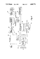
- FIG. 4 is a block diagram illustrating operation of aspects of the system of FIGS. 1-3;
- FIGS. 5-7 are graphical representations of operation of the system of the present invention.
- FIG. 8 and 8A are flow charts illustrating in more detail operation of a portion of the system as illustrated in FIG. 4;
- an x-ray apparatus is shown generally at 10.
- the apparatus includes an x-ray tube, not shown, mounted within a tube housing 11.
- the tube and the housing 11 are supported in an operative position by a suitable supporting structure 12.
- a subject supporting table 13 is disposed beneath the tube housing 11.
- the position of a subject to be examined is indicated in broken lines generally at 14.
- the x-ray tube emits x-rays in a beam emanating from a focal spot shown schematically at 15 and the x-rays are directed toward the subject 14 positioned on the table 13.
- a Bucky assembly 16 is positioned beneath the table 13.
- the Bucky assembly 16 is equipped with a usual reciprocable grid 17 and a cassette or film tray 18.
- An x-ray sensitive film 19 is positioned within the film tray 18 such that x-rays passing through the subject 14 will cast a shadow which is recorded by the film 19.
- a phototimer housing 20 is secured to the top and one side of the Bucky assembly 16. Referring to FIG. 2, the phototimer housing 20 defines first and second adjacent compartments 21, 22.
- the first compartment 21 houses a suitable light responsive electrical control element such as a phototube 23.
- the second compartment 22 houses a light emitting assembly 24 which, as will be explained in greater detail below, includes a fluorescent screen and a plurality of panels which transmit light to the phototube 23.
- a paddle structure 25 is positioned centrally with respect to the assembly 24 and comprises a plurality of juxtaposed panels.
- the paddle structure 25 along with a paddle mask 26 and an intensifier screen 27 are sandwiched between upper and lower cover plates 28, 29.
- the cover plate 28 is referred to as the upper cover plate in that it is positioned facing upwardly adjacent the Bucky tray 16.
- a frame assembly 30 receives and surrounds the sandwiched assembly 24.
- the photomultiplier tubes sense the incidence of x-rays on the cassette or film tray.
- Known circuitry coupled to the photomultiplier tube integrates the detected radiation and generates a ramp signal whose instantaneous value is a function of the accumulated radiation during the particular exposure.
- the system 10 is also equipped with circuitry of known type which terminates the exposure in response to the value of the ramp signal reaching a predetermined level which is preselected to represent the total radiation level desired for the exposure being made.
- the system 10 can incorporate a known form of backup timer which terminates the exposure in any event upon the expiration of a predetermined backup time which, in practice, is known generally as five or six seconds.
- the apparatus and circuitry for sensing the radiation, for integrating the radiation sensed, to produce the ramp signal, and for terminating the exposure when the ramp signal reaches a predetermined level is well known in the art, as is exemplified for example in U.S. Pat. No. 3,600,584 to Schneble, which is expressly incorporated by reference.
- Phototiming control circuitry is also described in detail in U.S. patent application Ser. No. 893,574, filed Aug. 4, 1986 by Griesmer, et al. and entitled "Improved Phototiming Control Method and Apparatus", which is also expressly incorporated herein by reference.
- FIG. 4 illustrates in block form components of the system described in connection with FIGS. 1-3. More specifically, the x-ray tube is shown at 50 in FIG. 4. The x-ray tube is actuated by x-ray driver circuits 52 of known design. The driver circuits 52 are actuated by exposure control circuitry 54, which enables the x-ray driver circuits 52 in response to various combinations of inputs, each input indicating a system condition or command control circuitry.
- a comparator 56 has two inputs. One of the inputs is the ramp signal, mentioned above, which appears at a lead 58. The other input is an analog signal representing the desired maximum reference value for the ramp signal, the reference signal appearing at a lead 60. In operation, when the ramp signal at the lead 58 becomes equal to the reference signal at the lead 60, the comparator 56 produces a stop signal at the lead 62 to the exposure control circuits which causes the exposure control circuitry to terminate the x-ray exposure.
- FIG. 4 illustrates an analog multiplexer circuit 66 which receives a number of analog inputs 68, including an analog input over a lead 70 corresponding to the ramp signal. An output from the analog multiplexer 66 is fed as an input to an analog to digital converter 72.
- the analog multiplexer 66 and analog to digital converter 72 are connected to one another, and to other components of the system, by a data and control bus of known design and indicated at reference character 74. More specifically, the data bus 74 couples together the following components: the analog multiplexer 66; the analog to digital converter 72 a digital to analog converter 76; a microcomputer 78; an input/output port 80, and an operator panel 82.
- the digital to analog converter 76 receives as an input a digital representation of the automatic exposure control reference threshold signal, which is the signal representing the maximum value to which the ramp is allowed to rise prior to exposure cut-off.
- the converter 76 converts this digital signal to the analog signal mentioned above appearing at the lead 60 as an input to the comparator 56.
- the value of the signal at the lead 60 is governed in known fashion by a selection made at the operator panel 82.
- the input/output port 80 has an output to the exposure control circuitry 54.
- the output at a lead 84, conditions the exposure control circuitry to terminate or to enable the generation of x-rays.
- exposure is enabled by the presence of a signal on an expose switch lead 88, which is actuated by an operator.
- the condition of the signal at the lead 84 of the input/output port 80 is determined by operation of the microcomputer 78.
- the microcomputer receives, over the bus 74, a digital signal corresponding to the substantially instantaneous value of the ramp signal appearing at the lead 70.
- the microcomputer 78 also contains timing and sampling means.
- the present invention involves sampling the ramp signal, such as appearing at the lead 70, and comparing it to a reference voltage which corresponds to the value of a ramp signal increment which would be expected during the most recent sampling time interval if all the equipment were properly aligned and functioning normally. This comparison is used to develop an "early warning indicator" signal to abort the exposure in its early phase if the actual sensed ramp signal at any point in its progress, failed to reach its expected limit.
- this invention involves continually checking on the automatic exposure control ramp signal using the microcomputer 78 to sample and analyze that ramp signal.
- a timer means which is part of the microcomputer, is initiated every 330 milliseconds.
- the automatic exposure control ramp signal is passed through the analog to digital converter and its digital expression of the ramp value is sampled.
- the analog to digital converter 72 is an 8 bit converter having a 10 volt scale such that a change of 40 millivolts in the ramp signal will result in a one bit change in the converter output.
- the ramp signal is sensed to be in a "not moving” or "insufficiently rapidly moving” condition, i.e., the ramp is not increasing as fast as would normally be expected in the instance of a proper exposure with a properly adjusted system, the exposure is aborted and the operator is warned via the operator panel 82 producing a code indicating a particular system malfunction involving the insufficient increase in the ramp signal.
- the microcomputer 78 also interfaces with an interrupt timer 90.
- FIG. 5 depicts a normal exposure sequence. Samples are taken after each time delay of 330 milliseconds. Each voltage sample is then compared to the previously sampled voltage for a minimum change of at least 40 millivolts, (i.e., one bit) which is considered a valid criterian of a ramp moving condition. The exposure progresses routinely until the ramp voltage exceeds the automatic exposure control reference, at which point the exposure is normally terminated by assertion of the stop signal by the comparator to the exposure control circuitry.
- V 1 , -V 0 , V 2 -V 1 , V 3 -V 2 , . . . V N -V N-1 are each greater than 40 millivolts, indicating a ramp moving condition
- V N+1 is reached, a ramp stop is indicated, and the exposure is terminated. Similar conditions pertain with respect to the ramp graph shown in FIG. 7, discussed below.
- the exposure was aborted after the first sample point, at which time it was determined by implementation of the present invention that there was substantially no change in the ramp voltage, i.e., less than 40 millivolts of change.
- the exposure would have continued until the back-up time had elapsed, which would have been several seconds longer, and the patient would have been needlessly exposed to radiation which was not going to yield a diagnostically useful x-ray image.
- FIG. 7 shows a normal exposure beginning to progress, followed by a fault condition in the ramp signal which was sensed by the implementation of this invention and the exposure was immediately aborted, eliminating the administration of unnecessary x-ray exposure to the patient.
- this invention is not limited to radiographic systems which operate in automatic exposure control mode, with the exception at an upper limit on the rate the ramp is moving may be set as well. Rather, this invention can be directed to radiographic systems operating under manual fixed time exposure control, to the extent that such systems are equipped with means for producing the ramp signal as described above. Operation of the invention is identical to that taking place in the automatic exposure control mode.
- the system will terminate an exposure after the first sample period in which it detects failure of the ramp to increase by a predetermined value, or if the ramp is increasing more rapidly than desired. If no faulty ramp condition is sensed, then the exposure will terminate at the regular fixed time selected for the exposure.
- the present invention may act as an exposure override, i.e., if the exposure time is erroneously set too long, the invention will interrupt the exposure at a properly timed out value, less than the set value.
- Both the sample time interval and voltage change difference selected to sense and determine whether the ramp is rising with sufficient speed can be varied or tailored to system parameters for both automatic and fixed exposure time applications.
- FIGS. 1-4 and the operational graphs of FIGS. 5-7 are sufficient for the person of ordinary skill in this art, a flow chart of microcomputer operation is set forth in FIG. 8 for those not conversant with the art.
- FIGS. 8 and 8A are flow charts indicating the operation of the microcomputer 78 and interrupt timer 90, in conjunction with the other components of the radiographic system.
- the microcomputer when an automatic exposure is requested by the appearance of an appropriate signal at the lead 88, the microcomputer initializes values for appropriate counter, flag and ramp signals. The microcomputer also calculates the fixed threshold reference value and sets the exposure enable signal to "on". Referring to block 102, the threshold reference value, i.e., the maximum value which the ramp will be allowed to attain, is written to the digital to analog converter 76. This analog voltage is used as a reference value which is compared to the ramp signal in the comparator 56 to generate the automatic exposure control stop signal which provides normal termination of exposure upon the ramp reaching its predetermined allowed maximum. The exposure enable signal is then written to the exposure control circuitry by way of the input/output port 80 allowing the exposure to begin.
- the threshold reference value i.e., the maximum value which the ramp will be allowed to attain
- the interrupt timer 90 is initialized when the system is powered on, and preempts the exposure control timing function whenever 10 milliseconds have elapsed and, at that time, will compare the counter (within the microcomputer) value to zero. If the counter value equals zero, then further processing is stopped. If the counter value is not equal to zero, then the counter is decremented and compared again to zero. If the counter at that point has reached zero, then a flag signal is set equal to "yes". If the counter has not yet reached zero, then further processing is stopped until the ten millisecond interval elapses and the process repeated until the counter reaches zero.
- the value which selects the AEC ramp 70 is written to the analog multiplexer 66 and then to the analog to digital converter 72.
- the bus 74 is read (block 106) for the digital representation actual ramp value.
- This representation is compared to the old, last sampled representation, and if the two values are not equal, (differ by one bit) which means the exposure is working correctly, then the timer is re-initialized (block 107) to time for another 330 millisecond delay.
- the formerly sampled ramp digital representation is reset to the most recently sampled digital representation.
- an error condition has been sensed, and the exposure is terminated.
- This (block 109) is accomplished by setting the exposure enable signal to off, and writing it to the exposure control circuits 54.
- an error information signal on an error display for the operator panel 82 will be lighted.
- the block 110 shows the re-setup of the equipment for a new exposure.
Abstract
Description
Claims (16)
Priority Applications (1)
| Application Number | Priority Date | Filing Date | Title |
|---|---|---|---|
| US07/067,923 US4845771A (en) | 1987-06-29 | 1987-06-29 | Exposure monitoring in radiation imaging |
Applications Claiming Priority (1)
| Application Number | Priority Date | Filing Date | Title |
|---|---|---|---|
| US07/067,923 US4845771A (en) | 1987-06-29 | 1987-06-29 | Exposure monitoring in radiation imaging |
Publications (1)
| Publication Number | Publication Date |
|---|---|
| US4845771A true US4845771A (en) | 1989-07-04 |
Family
ID=22079306
Family Applications (1)
| Application Number | Title | Priority Date | Filing Date |
|---|---|---|---|
| US07/067,923 Expired - Lifetime US4845771A (en) | 1987-06-29 | 1987-06-29 | Exposure monitoring in radiation imaging |
Country Status (1)
| Country | Link |
|---|---|
| US (1) | US4845771A (en) |
Cited By (71)
| Publication number | Priority date | Publication date | Assignee | Title |
|---|---|---|---|---|
| EP0809422A1 (en) * | 1996-05-20 | 1997-11-26 | General Electric Company | Method and system for detecting and correcting erroneous exposures generated during x-ray imaging |
| US5966425A (en) * | 1989-12-07 | 1999-10-12 | Electromed International | Apparatus and method for automatic X-ray control |
| US6327336B1 (en) | 2000-06-05 | 2001-12-04 | Direct Radiography Corp. | Radiogram showing location of automatic exposure control sensor |
| US6470207B1 (en) * | 1999-03-23 | 2002-10-22 | Surgical Navigation Technologies, Inc. | Navigational guidance via computer-assisted fluoroscopic imaging |
| US20030163038A1 (en) * | 2002-02-28 | 2003-08-28 | Simon David A. | Method and apparatus for perspective inversion |
| US20040227093A1 (en) * | 2003-05-14 | 2004-11-18 | International Business Machines Corporation | Radiation detecting system |
| US6892090B2 (en) | 2002-08-19 | 2005-05-10 | Surgical Navigation Technologies, Inc. | Method and apparatus for virtual endoscopy |
| US6920347B2 (en) | 2000-04-07 | 2005-07-19 | Surgical Navigation Technologies, Inc. | Trajectory storage apparatus and method for surgical navigation systems |
| US6968224B2 (en) | 1999-10-28 | 2005-11-22 | Surgical Navigation Technologies, Inc. | Method of detecting organ matter shift in a patient |
| US7007699B2 (en) | 1999-10-28 | 2006-03-07 | Surgical Navigation Technologies, Inc. | Surgical sensor |
| USRE39133E1 (en) | 1997-09-24 | 2006-06-13 | Surgical Navigation Technologies, Inc. | Percutaneous registration apparatus and method for use in computer-assisted surgical navigation |
| US7085400B1 (en) | 2000-06-14 | 2006-08-01 | Surgical Navigation Technologies, Inc. | System and method for image based sensor calibration |
| US7130676B2 (en) | 1998-08-20 | 2006-10-31 | Sofamor Danek Holdings, Inc. | Fluoroscopic image guided orthopaedic surgery system with intraoperative registration |
| US7174202B2 (en) | 1992-08-14 | 2007-02-06 | British Telecommunications | Medical navigation apparatus |
| US20080159481A1 (en) * | 2006-12-28 | 2008-07-03 | Canon Kabushiki Kaisha | Radiation imaging apparatus, method of controlling the radiation imaging apparatus and computer-readable storage medium |
| USRE40852E1 (en) | 1995-06-14 | 2009-07-14 | Medtronic Navigation, Inc. | Method and system for navigating a catheter probe |
| US7657300B2 (en) | 1999-10-28 | 2010-02-02 | Medtronic Navigation, Inc. | Registration of human anatomy integrated for electromagnetic localization |
| US7660623B2 (en) | 2003-01-30 | 2010-02-09 | Medtronic Navigation, Inc. | Six degree of freedom alignment display for medical procedures |
| US7697972B2 (en) | 2002-11-19 | 2010-04-13 | Medtronic Navigation, Inc. | Navigation system for cardiac therapies |
| US7751865B2 (en) | 2003-10-17 | 2010-07-06 | Medtronic Navigation, Inc. | Method and apparatus for surgical navigation |
| US7763035B2 (en) | 1997-12-12 | 2010-07-27 | Medtronic Navigation, Inc. | Image guided spinal surgery guide, system and method for use thereof |
| US7797032B2 (en) | 1999-10-28 | 2010-09-14 | Medtronic Navigation, Inc. | Method and system for navigating a catheter probe in the presence of field-influencing objects |
| US7835784B2 (en) | 2005-09-21 | 2010-11-16 | Medtronic Navigation, Inc. | Method and apparatus for positioning a reference frame |
| US7835778B2 (en) | 2003-10-16 | 2010-11-16 | Medtronic Navigation, Inc. | Method and apparatus for surgical navigation of a multiple piece construct for implantation |
| US7840253B2 (en) | 2003-10-17 | 2010-11-23 | Medtronic Navigation, Inc. | Method and apparatus for surgical navigation |
| US7881770B2 (en) | 2000-03-01 | 2011-02-01 | Medtronic Navigation, Inc. | Multiple cannula image guided tool for image guided procedures |
| US7925328B2 (en) | 2003-08-28 | 2011-04-12 | Medtronic Navigation, Inc. | Method and apparatus for performing stereotactic surgery |
| US7953471B2 (en) | 2004-05-03 | 2011-05-31 | Medtronic Navigation, Inc. | Method and apparatus for implantation between two vertebral bodies |
| US7974677B2 (en) | 2003-01-30 | 2011-07-05 | Medtronic Navigation, Inc. | Method and apparatus for preplanning a surgical procedure |
| US7998062B2 (en) | 2004-03-29 | 2011-08-16 | Superdimension, Ltd. | Endoscope structures and techniques for navigating to a target in branched structure |
| US8060185B2 (en) | 2002-11-19 | 2011-11-15 | Medtronic Navigation, Inc. | Navigation system for cardiac therapies |
| US8074662B2 (en) | 1999-10-28 | 2011-12-13 | Medtronic Navigation, Inc. | Surgical communication and power system |
| US8112292B2 (en) | 2006-04-21 | 2012-02-07 | Medtronic Navigation, Inc. | Method and apparatus for optimizing a therapy |
| US8165658B2 (en) | 2008-09-26 | 2012-04-24 | Medtronic, Inc. | Method and apparatus for positioning a guide relative to a base |
| USRE43328E1 (en) | 1997-11-20 | 2012-04-24 | Medtronic Navigation, Inc | Image guided awl/tap/screwdriver |
| US8175681B2 (en) | 2008-12-16 | 2012-05-08 | Medtronic Navigation Inc. | Combination of electromagnetic and electropotential localization |
| US8239001B2 (en) | 2003-10-17 | 2012-08-07 | Medtronic Navigation, Inc. | Method and apparatus for surgical navigation |
| USRE43952E1 (en) | 1989-10-05 | 2013-01-29 | Medtronic Navigation, Inc. | Interactive system for local intervention inside a non-homogeneous structure |
| US8452068B2 (en) | 2008-06-06 | 2013-05-28 | Covidien Lp | Hybrid registration method |
| US8473032B2 (en) | 2008-06-03 | 2013-06-25 | Superdimension, Ltd. | Feature-based registration method |
| US8494614B2 (en) | 2009-08-31 | 2013-07-23 | Regents Of The University Of Minnesota | Combination localization system |
| US8494613B2 (en) | 2009-08-31 | 2013-07-23 | Medtronic, Inc. | Combination localization system |
| US20130223592A1 (en) * | 2012-02-24 | 2013-08-29 | Fujifilm Corporation | Radiographic system, drive control method for radiographic system, recording medium for drive control program and radiological image detection device |
| US8611984B2 (en) | 2009-04-08 | 2013-12-17 | Covidien Lp | Locatable catheter |
| US8644907B2 (en) | 1999-10-28 | 2014-02-04 | Medtronic Navigaton, Inc. | Method and apparatus for surgical navigation |
| US8660635B2 (en) | 2006-09-29 | 2014-02-25 | Medtronic, Inc. | Method and apparatus for optimizing a computer assisted surgical procedure |
| US8663088B2 (en) | 2003-09-15 | 2014-03-04 | Covidien Lp | System of accessories for use with bronchoscopes |
| US8764725B2 (en) | 2004-02-09 | 2014-07-01 | Covidien Lp | Directional anchoring mechanism, method and applications thereof |
| US8838199B2 (en) | 2002-04-04 | 2014-09-16 | Medtronic Navigation, Inc. | Method and apparatus for virtual digital subtraction angiography |
| US8845655B2 (en) | 1999-04-20 | 2014-09-30 | Medtronic Navigation, Inc. | Instrument guide system |
| US8905920B2 (en) | 2007-09-27 | 2014-12-09 | Covidien Lp | Bronchoscope adapter and method |
| US8932207B2 (en) | 2008-07-10 | 2015-01-13 | Covidien Lp | Integrated multi-functional endoscopic tool |
| US9055881B2 (en) | 2004-04-26 | 2015-06-16 | Super Dimension Ltd. | System and method for image-based alignment of an endoscope |
| US9168102B2 (en) | 2006-01-18 | 2015-10-27 | Medtronic Navigation, Inc. | Method and apparatus for providing a container to a sterile environment |
| US9575140B2 (en) | 2008-04-03 | 2017-02-21 | Covidien Lp | Magnetic interference detection system and method |
| US9675424B2 (en) | 2001-06-04 | 2017-06-13 | Surgical Navigation Technologies, Inc. | Method for calibrating a navigation system |
| US10418705B2 (en) | 2016-10-28 | 2019-09-17 | Covidien Lp | Electromagnetic navigation antenna assembly and electromagnetic navigation system including the same |
| US10426555B2 (en) | 2015-06-03 | 2019-10-01 | Covidien Lp | Medical instrument with sensor for use in a system and method for electromagnetic navigation |
| US10446931B2 (en) | 2016-10-28 | 2019-10-15 | Covidien Lp | Electromagnetic navigation antenna assembly and electromagnetic navigation system including the same |
| US10478254B2 (en) | 2016-05-16 | 2019-11-19 | Covidien Lp | System and method to access lung tissue |
| US10517505B2 (en) | 2016-10-28 | 2019-12-31 | Covidien Lp | Systems, methods, and computer-readable media for optimizing an electromagnetic navigation system |
| US10582834B2 (en) | 2010-06-15 | 2020-03-10 | Covidien Lp | Locatable expandable working channel and method |
| US10615500B2 (en) | 2016-10-28 | 2020-04-07 | Covidien Lp | System and method for designing electromagnetic navigation antenna assemblies |
| US10638952B2 (en) | 2016-10-28 | 2020-05-05 | Covidien Lp | Methods, systems, and computer-readable media for calibrating an electromagnetic navigation system |
| US10722311B2 (en) | 2016-10-28 | 2020-07-28 | Covidien Lp | System and method for identifying a location and/or an orientation of an electromagnetic sensor based on a map |
| US10751126B2 (en) | 2016-10-28 | 2020-08-25 | Covidien Lp | System and method for generating a map for electromagnetic navigation |
| US10792106B2 (en) | 2016-10-28 | 2020-10-06 | Covidien Lp | System for calibrating an electromagnetic navigation system |
| US10952593B2 (en) | 2014-06-10 | 2021-03-23 | Covidien Lp | Bronchoscope adapter |
| US11006914B2 (en) | 2015-10-28 | 2021-05-18 | Medtronic Navigation, Inc. | Apparatus and method for maintaining image quality while minimizing x-ray dosage of a patient |
| US11219489B2 (en) | 2017-10-31 | 2022-01-11 | Covidien Lp | Devices and systems for providing sensors in parallel with medical tools |
| US11331150B2 (en) | 1999-10-28 | 2022-05-17 | Medtronic Navigation, Inc. | Method and apparatus for surgical navigation |
Citations (16)
| Publication number | Priority date | Publication date | Assignee | Title |
|---|---|---|---|---|
| US26497A (en) * | 1859-12-20 | Hydrocarbon-vapor apparatus | ||
| US2486866A (en) * | 1946-05-15 | 1949-11-01 | Us Sec War | Dual phototube X-ray timer for selective exposure of chest films |
| US3444379A (en) * | 1966-05-31 | 1969-05-13 | Gustav Bergson | Elimination of dark current effects in photomultiplier tubes |
| US3600584A (en) * | 1969-05-28 | 1971-08-17 | Gen Electric | X-ray phototimer that is compensated for dark current |
| US3752991A (en) * | 1971-06-28 | 1973-08-14 | Picker Corp | Photo timer |
| US3906233A (en) * | 1973-10-12 | 1975-09-16 | Varian Associates | System and method for administering radiation |
| US4087686A (en) * | 1975-11-10 | 1978-05-02 | Siemens Aktiengesellschaft | X-ray diagnostic apparatus for X-ray film photographs with an automatic exposure timer |
| US4121104A (en) * | 1975-12-17 | 1978-10-17 | U.S. Philips Corporation | X-ray examining device with automatic timer and film container for an X-ray examining device |
| US4178508A (en) * | 1977-07-30 | 1979-12-11 | Kabushiki Kaisha Morita Seisakusho | Device for controlling amount of X-ray irradiation |
| US4230944A (en) * | 1979-02-09 | 1980-10-28 | Advanced Instrument Development, Inc. | X-ray system exposure control with ion chamber |
| US4250103A (en) * | 1978-12-27 | 1981-02-10 | The Boeing Company | Radiographic apparatus and method for monitoring film exposure time |
| US4309613A (en) * | 1978-12-21 | 1982-01-05 | Siemens Aktiengesellschaft | X-Ray diagnostic device for fluoroscopic examination and film exposure |
| US4309612A (en) * | 1978-10-25 | 1982-01-05 | Siemens Aktiengesellschaft | X-Ray diagnostic generator with an inverter supplying the high voltage transformer |
| US4313055A (en) * | 1978-06-09 | 1982-01-26 | U.S. Philips Corporation | Automatic exposure control device for an X-ray generator |
| US4454606A (en) * | 1983-05-23 | 1984-06-12 | General Electric Company | Reconfigurable x-ray AEC compensation |
| US4590603A (en) * | 1984-01-09 | 1986-05-20 | General Electric Company | Automatic X-ray entrance dose compensation |
-
1987
- 1987-06-29 US US07/067,923 patent/US4845771A/en not_active Expired - Lifetime
Patent Citations (16)
| Publication number | Priority date | Publication date | Assignee | Title |
|---|---|---|---|---|
| US26497A (en) * | 1859-12-20 | Hydrocarbon-vapor apparatus | ||
| US2486866A (en) * | 1946-05-15 | 1949-11-01 | Us Sec War | Dual phototube X-ray timer for selective exposure of chest films |
| US3444379A (en) * | 1966-05-31 | 1969-05-13 | Gustav Bergson | Elimination of dark current effects in photomultiplier tubes |
| US3600584A (en) * | 1969-05-28 | 1971-08-17 | Gen Electric | X-ray phototimer that is compensated for dark current |
| US3752991A (en) * | 1971-06-28 | 1973-08-14 | Picker Corp | Photo timer |
| US3906233A (en) * | 1973-10-12 | 1975-09-16 | Varian Associates | System and method for administering radiation |
| US4087686A (en) * | 1975-11-10 | 1978-05-02 | Siemens Aktiengesellschaft | X-ray diagnostic apparatus for X-ray film photographs with an automatic exposure timer |
| US4121104A (en) * | 1975-12-17 | 1978-10-17 | U.S. Philips Corporation | X-ray examining device with automatic timer and film container for an X-ray examining device |
| US4178508A (en) * | 1977-07-30 | 1979-12-11 | Kabushiki Kaisha Morita Seisakusho | Device for controlling amount of X-ray irradiation |
| US4313055A (en) * | 1978-06-09 | 1982-01-26 | U.S. Philips Corporation | Automatic exposure control device for an X-ray generator |
| US4309612A (en) * | 1978-10-25 | 1982-01-05 | Siemens Aktiengesellschaft | X-Ray diagnostic generator with an inverter supplying the high voltage transformer |
| US4309613A (en) * | 1978-12-21 | 1982-01-05 | Siemens Aktiengesellschaft | X-Ray diagnostic device for fluoroscopic examination and film exposure |
| US4250103A (en) * | 1978-12-27 | 1981-02-10 | The Boeing Company | Radiographic apparatus and method for monitoring film exposure time |
| US4230944A (en) * | 1979-02-09 | 1980-10-28 | Advanced Instrument Development, Inc. | X-ray system exposure control with ion chamber |
| US4454606A (en) * | 1983-05-23 | 1984-06-12 | General Electric Company | Reconfigurable x-ray AEC compensation |
| US4590603A (en) * | 1984-01-09 | 1986-05-20 | General Electric Company | Automatic X-ray entrance dose compensation |
Cited By (149)
| Publication number | Priority date | Publication date | Assignee | Title |
|---|---|---|---|---|
| USRE43952E1 (en) | 1989-10-05 | 2013-01-29 | Medtronic Navigation, Inc. | Interactive system for local intervention inside a non-homogeneous structure |
| US5966425A (en) * | 1989-12-07 | 1999-10-12 | Electromed International | Apparatus and method for automatic X-ray control |
| US8200314B2 (en) | 1992-08-14 | 2012-06-12 | British Telecommunications Public Limited Company | Surgical navigation |
| US7174202B2 (en) | 1992-08-14 | 2007-02-06 | British Telecommunications | Medical navigation apparatus |
| USRE41066E1 (en) | 1995-06-14 | 2009-12-29 | Metronic Navigation, Inc. | Method and system for navigating a catheter probe |
| USRE43750E1 (en) | 1995-06-14 | 2012-10-16 | Medtronic Navigation, Inc. | Method for navigating a catheter probe |
| USRE40852E1 (en) | 1995-06-14 | 2009-07-14 | Medtronic Navigation, Inc. | Method and system for navigating a catheter probe |
| EP0809422A1 (en) * | 1996-05-20 | 1997-11-26 | General Electric Company | Method and system for detecting and correcting erroneous exposures generated during x-ray imaging |
| USRE39133E1 (en) | 1997-09-24 | 2006-06-13 | Surgical Navigation Technologies, Inc. | Percutaneous registration apparatus and method for use in computer-assisted surgical navigation |
| USRE44305E1 (en) | 1997-09-24 | 2013-06-18 | Medtronic Navigation, Inc. | Percutaneous registration apparatus and method for use in computer-assisted surgical navigation |
| USRE42194E1 (en) | 1997-09-24 | 2011-03-01 | Medtronic Navigation, Inc. | Percutaneous registration apparatus and method for use in computer-assisted surgical navigation |
| USRE42226E1 (en) | 1997-09-24 | 2011-03-15 | Medtronic Navigation, Inc. | Percutaneous registration apparatus and method for use in computer-assisted surgical navigation |
| USRE43328E1 (en) | 1997-11-20 | 2012-04-24 | Medtronic Navigation, Inc | Image guided awl/tap/screwdriver |
| USRE46422E1 (en) | 1997-11-20 | 2017-06-06 | Medtronic Navigation, Inc. | Image guided awl/tap/screwdriver |
| USRE46409E1 (en) | 1997-11-20 | 2017-05-23 | Medtronic Navigation, Inc. | Image guided awl/tap/screwdriver |
| US8105339B2 (en) | 1997-12-12 | 2012-01-31 | Sofamor Danek Holdings, Inc. | Image guided spinal surgery guide system and method for use thereof |
| US7763035B2 (en) | 1997-12-12 | 2010-07-27 | Medtronic Navigation, Inc. | Image guided spinal surgery guide, system and method for use thereof |
| US7130676B2 (en) | 1998-08-20 | 2006-10-31 | Sofamor Danek Holdings, Inc. | Fluoroscopic image guided orthopaedic surgery system with intraoperative registration |
| US8768437B2 (en) | 1998-08-20 | 2014-07-01 | Sofamor Danek Holdings, Inc. | Fluoroscopic image guided surgery system with intraoperative registration |
| US7996064B2 (en) | 1999-03-23 | 2011-08-09 | Medtronic Navigation, Inc. | System and method for placing and determining an appropriately sized surgical implant |
| US6470207B1 (en) * | 1999-03-23 | 2002-10-22 | Surgical Navigation Technologies, Inc. | Navigational guidance via computer-assisted fluoroscopic imaging |
| US8845655B2 (en) | 1999-04-20 | 2014-09-30 | Medtronic Navigation, Inc. | Instrument guide system |
| US9504530B2 (en) | 1999-10-28 | 2016-11-29 | Medtronic Navigation, Inc. | Method and apparatus for surgical navigation |
| US6968224B2 (en) | 1999-10-28 | 2005-11-22 | Surgical Navigation Technologies, Inc. | Method of detecting organ matter shift in a patient |
| US8548565B2 (en) | 1999-10-28 | 2013-10-01 | Medtronic Navigation, Inc. | Registration of human anatomy integrated for electromagnetic localization |
| US7797032B2 (en) | 1999-10-28 | 2010-09-14 | Medtronic Navigation, Inc. | Method and system for navigating a catheter probe in the presence of field-influencing objects |
| US8074662B2 (en) | 1999-10-28 | 2011-12-13 | Medtronic Navigation, Inc. | Surgical communication and power system |
| US8644907B2 (en) | 1999-10-28 | 2014-02-04 | Medtronic Navigaton, Inc. | Method and apparatus for surgical navigation |
| US11331150B2 (en) | 1999-10-28 | 2022-05-17 | Medtronic Navigation, Inc. | Method and apparatus for surgical navigation |
| US8290572B2 (en) | 1999-10-28 | 2012-10-16 | Medtronic Navigation, Inc. | Method and system for navigating a catheter probe in the presence of field-influencing objects |
| US7007699B2 (en) | 1999-10-28 | 2006-03-07 | Surgical Navigation Technologies, Inc. | Surgical sensor |
| US8057407B2 (en) | 1999-10-28 | 2011-11-15 | Medtronic Navigation, Inc. | Surgical sensor |
| US7657300B2 (en) | 1999-10-28 | 2010-02-02 | Medtronic Navigation, Inc. | Registration of human anatomy integrated for electromagnetic localization |
| US7881770B2 (en) | 2000-03-01 | 2011-02-01 | Medtronic Navigation, Inc. | Multiple cannula image guided tool for image guided procedures |
| US10898153B2 (en) | 2000-03-01 | 2021-01-26 | Medtronic Navigation, Inc. | Multiple cannula image guided tool for image guided procedures |
| US8634897B2 (en) | 2000-04-07 | 2014-01-21 | Medtronic Navigation, Inc. | Trajectory storage apparatus and method for surgical navigation systems |
| US7853305B2 (en) | 2000-04-07 | 2010-12-14 | Medtronic Navigation, Inc. | Trajectory storage apparatus and method for surgical navigation systems |
| US6920347B2 (en) | 2000-04-07 | 2005-07-19 | Surgical Navigation Technologies, Inc. | Trajectory storage apparatus and method for surgical navigation systems |
| US6327336B1 (en) | 2000-06-05 | 2001-12-04 | Direct Radiography Corp. | Radiogram showing location of automatic exposure control sensor |
| US7085400B1 (en) | 2000-06-14 | 2006-08-01 | Surgical Navigation Technologies, Inc. | System and method for image based sensor calibration |
| US7831082B2 (en) | 2000-06-14 | 2010-11-09 | Medtronic Navigation, Inc. | System and method for image based sensor calibration |
| US8320653B2 (en) | 2000-06-14 | 2012-11-27 | Medtronic Navigation, Inc. | System and method for image based sensor calibration |
| US9675424B2 (en) | 2001-06-04 | 2017-06-13 | Surgical Navigation Technologies, Inc. | Method for calibrating a navigation system |
| US20030163038A1 (en) * | 2002-02-28 | 2003-08-28 | Simon David A. | Method and apparatus for perspective inversion |
| US6947786B2 (en) | 2002-02-28 | 2005-09-20 | Surgical Navigation Technologies, Inc. | Method and apparatus for perspective inversion |
| US9757087B2 (en) | 2002-02-28 | 2017-09-12 | Medtronic Navigation, Inc. | Method and apparatus for perspective inversion |
| US8838199B2 (en) | 2002-04-04 | 2014-09-16 | Medtronic Navigation, Inc. | Method and apparatus for virtual digital subtraction angiography |
| US8696548B2 (en) | 2002-04-17 | 2014-04-15 | Covidien Lp | Endoscope structures and techniques for navigating to a target in branched structure |
| US8696685B2 (en) | 2002-04-17 | 2014-04-15 | Covidien Lp | Endoscope structures and techniques for navigating to a target in branched structure |
| US10743748B2 (en) | 2002-04-17 | 2020-08-18 | Covidien Lp | Endoscope structures and techniques for navigating to a target in branched structure |
| US9642514B2 (en) | 2002-04-17 | 2017-05-09 | Covidien Lp | Endoscope structures and techniques for navigating to a target in a branched structure |
| US6892090B2 (en) | 2002-08-19 | 2005-05-10 | Surgical Navigation Technologies, Inc. | Method and apparatus for virtual endoscopy |
| US8060185B2 (en) | 2002-11-19 | 2011-11-15 | Medtronic Navigation, Inc. | Navigation system for cardiac therapies |
| US7697972B2 (en) | 2002-11-19 | 2010-04-13 | Medtronic Navigation, Inc. | Navigation system for cardiac therapies |
| US8467853B2 (en) | 2002-11-19 | 2013-06-18 | Medtronic Navigation, Inc. | Navigation system for cardiac therapies |
| US8046052B2 (en) | 2002-11-19 | 2011-10-25 | Medtronic Navigation, Inc. | Navigation system for cardiac therapies |
| US8401616B2 (en) | 2002-11-19 | 2013-03-19 | Medtronic Navigation, Inc. | Navigation system for cardiac therapies |
| US9867721B2 (en) | 2003-01-30 | 2018-01-16 | Medtronic Navigation, Inc. | Method and apparatus for post-operative tuning of a spinal implant |
| US7660623B2 (en) | 2003-01-30 | 2010-02-09 | Medtronic Navigation, Inc. | Six degree of freedom alignment display for medical procedures |
| US7974677B2 (en) | 2003-01-30 | 2011-07-05 | Medtronic Navigation, Inc. | Method and apparatus for preplanning a surgical procedure |
| US11684491B2 (en) | 2003-01-30 | 2023-06-27 | Medtronic Navigation, Inc. | Method and apparatus for post-operative tuning of a spinal implant |
| US11707363B2 (en) | 2003-01-30 | 2023-07-25 | Medtronic Navigation, Inc. | Method and apparatus for post-operative tuning of a spinal implant |
| US20040227093A1 (en) * | 2003-05-14 | 2004-11-18 | International Business Machines Corporation | Radiation detecting system |
| US6969859B2 (en) * | 2003-05-14 | 2005-11-29 | International Business Machines Corporation | Radiation detecting system |
| US7925328B2 (en) | 2003-08-28 | 2011-04-12 | Medtronic Navigation, Inc. | Method and apparatus for performing stereotactic surgery |
| US9089261B2 (en) | 2003-09-15 | 2015-07-28 | Covidien Lp | System of accessories for use with bronchoscopes |
| US10383509B2 (en) | 2003-09-15 | 2019-08-20 | Covidien Lp | System of accessories for use with bronchoscopes |
| US8663088B2 (en) | 2003-09-15 | 2014-03-04 | Covidien Lp | System of accessories for use with bronchoscopes |
| US7835778B2 (en) | 2003-10-16 | 2010-11-16 | Medtronic Navigation, Inc. | Method and apparatus for surgical navigation of a multiple piece construct for implantation |
| US8706185B2 (en) | 2003-10-16 | 2014-04-22 | Medtronic Navigation, Inc. | Method and apparatus for surgical navigation of a multiple piece construct for implantation |
| US7971341B2 (en) | 2003-10-17 | 2011-07-05 | Medtronic Navigation, Inc. | Method of forming an electromagnetic sensing coil in a medical instrument for a surgical navigation system |
| US7818044B2 (en) | 2003-10-17 | 2010-10-19 | Medtronic Navigation, Inc. | Method and apparatus for surgical navigation |
| US8549732B2 (en) | 2003-10-17 | 2013-10-08 | Medtronic Navigation, Inc. | Method of forming an electromagnetic sensing coil in a medical instrument |
| US8271069B2 (en) | 2003-10-17 | 2012-09-18 | Medtronic Navigation, Inc. | Method and apparatus for surgical navigation |
| US7840253B2 (en) | 2003-10-17 | 2010-11-23 | Medtronic Navigation, Inc. | Method and apparatus for surgical navigation |
| US8359730B2 (en) | 2003-10-17 | 2013-01-29 | Medtronic Navigation, Inc. | Method of forming an electromagnetic sensing coil in a medical instrument |
| US8239001B2 (en) | 2003-10-17 | 2012-08-07 | Medtronic Navigation, Inc. | Method and apparatus for surgical navigation |
| US7751865B2 (en) | 2003-10-17 | 2010-07-06 | Medtronic Navigation, Inc. | Method and apparatus for surgical navigation |
| US8764725B2 (en) | 2004-02-09 | 2014-07-01 | Covidien Lp | Directional anchoring mechanism, method and applications thereof |
| US7998062B2 (en) | 2004-03-29 | 2011-08-16 | Superdimension, Ltd. | Endoscope structures and techniques for navigating to a target in branched structure |
| US9055881B2 (en) | 2004-04-26 | 2015-06-16 | Super Dimension Ltd. | System and method for image-based alignment of an endoscope |
| US10321803B2 (en) | 2004-04-26 | 2019-06-18 | Covidien Lp | System and method for image-based alignment of an endoscope |
| US7953471B2 (en) | 2004-05-03 | 2011-05-31 | Medtronic Navigation, Inc. | Method and apparatus for implantation between two vertebral bodies |
| US8467851B2 (en) | 2005-09-21 | 2013-06-18 | Medtronic Navigation, Inc. | Method and apparatus for positioning a reference frame |
| US7835784B2 (en) | 2005-09-21 | 2010-11-16 | Medtronic Navigation, Inc. | Method and apparatus for positioning a reference frame |
| US10597178B2 (en) | 2006-01-18 | 2020-03-24 | Medtronic Navigation, Inc. | Method and apparatus for providing a container to a sterile environment |
| US9168102B2 (en) | 2006-01-18 | 2015-10-27 | Medtronic Navigation, Inc. | Method and apparatus for providing a container to a sterile environment |
| US8112292B2 (en) | 2006-04-21 | 2012-02-07 | Medtronic Navigation, Inc. | Method and apparatus for optimizing a therapy |
| US8660635B2 (en) | 2006-09-29 | 2014-02-25 | Medtronic, Inc. | Method and apparatus for optimizing a computer assisted surgical procedure |
| US9597154B2 (en) | 2006-09-29 | 2017-03-21 | Medtronic, Inc. | Method and apparatus for optimizing a computer assisted surgical procedure |
| US20080159481A1 (en) * | 2006-12-28 | 2008-07-03 | Canon Kabushiki Kaisha | Radiation imaging apparatus, method of controlling the radiation imaging apparatus and computer-readable storage medium |
| US7620152B2 (en) * | 2006-12-28 | 2009-11-17 | Canon Kabushiki Kaisha | Radiation imaging apparatus, method of controlling the radiation imaging apparatus and computer-readable storage medium |
| US9668639B2 (en) | 2007-09-27 | 2017-06-06 | Covidien Lp | Bronchoscope adapter and method |
| US10390686B2 (en) | 2007-09-27 | 2019-08-27 | Covidien Lp | Bronchoscope adapter and method |
| US8905920B2 (en) | 2007-09-27 | 2014-12-09 | Covidien Lp | Bronchoscope adapter and method |
| US10980400B2 (en) | 2007-09-27 | 2021-04-20 | Covidien Lp | Bronchoscope adapter and method |
| US9986895B2 (en) | 2007-09-27 | 2018-06-05 | Covidien Lp | Bronchoscope adapter and method |
| US9575140B2 (en) | 2008-04-03 | 2017-02-21 | Covidien Lp | Magnetic interference detection system and method |
| US9659374B2 (en) | 2008-06-03 | 2017-05-23 | Covidien Lp | Feature-based registration method |
| US10096126B2 (en) | 2008-06-03 | 2018-10-09 | Covidien Lp | Feature-based registration method |
| US9117258B2 (en) | 2008-06-03 | 2015-08-25 | Covidien Lp | Feature-based registration method |
| US11074702B2 (en) | 2008-06-03 | 2021-07-27 | Covidien Lp | Feature-based registration method |
| US8473032B2 (en) | 2008-06-03 | 2013-06-25 | Superdimension, Ltd. | Feature-based registration method |
| US11783498B2 (en) | 2008-06-03 | 2023-10-10 | Covidien Lp | Feature-based registration method |
| US10285623B2 (en) | 2008-06-06 | 2019-05-14 | Covidien Lp | Hybrid registration method |
| US11931141B2 (en) | 2008-06-06 | 2024-03-19 | Covidien Lp | Hybrid registration method |
| US10674936B2 (en) | 2008-06-06 | 2020-06-09 | Covidien Lp | Hybrid registration method |
| US10478092B2 (en) | 2008-06-06 | 2019-11-19 | Covidien Lp | Hybrid registration method |
| US8452068B2 (en) | 2008-06-06 | 2013-05-28 | Covidien Lp | Hybrid registration method |
| US9271803B2 (en) | 2008-06-06 | 2016-03-01 | Covidien Lp | Hybrid registration method |
| US8467589B2 (en) | 2008-06-06 | 2013-06-18 | Covidien Lp | Hybrid registration method |
| US11241164B2 (en) | 2008-07-10 | 2022-02-08 | Covidien Lp | Integrated multi-functional endoscopic tool |
| US10912487B2 (en) | 2008-07-10 | 2021-02-09 | Covidien Lp | Integrated multi-function endoscopic tool |
| US11234611B2 (en) | 2008-07-10 | 2022-02-01 | Covidien Lp | Integrated multi-functional endoscopic tool |
| US8932207B2 (en) | 2008-07-10 | 2015-01-13 | Covidien Lp | Integrated multi-functional endoscopic tool |
| US10070801B2 (en) | 2008-07-10 | 2018-09-11 | Covidien Lp | Integrated multi-functional endoscopic tool |
| US8165658B2 (en) | 2008-09-26 | 2012-04-24 | Medtronic, Inc. | Method and apparatus for positioning a guide relative to a base |
| US8731641B2 (en) | 2008-12-16 | 2014-05-20 | Medtronic Navigation, Inc. | Combination of electromagnetic and electropotential localization |
| US8175681B2 (en) | 2008-12-16 | 2012-05-08 | Medtronic Navigation Inc. | Combination of electromagnetic and electropotential localization |
| US9113813B2 (en) | 2009-04-08 | 2015-08-25 | Covidien Lp | Locatable catheter |
| US10154798B2 (en) | 2009-04-08 | 2018-12-18 | Covidien Lp | Locatable catheter |
| US8611984B2 (en) | 2009-04-08 | 2013-12-17 | Covidien Lp | Locatable catheter |
| US8494613B2 (en) | 2009-08-31 | 2013-07-23 | Medtronic, Inc. | Combination localization system |
| US8494614B2 (en) | 2009-08-31 | 2013-07-23 | Regents Of The University Of Minnesota | Combination localization system |
| US10582834B2 (en) | 2010-06-15 | 2020-03-10 | Covidien Lp | Locatable expandable working channel and method |
| CN103284736B (en) * | 2012-02-24 | 2016-07-06 | 富士胶片株式会社 | Radiation imaging system and driving control method, Radiological image detection |
| US9931096B2 (en) | 2012-02-24 | 2018-04-03 | Fujifilm Corporation | Radiographic system, drive control method for radiographic system, recording medium for drive control program and radiological image detection device |
| US20130223592A1 (en) * | 2012-02-24 | 2013-08-29 | Fujifilm Corporation | Radiographic system, drive control method for radiographic system, recording medium for drive control program and radiological image detection device |
| US9259201B2 (en) * | 2012-02-24 | 2016-02-16 | Fujifilm Corporation | Radiographic system, drive control method for radiographic system, recording medium for drive control program and radiological image detection device |
| CN103284736A (en) * | 2012-02-24 | 2013-09-11 | 富士胶片株式会社 | Radiographic system, drive control method for radiographic system, and radiological image detection device |
| US10952593B2 (en) | 2014-06-10 | 2021-03-23 | Covidien Lp | Bronchoscope adapter |
| US10426555B2 (en) | 2015-06-03 | 2019-10-01 | Covidien Lp | Medical instrument with sensor for use in a system and method for electromagnetic navigation |
| US11006914B2 (en) | 2015-10-28 | 2021-05-18 | Medtronic Navigation, Inc. | Apparatus and method for maintaining image quality while minimizing x-ray dosage of a patient |
| US11801024B2 (en) | 2015-10-28 | 2023-10-31 | Medtronic Navigation, Inc. | Apparatus and method for maintaining image quality while minimizing x-ray dosage of a patient |
| US10478254B2 (en) | 2016-05-16 | 2019-11-19 | Covidien Lp | System and method to access lung tissue |
| US11786317B2 (en) | 2016-05-16 | 2023-10-17 | Covidien Lp | System and method to access lung tissue |
| US11160617B2 (en) | 2016-05-16 | 2021-11-02 | Covidien Lp | System and method to access lung tissue |
| US10446931B2 (en) | 2016-10-28 | 2019-10-15 | Covidien Lp | Electromagnetic navigation antenna assembly and electromagnetic navigation system including the same |
| US10792106B2 (en) | 2016-10-28 | 2020-10-06 | Covidien Lp | System for calibrating an electromagnetic navigation system |
| US11672604B2 (en) | 2016-10-28 | 2023-06-13 | Covidien Lp | System and method for generating a map for electromagnetic navigation |
| US10751126B2 (en) | 2016-10-28 | 2020-08-25 | Covidien Lp | System and method for generating a map for electromagnetic navigation |
| US10722311B2 (en) | 2016-10-28 | 2020-07-28 | Covidien Lp | System and method for identifying a location and/or an orientation of an electromagnetic sensor based on a map |
| US11759264B2 (en) | 2016-10-28 | 2023-09-19 | Covidien Lp | System and method for identifying a location and/or an orientation of an electromagnetic sensor based on a map |
| US10638952B2 (en) | 2016-10-28 | 2020-05-05 | Covidien Lp | Methods, systems, and computer-readable media for calibrating an electromagnetic navigation system |
| US11786314B2 (en) | 2016-10-28 | 2023-10-17 | Covidien Lp | System for calibrating an electromagnetic navigation system |
| US10615500B2 (en) | 2016-10-28 | 2020-04-07 | Covidien Lp | System and method for designing electromagnetic navigation antenna assemblies |
| US10517505B2 (en) | 2016-10-28 | 2019-12-31 | Covidien Lp | Systems, methods, and computer-readable media for optimizing an electromagnetic navigation system |
| US10418705B2 (en) | 2016-10-28 | 2019-09-17 | Covidien Lp | Electromagnetic navigation antenna assembly and electromagnetic navigation system including the same |
| US11219489B2 (en) | 2017-10-31 | 2022-01-11 | Covidien Lp | Devices and systems for providing sensors in parallel with medical tools |
Similar Documents
| Publication | Publication Date | Title |
|---|---|---|
| US4845771A (en) | Exposure monitoring in radiation imaging | |
| US3863073A (en) | Automatic system for precise collimation of radiation | |
| USRE33634E (en) | Method and structure for optimizing radiographic quality by controlling X-ray tube voltage, current focal spot size and exposure time | |
| US4763343A (en) | Method and structure for optimizing radiographic quality by controlling X-ray tube voltage, current, focal spot size and exposure time | |
| US6459765B1 (en) | Automatic exposure control and optimization in digital x-ray radiography | |
| US9322928B2 (en) | Radiation imaging apparatus, method for controlling the same, and radiation image detection device | |
| US3947689A (en) | Automatic system for precise collimation of radiation | |
| EP0054798B1 (en) | Positioning unit for radiation tomography apparatus | |
| US4639943A (en) | X-ray diagnostic system with automatic control of radiation exposure | |
| US5694449A (en) | Method and system for detecting and correcting erroneous exposures generated during x-ray imaging | |
| US5828720A (en) | Exposure automatics for an X-ray apparatus | |
| JP5377809B2 (en) | Collimation apparatus, radiation apparatus and test kit, and method for testing radiation apparatus | |
| CA1180810A (en) | X-ray system tester | |
| WO2017120621A1 (en) | System and method for adjusting dental x-ray exposure | |
| CA1262191A (en) | X-ray examination system and method of controlling an exposure therein | |
| EP0338233A2 (en) | Apparatus for measuring the peak voltage applied to a radiation source | |
| US6289075B1 (en) | X-ray CT apparatus | |
| US20020117613A1 (en) | Method of monitoring changes in the detective quantum efficiency of an x-ray detector | |
| US6470208B1 (en) | Method and apparatus for controlling x-ray exposure during gated cardiac scanning | |
| JP2000139890A (en) | Imaging system and its operating method | |
| US20190302277A1 (en) | Detector strip for radiographic film | |
| EP0777406A1 (en) | Automatic exposure metering system for radiology equipment used in mammography | |
| JP2920687B2 (en) | X-ray mapping device | |
| JP3301913B2 (en) | Whole body counter | |
| Frederick et al. | Accurate automatic exposure controller for mammography: design and performance. |
Legal Events
| Date | Code | Title | Description |
|---|---|---|---|
| AS | Assignment |
Owner name: PICKER INTERNATIONAL, INC., 595 MINER ROAD, CLEVEL Free format text: ASSIGNMENT OF ASSIGNORS INTEREST.;ASSIGNORS:WISLOCKI, NICHOLAS C.;FIKE, SUSAN L.;REEL/FRAME:004775/0120 Effective date: 19870629 Owner name: PICKER INTERNATIONAL, INC.,OHIO Free format text: ASSIGNMENT OF ASSIGNORS INTEREST;ASSIGNORS:WISLOCKI, NICHOLAS C.;FIKE, SUSAN L.;REEL/FRAME:004775/0120 Effective date: 19870629 |
|
| STCF | Information on status: patent grant |
Free format text: PATENTED CASE |
|
| FPAY | Fee payment |
Year of fee payment: 4 |
|
| FPAY | Fee payment |
Year of fee payment: 8 |
|
| FPAY | Fee payment |
Year of fee payment: 12 |