US4873884A - Apparatus for supporting shift lever for transmission - Google Patents
Apparatus for supporting shift lever for transmission Download PDFInfo
- Publication number
- US4873884A US4873884A US07/233,034 US23303488A US4873884A US 4873884 A US4873884 A US 4873884A US 23303488 A US23303488 A US 23303488A US 4873884 A US4873884 A US 4873884A
- Authority
- US
- United States
- Prior art keywords
- shift lever
- mounting portion
- cap
- retainer
- supporting apparatus
- Prior art date
- Legal status (The legal status is an assumption and is not a legal conclusion. Google has not performed a legal analysis and makes no representation as to the accuracy of the status listed.)
- Expired - Lifetime
Links
Images


Classifications
-
- F—MECHANICAL ENGINEERING; LIGHTING; HEATING; WEAPONS; BLASTING
- F16—ENGINEERING ELEMENTS AND UNITS; GENERAL MEASURES FOR PRODUCING AND MAINTAINING EFFECTIVE FUNCTIONING OF MACHINES OR INSTALLATIONS; THERMAL INSULATION IN GENERAL
- F16H—GEARING
- F16H61/00—Control functions within control units of change-speed- or reversing-gearings for conveying rotary motion ; Control of exclusively fluid gearing, friction gearing, gearings with endless flexible members or other particular types of gearing
- F16H61/26—Generation or transmission of movements for final actuating mechanisms
- F16H61/36—Generation or transmission of movements for final actuating mechanisms with at least one movement being transmitted by a cable
-
- B—PERFORMING OPERATIONS; TRANSPORTING
- B60—VEHICLES IN GENERAL
- B60K—ARRANGEMENT OR MOUNTING OF PROPULSION UNITS OR OF TRANSMISSIONS IN VEHICLES; ARRANGEMENT OR MOUNTING OF PLURAL DIVERSE PRIME-MOVERS IN VEHICLES; AUXILIARY DRIVES FOR VEHICLES; INSTRUMENTATION OR DASHBOARDS FOR VEHICLES; ARRANGEMENTS IN CONNECTION WITH COOLING, AIR INTAKE, GAS EXHAUST OR FUEL SUPPLY OF PROPULSION UNITS IN VEHICLES
- B60K20/00—Arrangement or mounting of change-speed gearing control devices in vehicles
- B60K20/02—Arrangement or mounting of change-speed gearing control devices in vehicles of initiating means
- B60K20/04—Arrangement or mounting of change-speed gearing control devices in vehicles of initiating means floor mounted
-
- F—MECHANICAL ENGINEERING; LIGHTING; HEATING; WEAPONS; BLASTING
- F16—ENGINEERING ELEMENTS AND UNITS; GENERAL MEASURES FOR PRODUCING AND MAINTAINING EFFECTIVE FUNCTIONING OF MACHINES OR INSTALLATIONS; THERMAL INSULATION IN GENERAL
- F16H—GEARING
- F16H59/00—Control inputs to control units of change-speed-, or reversing-gearings for conveying rotary motion
- F16H59/02—Selector apparatus
- F16H59/04—Ratio selector apparatus
-
- F—MECHANICAL ENGINEERING; LIGHTING; HEATING; WEAPONS; BLASTING
- F16—ENGINEERING ELEMENTS AND UNITS; GENERAL MEASURES FOR PRODUCING AND MAINTAINING EFFECTIVE FUNCTIONING OF MACHINES OR INSTALLATIONS; THERMAL INSULATION IN GENERAL
- F16H—GEARING
- F16H59/00—Control inputs to control units of change-speed-, or reversing-gearings for conveying rotary motion
- F16H59/02—Selector apparatus
- F16H2059/026—Details or special features of the selector casing or lever support
- F16H2059/0269—Ball joints or spherical bearings for supporting the lever
-
- Y—GENERAL TAGGING OF NEW TECHNOLOGICAL DEVELOPMENTS; GENERAL TAGGING OF CROSS-SECTIONAL TECHNOLOGIES SPANNING OVER SEVERAL SECTIONS OF THE IPC; TECHNICAL SUBJECTS COVERED BY FORMER USPC CROSS-REFERENCE ART COLLECTIONS [XRACs] AND DIGESTS
- Y10—TECHNICAL SUBJECTS COVERED BY FORMER USPC
- Y10T—TECHNICAL SUBJECTS COVERED BY FORMER US CLASSIFICATION
- Y10T403/00—Joints and connections
- Y10T403/32—Articulated members
- Y10T403/32549—Articulated members including limit means
- Y10T403/32557—Articulated members including limit means for pivotal motion
- Y10T403/32565—Ball and socket with restricted movement about one axis
-
- Y—GENERAL TAGGING OF NEW TECHNOLOGICAL DEVELOPMENTS; GENERAL TAGGING OF CROSS-SECTIONAL TECHNOLOGIES SPANNING OVER SEVERAL SECTIONS OF THE IPC; TECHNICAL SUBJECTS COVERED BY FORMER USPC CROSS-REFERENCE ART COLLECTIONS [XRACs] AND DIGESTS
- Y10—TECHNICAL SUBJECTS COVERED BY FORMER USPC
- Y10T—TECHNICAL SUBJECTS COVERED BY FORMER US CLASSIFICATION
- Y10T403/00—Joints and connections
- Y10T403/32—Articulated members
- Y10T403/32606—Pivoted
- Y10T403/32631—Universal ball and socket
- Y10T403/32681—Composite ball
- Y10T403/32704—Stud extends into ball
-
- Y—GENERAL TAGGING OF NEW TECHNOLOGICAL DEVELOPMENTS; GENERAL TAGGING OF CROSS-SECTIONAL TECHNOLOGIES SPANNING OVER SEVERAL SECTIONS OF THE IPC; TECHNICAL SUBJECTS COVERED BY FORMER USPC CROSS-REFERENCE ART COLLECTIONS [XRACs] AND DIGESTS
- Y10—TECHNICAL SUBJECTS COVERED BY FORMER USPC
- Y10T—TECHNICAL SUBJECTS COVERED BY FORMER US CLASSIFICATION
- Y10T74/00—Machine element or mechanism
- Y10T74/20—Control lever and linkage systems
- Y10T74/20012—Multiple controlled elements
- Y10T74/20018—Transmission control
- Y10T74/20177—Particular element [e.g., shift fork, template, etc.]
-
- Y—GENERAL TAGGING OF NEW TECHNOLOGICAL DEVELOPMENTS; GENERAL TAGGING OF CROSS-SECTIONAL TECHNOLOGIES SPANNING OVER SEVERAL SECTIONS OF THE IPC; TECHNICAL SUBJECTS COVERED BY FORMER USPC CROSS-REFERENCE ART COLLECTIONS [XRACs] AND DIGESTS
- Y10—TECHNICAL SUBJECTS COVERED BY FORMER USPC
- Y10T—TECHNICAL SUBJECTS COVERED BY FORMER US CLASSIFICATION
- Y10T74/00—Machine element or mechanism
- Y10T74/20—Control lever and linkage systems
- Y10T74/20576—Elements
- Y10T74/20582—Levers
- Y10T74/20612—Hand
-
- Y—GENERAL TAGGING OF NEW TECHNOLOGICAL DEVELOPMENTS; GENERAL TAGGING OF CROSS-SECTIONAL TECHNOLOGIES SPANNING OVER SEVERAL SECTIONS OF THE IPC; TECHNICAL SUBJECTS COVERED BY FORMER USPC CROSS-REFERENCE ART COLLECTIONS [XRACs] AND DIGESTS
- Y10—TECHNICAL SUBJECTS COVERED BY FORMER USPC
- Y10T—TECHNICAL SUBJECTS COVERED BY FORMER US CLASSIFICATION
- Y10T74/00—Machine element or mechanism
- Y10T74/21—Elements
- Y10T74/2186—Gear casings
Definitions
- the present invention relates to an apparatus for supporting a shift lever used to control a floor remote control type transmission.
- FIGS. 14 to 16 A typical conventional shift lever supporting apparatus of the type described above has heretofore been arranged as shown in FIGS. 14 to 16.
- the reference numeral 50 denotes a shift lever, 51 a cup-shaped holder member for supporting a ball portion 50a of the shift lever 50, 52 a retainer, and 53 a plate serving as a mounting member which is secured to the body of a vehicle.
- These members are formed as separate members from metallic materials.
- the holder member 51 is rigidly secured to the retainer 52 by means of a bolt 54, and the retainer 52 and the plate 53 are welded together in one unit.
- Inside the holder member 52 are accommodated a pair of upper and lower seats 55 for rotatably supporting the ball portion 50a of the shift lever 50, together with a cushion 56 and a shim 57 (see FIG. 15).
- a bearing 58 for retaining a select bell-crank 60 is rigidly secured to the upper surface of the retainer 51 by means of bolts 59.
- the select bell-crank 60 is formed in the shape of an L from a metallic material.
- the select bell-crank 60 has an insertion bore 60a provided in its proximal portion so that the bell-crank 60 is carried on the bearing 58 through the insertion bore 60a.
- an insertion bore 60b through which the bell-crank 60 is linked with a select lever 50b extending sideward from the ball portion 50a of the shift lever 50.
- a mounting bore (not shown) for a select cable securing pin 61.
- the select bell-crank 60 together with a spring 62, is fitted on the bearing 58 and, at this time, the select lever 50b is inserted into the insertion bore 60b.
- the select bell-crank 60 is linked with the shift lever 50 such that the former is movable in response to the movement of the latter.
- the spring 62 is engaged at one end thereof with a stopper 63 which is fastened to the retainer 52 by means of a bolt, thus constantly biasing the shift lever 50 so as to be positioned in a neutral position.
- a shift cable (not shown) and a select cable (not shown) which are introduced through respective cable insertion bores 53a provided in the plate 53 are respectively connected to the lower end portion of the shift lever 50 which extends downward from the ball portion 50a and to the securing pin 61 mounted on the select bell-crank 60.
- the select bell-crank 60 moves in response to the movement of the shift lever 50, thereby enabling the transmission to be controlled through each of the cables.
- the above-described conventional transmission shift lever supporting apparatus has the following disadvantages.
- the prior art apparatus needs a large number of steps, for example, the step of welding the retainer 52 and the plate 53 together in one unit, the step of surrounding the ball portion 50a of the shift lever 50 with the upper and lower seats 55 and securing the resulting assembly with the holder member 51, fastening the bearing 58 for the select bell-crank 60 to the retainer 52 by means of bolts, and the step of fastening the stopper 63 for the spring 62 to the retainer 52 by means of a bolt. Therefore, the prior art suffers from low productivity and difficulty in ensuring the required assembling accuracy.
- Japanese Utility Model Public Disclosure No. 60-05829 (1985) discloses a wire type speed change control apparatus for a transmission having a different type of shift lever.
- a member which corresponds to the retainer and a shift lever plate are formed as separate members and these are connected together in one unit by welding or other similar means.
- Japanese Utility Model Public Disclosure Nos. 61-203834 (1986) and 61-203835 (1986) also disclose supporting structures of the type in which a ball portion of a shift lever is supported by a cup-shaped holder member.
- the present invention provides a shift lever supporting apparatus for a floor remote control type transmission, comprising: a cylindrical shift lever mounting portion for receiving a ball portion of a shift lever; a pyramidal retainer portion contiguously provided below the shift lever mounting portion; a plate portion contiguously provided below the retainer portion; a bearing portion for mounting a select bell-crank, the bearing portion being contiguously provided on the retainer portion and in close proximity to the shift lever mounting portion, these four portions, that is, the mounting portion, the retainer portion, the plate portion and the bearing portion, being formed integral with each other; a seat surface for supporting the ball portion of the shift lever, the seat surface being provided inside the shift lever mounting portion; a U-shaped notch provided in the side wall of the shift lever mounting portion, the notch allowing insertion of a select lever extending from the ball portion; and a cap detachably fitted on the shift lever mounting portion to press and retain ball portion of the shift lever on the seat surface.
- the above-described cap may be provided in one end thereof with a shaft insertion bore so that the cap can be attached to the bearing portion by making use of a bell-crank shaft for supporting the select bell-crank.
- Retaining means for securing the cap is preferably provided in advance on the shift lever mounting portion and/or the retainer portion at the side thereof which is remote from the bearing portion.
- the cap may be defined by a plate clip which is fitted into a slit provided in the wall of the shift lever mounting portion so that the ball portion of the shift lever is pressed against the seat surface by making use of the resilient force from the plate clip.
- the shift lever mounting portion, the retainer portion, the plate portion and the bearing portion are formed integral with each other, the number of parts to be assembled is reduced by a large margin and the time required to assemble the apparatus is considerably shortened. Thus, productivity is improved and the degree of assembling accuracy is increased.
- the shift lever mounting portion having a seat surface is provided on the upper side of the retainer, it is possible to insert the shift lever, the seat for supporting the ball portion of the shift lever, etc. directly into the shift lever mounting portion. Accordingly, it is possible to eliminate the need for time and labor heretofore required to conduct preliminary assembling and therefore the number of assembling steps is reduced by a large margin.
- the retainer portion is formed in the shape of a pyramid having the shift lever mounting portion disposed at its apex, the rigidity of the retainer portion increases, so that it becomes possible to use a resin material. Thus, it is possible to reduce the overall weight by a large margin and lower the production cost. Employment of a resin material enables reduction of vibration and noise generated in the plate portion and the rotary portion due to the movement of the shift cable.
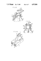
- FIGS. 1 to 5 show in combination one embodiment of the shift lever supporting apparatus according to the present invention, in which:
- FIG. 1 is a perspective view of an integral structure having a retainer portion, a shift lever mounting portion, a plate portion and a bearing portion;
- FIG. 2 is a side view of the structure shown in FIG. 1;
- FIG. 3 is a sectional view taken along the line III--III of FIG. 2;
- FIG. 4 is a vertical sectional view of the shift lever supporting apparatus.
- FIG. 5 is an exploded perspective view of the shift lever supporting apparatus.
- FIGS. 6 and 7 are sectional side views respectively showing modifications of the cap mounting structure
- FIG. 8 is a perspective view of a modification of the cap
- FIG. 9 is a vertical sectional view of the cap shown in FIG. 8 which is in its mounted state.
- FIG. 10 is a perspective view of a modification in which cable insertion bores are provided at the reverse side of the plate portion.
- FIGS. 11 to 13 show in combination a modification of the select bell-crank, in which:
- FIG. 11 is a front view of the select bell-crank
- FIG. 12 is a partly-sectioned side view of the select bell-crank.
- FIG. 13 is a sectional view taken along the line XIII--XIII of FIG. 11.
- FIGS. 14 to 16 show in combination a prior art, in which:
- FIG. 14 is a perspective view of a conventional shift lever supporting apparatus
- FIG. 15 is a vertical sectional view showing the structure for supporting the ball portion of the shift lever.
- FIG. 16 is an exploded perspective view of the conventional shift lever supporting apparatus.
- the reference numeral 1 denotes a cylindrical shift lever mounting portion for receiving the ball portion 50a of the shift lever 50, and 2 a pyramidal retainer portion contiguously provided below the shift lever mounting portion 1.
- the numeral 3 denotes a plate portion contiguously provided below the retainer portion 2, the plate portion 3 serving as a mounting portion through which the shift lever supporting apparatus is secured to the body of a vehicle.
- the numeral 4 denotes a bearing portion contiguously provided above the retainer portion 2, the bearing portion 4 facing the shift lever mounting portion 1 and serving as a portion for mounting the select bell-crank 60. These portions are formed integral with each other from a resin material by molding process.
- a part of the slant surface of the retainer portion 2 has a hat-shaped cross-sectional configuration (see FIG. 3) and reinforcing ribs 5 are provided inside the retainer portion 2 at the boundary between the shift lever mounting portion 1 and the retainer portion 2 (see FIG. 4) with a view to enhancing the overall rigidity of the supporting structure and reducing the overall weight thereof.
- a seat portion 6 for supporing the ball portion 50a of the shift lever 50 is integrally provided inside the shift lever mounting portion 1.
- a U-shaped notch 7 the upper side of which is open is provided in the wall of the shift lever mounting portion 1.
- the select lever 50b which extends sideward from the ball portion 50a is positioned within the notch 7, thereby allowing the shift lever 50 to be inserted into the shift lever mounting portion 1 from the upper side, and thus enabling the ball portion 50a to rest on the seat portion 6 (see FIG. 5).
- the ball portion 50a of the shift lever 50 is pressed at its upper half by a seat 8.
- the seat 8 is pressed at its upper end by a cap 10 through a cushion 9, the cap 10 being provided on the shift lever mounting portion 1 so as to cover the opening thereof.
- the shift lever 50 is reliably retained by the shift lever mounting portion 1.
- Boss portions 11 and 12 are formed at both ends, respectively, of the cap 10. Bores 11a and 12a are provided in the boss portions 11 and 12, respectively.
- the bearing portion 4 has a pair of projections 13 and 14 which face each other across an appropriate gap. The gap between the projections 13 and 14 is set at such a dimension that the boss portion 11 of the cap 10 can be fitted into the gap.
- the projections 13 and 14 are provided with a mutual bore 15. With the boss portion 11 fitted in the gap between the projections 13 and 14, a bell-crank shaft 16 is inserted into both the bore 11a and the bore 15, and the cap 10 is thereby attached to the bearing portion 4 (see FIG. 5).
- the bell-crank shaft 16 is jointly used to carry the select bell-crank 60 and to mount the spring 62.
- the cap 10 is retained at the gap between the projections 13 and 14 and, at the same time, the select bell-crank 60 and the spring 62 are pivotally attached to one side of the projection 14 in one unit (see FIG. 4).
- a cap securing piece 17 is provided on the upper part of the retainer portion 2 on the side thereof which is remote from the bearing portion 4 such that the cap securing piece 17 faces the bearing portion 4 across the shift lever mounting portion 1.
- the other boss portion 12 of the cap 10 is connected to the cap securing piece 17 by means of a pin 18 which is inserted through both the bore 12a and a bore 17a provided in the cap securing piece 17.
- the cap 10 has a collor portion 10a around its periphery, the collar portion 10a being fitted on the shift lever mounting portion 1.
- the mounting portion 1 has a stopper 19 provided on the outer peripheral surface thereof and in close proximity to the notch 7, the stopper 19 retaining one end of the spring 62 which biases the shift lever 50 so as to return to its neutral position.
- cable insertion bores 20 are provided in one end of the plate portion 3.
- the shift lever 50 When the shift lever 50 is to be set in the shift lever mounting portion 1, the shift lever 50 is first inserted into the mounting portion 1 and the ball portion 50a is rested on the seat portion 6 and, subsequently the seat 8 and the cushion 9 are inserted into the mounting portion 1, as shown in FIG. 1. Next, one boss portion 11 of the cap 10 is fitted into the gap between the projections 13 and 14 of the bearing portion 4 and, in this state, the bell-crank shaft 16 having both the select bell-crank 60 and the spring 62 fitted thereon is passed through both the bore 15 in the bearing portion 4 and the bore 11a in the boss portion 11, thereby connecting one end of the cap 10 to the bearing portion 4.
- the means for retaining one end of the cap 10 comprises the cap securing piece 17 and the pin 18, this securing structure is not necessarily limitative.
- the arrangement may be such that an engagement member 21 is provided at one end of the cap 10 and this engagement member 21 is engaged with a step 22 provided on the periphery of the mounting portion 1, as shown in FIG. 6.
- the arrangement may be such that a hook 23 is provided on the mounting portion 1 and this hook 23 is engaged with a recess 24 provided in the cap 10, as shown in FIG. 7.
- the cap 10 in the foregoing embodiment may be replaced with a plate clip 25 shown in FIGS. 8 and 9.
- a pair of circumferentially extending slits 26 are provided in the wall of the shift lever mounting portion 1 such that the slits 26 face each other, and the plate clip 25 is fitted into the slits 26. If the plate clip 25 is formed so as to have a curved surface in advance, when the clip 25 is in the above-described fitted state, resilient force is applied to the seat 8, so that the ball portion 50a of the shift lever 50 is reliably pressed against and thereby retained on the seat portion 6 even if the cushion 9 in the described embodiment is omitted.
- the plate portion in the foregoing embodiment may be replaced with a box-shaped plate portion 3' the lower side of which is open and which has cable insertion bores 20 provided at the reverse side thereof, as shown in FIG. 10.
- the select bell-crank may be formed into a triangular select bell-crank 60' having a window 30 from a resin material by molding process, as shown in FIGS. 11 to 13.
- an insertion bore 32 for the select lever 50b and a mounting bore 33 for the select cable securing pin 61 are provided in the vertices, respectively, of the triangular select bell-crank 60', and each pair of adjacent vertices are connected together through an arm 34.
- a bearing boss 35 is formed integral with the edge of the insertion bore 31 for the bell-crak shaft 16.
- select cable pulling force acts on the two arms in the form of either compressive force or tensile force, and the applied force is halved by the two arms, so that it is possible to form the select bell-crank 60' using a resin material by integral molding process and hence reduce the overall weight by a large margin. Since it is possible to to form the shift lever supporting apparatus by molding process using a resin material or the like, productivity is improved. In addition, the number of required parts is reduced and the assembling time is therefore shortened; therefore, productivity is further improved. At the bearing portion, it is possible to combine together a metallic shaft and a resin bearing, so that friction occurring between the shaft and the bearing is reduced and no noise is generated. Thus, the present invention provides great practical advantages.
Abstract
Description
Claims (8)
Applications Claiming Priority (6)
| Application Number | Priority Date | Filing Date | Title |
|---|---|---|---|
| JP13709987U JPH0523387Y2 (en) | 1987-09-08 | 1987-09-08 | |
| JP62-137099[U] | 1987-09-08 | ||
| JP62-137100[U]JPX | 1987-09-08 | ||
| JP13710087U JPS6443428U (en) | 1987-09-08 | 1987-09-08 | |
| JP14414987U JPS6452025U (en) | 1987-09-21 | 1987-09-21 | |
| JP63145062A JP2816468B2 (en) | 1987-09-21 | 1988-06-13 | Transmission shift lever support device |
Publications (1)
| Publication Number | Publication Date |
|---|---|
| US4873884A true US4873884A (en) | 1989-10-17 |
Family
ID=27472038
Family Applications (1)
| Application Number | Title | Priority Date | Filing Date |
|---|---|---|---|
| US07/233,034 Expired - Lifetime US4873884A (en) | 1987-09-08 | 1988-08-17 | Apparatus for supporting shift lever for transmission |
Country Status (2)
| Country | Link |
|---|---|
| US (1) | US4873884A (en) |
| DE (1) | DE3829559C5 (en) |
Cited By (20)
| Publication number | Priority date | Publication date | Assignee | Title |
|---|---|---|---|---|
| US5024117A (en) * | 1989-03-30 | 1991-06-18 | Toyota Jidosha Kabushiki Kaisha | Apparatus for supporting shift lever for transmission |
| US5182964A (en) * | 1990-02-09 | 1993-02-02 | Mercedes-Benz Ag | Change-speed gearbox hand lever connecting device |
| WO1993016428A1 (en) * | 1992-02-06 | 1993-08-19 | Dura Mechanical Components, Inc. | Simplified automatic transmission shifter |
| US5560252A (en) * | 1995-01-09 | 1996-10-01 | Kabushiki Kaisha Atsumitec | Change lever supporting structure |
| US5735177A (en) * | 1994-06-28 | 1998-04-07 | Morse Controls Limited | Remote control mechanisms |
| US5896778A (en) * | 1996-02-29 | 1999-04-27 | Fuji Kiko Co., Ltd | Operating lever device for manual transmissions for motor vehicles |
| US6374686B1 (en) * | 1996-08-13 | 2002-04-23 | Bevan Weston | Transmission and shift mechanism |
| US20030213326A1 (en) * | 2002-05-14 | 2003-11-20 | Fett Brian W. | Cable-operated transmission shifters |
| FR2845041A1 (en) * | 2002-09-30 | 2004-04-02 | Dura France | Motor vehicle gearbox control lever support housing is made in two half-shells with connectors and fixings along lengthwise plane of symmetry |
| EP1604871A1 (en) * | 1998-11-20 | 2005-12-14 | Honda Giken Kogyo Kabushiki Kaisha | Impact energy absorption structure for a shifting device of vehicle transmission |
| US20100270456A1 (en) * | 2009-04-28 | 2010-10-28 | Automotive Components Holdings, Llc | Console Retainer with Integrated Shifter Retention |
| US20110314948A1 (en) * | 2008-12-22 | 2011-12-29 | Bernd Schulze | Shift fork |
| CN101085600B (en) * | 2006-06-08 | 2012-10-03 | 万能工业株式会社 | Gear lever device |
| US20130228035A1 (en) * | 2010-07-21 | 2013-09-05 | Cnh America Llc | Operating mechanism for a bowden cable |
| USD702165S1 (en) | 2013-01-17 | 2014-04-08 | Daniel Geberth | Floor shifter |
| EP2754922A1 (en) * | 2013-01-10 | 2014-07-16 | Kongsberg Driveline Systems SAS | Shifter assembly having a biased bushing |
| US9003917B2 (en) | 2012-02-24 | 2015-04-14 | Dg Auto Sales And Service Llc | Adjustable shifter mechanism |
| US9403433B1 (en) * | 2015-03-30 | 2016-08-02 | Nissan North America, Inc. | Shifter cable assembly of a vehicle |
| US9902264B2 (en) * | 2014-03-26 | 2018-02-27 | Kabushiki Kaisha Tokai Rika Denki Seisakusho | Lever device |
| CN110822074A (en) * | 2018-08-14 | 2020-02-21 | 庆昌产业株式会社 | Gear lever device |
Families Citing this family (14)
| Publication number | Priority date | Publication date | Assignee | Title |
|---|---|---|---|---|
| FR2676843B1 (en) * | 1991-05-21 | 1993-10-01 | Systemes Blg | MANUAL CONTROL DEVICE FOR REMOTE CONTROL BY FLEXIBLE CABLES, PARTICULARLY FOR CONTROLLING THE SPEED CHANGE OF A GEARBOX. |
| US5372051A (en) * | 1992-12-14 | 1994-12-13 | Tsuda Kogyo Kabushiki Kaisha | Shift lever assembly for power transmission of automotive vehicle |
| CA2140420A1 (en) * | 1994-02-10 | 1995-08-11 | Andrew K. Ruiter | Transmission shifter |
| FR2725162A1 (en) * | 1994-09-30 | 1996-04-05 | Systeco Sa | RETURN ELEMENT FOR REPORTING CHANGE MECHANISM IN A GEARBOX FOR MOTOR VEHICLES |
| FR2725164A1 (en) * | 1994-09-30 | 1996-04-05 | Systeco Sa | DEVICE FOR TRANSMITTING THE MOVEMENTS OF A CONTROL BAR FOR A GEARBOX |
| BR7401842U (en) * | 1994-10-19 | 1995-03-21 | Paolo Paparoni | Arrangement introduced in articulation mechanism for automotive gear lever with cable drive. |
| IT1276393B1 (en) * | 1995-06-16 | 1997-10-31 | Roltra Morse Spa | COMMAND DEVICE FOR A VEHICLE SPEED CHANGE |
| IT1276394B1 (en) * | 1995-06-16 | 1997-10-31 | Roltra Morse Spa | COMMAND DEVICE FOR A VEHICLE SPEED CHANGE |
| IT1288724B1 (en) * | 1996-10-04 | 1998-09-24 | Roltra Morse Spa | CONTROL DEVICE FOR A VEHICLE SPEED CHANGE AND RELATED ASSEMBLY METHOD. |
| DE19706715A1 (en) * | 1997-02-20 | 1998-08-27 | Volkswagen Ag | Bearing housing for a gear shift device |
| DE10239173B4 (en) * | 2002-08-21 | 2005-12-22 | ZF Lemförder Metallwaren AG | Circuit device for a motor vehicle transmission with clamping device for resiliently securing the bearing bushes of a crosspiece |
| DE102004056777A1 (en) * | 2004-11-24 | 2006-06-01 | Volkswagen Ag | Gear-changing unit comprises at least one component which accommodates one of the bearing journals, and is produced as an injection molded item consisting of a plastic material hardenable by heat |
| FR2913947B1 (en) * | 2007-03-19 | 2009-10-23 | Peugeot Citroen Automobiles Sa | METHOD FOR MOUNTING A HIGH-POSITION GEARBOX CONTROL FOR A VEHICLE, AND DEVICE FOR IMPLEMENTING SUCH A METHOD |
| KR102614136B1 (en) * | 2016-10-21 | 2023-12-14 | 현대자동차주식회사 | Shift lever housing apparatus for manual transmission |
Citations (15)
| Publication number | Priority date | Publication date | Assignee | Title |
|---|---|---|---|---|
| FR859997A (en) * | 1938-07-23 | 1941-01-03 | Daimler Benz Ag | Clutch device, in particular for changing the speed of motor cars |
| US2741138A (en) * | 1952-10-11 | 1956-04-10 | Elkhart Brass Mfg Co | Locking type valve |
| DE2159715A1 (en) * | 1971-12-02 | 1973-06-07 | Frisch Gmbh | LEVER LINKAGE |
| US3800909A (en) * | 1972-07-17 | 1974-04-02 | Caterpillar Tractor Co | Noise-suppressing control lever for vibration prone mechanisms |
| DE2432555A1 (en) * | 1973-07-09 | 1975-01-30 | Saab Scania Ab | SEAL FOR A CONTROL LEVER THROUGH AN OPENING IN THE FLOOR OR WALL OF A VEHICLE |
| DE2460769A1 (en) * | 1974-12-21 | 1976-07-01 | Audi Nsu Auto Union Ag | Vibration gear lever mounting - with split bearing shells mounted in housing using soft elastic ring |
| US4457188A (en) * | 1981-10-08 | 1984-07-03 | Mtd Products Inc. | Shift lever mounting assembly |
| US4569245A (en) * | 1983-12-07 | 1986-02-11 | Jsj Corporation | Drop-in type automotive transmission shifter |
| US4581951A (en) * | 1983-10-28 | 1986-04-15 | Hurst Performance, Inc. | Transmission shifter |
| US4603598A (en) * | 1983-10-13 | 1986-08-05 | Nissan Motor Co., Ltd. | Shift lever |
| US4662772A (en) * | 1985-11-08 | 1987-05-05 | Dana Corporation | Shift lever tower assembly |
| US4679957A (en) * | 1986-06-10 | 1987-07-14 | Bauer John K | Ball joint safety system |
| US4693135A (en) * | 1986-06-05 | 1987-09-15 | Wickes Manufacturing Company | Manually operable gearshift mechanism |
| US4726249A (en) * | 1985-10-19 | 1988-02-23 | Toyota Jidosha Kabushiki Kaisha | Transmission shift lever assembly |
| US4766206A (en) * | 1985-10-03 | 1988-08-23 | Ciba-Geigy Corporation | Reactive dyestuffs comprising a vinylsulfonylalkylaminocarbonyl moiety |
Family Cites Families (11)
| Publication number | Priority date | Publication date | Assignee | Title |
|---|---|---|---|---|
| US1425730A (en) * | 1921-02-21 | 1922-08-15 | Howard Ferris Whitted | Ball and socket device |
| US1796106A (en) * | 1927-10-29 | 1931-03-10 | Frank C Webb | Transmission-case cover |
| BE754410A (en) * | 1969-08-05 | 1971-01-18 | North American Rockwell | SINGLE CONTROLLER |
| US4333360A (en) * | 1980-07-03 | 1982-06-08 | Borg-Warner Corporation | Transmission shift control apparatus |
| FR2511458B1 (en) * | 1981-08-14 | 1986-09-19 | Renault | VIBRATION AND NOISE FILTERING DEVICE |
| JPS58154023A (en) * | 1982-03-09 | 1983-09-13 | Nissan Motor Co Ltd | Vibration insulating device of variable speed controlling lever |
| JPS5958832U (en) * | 1982-10-04 | 1984-04-17 | トヨタ自動車株式会社 | Select return device of shift and select mechanism |
| JPS61203834U (en) * | 1985-06-12 | 1986-12-22 | ||
| JPS61203835U (en) * | 1985-06-13 | 1986-12-22 | ||
| DE8704164U1 (en) * | 1987-03-19 | 1987-04-30 | Skf Gleitlager Gmbh, 6625 Puettlingen, De | |
| JP2583466Y2 (en) * | 1993-02-24 | 1998-10-22 | 富士重工業株式会社 | Fuel efficiency display for vehicles with continuously variable transmission |
-
1988
- 1988-08-17 US US07/233,034 patent/US4873884A/en not_active Expired - Lifetime
- 1988-08-31 DE DE3829559A patent/DE3829559C5/en not_active Expired - Lifetime
Patent Citations (15)
| Publication number | Priority date | Publication date | Assignee | Title |
|---|---|---|---|---|
| FR859997A (en) * | 1938-07-23 | 1941-01-03 | Daimler Benz Ag | Clutch device, in particular for changing the speed of motor cars |
| US2741138A (en) * | 1952-10-11 | 1956-04-10 | Elkhart Brass Mfg Co | Locking type valve |
| DE2159715A1 (en) * | 1971-12-02 | 1973-06-07 | Frisch Gmbh | LEVER LINKAGE |
| US3800909A (en) * | 1972-07-17 | 1974-04-02 | Caterpillar Tractor Co | Noise-suppressing control lever for vibration prone mechanisms |
| DE2432555A1 (en) * | 1973-07-09 | 1975-01-30 | Saab Scania Ab | SEAL FOR A CONTROL LEVER THROUGH AN OPENING IN THE FLOOR OR WALL OF A VEHICLE |
| DE2460769A1 (en) * | 1974-12-21 | 1976-07-01 | Audi Nsu Auto Union Ag | Vibration gear lever mounting - with split bearing shells mounted in housing using soft elastic ring |
| US4457188A (en) * | 1981-10-08 | 1984-07-03 | Mtd Products Inc. | Shift lever mounting assembly |
| US4603598A (en) * | 1983-10-13 | 1986-08-05 | Nissan Motor Co., Ltd. | Shift lever |
| US4581951A (en) * | 1983-10-28 | 1986-04-15 | Hurst Performance, Inc. | Transmission shifter |
| US4569245A (en) * | 1983-12-07 | 1986-02-11 | Jsj Corporation | Drop-in type automotive transmission shifter |
| US4766206A (en) * | 1985-10-03 | 1988-08-23 | Ciba-Geigy Corporation | Reactive dyestuffs comprising a vinylsulfonylalkylaminocarbonyl moiety |
| US4726249A (en) * | 1985-10-19 | 1988-02-23 | Toyota Jidosha Kabushiki Kaisha | Transmission shift lever assembly |
| US4662772A (en) * | 1985-11-08 | 1987-05-05 | Dana Corporation | Shift lever tower assembly |
| US4693135A (en) * | 1986-06-05 | 1987-09-15 | Wickes Manufacturing Company | Manually operable gearshift mechanism |
| US4679957A (en) * | 1986-06-10 | 1987-07-14 | Bauer John K | Ball joint safety system |
Cited By (26)
| Publication number | Priority date | Publication date | Assignee | Title |
|---|---|---|---|---|
| US5024117A (en) * | 1989-03-30 | 1991-06-18 | Toyota Jidosha Kabushiki Kaisha | Apparatus for supporting shift lever for transmission |
| US5182964A (en) * | 1990-02-09 | 1993-02-02 | Mercedes-Benz Ag | Change-speed gearbox hand lever connecting device |
| WO1993016428A1 (en) * | 1992-02-06 | 1993-08-19 | Dura Mechanical Components, Inc. | Simplified automatic transmission shifter |
| US5309783A (en) * | 1992-02-06 | 1994-05-10 | Dura Mechanical Components, Inc. | Simplified automatic transmission shifter |
| US5735177A (en) * | 1994-06-28 | 1998-04-07 | Morse Controls Limited | Remote control mechanisms |
| US5560252A (en) * | 1995-01-09 | 1996-10-01 | Kabushiki Kaisha Atsumitec | Change lever supporting structure |
| US5896778A (en) * | 1996-02-29 | 1999-04-27 | Fuji Kiko Co., Ltd | Operating lever device for manual transmissions for motor vehicles |
| US6374686B1 (en) * | 1996-08-13 | 2002-04-23 | Bevan Weston | Transmission and shift mechanism |
| EP1604871A1 (en) * | 1998-11-20 | 2005-12-14 | Honda Giken Kogyo Kabushiki Kaisha | Impact energy absorption structure for a shifting device of vehicle transmission |
| US20030213326A1 (en) * | 2002-05-14 | 2003-11-20 | Fett Brian W. | Cable-operated transmission shifters |
| FR2845041A1 (en) * | 2002-09-30 | 2004-04-02 | Dura France | Motor vehicle gearbox control lever support housing is made in two half-shells with connectors and fixings along lengthwise plane of symmetry |
| EP1405751A1 (en) * | 2002-09-30 | 2004-04-07 | Dura France | Support case for control lever of a gear box of a motor vehicle |
| CN101085600B (en) * | 2006-06-08 | 2012-10-03 | 万能工业株式会社 | Gear lever device |
| US8978505B2 (en) * | 2008-12-22 | 2015-03-17 | Koki Technik Transmission Systems Gmbh | Shift fork |
| US20110314948A1 (en) * | 2008-12-22 | 2011-12-29 | Bernd Schulze | Shift fork |
| US20100270456A1 (en) * | 2009-04-28 | 2010-10-28 | Automotive Components Holdings, Llc | Console Retainer with Integrated Shifter Retention |
| US7874603B2 (en) * | 2009-04-28 | 2011-01-25 | Automotive Components Holdings, Llc | Console retainer with integrated shifter retention |
| US20130228035A1 (en) * | 2010-07-21 | 2013-09-05 | Cnh America Llc | Operating mechanism for a bowden cable |
| US9268353B2 (en) * | 2010-07-21 | 2016-02-23 | Cnh Industrial America Llc | Operating mechanism for a Bowden cable |
| US9003917B2 (en) | 2012-02-24 | 2015-04-14 | Dg Auto Sales And Service Llc | Adjustable shifter mechanism |
| EP2754922A1 (en) * | 2013-01-10 | 2014-07-16 | Kongsberg Driveline Systems SAS | Shifter assembly having a biased bushing |
| USD702165S1 (en) | 2013-01-17 | 2014-04-08 | Daniel Geberth | Floor shifter |
| US9902264B2 (en) * | 2014-03-26 | 2018-02-27 | Kabushiki Kaisha Tokai Rika Denki Seisakusho | Lever device |
| US9403433B1 (en) * | 2015-03-30 | 2016-08-02 | Nissan North America, Inc. | Shifter cable assembly of a vehicle |
| CN110822074A (en) * | 2018-08-14 | 2020-02-21 | 庆昌产业株式会社 | Gear lever device |
| CN110822074B (en) * | 2018-08-14 | 2021-07-20 | 庆昌产业株式会社 | Gear lever device |
Also Published As
| Publication number | Publication date |
|---|---|
| DE3829559C5 (en) | 2007-07-26 |
| DE3829559C2 (en) | 1996-02-29 |
| DE3829559A1 (en) | 1989-04-06 |
Similar Documents
| Publication | Publication Date | Title |
|---|---|---|
| US4873884A (en) | Apparatus for supporting shift lever for transmission | |
| US5560253A (en) | Shift lever assembly for manual transmission | |
| EP0952288B1 (en) | Locking device | |
| JPH0639006Y2 (en) | Inside handle device for vehicle | |
| US4899614A (en) | Pedal Pad | |
| JP2979079B2 (en) | Mounting structure for interior materials for automobiles | |
| JP2718913B2 (en) | Shoulder anchor adjuster for seat belt | |
| JPH0558158A (en) | Side door structure | |
| JP3419981B2 (en) | Shift lever device | |
| JPH06174060A (en) | Lever main body of transmission lever for automatic transmission | |
| JPS626899Y2 (en) | ||
| JPH045802Y2 (en) | ||
| JPH0623656Y2 (en) | Door handle device for automobile | |
| JPS5922207Y2 (en) | Automotive inside handle | |
| JPH0453482Y2 (en) | ||
| JPH0223728B2 (en) | ||
| JP2982269B2 (en) | Change lever boot device | |
| JPH0523387Y2 (en) | ||
| JPH0635081Y2 (en) | Door handle device for automobile | |
| JP2522088Y2 (en) | Rod connection structure of door handle device for automobile | |
| JPH07338Y2 (en) | Pedal operation link support device | |
| JPH0694263B2 (en) | Pillar trim mounting structure for automobiles | |
| US4914972A (en) | Device incorporating three cables for controlling a mirror support for a vehicle rearview mirror | |
| JPH0531971Y2 (en) | ||
| KR200171200Y1 (en) | Console structure of a car |
Legal Events
| Date | Code | Title | Description |
|---|---|---|---|
| AS | Assignment |
Owner name: TOYOTA JIDOSHA KABUSHIKI KAISHA, 1, TOYOTA-CHO, TO Free format text: ASSIGNMENT OF ASSIGNORS INTEREST.;ASSIGNORS:YAMADA, ICHIJI;INUZUKA, YUTAKA;ICHIHARA, ISAO;AND OTHERS;REEL/FRAME:004928/0532 Effective date: 19880802 Owner name: TSUDA INDUSTRIES CO., LTD., 1-1-1, SAIWAI-CHO, KAR Free format text: ASSIGNMENT OF ASSIGNORS INTEREST.;ASSIGNORS:YAMADA, ICHIJI;INUZUKA, YUTAKA;ICHIHARA, ISAO;AND OTHERS;REEL/FRAME:004928/0532 Effective date: 19880802 Owner name: TOYOTA JIDOSHA KABUSHIKI KAISHA, JAPAN Free format text: ASSIGNMENT OF ASSIGNORS INTEREST;ASSIGNORS:YAMADA, ICHIJI;INUZUKA, YUTAKA;ICHIHARA, ISAO;AND OTHERS;REEL/FRAME:004928/0532 Effective date: 19880802 Owner name: TSUDA INDUSTRIES CO., LTD., JAPAN Free format text: ASSIGNMENT OF ASSIGNORS INTEREST;ASSIGNORS:YAMADA, ICHIJI;INUZUKA, YUTAKA;ICHIHARA, ISAO;AND OTHERS;REEL/FRAME:004928/0532 Effective date: 19880802 |
|
| FEPP | Fee payment procedure |
Free format text: PAYOR NUMBER ASSIGNED (ORIGINAL EVENT CODE: ASPN); ENTITY STATUS OF PATENT OWNER: LARGE ENTITY |
|
| STCF | Information on status: patent grant |
Free format text: PATENTED CASE |
|
| FPAY | Fee payment |
Year of fee payment: 4 |
|
| FPAY | Fee payment |
Year of fee payment: 8 |
|
| FPAY | Fee payment |
Year of fee payment: 12 |