US5002058A - Ultrasonic transducer - Google Patents
Ultrasonic transducer Download PDFInfo
- Publication number
- US5002058A US5002058A US07/340,050 US34005089A US5002058A US 5002058 A US5002058 A US 5002058A US 34005089 A US34005089 A US 34005089A US 5002058 A US5002058 A US 5002058A
- Authority
- US
- United States
- Prior art keywords
- transducers
- acoustic
- probe device
- transducer
- catheter
- Prior art date
- Legal status (The legal status is an assumption and is not a legal conclusion. Google has not performed a legal analysis and makes no representation as to the accuracy of the status listed.)
- Expired - Lifetime
Links
Images


Classifications
-
- A—HUMAN NECESSITIES
- A61—MEDICAL OR VETERINARY SCIENCE; HYGIENE
- A61B—DIAGNOSIS; SURGERY; IDENTIFICATION
- A61B8/00—Diagnosis using ultrasonic, sonic or infrasonic waves
- A61B8/12—Diagnosis using ultrasonic, sonic or infrasonic waves in body cavities or body tracts, e.g. by using catheters
-
- A—HUMAN NECESSITIES
- A61—MEDICAL OR VETERINARY SCIENCE; HYGIENE
- A61B—DIAGNOSIS; SURGERY; IDENTIFICATION
- A61B5/00—Measuring for diagnostic purposes; Identification of persons
- A61B5/06—Devices, other than using radiation, for detecting or locating foreign bodies ; determining position of probes within or on the body of the patient
- A61B5/061—Determining position of a probe within the body employing means separate from the probe, e.g. sensing internal probe position employing impedance electrodes on the surface of the body
- A61B5/062—Determining position of a probe within the body employing means separate from the probe, e.g. sensing internal probe position employing impedance electrodes on the surface of the body using magnetic field
-
- A—HUMAN NECESSITIES
- A61—MEDICAL OR VETERINARY SCIENCE; HYGIENE
- A61B—DIAGNOSIS; SURGERY; IDENTIFICATION
- A61B8/00—Diagnosis using ultrasonic, sonic or infrasonic waves
- A61B8/08—Detecting organic movements or changes, e.g. tumours, cysts, swellings
- A61B8/0833—Detecting organic movements or changes, e.g. tumours, cysts, swellings involving detecting or locating foreign bodies or organic structures
-
- A—HUMAN NECESSITIES
- A61—MEDICAL OR VETERINARY SCIENCE; HYGIENE
- A61B—DIAGNOSIS; SURGERY; IDENTIFICATION
- A61B8/00—Diagnosis using ultrasonic, sonic or infrasonic waves
- A61B8/42—Details of probe positioning or probe attachment to the patient
- A61B8/4245—Details of probe positioning or probe attachment to the patient involving determining the position of the probe, e.g. with respect to an external reference frame or to the patient
- A61B8/4254—Details of probe positioning or probe attachment to the patient involving determining the position of the probe, e.g. with respect to an external reference frame or to the patient using sensors mounted on the probe
-
- A—HUMAN NECESSITIES
- A61—MEDICAL OR VETERINARY SCIENCE; HYGIENE
- A61B—DIAGNOSIS; SURGERY; IDENTIFICATION
- A61B34/00—Computer-aided surgery; Manipulators or robots specially adapted for use in surgery
- A61B34/20—Surgical navigation systems; Devices for tracking or guiding surgical instruments, e.g. for frameless stereotaxis
- A61B2034/2046—Tracking techniques
- A61B2034/2051—Electromagnetic tracking systems
-
- A—HUMAN NECESSITIES
- A61—MEDICAL OR VETERINARY SCIENCE; HYGIENE
- A61B—DIAGNOSIS; SURGERY; IDENTIFICATION
- A61B34/00—Computer-aided surgery; Manipulators or robots specially adapted for use in surgery
- A61B34/20—Surgical navigation systems; Devices for tracking or guiding surgical instruments, e.g. for frameless stereotaxis
- A61B2034/2046—Tracking techniques
- A61B2034/2063—Acoustic tracking systems, e.g. using ultrasound
Definitions
- the present invention relates generally to electro-acoustical devices for converting electrical energy into acoustical energy and vice versa, and more particularly to a miniature transducer, an improved system utilizing such transducers for imaging internal features of various parts of a body and, a method of making such transducers.
- a single electro-acoustical device is typically used for transmitting the sounding pulses and receiving the echoes.
- the device is switched between transmit and receive modes using a TR switch.
- the latter is designed to operate so as to minimize any interference during the receive mode caused by the excitation of the electro-acoustic device during the transmit mode. For example, the instant the device stops transmitting it may continue to ring. Accordingly, in order to receive any echo signals it is important that the device be allowed to stop ringing before the device is switched to the receiving mode.
- the TR switch can be operated quickly to quench the device at the termination of the transmit mode in order to switch the device to the receive mode.
- dead space a finite time is nevertheless required to expire before the electro-acoustic device is sufficiently quiescent in order to operate in the receive mode without residual interference from the transmit mode.
- This finite time called “dead space”
- the target distance must be sufficiently large so that echoes are not received by the electro-acoustic device until after the time of the dead space has elapsed.
- the dead space therefore creates a minimum target distance at which the ranging device will operate without cross interference between the two modes and without a loss of information. This is usually not a problem for typical radar and sonar applications where target distances are well beyond the minimum distance required.
- the system disclosed in the Parent Application comprises a catheter probe that is adapted to be inserted into a part of a body, and is particularly good at providing relatively high resolution imaging data of an relatively small, predetermined portion of the body, such as a small section of a coronary artery (the catheter may also be adapted to deliver laser energy to the interior of the body part for modifying internal features thereof, e.g., removing plaque deposits from a coronary artery).
- a transducer assembly is attached to the distal end of the catheter for emitting and receiving acoustic pulses used in generating imaging information.
- Sets of imaging data are created by moving the catheter axially along and rotationally about its axis, within the body section of interest, through a series of imaging locations, while the transducer assembly is actuated to emit a train of acoustic pulses and responsively receive a series of acoustic echoes at each imaging location.
- the transducer assembly is actuated to emit a train of acoustic pulses and responsively receive a series of acoustic echoes at each imaging location.
- acoustic interference such as acoustic cross talk
- certain electrical interference problems can occur between the transmitting and receiving devices which do not occur with a single device, such as capacitive and inductive coupling between the two devices.
- Still another object of the present is to provide an improved electro-acoustic device constructed and mounted to be substantially acoustically and electrically isolated, so that two such devices can be used respectively as transmitting and receiving devices in relatively close proximity to one another for use in a relatively close range ranging system, such as the system described in the Parent Application.
- Yet another object of the present invention is to provide an improved electro-acoustic device constructed and mounted so as to substantially reduce the amount of ringing of the device following the transmission of an acoustic pulse, and substantially prevent the generation of stray electric fields.
- Still another object of the present invention is to provide a method of making such a transducer.
- Yet another object of the present invention is to provide a catheter probe including a transmitter electro-acoustic transducer and a receiver electro-acoustic transducer so that extremely close objects can be imaged in accordance with the system described in the Parent Application;
- Still another object of the present invention is to provide such a catheter of the type described in the Parent Application in which the acoustic pulses are transmitted and received by a pair of transducer devices which are substantially acoustically and electrically isolated from one another.
- a novel miniature electro-acoustic transducer a novel method of making the transducer, and an improved catheter probe having a pair of such transducers for generating acoustic information used to image internal features of a body part.
- the transducer has a novel coaxial and closed electrical cavity construction for electrically shielding the transducer.
- the transducer is designed for use in pairs on an imaging system catheter of the type described in the Parent Application.
- a pair of the transducers of the present invention are mounted on the distal end of the catheter in such a manner so as to minimize acoustic interference between the transducers.
- the invention accordingly comprises the processes involving the several steps and the relation and order of one or more of such steps with respect to each of the others, the product possessing the features, properties and relation of components, and the apparatus possessing the construction, combination of elements and arrangement of parts, all of which are exemplified in the following detailed disclosure, and the scope of the application of which will be indicated in the claims.
- FIG. 1 is a perspective view of the preferred embodiment of the transducer of the present invention, partially broken away to expose internal features thereof;
- FIGS. 2-8 are schematic, perspective views of successive intermediate products provided in successive steps of the preferred process of fabricating the transducer shown in FIG. 1;
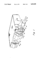
- FIG. 9 is a perspective view of the tip portion of the distal end of the catheter of the type used in the imaging system described in the Parent Application, and incorporating the present invention.
- FIG. 10 is a side elevation view of the tip portion of the catheter shown in FIG. 9.
- the preferred embodiment of the transducer of the present invention is illustrated in FIG. 1.
- the transducer comprises an inner core or substrate 20 and a piezoelectric device 32 disposed on the substrate.
- the transducer is constructed so that it is electrically shielded such that two such transducers are capable of operating adjacent one another, with one transducer operating as a transmitting device and the other as a receiver device without significant electrical interference.
- the two transducers can be suitably mounted on a catheter 100 (as described in greater detail hereinafter with respect to FIGS. 9 and 10) so that the two transducers are substantially acoustically isolated from one another.
- substrate 20 is preferably made from a suitable ceramic material, such as alumina, i.e., aluminum oxide.
- the substrate is shown in the drawings as a rectangular block or brick comprising a front surface 22 (FIGS. 1 and 2), a top surface 24 (FIG. 2), a left side surface 26 (FIG. 3), a right side surface 28 (FIG. 3), a bottom surface (not shown) opposite top surface 24, and a rear surface (not shown) opposite front surface 22. It should be appreciated, however, that the exact configuration of the substrate can vary depending upon the application for which the transducer is intended to be used.
- the transducer is preferably designed for use on a catheter of an imaging system of the type described in the Parent Application, the size of the transducer must be relatively small.
- the imaging system is designed to image selected portions of coronary arteries
- the substrate 20 is dimensioned so that it is thick enough to function as an acoustic reflector for the piezoelectric device 32.
- the piezoelectric device is a polymer piezoelectric device (as described hereinafter)
- the substrate is dimensioned on the order of about 0.028 inches wide, 0.038 inches long, and 0.012 inches thick, although I believe, at least in the case of alumina, the substrate can be made even thinner.
- the minimum thickness of the substrate is limited by the acoustic reflectivity of the substrate material for the piezoelectric device 32 and the acoustic impedance mismatch between the two.
- the minimum thickness is believed to be about 0.006 inches thick at which dimension the substrate still adequately functions as a reflector for acoustic energy generated by the piezoelectric device 32 disposed on the substrate. Decreasing the thickness to less than 0.006 inches reduces the ability of the substrate to reflect the acoustic energy to the point where a substrate of 0.003 inch thickness will cease to function as an adequate reflector so that substantially all of the acoustic energy transmitted by the device 32 downwardly will be transmitted through the substrate.
- the relatively small size of the transducer is made possible because of the material from which the piezoelectric device 32 is made, and more particularly, its relatively close impedance match to that of body fluids.
- the front surface 22 and top surface 24 are coated with an electrically conductive coating 30, preferably in the form of a metallized cladding, such as vapor deposited gold or a heat sintered metal cladding (such as granulated nickel), so as to provide an electrical connection between the front surface and the top surface.
- an electrically conductive coating 30 preferably in the form of a metallized cladding, such as vapor deposited gold or a heat sintered metal cladding (such as granulated nickel), so as to provide an electrical connection between the front surface and the top surface.
- coating 30 is about 0.2 mil inches thick although the thickness can vary depending upon the material and application of the transducer.
- a sheet or coating 33 of dielectric material having piezoelectric characteristics, and forming the center dielectric material of the piezoelectric device 32 is secured to coating 30 on top surface 24.
- the dielectric material may be secured, for example, with an electrically conductive epoxy, so that coating 30 forms the bottom electrode of the piezoelectric device.
- the piezoelectric material is of a type that can be applied as a coating, e.g., such as the materials described below
- the sheet can be deposited as a coating of substantial uniform thickness over the coating 30.
- the top electrode of the piezoelectric device 32 is provided when the outer coating 54 of electrically conductive material is provided over the top surface of the sheet 33.
- Sheet 33 is made of a material which preferably has an acoustic impedance that closely matches the acoustic impedance of body fluids and water, but provides a substantial impedance mismatch with the material of the substrate.
- Certain plastic or polymer piezoelectric materials such as polyvinylidene fluoride (PVDF) or similar copolymer materials such as PVF2 are satisfactory.
- PVDF polyvinylidene fluoride
- PVF2 similar copolymer materials
- the latter materials have an acoustic impedance (defined as the complex ratio of the sound pressure on a given surface to the sound flux through that surface) of about 4.3 million Rayleighs (4.3 ⁇ 10 6 kg/(m 2 s)), while the acoustic impedance of blood and other body tissues is in the order of 1.5 million Rayleighs.
- the final match between these two is accomplished by a one-quarter wave anti-reflective intervening layer of plastic film disposed over the top of the transducer.
- This is substantially close when one considers that the acoustic impedance of a PZT crystal material has an acoustic impedance in the order of 30.0 million Rayleighs.
- the reflectivity of the substrate is also a function of the acoustic impedance mismatch between the substrate and the piezoelectric device.
- Alumina has an acoustic impedance of about 40 million Rayleighs which provides a greater mismatch, and therefore is more reflective, with the polymeric materials described, then would be provided by a PZT crystal material.
- the piezoelectric device 32 can be preformed by providing a sheet 33 with electrodes previously formed respectively on its top and bottom surfaces before it is secured to the coating 30.
- a 52 micron thick polyvinylidene fluoride (PVDF) foil of the type manufactured and sold by Pennwalt Corporation of King of Prussia, Pa., under the tradename KYNAR Piezo Film, would be satisfactory.
- the inner conductor or core wire 34 of coaxial line 36 is preferably attached to front surface 22 using an electrically-conductive glue 38, e.g. a silver-filled room-temperature vulcanizable (RTV) glue, so as to be electrically connected to metallized coating 30 on front surface 22.
- the wire 34 is preferably mounted to extend substantially parallel with the top and bottom surfaces of the transducer and normally to the left and right side surfaces of the transducer.
- core wire 34 is about 0.001 inch in diameter, and because of its thinness is preferably made of a high strength electrically conductive material such as the nickel-copper alloy of the type manufactured under the trademark Monel by the International Nickel Co. Inc. of Huntington, W.
- the electrically conductive glue 38 is applied only on front surface 22, and care is taken so that the glue does not extend into contact with piezoelectric sheet 33 (or the upper electrode where the device is preformed before being mounted on the top of the substrate).
- An electrically insulating conformal coating 50 covers core wire 34, glue 38, front surface 22, left side surface 26, right side surface 28 and the back and bottom surfaces of core 20. Again care is taken so that none of the coating 50 contacts piezoelectric sheet 33 (or piezoelectric device 32, where the latter is preformed before being applied to the substrate). Coating 50 is approximately 0.003 inches thick when applied to the core wire 34 and about 0.001 inches thick when applied to the remaining surfaces around the substrate.
- the coating 50 is preferably made from a vinyl material, but other conformal materials having suitable insulative properties may also be satisfactorily employed.
- Drain wire 52 is wrapped around coating 50 on core wire 34 and is attached by suitable means to the insulative coating 50 on front surface 22. Drain wire 52 is preferably about 0.0007 inches in diameter, although the size of the wire can vary.
- An electrically-conductive coating 54 completely covers insulative coating 50, drain wire 52, as well as the piezoelectric sheet 33 (where the top surface of the sheet is exposed) so as to completely encapsulate the entire assembly with an electrical conductor.
- the upper exposed surface of the device will already be provided with an electrically conductive material so that coating 54 need only extend over the top edges of the front, rear, left and right side surfaces of the transducer so as to electrically contact the edge portions of upper exposed electrode of piezoelectric device 32.
- conductive coating 54 covers drain wire 34 and insulative coating 50 on core wire 34 (so as to form the outer conductor of the coaxial line 36).
- the conductive coating 54 (together with the upper electrode of the device 32) also encases the substrate and piezoelectric sheet 33 so as to form an electric shield as well as a conductor for providing an electrical path between the top side of the sheet 33 of the piezoelectric device 32, and the outer conductor of the coaxial line 36.
- Conductive coating 54 is preferably made from a silver-filled, RTV paint, and is preferably less than 0.001 inches thick, although other materials and thicknesses may be utilized.
- the construction of the transducer is that of an electrical cavity fed by a co-axial conduction line.
- the combination when functioning as a transmitter, will contain all electromagnetic fields introduced by way of the co-axial arrangement to the inside of the co-axial line and the electrical cavity.
- all external electromagnetic fields will be excluded from the inside of both the electrical cavity and the co-axial line, and thus, will exhibit an immunity to incidental fields.
- two such transducers are utilized together, one as a transmitter and the other as a receiver, as is contemplated in accordance with at least one aspect of the present invention, the combined effect of driver field retention or trapping and exterior field rejection results in extremely low electrical and magnetic cross talk between transmitter and receiver.
- an electrical excitation voltage preferably in the form of a train of pulses, is applied between the electrodes provided in contact with top and bottom surfaces of the piezoelectric sheet 33 (in the embodiment illustrated the top electrode is provided by the conductive coating 54 covering the sheet 33, while the bottom electrode is provided by the coating 30 provided between the top surface 24 of the substrate 20 and the bottom surface of the piezoelectric sheet 33), wherein one electrical path for applying the excitation voltage is formed by the core wire 34 of coaxial line 36, through conductive glue 38 to coating 30 on front surface 22, and in turn to coating 30 on top surface 24 (which directly contacts the lower side of the sheet 33 or directly contacts the lower electrode of the device 32, where the latter is preformed before being mounted to the substrate).
- piezoelectric sheet 33 converts electrical energy from the excitation voltage applied to the sheet to mechanical energy. More specifically, as is also well known, the application of an excitation voltage to piezoelectric material causes the latter to mechanically distort so as to generate an ultrasonic signal in a direction normal to top surface 24.
- the drain wire 52 provides a more highly conductive ground path than would be provided by the coating 54 alone.
- the wire 52 provides longitudinal conductivity while coating 54 provides lateral conductivity.
- acoustic pulses which contact piezoelectric device 32 slightly distort the device causing a potential to develop across the top and bottom electrodes (formed in the embodiment shown by coatings 54 and 30, respectively).
- the potential varies with the strength of the acoustic pulse.
- the potential generated by piezoelectric device 32 is sensed through one conductive path defined by the coating 30 on top surface 24 to side surface 22 and through conductive glue 38 to core wire 34, and through the other conductive path defined by the conductive coating 54.
- the potential will be proportional to the acoustic pulse sensed.
- FIGS. 2-8 In connection with the following description of the method of making the transducer of the present invention, reference should be made to FIGS. 2-8.
- a core or substrate 20 is provided as the starting material as shown in FIG. 2.
- the substrate is cut or otherwise formed to the required size.
- front surface 22 and top surface 24 are provided with a continuous electrically conductive layer 30.
- a metallized cladding may be used to form coating 30.
- the coating is applied to a thickness of about 0.2 mil inches.
- sheet 33 of piezoelectric material is provided in sheet form, it is applied to the layer 30 provided on top surface 24 using an electrically conductive epoxy to secure the bottom surface of the sheet 33 to the top surface of the layer 30.
- the material may be applied directly to coating 30 as a coating of piezoelectric material using well known deposition techniques.
- the bottom electrode is secured to the layer 30 with a suitable electrically conductive material, such as an electrically conductive epoxy.
- piezoelectric device has an acoustic impedance which is close to that of water and body fluids. Piezoelectric device 32 is preferably sized to cover the entire top surface 24 of the substrate when it is secured to the coating 30 on that surface.
- one end of core wire 34 is attached to electrically conductive coating 30 on front surface 22 using an electrically conductive glue 38. It is important that glue 38 be applied to front surface 22 so as not to extend into contact with piezoelectric sheet 33, or when device 32 is preformed before being mounted on the substrate, into contact with the upper surface of the piezoelectric device.
- core wire 34 and the entire transducer, except for piezoelectric sheet 33 (or device 32) is covered with an electrically insulating conformal coating 50, e.g., a vinyl coating.
- gold drain wire 34 is wrapped around the insulative coating 50 on core wire 34 and the end of the wire adjacent the transducer is attached to insulative coating 50 on front surface 22 using an electrically conductive cement.
- a layer 54 of electrically-conductive paint is applied to all four sides and the bottom of the transducer, to insulative coating 50 on core wire 34, to the drain wire 52 wrapped around the coated core wire, and where sheet 33 is applied without a top electrode, the entire top surface of the sheet 33.
- layer 54 is applied to all of the surfaces except the upper electrode, but is applied with respect to that electrode so as to extend over the side surfaces of the transducer onto peripheral edge portions of the upper electrode so as to electrically connect the electrically-conductive layer 54 on the sides and bottom of the transducer with piezoelectric device 32 and create the electrical cavity.
- Known integrated circuit chip and miniature electronic component fabrication techniques may be satisfactorily employed in the above-described method of manufacturing the transducer of the present invention.
- electrically-conductive layers 30 and 54 and insulative layer 50 may be applied using known mask and spray techniques.
- Piezoelectric sheet 33 may be applied using known vacuum workpiece positioning systems.
- a catheter probe 100 includes a pair of the transducers of the present invention and is designed for use in a system for imaging internal features of a body part, such as the system described in the Parent Application.
- the catheter probe 100 of the present invention comprises an flexible tubular body having a distal end 104 and a flat surface 106 for supporting each transducer 110 and 112.
- the flat surface extends along a portion of the length of body and is formed adjacent distal end 104.
- flat surface 106 is treated, preferably when initially formed, to provide a roughened surface so as to create dead air spaces between the catheter and each transducer 110 and 112.
- Loop 108 is attached to the body at the distal end 104.
- Loop 108 is provided as an antenna for detecting magnetic reference signals used in establishing the position of the distal end of the catheter probe 100 inside the body part being imaged.
- Catheter probe 100 further comprises transmit transducer 110 and receive transducer 112, each constructed as described with respect to FIGS. 1-8.
- the two transducers are positioned on probe 100 so the bottom surfaces of the transducers rest on the roughened surface formed on flat surface 106.
- the catheter body is formed of a high modulus nylon, such as the nylon material sold under the trademark Zitel 42
- the roughened surface 106 can be mechanically formed, for example, by using a fine grain sand paper to rub the flat surface so as to create randomly dispersed burrs 107 (FIG. 10) or irregular cuts on the surface with hanging fragments at least in the area which will support the transducers 110 and 112.
- the transducers 110 and 112 are positioned adjacent to, but spaced apart slightly, e.g., about 0.006 inches, from one another.
- the coaxial line 36a provides the excitation voltage to the transmit transducer 110, while coaxial line 36b provides signals representative of the acoustic energy sensed by receive transducer 112.
- Coaxial wires 36a and 36b are positioned to extend along the surface of the body, away from distal end 104.
- Probe 100 also comprises one or more optical waveguides 120 for transmitting laser energy toward distal end 104 to a position adjacent receive transducer 112.
- a mirror 122 is positioned between transducer 112 and the output ends 124 of waveguides 120 for directing the laser energy transmitted by waveguides 120 so as to travel in a direction substantially parallel to the direction of an axis normal to the upper surface of the transducer 112 and transverse to the axis of the catheter.
- the entire end portion of catheter probe 100 is wrapped in a thin film 102.
- the selection of material for the film 102 should have an acoustic impedance which closely approximates the geometric mean of the acoustic impedances of the transducer piezoelectric device 32 and the bodily fluids in contact with the film in order to improve the acoustic coupling between the device 32 and the fluids.
- the foregoing is easily accomplished with any one of several plastic films, with polyethylene being preferred.
- the plastic film functions as a one-quarter wave anti-reflective intervening layer of plastic material between each transducer and the body tissues disposed over the transducer at the particular location of the device.
- the preferred polyethylene film can be provided with a coating of suitable gummed adhesive on its inner surface so as to ensure the film remains in a wrapped condition.
- a wrap 128 covers the remaining portions of the catheter end not covered by the film 102 and therefore does not cover the transducers.
- Coaxial lines 36a and 36b, antenna loop 108, and optical waveguides 120 are encased in film 128 and extend away from distal end 104 of probe 100 extending along the body 102 of the catheter. These wires and optical fibers are enclosed as a bundle in a suitable casing. This encased bundle is connected to a control device (not shown) for generating the excitation voltage supplied over coaxial wire 36a to transmit transducer 110, for receiving the response signal from receive transducer 112 carried over coaxial line 36b, for generating the laser energy transmitted over optical waveguides 120, and for receiving signals over wire ends 109 from wire loop 108.
- a control device not shown
- transducers 110 and 112 be positioned as close to one another as possible so that the receive transducer 112 is positioned to receive echo pulses from relatively close targets in response to acoustic pulses generated by the transmit transducer 110.
- the electrical cavity construction of the transducer of the present invention permits transducers 110 and 112 to be mounted in side-by-side configuration, as the electrical cavity casing around the transducers substantially prevents electromagnetic fields from leaking out or entering the transducers. As such, the transducers are electromagnetically isolated from one another, with the result that there is little or no electromagnetic interference between transducers 110 and 112.
- transducers 110 and 112 be acoustically isolated from one another. Because acoustic cross talk arrives later in time than electrical cross talk, the acoustic cross talk can arrive at the receiving transducer at the same time as the echo data signals and therefore make it even more difficult to process the latter signals.
- the transmit and receive transducer 110 and 112 are mounted so as to be substantially acoustically isolated from one another because the roughened surface provides sufficient dead air space between the bottom surface of each transducer and the surface 106 so as to substantially acoustically dampen any acoustic signals which might be transmitted between the two transducers through the body 102.
- the acoustic dampening virtually eliminates any detrimental acoustic cross talk between the transducers.
- Catheter probe 100 is used in substantially the same manner as the catheter probe of the imaging system disclosed in the Parent Application. Thus, attention is directed to the Parent Application for a complete description of the manner in which probe 100 is used. Briefly, however, the distal end of the catheter probe 100 is inserted in a selected body part, e.g., a coronary artery, until the probe is positioned at an area of interest. The signals received on wire loop 108 are used in determining the radial position of probe 100. The receive transducer senses the axial position of the probe. Acoustic pulses are transmitted from transmit transducer 110 and the associated echo pulses are sensed by receive transducer 112.
- an image of the internal features of the body part can be generated.
- laser energy can transmitted along optical waveguide 120, and folded at mirror 122 so as to selectively radiate preselected portions of the portion of the body under investigation.
- This laser energy can be used, for instance, to burn away plaque deposits inside a coronary artery.
- a significant advantage of the transducer of the present invention is that two of the transducers can be positioned adjacent one another without substantially electromagnetically interfering with one another.
- the electrical isolation provided by the electrical cavity and coaxial construction of the transducers greatly reduces or eliminates electrical cross talk between the transducers.
- the transducer of the present invention is highly suited for use, in side-by-side configuration, particularly for close range ranging systems such as the system disclosed in the Parent Application.
- the two transducers can be substantially acoustically isolated from one another so as to substantially reduce the effects of acoustical cross-talk between the two transducers so that the two transducers 110 and 112 can be mounted very close to one another without interfering with one another.
- the transducers can be made miniature in size so as to fit on the distal end of the catheter probe. Consequently, the use of miniature transducers makes the use of the probe as part of the imaging system described in the Parent Application practical.
- the method of manufacturing the transducer of the present invention is designed to permit rapid and efficient fabrication of the miniature transducer, transducer for example, having miniature external dimensions in the range of 0.012"(thickness) ⁇ 0.028"(width) ⁇ 0.038"(length-along the length of the catheter).
- the transducer can be made even smaller than these dimensions with, for example, improved copolymer materials for sheet 33 providing an even closer match in acoustic impedance (so as to allow a decrease in the thickness dimension) and increased signal strength per unit area (so as to allow a decrease in the thickness dimension).
- catheter probe of the present invention as compared to known ultrasonic probes having a single transducer for transmitting and receiving acoustic pulses, is that the present catheter probe will provide accurate imaging data of internal body features at extremely close range, where in some cases the outer surface of the film 128 above the upper surface of the piezoelectric device 32, directly contacts a surface of interest.
- the minimum range of the devices is typically between about a few millimeters to 10 centimeters or so.
Abstract
Description
Claims (22)
Priority Applications (1)
| Application Number | Priority Date | Filing Date | Title |
|---|---|---|---|
| US07/340,050 US5002058A (en) | 1986-04-25 | 1989-04-18 | Ultrasonic transducer |
Applications Claiming Priority (3)
| Application Number | Priority Date | Filing Date | Title |
|---|---|---|---|
| US85662186A | 1986-04-25 | 1986-04-25 | |
| US07/151,394 US4862893A (en) | 1987-12-08 | 1988-02-02 | Ultrasonic transducer |
| US07/340,050 US5002058A (en) | 1986-04-25 | 1989-04-18 | Ultrasonic transducer |
Related Parent Applications (1)
| Application Number | Title | Priority Date | Filing Date |
|---|---|---|---|
| US07/151,394 Division US4862893A (en) | 1986-04-25 | 1988-02-02 | Ultrasonic transducer |
Publications (1)
| Publication Number | Publication Date |
|---|---|
| US5002058A true US5002058A (en) | 1991-03-26 |
Family
ID=27387112
Family Applications (1)
| Application Number | Title | Priority Date | Filing Date |
|---|---|---|---|
| US07/340,050 Expired - Lifetime US5002058A (en) | 1986-04-25 | 1989-04-18 | Ultrasonic transducer |
Country Status (1)
| Country | Link |
|---|---|
| US (1) | US5002058A (en) |
Cited By (128)
| Publication number | Priority date | Publication date | Assignee | Title |
|---|---|---|---|---|
| US5070882A (en) * | 1988-03-28 | 1991-12-10 | Telectronics Pacing Systems, Inc. | Probe tip ultrasonic transducers and method of manufacture |
| US5109861A (en) * | 1989-04-28 | 1992-05-05 | Thomas Jefferson University | Intravascular, ultrasonic imaging catheters and methods for making same |
| US5144955A (en) * | 1991-04-15 | 1992-09-08 | Cordis Corporation | Doppler velocity measuring medical unit |
| US5176140A (en) * | 1989-08-14 | 1993-01-05 | Olympus Optical Co., Ltd. | Ultrasonic probe |
| US5228176A (en) * | 1988-03-28 | 1993-07-20 | Telectronics Pacing Systems, Inc. | Method of manufacture of probe tip ultrasonic transducer |
| US5240004A (en) * | 1989-04-28 | 1993-08-31 | Thomas Jefferson University | Intravascular, ultrasonic imaging catheters and methods for making same |
| US5242386A (en) * | 1992-08-27 | 1993-09-07 | Sontech Limited | Echographic suction cannula |
| US5348017A (en) * | 1993-01-19 | 1994-09-20 | Cardiovascular Imaging Systems, Inc. | Drive shaft for an intravascular catheter system |
| US5406951A (en) * | 1993-10-15 | 1995-04-18 | Ten Hoff; Harm | Intra-luminal ultrasonic instrument |
| US5423319A (en) * | 1994-06-15 | 1995-06-13 | Hewlett-Packard Company | Integrated impedance matching layer to acoustic boundary problems for clinical ultrasonic transducers |
| US5620479A (en) * | 1992-11-13 | 1997-04-15 | The Regents Of The University Of California | Method and apparatus for thermal therapy of tumors |
| US5733315A (en) * | 1992-11-13 | 1998-03-31 | Burdette; Everette C. | Method of manufacture of a transurethral ultrasound applicator for prostate gland thermal therapy |
| US5807268A (en) * | 1992-09-09 | 1998-09-15 | Medacoustics, Inc. | Disposable sensing device with contaneous conformance |
| US6104944A (en) * | 1997-11-17 | 2000-08-15 | Martinelli; Michael A. | System and method for navigating a multiple electrode catheter |
| US6193668B1 (en) | 1997-11-10 | 2001-02-27 | Medacoustics, Inc. | Acoustic sensor array for non-invasive detection of coronary artery disease |
| US6243599B1 (en) | 1997-11-10 | 2001-06-05 | Medacoustics, Inc. | Methods, systems and computer program products for photogrammetric sensor position estimation |
| US6261237B1 (en) | 1998-08-20 | 2001-07-17 | Medacoustics, Inc. | Thin film piezoelectric polymer sensor |
| US20020042565A1 (en) * | 1999-08-05 | 2002-04-11 | Cooper Joel D. | Conduits for maintaining openings in tissue |
| US6374134B1 (en) | 1992-08-14 | 2002-04-16 | British Telecommunications Public Limited Company | Simultaneous display during surgical navigation |
| US20020111620A1 (en) * | 2001-02-14 | 2002-08-15 | Broncus Technologies, Inc. | Devices and methods for maintaining collateral channels in tissue |
| US20020138074A1 (en) * | 1999-08-05 | 2002-09-26 | Thomas Keast | Devices for applying energy to tissue |
| US6493573B1 (en) | 1999-10-28 | 2002-12-10 | Winchester Development Associates | Method and system for navigating a catheter probe in the presence of field-influencing objects |
| US20030028091A1 (en) * | 2000-04-07 | 2003-02-06 | Simon David Anthony | Trajectory storage apparatus and method for surgical navigation systems |
| US20030114752A1 (en) * | 1999-04-20 | 2003-06-19 | Jaimie Henderson | Instrument guidance method and system for image guided surgery |
| US6701179B1 (en) | 1999-10-28 | 2004-03-02 | Michael A. Martinelli | Coil structures and methods for generating magnetic fields |
| US6712812B2 (en) | 1999-08-05 | 2004-03-30 | Broncus Technologies, Inc. | Devices for creating collateral channels |
| US20040073155A1 (en) * | 2000-01-14 | 2004-04-15 | Broncus Technologies, Inc. | Methods and devices for maintaining patency of surgically created channels in tissue |
| US6747539B1 (en) | 1999-10-28 | 2004-06-08 | Michael A. Martinelli | Patient-shielding and coil system |
| US6749606B2 (en) | 1999-08-05 | 2004-06-15 | Thomas Keast | Devices for creating collateral channels |
| US6757557B1 (en) | 1992-08-14 | 2004-06-29 | British Telecommunications | Position location system |
| US20040147811A1 (en) * | 2001-12-14 | 2004-07-29 | Diederich Chris J | Catheter based balloon for therapy modification and positioning of tissue |
| US20040171924A1 (en) * | 2003-01-30 | 2004-09-02 | Mire David A. | Method and apparatus for preplanning a surgical procedure |
| US20040193057A1 (en) * | 2003-03-28 | 2004-09-30 | Scimed Life Systems, Inc. | Imaging transducer assembly |
| US20040201926A1 (en) * | 2003-04-08 | 2004-10-14 | Seagate Technologies Llc | Encapsulant for a disc drive component |
| US20040215071A1 (en) * | 2003-04-25 | 2004-10-28 | Frank Kevin J. | Method and apparatus for performing 2D to 3D registration |
| US20050049486A1 (en) * | 2003-08-28 | 2005-03-03 | Urquhart Steven J. | Method and apparatus for performing stereotactic surgery |
| US20050060042A1 (en) * | 2001-09-04 | 2005-03-17 | Broncus Technologies, Inc. | Methods and devices for maintaining surgically created channels in a body organ |
| US20050060044A1 (en) * | 1999-08-05 | 2005-03-17 | Ed Roschak | Methods and devices for maintaining patency of surgically created channels in a body organ |
| US20050085716A1 (en) * | 2003-10-20 | 2005-04-21 | Scimed Life Systems, Inc. | Transducer/sensor assembly |
| US20050085715A1 (en) * | 2003-10-17 | 2005-04-21 | Dukesherer John H. | Method and apparatus for surgical navigation |
| US6892090B2 (en) | 2002-08-19 | 2005-05-10 | Surgical Navigation Technologies, Inc. | Method and apparatus for virtual endoscopy |
| US20050107783A1 (en) * | 1999-08-05 | 2005-05-19 | Broncus Technologies, Inc. | Devices for applying energy to tissue |
| US20050137611A1 (en) * | 2001-09-04 | 2005-06-23 | Broncus Technologies, Inc. | Methods and devices for maintaining surgically created channels in a body organ |
| US20050137518A1 (en) * | 2002-04-19 | 2005-06-23 | Broncus Technologies, Inc. | Devices for maintaining surgically created openings |
| US20050137715A1 (en) * | 1999-08-05 | 2005-06-23 | Broncus Technologies, Inc. | Methods and devices for maintaining patency of surgically created channels in a body organ |
| US6930861B2 (en) | 2003-04-08 | 2005-08-16 | Seagate Technology Llc | Encapsulant for microactuator suspension |
| US6947786B2 (en) | 2002-02-28 | 2005-09-20 | Surgical Navigation Technologies, Inc. | Method and apparatus for perspective inversion |
| US6968224B2 (en) | 1999-10-28 | 2005-11-22 | Surgical Navigation Technologies, Inc. | Method of detecting organ matter shift in a patient |
| US20050277832A1 (en) * | 1997-09-24 | 2005-12-15 | Foley Kevin T | Percutaneous registration apparatus and method for use in computer-assisted surgical navigation |
| US7007699B2 (en) | 1999-10-28 | 2006-03-07 | Surgical Navigation Technologies, Inc. | Surgical sensor |
| US20060094958A1 (en) * | 2004-10-28 | 2006-05-04 | Marquart Joel G | Method and apparatus for calibrating non-linear instruments |
| US7085400B1 (en) | 2000-06-14 | 2006-08-01 | Surgical Navigation Technologies, Inc. | System and method for image based sensor calibration |
| US7130676B2 (en) | 1998-08-20 | 2006-10-31 | Sofamor Danek Holdings, Inc. | Fluoroscopic image guided orthopaedic surgery system with intraoperative registration |
| US20060280773A1 (en) * | 1999-08-05 | 2006-12-14 | Broncus Technologies, Inc. | Methods and devices for maintaining patency of surgically created channels in a body organ |
| US20060280772A1 (en) * | 2001-09-04 | 2006-12-14 | Broncus Technologies, Inc. | Methods and devices for maintaining surgically created channels in a body organ |
| US20060278247A1 (en) * | 1999-10-28 | 2006-12-14 | Mark W. Hunter Et Al. | Surgical communication and power system |
| US20070042154A1 (en) * | 2003-04-08 | 2007-02-22 | Seagate Technology Llc | Self-assembled monolayer enhanced DLC coatings |
| US20070196673A1 (en) * | 2006-02-17 | 2007-08-23 | Seagate Technology Llc | Lubricative and protective thin film |
| US7422563B2 (en) | 1999-08-05 | 2008-09-09 | Broncus Technologies, Inc. | Multifunctional tip catheter for applying energy to tissue and detecting the presence of blood flow |
| US7462162B2 (en) | 2001-09-04 | 2008-12-09 | Broncus Technologies, Inc. | Antiproliferative devices for maintaining patency of surgically created channels in a body organ |
| USRE40852E1 (en) | 1995-06-14 | 2009-07-14 | Medtronic Navigation, Inc. | Method and system for navigating a catheter probe |
| US7657300B2 (en) | 1999-10-28 | 2010-02-02 | Medtronic Navigation, Inc. | Registration of human anatomy integrated for electromagnetic localization |
| US7660623B2 (en) | 2003-01-30 | 2010-02-09 | Medtronic Navigation, Inc. | Six degree of freedom alignment display for medical procedures |
| US7697972B2 (en) | 2002-11-19 | 2010-04-13 | Medtronic Navigation, Inc. | Navigation system for cardiac therapies |
| US7708712B2 (en) | 2001-09-04 | 2010-05-04 | Broncus Technologies, Inc. | Methods and devices for maintaining patency of surgically created channels in a body organ |
| US7763035B2 (en) | 1997-12-12 | 2010-07-27 | Medtronic Navigation, Inc. | Image guided spinal surgery guide, system and method for use thereof |
| US7835784B2 (en) | 2005-09-21 | 2010-11-16 | Medtronic Navigation, Inc. | Method and apparatus for positioning a reference frame |
| US7835778B2 (en) | 2003-10-16 | 2010-11-16 | Medtronic Navigation, Inc. | Method and apparatus for surgical navigation of a multiple piece construct for implantation |
| US7840253B2 (en) | 2003-10-17 | 2010-11-23 | Medtronic Navigation, Inc. | Method and apparatus for surgical navigation |
| US7881770B2 (en) | 2000-03-01 | 2011-02-01 | Medtronic Navigation, Inc. | Multiple cannula image guided tool for image guided procedures |
| US20110054293A1 (en) * | 2009-08-31 | 2011-03-03 | Medtronic, Inc. | Combination Localization System |
| US7953471B2 (en) | 2004-05-03 | 2011-05-31 | Medtronic Navigation, Inc. | Method and apparatus for implantation between two vertebral bodies |
| US7996064B2 (en) | 1999-03-23 | 2011-08-09 | Medtronic Navigation, Inc. | System and method for placing and determining an appropriately sized surgical implant |
| US7998062B2 (en) | 2004-03-29 | 2011-08-16 | Superdimension, Ltd. | Endoscope structures and techniques for navigating to a target in branched structure |
| US8025688B2 (en) | 1992-11-13 | 2011-09-27 | The Regents Of The University Of California | Apparatus for thermal therapy of prostate gland with ultrasound energy |
| US8060185B2 (en) | 2002-11-19 | 2011-11-15 | Medtronic Navigation, Inc. | Navigation system for cardiac therapies |
| US8112292B2 (en) | 2006-04-21 | 2012-02-07 | Medtronic Navigation, Inc. | Method and apparatus for optimizing a therapy |
| USRE43328E1 (en) | 1997-11-20 | 2012-04-24 | Medtronic Navigation, Inc | Image guided awl/tap/screwdriver |
| US8165658B2 (en) | 2008-09-26 | 2012-04-24 | Medtronic, Inc. | Method and apparatus for positioning a guide relative to a base |
| US8175681B2 (en) | 2008-12-16 | 2012-05-08 | Medtronic Navigation Inc. | Combination of electromagnetic and electropotential localization |
| US8239001B2 (en) | 2003-10-17 | 2012-08-07 | Medtronic Navigation, Inc. | Method and apparatus for surgical navigation |
| USRE43952E1 (en) | 1989-10-05 | 2013-01-29 | Medtronic Navigation, Inc. | Interactive system for local intervention inside a non-homogeneous structure |
| US8409167B2 (en) | 2004-07-19 | 2013-04-02 | Broncus Medical Inc | Devices for delivering substances through an extra-anatomic opening created in an airway |
| US8452068B2 (en) | 2008-06-06 | 2013-05-28 | Covidien Lp | Hybrid registration method |
| US8473032B2 (en) | 2008-06-03 | 2013-06-25 | Superdimension, Ltd. | Feature-based registration method |
| US8494613B2 (en) | 2009-08-31 | 2013-07-23 | Medtronic, Inc. | Combination localization system |
| US8611984B2 (en) | 2009-04-08 | 2013-12-17 | Covidien Lp | Locatable catheter |
| US8644907B2 (en) | 1999-10-28 | 2014-02-04 | Medtronic Navigaton, Inc. | Method and apparatus for surgical navigation |
| US8660635B2 (en) | 2006-09-29 | 2014-02-25 | Medtronic, Inc. | Method and apparatus for optimizing a computer assisted surgical procedure |
| US8663088B2 (en) | 2003-09-15 | 2014-03-04 | Covidien Lp | System of accessories for use with bronchoscopes |
| US8709034B2 (en) | 2011-05-13 | 2014-04-29 | Broncus Medical Inc. | Methods and devices for diagnosing, monitoring, or treating medical conditions through an opening through an airway wall |
| US8764725B2 (en) | 2004-02-09 | 2014-07-01 | Covidien Lp | Directional anchoring mechanism, method and applications thereof |
| US8838199B2 (en) | 2002-04-04 | 2014-09-16 | Medtronic Navigation, Inc. | Method and apparatus for virtual digital subtraction angiography |
| US8905920B2 (en) | 2007-09-27 | 2014-12-09 | Covidien Lp | Bronchoscope adapter and method |
| US8932207B2 (en) | 2008-07-10 | 2015-01-13 | Covidien Lp | Integrated multi-functional endoscopic tool |
| US9055881B2 (en) | 2004-04-26 | 2015-06-16 | Super Dimension Ltd. | System and method for image-based alignment of an endoscope |
| US9168102B2 (en) | 2006-01-18 | 2015-10-27 | Medtronic Navigation, Inc. | Method and apparatus for providing a container to a sterile environment |
| US9345532B2 (en) | 2011-05-13 | 2016-05-24 | Broncus Medical Inc. | Methods and devices for ablation of tissue |
| US9533128B2 (en) | 2003-07-18 | 2017-01-03 | Broncus Medical Inc. | Devices for maintaining patency of surgically created channels in tissue |
| US9575140B2 (en) | 2008-04-03 | 2017-02-21 | Covidien Lp | Magnetic interference detection system and method |
| US9675424B2 (en) | 2001-06-04 | 2017-06-13 | Surgical Navigation Technologies, Inc. | Method for calibrating a navigation system |
| US10111704B2 (en) | 2002-09-30 | 2018-10-30 | Relievant Medsystems, Inc. | Intraosseous nerve treatment |
| US10265099B2 (en) | 2008-09-26 | 2019-04-23 | Relievant Medsystems, Inc. | Systems for accessing nerves within bone |
| US10272260B2 (en) | 2011-11-23 | 2019-04-30 | Broncus Medical Inc. | Methods and devices for diagnosing, monitoring, or treating medical conditions through an opening through an airway wall |
| US10357258B2 (en) | 2012-11-05 | 2019-07-23 | Relievant Medsystems, Inc. | Systems and methods for creating curved paths through bone |
| US10390877B2 (en) | 2011-12-30 | 2019-08-27 | Relievant Medsystems, Inc. | Systems and methods for treating back pain |
| US10418705B2 (en) | 2016-10-28 | 2019-09-17 | Covidien Lp | Electromagnetic navigation antenna assembly and electromagnetic navigation system including the same |
| US10426555B2 (en) | 2015-06-03 | 2019-10-01 | Covidien Lp | Medical instrument with sensor for use in a system and method for electromagnetic navigation |
| US10446931B2 (en) | 2016-10-28 | 2019-10-15 | Covidien Lp | Electromagnetic navigation antenna assembly and electromagnetic navigation system including the same |
| US10456187B2 (en) | 2013-08-08 | 2019-10-29 | Relievant Medsystems, Inc. | Modulating nerves within bone using bone fasteners |
| US10463423B2 (en) | 2003-03-28 | 2019-11-05 | Relievant Medsystems, Inc. | Thermal denervation devices and methods |
| US10478254B2 (en) | 2016-05-16 | 2019-11-19 | Covidien Lp | System and method to access lung tissue |
| US10517505B2 (en) | 2016-10-28 | 2019-12-31 | Covidien Lp | Systems, methods, and computer-readable media for optimizing an electromagnetic navigation system |
| US10582834B2 (en) | 2010-06-15 | 2020-03-10 | Covidien Lp | Locatable expandable working channel and method |
| US10588691B2 (en) | 2012-09-12 | 2020-03-17 | Relievant Medsystems, Inc. | Radiofrequency ablation of tissue within a vertebral body |
| US10615500B2 (en) | 2016-10-28 | 2020-04-07 | Covidien Lp | System and method for designing electromagnetic navigation antenna assemblies |
| US10638952B2 (en) | 2016-10-28 | 2020-05-05 | Covidien Lp | Methods, systems, and computer-readable media for calibrating an electromagnetic navigation system |
| US10722311B2 (en) | 2016-10-28 | 2020-07-28 | Covidien Lp | System and method for identifying a location and/or an orientation of an electromagnetic sensor based on a map |
| US10751126B2 (en) | 2016-10-28 | 2020-08-25 | Covidien Lp | System and method for generating a map for electromagnetic navigation |
| US10792106B2 (en) | 2016-10-28 | 2020-10-06 | Covidien Lp | System for calibrating an electromagnetic navigation system |
| US10905440B2 (en) | 2008-09-26 | 2021-02-02 | Relievant Medsystems, Inc. | Nerve modulation systems |
| USRE48460E1 (en) | 2002-09-30 | 2021-03-09 | Relievant Medsystems, Inc. | Method of treating an intraosseous nerve |
| US10952593B2 (en) | 2014-06-10 | 2021-03-23 | Covidien Lp | Bronchoscope adapter |
| US11007010B2 (en) | 2019-09-12 | 2021-05-18 | Relevant Medsysterns, Inc. | Curved bone access systems |
| US11006914B2 (en) | 2015-10-28 | 2021-05-18 | Medtronic Navigation, Inc. | Apparatus and method for maintaining image quality while minimizing x-ray dosage of a patient |
| US11219489B2 (en) | 2017-10-31 | 2022-01-11 | Covidien Lp | Devices and systems for providing sensors in parallel with medical tools |
| US11331150B2 (en) | 1999-10-28 | 2022-05-17 | Medtronic Navigation, Inc. | Method and apparatus for surgical navigation |
| US11832877B2 (en) | 2017-04-03 | 2023-12-05 | Broncus Medical Inc. | Electrosurgical access sheath |
Citations (8)
| Publication number | Priority date | Publication date | Assignee | Title |
|---|---|---|---|---|
| US3938502A (en) * | 1972-02-22 | 1976-02-17 | Nicolaas Bom | Apparatus with a catheter for examining hollow organs or bodies with the ultrasonic waves |
| US4211949A (en) * | 1978-11-08 | 1980-07-08 | General Electric Company | Wear plate for piezoelectric ultrasonic transducer arrays |
| US4215584A (en) * | 1976-09-08 | 1980-08-05 | Hitachi Medical Corporation | Method for transmission and reception of ultrasonic beams using ultrasonic transducer element array |
| US4217516A (en) * | 1976-04-27 | 1980-08-12 | Tokyo Shibaura Electric Co., Ltd. | Probe for ultrasonic diagnostic apparatus |
| US4344327A (en) * | 1979-12-28 | 1982-08-17 | Aloka Co., Ltd. | Electronic scanning ultrasonic diagnostic system |
| US4576977A (en) * | 1983-08-09 | 1986-03-18 | Asahi Glass Company Ltd. | Curable resin composition |
| US4589419A (en) * | 1984-11-01 | 1986-05-20 | University Of Iowa Research Foundation | Catheter for treating arterial occlusion |
| US4841977A (en) * | 1987-05-26 | 1989-06-27 | Inter Therapy, Inc. | Ultra-thin acoustic transducer and balloon catheter using same in imaging array subassembly |
-
1989
- 1989-04-18 US US07/340,050 patent/US5002058A/en not_active Expired - Lifetime
Patent Citations (9)
| Publication number | Priority date | Publication date | Assignee | Title |
|---|---|---|---|---|
| US3938502A (en) * | 1972-02-22 | 1976-02-17 | Nicolaas Bom | Apparatus with a catheter for examining hollow organs or bodies with the ultrasonic waves |
| US4217516A (en) * | 1976-04-27 | 1980-08-12 | Tokyo Shibaura Electric Co., Ltd. | Probe for ultrasonic diagnostic apparatus |
| US4215584A (en) * | 1976-09-08 | 1980-08-05 | Hitachi Medical Corporation | Method for transmission and reception of ultrasonic beams using ultrasonic transducer element array |
| US4211949A (en) * | 1978-11-08 | 1980-07-08 | General Electric Company | Wear plate for piezoelectric ultrasonic transducer arrays |
| US4344327A (en) * | 1979-12-28 | 1982-08-17 | Aloka Co., Ltd. | Electronic scanning ultrasonic diagnostic system |
| US4344327B1 (en) * | 1979-12-28 | 1994-05-03 | Aloka Co Ltd | Electronic scanning ultrasonic diagnostic system |
| US4576977A (en) * | 1983-08-09 | 1986-03-18 | Asahi Glass Company Ltd. | Curable resin composition |
| US4589419A (en) * | 1984-11-01 | 1986-05-20 | University Of Iowa Research Foundation | Catheter for treating arterial occlusion |
| US4841977A (en) * | 1987-05-26 | 1989-06-27 | Inter Therapy, Inc. | Ultra-thin acoustic transducer and balloon catheter using same in imaging array subassembly |
Non-Patent Citations (2)
| Title |
|---|
| Proudian, S. J. et al "Apparatus & Method for Imaging Small Cavities", Intrnl Publ. WO89/04143 Published May 18, 1989, (Priority Oct. 27, 1987). |
| Proudian, S. J. et al Apparatus & Method for Imaging Small Cavities , Intrnl Publ. WO89/04143 Published May 18, 1989, (Priority Oct. 27, 1987). * |
Cited By (266)
| Publication number | Priority date | Publication date | Assignee | Title |
|---|---|---|---|---|
| US5070882A (en) * | 1988-03-28 | 1991-12-10 | Telectronics Pacing Systems, Inc. | Probe tip ultrasonic transducers and method of manufacture |
| US5228176A (en) * | 1988-03-28 | 1993-07-20 | Telectronics Pacing Systems, Inc. | Method of manufacture of probe tip ultrasonic transducer |
| US5240004A (en) * | 1989-04-28 | 1993-08-31 | Thomas Jefferson University | Intravascular, ultrasonic imaging catheters and methods for making same |
| US5109861A (en) * | 1989-04-28 | 1992-05-05 | Thomas Jefferson University | Intravascular, ultrasonic imaging catheters and methods for making same |
| US5176140A (en) * | 1989-08-14 | 1993-01-05 | Olympus Optical Co., Ltd. | Ultrasonic probe |
| USRE43952E1 (en) | 1989-10-05 | 2013-01-29 | Medtronic Navigation, Inc. | Interactive system for local intervention inside a non-homogeneous structure |
| US5144955A (en) * | 1991-04-15 | 1992-09-08 | Cordis Corporation | Doppler velocity measuring medical unit |
| US20070167722A1 (en) * | 1992-08-14 | 2007-07-19 | British Telecommunications Public Limited Company | Surgical navigation |
| US7174202B2 (en) | 1992-08-14 | 2007-02-06 | British Telecommunications | Medical navigation apparatus |
| US8200314B2 (en) | 1992-08-14 | 2012-06-12 | British Telecommunications Public Limited Company | Surgical navigation |
| US6522907B1 (en) | 1992-08-14 | 2003-02-18 | British Telecommunications Public Limited Company | Surgical navigation |
| US6374134B1 (en) | 1992-08-14 | 2002-04-16 | British Telecommunications Public Limited Company | Simultaneous display during surgical navigation |
| US20030163037A1 (en) * | 1992-08-14 | 2003-08-28 | British Telecommunications Public Limited Company | Surgical navigation |
| US6757557B1 (en) | 1992-08-14 | 2004-06-29 | British Telecommunications | Position location system |
| US6516212B1 (en) | 1992-08-14 | 2003-02-04 | British Telecommunications Public Limited Company | Three dimensional mapping |
| US5242386A (en) * | 1992-08-27 | 1993-09-07 | Sontech Limited | Echographic suction cannula |
| US5807268A (en) * | 1992-09-09 | 1998-09-15 | Medacoustics, Inc. | Disposable sensing device with contaneous conformance |
| US5733315A (en) * | 1992-11-13 | 1998-03-31 | Burdette; Everette C. | Method of manufacture of a transurethral ultrasound applicator for prostate gland thermal therapy |
| US8025688B2 (en) | 1992-11-13 | 2011-09-27 | The Regents Of The University Of California | Apparatus for thermal therapy of prostate gland with ultrasound energy |
| US5620479A (en) * | 1992-11-13 | 1997-04-15 | The Regents Of The University Of California | Method and apparatus for thermal therapy of tumors |
| US5348017A (en) * | 1993-01-19 | 1994-09-20 | Cardiovascular Imaging Systems, Inc. | Drive shaft for an intravascular catheter system |
| US5406951A (en) * | 1993-10-15 | 1995-04-18 | Ten Hoff; Harm | Intra-luminal ultrasonic instrument |
| US5423319A (en) * | 1994-06-15 | 1995-06-13 | Hewlett-Packard Company | Integrated impedance matching layer to acoustic boundary problems for clinical ultrasonic transducers |
| USRE40852E1 (en) | 1995-06-14 | 2009-07-14 | Medtronic Navigation, Inc. | Method and system for navigating a catheter probe |
| USRE41066E1 (en) | 1995-06-14 | 2009-12-29 | Metronic Navigation, Inc. | Method and system for navigating a catheter probe |
| USRE43750E1 (en) | 1995-06-14 | 2012-10-16 | Medtronic Navigation, Inc. | Method for navigating a catheter probe |
| USRE42226E1 (en) | 1997-09-24 | 2011-03-15 | Medtronic Navigation, Inc. | Percutaneous registration apparatus and method for use in computer-assisted surgical navigation |
| USRE44305E1 (en) | 1997-09-24 | 2013-06-18 | Medtronic Navigation, Inc. | Percutaneous registration apparatus and method for use in computer-assisted surgical navigation |
| US20050277832A1 (en) * | 1997-09-24 | 2005-12-15 | Foley Kevin T | Percutaneous registration apparatus and method for use in computer-assisted surgical navigation |
| USRE42194E1 (en) | 1997-09-24 | 2011-03-01 | Medtronic Navigation, Inc. | Percutaneous registration apparatus and method for use in computer-assisted surgical navigation |
| US6574494B2 (en) | 1997-11-10 | 2003-06-03 | Medacoustics, Inc. | Methods, systems and computer program products for photogrammetric sensor position estimation |
| US6243599B1 (en) | 1997-11-10 | 2001-06-05 | Medacoustics, Inc. | Methods, systems and computer program products for photogrammetric sensor position estimation |
| US6193668B1 (en) | 1997-11-10 | 2001-02-27 | Medacoustics, Inc. | Acoustic sensor array for non-invasive detection of coronary artery disease |
| US6104944A (en) * | 1997-11-17 | 2000-08-15 | Martinelli; Michael A. | System and method for navigating a multiple electrode catheter |
| USRE46422E1 (en) | 1997-11-20 | 2017-06-06 | Medtronic Navigation, Inc. | Image guided awl/tap/screwdriver |
| USRE46409E1 (en) | 1997-11-20 | 2017-05-23 | Medtronic Navigation, Inc. | Image guided awl/tap/screwdriver |
| USRE43328E1 (en) | 1997-11-20 | 2012-04-24 | Medtronic Navigation, Inc | Image guided awl/tap/screwdriver |
| US7763035B2 (en) | 1997-12-12 | 2010-07-27 | Medtronic Navigation, Inc. | Image guided spinal surgery guide, system and method for use thereof |
| US8105339B2 (en) | 1997-12-12 | 2012-01-31 | Sofamor Danek Holdings, Inc. | Image guided spinal surgery guide system and method for use thereof |
| US6261237B1 (en) | 1998-08-20 | 2001-07-17 | Medacoustics, Inc. | Thin film piezoelectric polymer sensor |
| US7130676B2 (en) | 1998-08-20 | 2006-10-31 | Sofamor Danek Holdings, Inc. | Fluoroscopic image guided orthopaedic surgery system with intraoperative registration |
| US8768437B2 (en) | 1998-08-20 | 2014-07-01 | Sofamor Danek Holdings, Inc. | Fluoroscopic image guided surgery system with intraoperative registration |
| US6939308B2 (en) | 1998-11-09 | 2005-09-06 | Medacoustics, Inc. | Acoustic sensor array for non-invasive detection of coronary artery disease |
| US6278890B1 (en) | 1998-11-09 | 2001-08-21 | Medacoustics, Inc. | Non-invasive turbulent blood flow imaging system |
| US6478746B2 (en) | 1998-11-09 | 2002-11-12 | Medacoustics, Inc. | Acoustic sensor array for non-invasive detection of coronary artery disease |
| US20030069506A1 (en) * | 1998-11-09 | 2003-04-10 | Chassaing Charles E. | Acoustic sensor array for non-invasive detection of coronary artery disease |
| US7996064B2 (en) | 1999-03-23 | 2011-08-09 | Medtronic Navigation, Inc. | System and method for placing and determining an appropriately sized surgical implant |
| US8845655B2 (en) | 1999-04-20 | 2014-09-30 | Medtronic Navigation, Inc. | Instrument guide system |
| US20030114752A1 (en) * | 1999-04-20 | 2003-06-19 | Jaimie Henderson | Instrument guidance method and system for image guided surgery |
| US20050107783A1 (en) * | 1999-08-05 | 2005-05-19 | Broncus Technologies, Inc. | Devices for applying energy to tissue |
| US20020042565A1 (en) * | 1999-08-05 | 2002-04-11 | Cooper Joel D. | Conduits for maintaining openings in tissue |
| US20050060044A1 (en) * | 1999-08-05 | 2005-03-17 | Ed Roschak | Methods and devices for maintaining patency of surgically created channels in a body organ |
| US6749606B2 (en) | 1999-08-05 | 2004-06-15 | Thomas Keast | Devices for creating collateral channels |
| US20050049615A1 (en) * | 1999-08-05 | 2005-03-03 | Broncus Technologies, Inc. | Methods for treating chronic obstructive pulmonary disease |
| US20020138074A1 (en) * | 1999-08-05 | 2002-09-26 | Thomas Keast | Devices for applying energy to tissue |
| US20050137715A1 (en) * | 1999-08-05 | 2005-06-23 | Broncus Technologies, Inc. | Methods and devices for maintaining patency of surgically created channels in a body organ |
| US7422563B2 (en) | 1999-08-05 | 2008-09-09 | Broncus Technologies, Inc. | Multifunctional tip catheter for applying energy to tissue and detecting the presence of blood flow |
| US7393330B2 (en) | 1999-08-05 | 2008-07-01 | Broncus Technologies, Inc. | Electrosurgical device having hollow tissue cutting member and transducer assembly |
| US20050096529A1 (en) * | 1999-08-05 | 2005-05-05 | Broncus Technologies, Inc. | Methods for treating chronic obstructive pulmonary disease |
| US6629951B2 (en) | 1999-08-05 | 2003-10-07 | Broncus Technologies, Inc. | Devices for creating collateral in the lungs |
| US6692494B1 (en) | 1999-08-05 | 2004-02-17 | Broncus Technologies, Inc. | Methods and devices for creating collateral channels in the lungs |
| US20060280773A1 (en) * | 1999-08-05 | 2006-12-14 | Broncus Technologies, Inc. | Methods and devices for maintaining patency of surgically created channels in a body organ |
| US20060276807A1 (en) * | 1999-08-05 | 2006-12-07 | Broncus Technologies, Inc. | Methods for treating chronic obstructive pulmonary disease |
| US6712812B2 (en) | 1999-08-05 | 2004-03-30 | Broncus Technologies, Inc. | Devices for creating collateral channels |
| US7022088B2 (en) | 1999-08-05 | 2006-04-04 | Broncus Technologies, Inc. | Devices for applying energy to tissue |
| US20060142672A1 (en) * | 1999-08-05 | 2006-06-29 | Broncus Technologies, Inc. | Devices for applying energy to tissue |
| US20060278247A1 (en) * | 1999-10-28 | 2006-12-14 | Mark W. Hunter Et Al. | Surgical communication and power system |
| US9504530B2 (en) | 1999-10-28 | 2016-11-29 | Medtronic Navigation, Inc. | Method and apparatus for surgical navigation |
| US7007699B2 (en) | 1999-10-28 | 2006-03-07 | Surgical Navigation Technologies, Inc. | Surgical sensor |
| US7657300B2 (en) | 1999-10-28 | 2010-02-02 | Medtronic Navigation, Inc. | Registration of human anatomy integrated for electromagnetic localization |
| US8074662B2 (en) | 1999-10-28 | 2011-12-13 | Medtronic Navigation, Inc. | Surgical communication and power system |
| US6968224B2 (en) | 1999-10-28 | 2005-11-22 | Surgical Navigation Technologies, Inc. | Method of detecting organ matter shift in a patient |
| US8057407B2 (en) | 1999-10-28 | 2011-11-15 | Medtronic Navigation, Inc. | Surgical sensor |
| US6701179B1 (en) | 1999-10-28 | 2004-03-02 | Michael A. Martinelli | Coil structures and methods for generating magnetic fields |
| US7797032B2 (en) | 1999-10-28 | 2010-09-14 | Medtronic Navigation, Inc. | Method and system for navigating a catheter probe in the presence of field-influencing objects |
| US8548565B2 (en) | 1999-10-28 | 2013-10-01 | Medtronic Navigation, Inc. | Registration of human anatomy integrated for electromagnetic localization |
| US6747539B1 (en) | 1999-10-28 | 2004-06-08 | Michael A. Martinelli | Patient-shielding and coil system |
| US8644907B2 (en) | 1999-10-28 | 2014-02-04 | Medtronic Navigaton, Inc. | Method and apparatus for surgical navigation |
| US8290572B2 (en) | 1999-10-28 | 2012-10-16 | Medtronic Navigation, Inc. | Method and system for navigating a catheter probe in the presence of field-influencing objects |
| US6493573B1 (en) | 1999-10-28 | 2002-12-10 | Winchester Development Associates | Method and system for navigating a catheter probe in the presence of field-influencing objects |
| US11331150B2 (en) | 1999-10-28 | 2022-05-17 | Medtronic Navigation, Inc. | Method and apparatus for surgical navigation |
| US20040073155A1 (en) * | 2000-01-14 | 2004-04-15 | Broncus Technologies, Inc. | Methods and devices for maintaining patency of surgically created channels in tissue |
| US7881770B2 (en) | 2000-03-01 | 2011-02-01 | Medtronic Navigation, Inc. | Multiple cannula image guided tool for image guided procedures |
| US10898153B2 (en) | 2000-03-01 | 2021-01-26 | Medtronic Navigation, Inc. | Multiple cannula image guided tool for image guided procedures |
| US20030028091A1 (en) * | 2000-04-07 | 2003-02-06 | Simon David Anthony | Trajectory storage apparatus and method for surgical navigation systems |
| US6920347B2 (en) | 2000-04-07 | 2005-07-19 | Surgical Navigation Technologies, Inc. | Trajectory storage apparatus and method for surgical navigation systems |
| US7853305B2 (en) | 2000-04-07 | 2010-12-14 | Medtronic Navigation, Inc. | Trajectory storage apparatus and method for surgical navigation systems |
| US8634897B2 (en) | 2000-04-07 | 2014-01-21 | Medtronic Navigation, Inc. | Trajectory storage apparatus and method for surgical navigation systems |
| US8320653B2 (en) | 2000-06-14 | 2012-11-27 | Medtronic Navigation, Inc. | System and method for image based sensor calibration |
| US7831082B2 (en) | 2000-06-14 | 2010-11-09 | Medtronic Navigation, Inc. | System and method for image based sensor calibration |
| US7085400B1 (en) | 2000-06-14 | 2006-08-01 | Surgical Navigation Technologies, Inc. | System and method for image based sensor calibration |
| US20020111620A1 (en) * | 2001-02-14 | 2002-08-15 | Broncus Technologies, Inc. | Devices and methods for maintaining collateral channels in tissue |
| US7175644B2 (en) | 2001-02-14 | 2007-02-13 | Broncus Technologies, Inc. | Devices and methods for maintaining collateral channels in tissue |
| US20070123922A1 (en) * | 2001-02-14 | 2007-05-31 | Broncus Technologies, Inc. | Devices and methods for maintaining collateral channels in tissue |
| US9675424B2 (en) | 2001-06-04 | 2017-06-13 | Surgical Navigation Technologies, Inc. | Method for calibrating a navigation system |
| US7708712B2 (en) | 2001-09-04 | 2010-05-04 | Broncus Technologies, Inc. | Methods and devices for maintaining patency of surgically created channels in a body organ |
| US20060280772A1 (en) * | 2001-09-04 | 2006-12-14 | Broncus Technologies, Inc. | Methods and devices for maintaining surgically created channels in a body organ |
| US20050060042A1 (en) * | 2001-09-04 | 2005-03-17 | Broncus Technologies, Inc. | Methods and devices for maintaining surgically created channels in a body organ |
| US20050137611A1 (en) * | 2001-09-04 | 2005-06-23 | Broncus Technologies, Inc. | Methods and devices for maintaining surgically created channels in a body organ |
| US7462162B2 (en) | 2001-09-04 | 2008-12-09 | Broncus Technologies, Inc. | Antiproliferative devices for maintaining patency of surgically created channels in a body organ |
| US7476235B2 (en) | 2001-12-14 | 2009-01-13 | The Regents Of The University Of California | Catheter based balloon for therapy modification and positioning of tissue |
| US20040147811A1 (en) * | 2001-12-14 | 2004-07-29 | Diederich Chris J | Catheter based balloon for therapy modification and positioning of tissue |
| US20090171157A1 (en) * | 2001-12-14 | 2009-07-02 | The Regents Of The University Of California | Catheter based balloon for therapy modification and positioning of tissue |
| US9757087B2 (en) | 2002-02-28 | 2017-09-12 | Medtronic Navigation, Inc. | Method and apparatus for perspective inversion |
| US20050273004A1 (en) * | 2002-02-28 | 2005-12-08 | Simon David A | Method and apparatus for perspective inversion |
| US6947786B2 (en) | 2002-02-28 | 2005-09-20 | Surgical Navigation Technologies, Inc. | Method and apparatus for perspective inversion |
| US8838199B2 (en) | 2002-04-04 | 2014-09-16 | Medtronic Navigation, Inc. | Method and apparatus for virtual digital subtraction angiography |
| US10743748B2 (en) | 2002-04-17 | 2020-08-18 | Covidien Lp | Endoscope structures and techniques for navigating to a target in branched structure |
| US8696685B2 (en) | 2002-04-17 | 2014-04-15 | Covidien Lp | Endoscope structures and techniques for navigating to a target in branched structure |
| US9642514B2 (en) | 2002-04-17 | 2017-05-09 | Covidien Lp | Endoscope structures and techniques for navigating to a target in a branched structure |
| US8696548B2 (en) | 2002-04-17 | 2014-04-15 | Covidien Lp | Endoscope structures and techniques for navigating to a target in branched structure |
| US20050137712A1 (en) * | 2002-04-19 | 2005-06-23 | Michael Biggs | Devices for maintaining surgically created openings |
| US20050137518A1 (en) * | 2002-04-19 | 2005-06-23 | Broncus Technologies, Inc. | Devices for maintaining surgically created openings |
| US20050143651A1 (en) * | 2002-08-19 | 2005-06-30 | Laurent Verard | Method and apparatus for virtual endoscopy |
| US6892090B2 (en) | 2002-08-19 | 2005-05-10 | Surgical Navigation Technologies, Inc. | Method and apparatus for virtual endoscopy |
| US10111704B2 (en) | 2002-09-30 | 2018-10-30 | Relievant Medsystems, Inc. | Intraosseous nerve treatment |
| USRE48460E1 (en) | 2002-09-30 | 2021-03-09 | Relievant Medsystems, Inc. | Method of treating an intraosseous nerve |
| US10478246B2 (en) | 2002-09-30 | 2019-11-19 | Relievant Medsystems, Inc. | Ablation of tissue within vertebral body involving internal cooling |
| US11596468B2 (en) | 2002-09-30 | 2023-03-07 | Relievant Medsystems, Inc. | Intraosseous nerve treatment |
| US7697972B2 (en) | 2002-11-19 | 2010-04-13 | Medtronic Navigation, Inc. | Navigation system for cardiac therapies |
| US8467853B2 (en) | 2002-11-19 | 2013-06-18 | Medtronic Navigation, Inc. | Navigation system for cardiac therapies |
| US8046052B2 (en) | 2002-11-19 | 2011-10-25 | Medtronic Navigation, Inc. | Navigation system for cardiac therapies |
| US8060185B2 (en) | 2002-11-19 | 2011-11-15 | Medtronic Navigation, Inc. | Navigation system for cardiac therapies |
| US8401616B2 (en) | 2002-11-19 | 2013-03-19 | Medtronic Navigation, Inc. | Navigation system for cardiac therapies |
| US11684491B2 (en) | 2003-01-30 | 2023-06-27 | Medtronic Navigation, Inc. | Method and apparatus for post-operative tuning of a spinal implant |
| US7660623B2 (en) | 2003-01-30 | 2010-02-09 | Medtronic Navigation, Inc. | Six degree of freedom alignment display for medical procedures |
| US20040171924A1 (en) * | 2003-01-30 | 2004-09-02 | Mire David A. | Method and apparatus for preplanning a surgical procedure |
| US11707363B2 (en) | 2003-01-30 | 2023-07-25 | Medtronic Navigation, Inc. | Method and apparatus for post-operative tuning of a spinal implant |
| US9867721B2 (en) | 2003-01-30 | 2018-01-16 | Medtronic Navigation, Inc. | Method and apparatus for post-operative tuning of a spinal implant |
| US7974677B2 (en) | 2003-01-30 | 2011-07-05 | Medtronic Navigation, Inc. | Method and apparatus for preplanning a surgical procedure |
| US10463423B2 (en) | 2003-03-28 | 2019-11-05 | Relievant Medsystems, Inc. | Thermal denervation devices and methods |
| US7314448B2 (en) | 2003-03-28 | 2008-01-01 | Scimed Life Systems, Inc. | Imaging transducer assembly |
| US20040193057A1 (en) * | 2003-03-28 | 2004-09-30 | Scimed Life Systems, Inc. | Imaging transducer assembly |
| US7746600B2 (en) | 2003-04-08 | 2010-06-29 | Seagate Technology Llc | Encapsulant for a disc drive component |
| US20100177446A1 (en) * | 2003-04-08 | 2010-07-15 | Seagate Technology Llc | Microactuator with self-assembled monolayer encapsulant |
| US6930861B2 (en) | 2003-04-08 | 2005-08-16 | Seagate Technology Llc | Encapsulant for microactuator suspension |
| US20040201926A1 (en) * | 2003-04-08 | 2004-10-14 | Seagate Technologies Llc | Encapsulant for a disc drive component |
| US20070042154A1 (en) * | 2003-04-08 | 2007-02-22 | Seagate Technology Llc | Self-assembled monolayer enhanced DLC coatings |
| US7855858B2 (en) | 2003-04-08 | 2010-12-21 | Seagate Technology Llc | Microactuator with self-assembled monolayer encapsulant |
| US20040215071A1 (en) * | 2003-04-25 | 2004-10-28 | Frank Kevin J. | Method and apparatus for performing 2D to 3D registration |
| US9533128B2 (en) | 2003-07-18 | 2017-01-03 | Broncus Medical Inc. | Devices for maintaining patency of surgically created channels in tissue |
| US20050049486A1 (en) * | 2003-08-28 | 2005-03-03 | Urquhart Steven J. | Method and apparatus for performing stereotactic surgery |
| US20080097195A1 (en) * | 2003-08-28 | 2008-04-24 | Surgical Navigation Technologies, Inc. | Method and apparatus for performing stereotactic surgery |
| US7925328B2 (en) | 2003-08-28 | 2011-04-12 | Medtronic Navigation, Inc. | Method and apparatus for performing stereotactic surgery |
| US9089261B2 (en) | 2003-09-15 | 2015-07-28 | Covidien Lp | System of accessories for use with bronchoscopes |
| US8663088B2 (en) | 2003-09-15 | 2014-03-04 | Covidien Lp | System of accessories for use with bronchoscopes |
| US10383509B2 (en) | 2003-09-15 | 2019-08-20 | Covidien Lp | System of accessories for use with bronchoscopes |
| US8706185B2 (en) | 2003-10-16 | 2014-04-22 | Medtronic Navigation, Inc. | Method and apparatus for surgical navigation of a multiple piece construct for implantation |
| US7835778B2 (en) | 2003-10-16 | 2010-11-16 | Medtronic Navigation, Inc. | Method and apparatus for surgical navigation of a multiple piece construct for implantation |
| US8239001B2 (en) | 2003-10-17 | 2012-08-07 | Medtronic Navigation, Inc. | Method and apparatus for surgical navigation |
| US8359730B2 (en) | 2003-10-17 | 2013-01-29 | Medtronic Navigation, Inc. | Method of forming an electromagnetic sensing coil in a medical instrument |
| US7840253B2 (en) | 2003-10-17 | 2010-11-23 | Medtronic Navigation, Inc. | Method and apparatus for surgical navigation |
| US8549732B2 (en) | 2003-10-17 | 2013-10-08 | Medtronic Navigation, Inc. | Method of forming an electromagnetic sensing coil in a medical instrument |
| US7818044B2 (en) | 2003-10-17 | 2010-10-19 | Medtronic Navigation, Inc. | Method and apparatus for surgical navigation |
| US8271069B2 (en) | 2003-10-17 | 2012-09-18 | Medtronic Navigation, Inc. | Method and apparatus for surgical navigation |
| US7971341B2 (en) | 2003-10-17 | 2011-07-05 | Medtronic Navigation, Inc. | Method of forming an electromagnetic sensing coil in a medical instrument for a surgical navigation system |
| US7751865B2 (en) | 2003-10-17 | 2010-07-06 | Medtronic Navigation, Inc. | Method and apparatus for surgical navigation |
| US20050085715A1 (en) * | 2003-10-17 | 2005-04-21 | Dukesherer John H. | Method and apparatus for surgical navigation |
| US20050085716A1 (en) * | 2003-10-20 | 2005-04-21 | Scimed Life Systems, Inc. | Transducer/sensor assembly |
| US8175682B2 (en) | 2003-10-20 | 2012-05-08 | Boston Scientific Scimed, Inc. | Transducer/sensor assembly |
| US20110208041A1 (en) * | 2003-10-20 | 2011-08-25 | Boston Scientific Scimed, Inc. | Transducer/sensor assembly |
| US8052603B2 (en) | 2003-10-20 | 2011-11-08 | Boston Scientific Scimed, Inc. | Transducer/sensor assembly |
| US7951081B2 (en) | 2003-10-20 | 2011-05-31 | Boston Scientific Scimed, Inc. | Transducer/sensor assembly |
| US8764725B2 (en) | 2004-02-09 | 2014-07-01 | Covidien Lp | Directional anchoring mechanism, method and applications thereof |
| US7998062B2 (en) | 2004-03-29 | 2011-08-16 | Superdimension, Ltd. | Endoscope structures and techniques for navigating to a target in branched structure |
| US9055881B2 (en) | 2004-04-26 | 2015-06-16 | Super Dimension Ltd. | System and method for image-based alignment of an endoscope |
| US10321803B2 (en) | 2004-04-26 | 2019-06-18 | Covidien Lp | System and method for image-based alignment of an endoscope |
| US7953471B2 (en) | 2004-05-03 | 2011-05-31 | Medtronic Navigation, Inc. | Method and apparatus for implantation between two vertebral bodies |
| US8784400B2 (en) | 2004-07-19 | 2014-07-22 | Broncus Medical Inc. | Devices for delivering substances through an extra-anatomic opening created in an airway |
| US8409167B2 (en) | 2004-07-19 | 2013-04-02 | Broncus Medical Inc | Devices for delivering substances through an extra-anatomic opening created in an airway |
| US8608724B2 (en) | 2004-07-19 | 2013-12-17 | Broncus Medical Inc. | Devices for delivering substances through an extra-anatomic opening created in an airway |
| US11357960B2 (en) | 2004-07-19 | 2022-06-14 | Broncus Medical Inc. | Devices for delivering substances through an extra-anatomic opening created in an airway |
| US10369339B2 (en) | 2004-07-19 | 2019-08-06 | Broncus Medical Inc. | Devices for delivering substances through an extra-anatomic opening created in an airway |
| US20060094958A1 (en) * | 2004-10-28 | 2006-05-04 | Marquart Joel G | Method and apparatus for calibrating non-linear instruments |
| US7835784B2 (en) | 2005-09-21 | 2010-11-16 | Medtronic Navigation, Inc. | Method and apparatus for positioning a reference frame |
| US8467851B2 (en) | 2005-09-21 | 2013-06-18 | Medtronic Navigation, Inc. | Method and apparatus for positioning a reference frame |
| US10597178B2 (en) | 2006-01-18 | 2020-03-24 | Medtronic Navigation, Inc. | Method and apparatus for providing a container to a sterile environment |
| US9168102B2 (en) | 2006-01-18 | 2015-10-27 | Medtronic Navigation, Inc. | Method and apparatus for providing a container to a sterile environment |
| US20070196673A1 (en) * | 2006-02-17 | 2007-08-23 | Seagate Technology Llc | Lubricative and protective thin film |
| US8112292B2 (en) | 2006-04-21 | 2012-02-07 | Medtronic Navigation, Inc. | Method and apparatus for optimizing a therapy |
| US8660635B2 (en) | 2006-09-29 | 2014-02-25 | Medtronic, Inc. | Method and apparatus for optimizing a computer assisted surgical procedure |
| US9597154B2 (en) | 2006-09-29 | 2017-03-21 | Medtronic, Inc. | Method and apparatus for optimizing a computer assisted surgical procedure |
| US9913969B2 (en) | 2006-10-05 | 2018-03-13 | Broncus Medical Inc. | Devices for delivering substances through an extra-anatomic opening created in an airway |
| US8905920B2 (en) | 2007-09-27 | 2014-12-09 | Covidien Lp | Bronchoscope adapter and method |
| US10980400B2 (en) | 2007-09-27 | 2021-04-20 | Covidien Lp | Bronchoscope adapter and method |
| US9986895B2 (en) | 2007-09-27 | 2018-06-05 | Covidien Lp | Bronchoscope adapter and method |
| US9668639B2 (en) | 2007-09-27 | 2017-06-06 | Covidien Lp | Bronchoscope adapter and method |
| US10390686B2 (en) | 2007-09-27 | 2019-08-27 | Covidien Lp | Bronchoscope adapter and method |
| US9575140B2 (en) | 2008-04-03 | 2017-02-21 | Covidien Lp | Magnetic interference detection system and method |
| US11074702B2 (en) | 2008-06-03 | 2021-07-27 | Covidien Lp | Feature-based registration method |
| US8473032B2 (en) | 2008-06-03 | 2013-06-25 | Superdimension, Ltd. | Feature-based registration method |
| US9659374B2 (en) | 2008-06-03 | 2017-05-23 | Covidien Lp | Feature-based registration method |
| US9117258B2 (en) | 2008-06-03 | 2015-08-25 | Covidien Lp | Feature-based registration method |
| US11783498B2 (en) | 2008-06-03 | 2023-10-10 | Covidien Lp | Feature-based registration method |
| US10096126B2 (en) | 2008-06-03 | 2018-10-09 | Covidien Lp | Feature-based registration method |
| US9271803B2 (en) | 2008-06-06 | 2016-03-01 | Covidien Lp | Hybrid registration method |
| US10674936B2 (en) | 2008-06-06 | 2020-06-09 | Covidien Lp | Hybrid registration method |
| US10285623B2 (en) | 2008-06-06 | 2019-05-14 | Covidien Lp | Hybrid registration method |
| US10478092B2 (en) | 2008-06-06 | 2019-11-19 | Covidien Lp | Hybrid registration method |
| US8452068B2 (en) | 2008-06-06 | 2013-05-28 | Covidien Lp | Hybrid registration method |
| US8467589B2 (en) | 2008-06-06 | 2013-06-18 | Covidien Lp | Hybrid registration method |
| US11931141B2 (en) | 2008-06-06 | 2024-03-19 | Covidien Lp | Hybrid registration method |
| US10070801B2 (en) | 2008-07-10 | 2018-09-11 | Covidien Lp | Integrated multi-functional endoscopic tool |
| US11241164B2 (en) | 2008-07-10 | 2022-02-08 | Covidien Lp | Integrated multi-functional endoscopic tool |
| US10912487B2 (en) | 2008-07-10 | 2021-02-09 | Covidien Lp | Integrated multi-function endoscopic tool |
| US11234611B2 (en) | 2008-07-10 | 2022-02-01 | Covidien Lp | Integrated multi-functional endoscopic tool |
| US8932207B2 (en) | 2008-07-10 | 2015-01-13 | Covidien Lp | Integrated multi-functional endoscopic tool |
| US10265099B2 (en) | 2008-09-26 | 2019-04-23 | Relievant Medsystems, Inc. | Systems for accessing nerves within bone |
| US8165658B2 (en) | 2008-09-26 | 2012-04-24 | Medtronic, Inc. | Method and apparatus for positioning a guide relative to a base |
| US11471171B2 (en) | 2008-09-26 | 2022-10-18 | Relievant Medsystems, Inc. | Bipolar radiofrequency ablation systems for treatment within bone |
| US10905440B2 (en) | 2008-09-26 | 2021-02-02 | Relievant Medsystems, Inc. | Nerve modulation systems |
| US8731641B2 (en) | 2008-12-16 | 2014-05-20 | Medtronic Navigation, Inc. | Combination of electromagnetic and electropotential localization |
| US8175681B2 (en) | 2008-12-16 | 2012-05-08 | Medtronic Navigation Inc. | Combination of electromagnetic and electropotential localization |
| US9113813B2 (en) | 2009-04-08 | 2015-08-25 | Covidien Lp | Locatable catheter |
| US10154798B2 (en) | 2009-04-08 | 2018-12-18 | Covidien Lp | Locatable catheter |
| US8611984B2 (en) | 2009-04-08 | 2013-12-17 | Covidien Lp | Locatable catheter |
| US8494614B2 (en) | 2009-08-31 | 2013-07-23 | Regents Of The University Of Minnesota | Combination localization system |
| US20110054293A1 (en) * | 2009-08-31 | 2011-03-03 | Medtronic, Inc. | Combination Localization System |
| US8494613B2 (en) | 2009-08-31 | 2013-07-23 | Medtronic, Inc. | Combination localization system |
| US10582834B2 (en) | 2010-06-15 | 2020-03-10 | Covidien Lp | Locatable expandable working channel and method |
| US9993306B2 (en) | 2011-05-13 | 2018-06-12 | Broncus Medical Inc. | Methods and devices for diagnosing, monitoring, or treating medical conditions through an opening through an airway wall |
| US8932316B2 (en) | 2011-05-13 | 2015-01-13 | Broncus Medical Inc. | Methods and devices for diagnosing, monitoring, or treating medical conditions through an opening through an airway wall |
| US10631938B2 (en) | 2011-05-13 | 2020-04-28 | Broncus Medical Inc. | Methods and devices for diagnosing, monitoring, or treating medical conditions through an opening through an airway wall |
| US8709034B2 (en) | 2011-05-13 | 2014-04-29 | Broncus Medical Inc. | Methods and devices for diagnosing, monitoring, or treating medical conditions through an opening through an airway wall |
| US9345532B2 (en) | 2011-05-13 | 2016-05-24 | Broncus Medical Inc. | Methods and devices for ablation of tissue |
| US9486229B2 (en) | 2011-05-13 | 2016-11-08 | Broncus Medical Inc. | Methods and devices for excision of tissue |
| US9421070B2 (en) | 2011-05-13 | 2016-08-23 | Broncus Medical Inc. | Methods and devices for diagnosing, monitoring, or treating medical conditions through an opening through an airway wall |
| US10272260B2 (en) | 2011-11-23 | 2019-04-30 | Broncus Medical Inc. | Methods and devices for diagnosing, monitoring, or treating medical conditions through an opening through an airway wall |
| US11471210B2 (en) | 2011-12-30 | 2022-10-18 | Relievant Medsystems, Inc. | Methods of denervating vertebral body using external energy source |
| US10390877B2 (en) | 2011-12-30 | 2019-08-27 | Relievant Medsystems, Inc. | Systems and methods for treating back pain |
| US11690667B2 (en) | 2012-09-12 | 2023-07-04 | Relievant Medsystems, Inc. | Radiofrequency ablation of tissue within a vertebral body |
| US11737814B2 (en) | 2012-09-12 | 2023-08-29 | Relievant Medsystems, Inc. | Cryotherapy treatment for back pain |
| US11701168B2 (en) | 2012-09-12 | 2023-07-18 | Relievant Medsystems, Inc. | Radiofrequency ablation of tissue within a vertebral body |
| US10588691B2 (en) | 2012-09-12 | 2020-03-17 | Relievant Medsystems, Inc. | Radiofrequency ablation of tissue within a vertebral body |
| US10357258B2 (en) | 2012-11-05 | 2019-07-23 | Relievant Medsystems, Inc. | Systems and methods for creating curved paths through bone |
| US10517611B2 (en) | 2012-11-05 | 2019-12-31 | Relievant Medsystems, Inc. | Systems for navigation and treatment within a vertebral body |
| US11291502B2 (en) | 2012-11-05 | 2022-04-05 | Relievant Medsystems, Inc. | Methods of navigation and treatment within a vertebral body |
| US11160563B2 (en) | 2012-11-05 | 2021-11-02 | Relievant Medsystems, Inc. | Systems for navigation and treatment within a vertebral body |
| US11234764B1 (en) | 2012-11-05 | 2022-02-01 | Relievant Medsystems, Inc. | Systems for navigation and treatment within a vertebral body |
| US11065046B2 (en) | 2013-08-08 | 2021-07-20 | Relievant Medsystems, Inc. | Modulating nerves within bone |
| US10456187B2 (en) | 2013-08-08 | 2019-10-29 | Relievant Medsystems, Inc. | Modulating nerves within bone using bone fasteners |
| US10952593B2 (en) | 2014-06-10 | 2021-03-23 | Covidien Lp | Bronchoscope adapter |
| US10426555B2 (en) | 2015-06-03 | 2019-10-01 | Covidien Lp | Medical instrument with sensor for use in a system and method for electromagnetic navigation |
| US11006914B2 (en) | 2015-10-28 | 2021-05-18 | Medtronic Navigation, Inc. | Apparatus and method for maintaining image quality while minimizing x-ray dosage of a patient |
| US11801024B2 (en) | 2015-10-28 | 2023-10-31 | Medtronic Navigation, Inc. | Apparatus and method for maintaining image quality while minimizing x-ray dosage of a patient |
| US10478254B2 (en) | 2016-05-16 | 2019-11-19 | Covidien Lp | System and method to access lung tissue |
| US11160617B2 (en) | 2016-05-16 | 2021-11-02 | Covidien Lp | System and method to access lung tissue |
| US11786317B2 (en) | 2016-05-16 | 2023-10-17 | Covidien Lp | System and method to access lung tissue |
| US10615500B2 (en) | 2016-10-28 | 2020-04-07 | Covidien Lp | System and method for designing electromagnetic navigation antenna assemblies |
| US10517505B2 (en) | 2016-10-28 | 2019-12-31 | Covidien Lp | Systems, methods, and computer-readable media for optimizing an electromagnetic navigation system |
| US10418705B2 (en) | 2016-10-28 | 2019-09-17 | Covidien Lp | Electromagnetic navigation antenna assembly and electromagnetic navigation system including the same |
| US10792106B2 (en) | 2016-10-28 | 2020-10-06 | Covidien Lp | System for calibrating an electromagnetic navigation system |
| US10751126B2 (en) | 2016-10-28 | 2020-08-25 | Covidien Lp | System and method for generating a map for electromagnetic navigation |
| US11672604B2 (en) | 2016-10-28 | 2023-06-13 | Covidien Lp | System and method for generating a map for electromagnetic navigation |
| US10722311B2 (en) | 2016-10-28 | 2020-07-28 | Covidien Lp | System and method for identifying a location and/or an orientation of an electromagnetic sensor based on a map |
| US10638952B2 (en) | 2016-10-28 | 2020-05-05 | Covidien Lp | Methods, systems, and computer-readable media for calibrating an electromagnetic navigation system |
| US11786314B2 (en) | 2016-10-28 | 2023-10-17 | Covidien Lp | System for calibrating an electromagnetic navigation system |
| US10446931B2 (en) | 2016-10-28 | 2019-10-15 | Covidien Lp | Electromagnetic navigation antenna assembly and electromagnetic navigation system including the same |
| US11759264B2 (en) | 2016-10-28 | 2023-09-19 | Covidien Lp | System and method for identifying a location and/or an orientation of an electromagnetic sensor based on a map |
| US11832877B2 (en) | 2017-04-03 | 2023-12-05 | Broncus Medical Inc. | Electrosurgical access sheath |
| US11219489B2 (en) | 2017-10-31 | 2022-01-11 | Covidien Lp | Devices and systems for providing sensors in parallel with medical tools |
| US11426199B2 (en) | 2019-09-12 | 2022-08-30 | Relievant Medsystems, Inc. | Methods of treating a vertebral body |
| US11202655B2 (en) | 2019-09-12 | 2021-12-21 | Relievant Medsystems, Inc. | Accessing and treating tissue within a vertebral body |
| US11123103B2 (en) | 2019-09-12 | 2021-09-21 | Relievant Medsystems, Inc. | Introducer systems for bone access |
| US11207100B2 (en) | 2019-09-12 | 2021-12-28 | Relievant Medsystems, Inc. | Methods of detecting and treating back pain |
| US11007010B2 (en) | 2019-09-12 | 2021-05-18 | Relevant Medsysterns, Inc. | Curved bone access systems |
Similar Documents
| Publication | Publication Date | Title |
|---|---|---|
| US5002058A (en) | Ultrasonic transducer | |
| US4862893A (en) | Ultrasonic transducer | |
| US4977655A (en) | Method of making a transducer | |
| EP0750883B1 (en) | Method of making a transducer assembly for an imaging device | |
| US4205686A (en) | Ultrasonic transducer and examination method | |
| US6726631B2 (en) | Frequency and amplitude apodization of transducers | |
| JP2006198425A (en) | Intraluminal ultrasonic imaging catheter | |
| US6106474A (en) | Aerogel backed ultrasound transducer | |
| US4789971A (en) | Broadband, acoustically transparent, nonresonant PVDF hydrophone | |
| JPS63255044A (en) | Sound converter especially for medical image operating by plurality of frequencies | |
| US20030013967A1 (en) | Acoustic imaging systems adaptable for use with low drive voltages | |
| US5474074A (en) | Low profile transducer for intravascular ultrasound imaging and method for mounting | |
| US4958327A (en) | Ultrasonic imaging apparatus | |
| WO1989006934A1 (en) | Ultrasonic transducer | |
| JP2001245883A (en) | Ultrasonic probe | |
| JPH05200026A (en) | Manufacture of ultrasonic probe used in coelom | |
| JPH0746694A (en) | Ultrasonic transducer | |
| US6286371B1 (en) | Monitor head for ultrasound control by pulse echo process | |
| WO1999024967A1 (en) | Shielded ultrasound probe | |
| JP3056624B2 (en) | Ultrasonic probe | |
| JP2003230194A (en) | Ultrasonic probe | |
| JPH05184572A (en) | Ultrasonic probe | |
| JPH0734803B2 (en) | Ultrasonic probe | |
| JPH0352025B2 (en) | ||
| JPS61196700A (en) | Piezoelectric ceramic vibrator |
Legal Events
| Date | Code | Title | Description |
|---|---|---|---|
| CC | Certificate of correction | ||
| REMI | Maintenance fee reminder mailed | ||
| FP | Lapsed due to failure to pay maintenance fee |
Effective date: 19950329 |
|
| FEPP | Fee payment procedure |
Free format text: PETITION RELATED TO MAINTENANCE FEES FILED (ORIGINAL EVENT CODE: PMFP); ENTITY STATUS OF PATENT OWNER: LARGE ENTITY |
|
| AS | Assignment |
Owner name: ENTERPRISE MEDICAL TECHNOLOGIES, INC., MASSACHUSET Free format text: ASSIGNMENT OF ASSIGNORS INTEREST;ASSIGNOR:INTRA-SONIX, INC.;REEL/FRAME:007824/0802 Effective date: 19950519 |
|
| FEPP | Fee payment procedure |
Free format text: PETITION RELATED TO MAINTENANCE FEES GRANTED (ORIGINAL EVENT CODE: PMFG); ENTITY STATUS OF PATENT OWNER: LARGE ENTITY |
|
| FEPP | Fee payment procedure |
Free format text: PAYOR NUMBER ASSIGNED (ORIGINAL EVENT CODE: ASPN); ENTITY STATUS OF PATENT OWNER: LARGE ENTITY |
|
| FPAY | Fee payment |
Year of fee payment: 4 |
|
| SULP | Surcharge for late payment | ||
| STCF | Information on status: patent grant |
Free format text: PATENTED CASE |
|
| PRDP | Patent reinstated due to the acceptance of a late maintenance fee |
Effective date: 19970124 |
|
| PRDP | Patent reinstated due to the acceptance of a late maintenance fee |
Effective date: 19970131 |
|
| FPAY | Fee payment |
Year of fee payment: 8 |
|
| SULP | Surcharge for late payment | ||
| AS | Assignment |
Owner name: ABLECO FINANCE LLC, AS AGENT, NEW YORK Free format text: SECURITY INTEREST;ASSIGNOR:ENTERPRISE MEDICAL TECHNOLOGIES, INC.;REEL/FRAME:011967/0879 Effective date: 20010611 |
|
| AS | Assignment |
Owner name: ARTHUR D. LITTLE, INC., MASSACHUSETTS Free format text: TERMINATION AND RELEASE OF SECURITY INTEREST;ASSIGNOR:ABLECO FINANCE LLC;REEL/FRAME:013089/0838 Effective date: 20020531 Owner name: ARTHUR D. LITTLE ENTERPRISES, INC., A MASSACHUSETT Free format text: TERMINATION AND RELEASE OF SECURITY INTEREST;ASSIGNOR:ABLECO FINANCE LLC;REEL/FRAME:013089/0838 Effective date: 20020531 Owner name: ENTERPRISE MEDICAL TECHNOLOGIES, INC., A MASSACHUS Free format text: TERMINATION AND RELEASE OF SECURITY INTEREST;ASSIGNOR:ABLECO FINANCE LLC;REEL/FRAME:013089/0838 Effective date: 20020531 Owner name: CAMBRIDGE CONSULTANTS, LTD., A UNITED KINGDOM CORP Free format text: TERMINATION AND RELEASE OF SECURITY INTEREST;ASSIGNOR:ABLECO FINANCE LLC;REEL/FRAME:013089/0838 Effective date: 20020531 |
|
| REIN | Reinstatement after maintenance fee payment confirmed | ||
| FP | Lapsed due to failure to pay maintenance fee |
Effective date: 20030326 |
|
| FEPP | Fee payment procedure |
Free format text: PETITION RELATED TO MAINTENANCE FEES FILED (ORIGINAL EVENT CODE: PMFP); ENTITY STATUS OF PATENT OWNER: LARGE ENTITY |
|
| FEPP | Fee payment procedure |
Free format text: PETITION RELATED TO MAINTENANCE FEES GRANTED (ORIGINAL EVENT CODE: PMFG); ENTITY STATUS OF PATENT OWNER: LARGE ENTITY |
|
| FPAY | Fee payment |
Year of fee payment: 12 |
|
| SULP | Surcharge for late payment | ||
| AS | Assignment |
Owner name: SURGICAL NAVIGATION TECHNOLOGIES, INC., COLORADO Free format text: ASSIGNMENT OF ASSIGNORS INTEREST;ASSIGNORS:MARTINELLI, MICHAEL A.;WINCHESTER DEVELOPMENT ASSOCIATES;ENTERPRISE MEDICAL TECHNOLOGY AND DEHON, INC.;REEL/FRAME:015766/0865;SIGNING DATES FROM 20030731 TO 20041222 Owner name: SURGICAL NAVIGATION TECHNOLOGIES, INC., COLORADO Free format text: ASSIGNMENT OF ASSIGNORS INTEREST;ASSIGNORS:MARTINELLI, MICHAEL A.;WINCHESTER DEVELOPMENT ASSOCIATES;ENTERPRISE MEDICAL TECHNOLOGY AND DEHON, INC.;SIGNING DATES FROM 20030731 TO 20041222;REEL/FRAME:015766/0865 |
|
| PRDP | Patent reinstated due to the acceptance of a late maintenance fee |
Effective date: 20050311 |