US5138825A - Riding mower having a pedal operated height adjustment mechanism, air assisted discharge, and improved hydrostatic shift linkage - Google Patents
Riding mower having a pedal operated height adjustment mechanism, air assisted discharge, and improved hydrostatic shift linkage Download PDFInfo
- Publication number
- US5138825A US5138825A US07/625,553 US62555390A US5138825A US 5138825 A US5138825 A US 5138825A US 62555390 A US62555390 A US 62555390A US 5138825 A US5138825 A US 5138825A
- Authority
- US
- United States
- Prior art keywords
- cutting deck
- frame
- riding mower
- pedal
- distal end
- Prior art date
- Legal status (The legal status is an assumption and is not a legal conclusion. Google has not performed a legal analysis and makes no representation as to the accuracy of the status listed.)
- Expired - Lifetime
Links
Images


Classifications
-
- A—HUMAN NECESSITIES
- A01—AGRICULTURE; FORESTRY; ANIMAL HUSBANDRY; HUNTING; TRAPPING; FISHING
- A01D—HARVESTING; MOWING
- A01D34/00—Mowers; Mowing apparatus of harvesters
- A01D34/01—Mowers; Mowing apparatus of harvesters characterised by features relating to the type of cutting apparatus
- A01D34/412—Mowers; Mowing apparatus of harvesters characterised by features relating to the type of cutting apparatus having rotating cutters
- A01D34/63—Mowers; Mowing apparatus of harvesters characterised by features relating to the type of cutting apparatus having rotating cutters having cutters rotating about a vertical axis
- A01D34/74—Cutting-height adjustment
-
- A—HUMAN NECESSITIES
- A01—AGRICULTURE; FORESTRY; ANIMAL HUSBANDRY; HUNTING; TRAPPING; FISHING
- A01D—HARVESTING; MOWING
- A01D34/00—Mowers; Mowing apparatus of harvesters
- A01D34/01—Mowers; Mowing apparatus of harvesters characterised by features relating to the type of cutting apparatus
- A01D34/412—Mowers; Mowing apparatus of harvesters characterised by features relating to the type of cutting apparatus having rotating cutters
- A01D34/63—Mowers; Mowing apparatus of harvesters characterised by features relating to the type of cutting apparatus having rotating cutters having cutters rotating about a vertical axis
- A01D34/64—Mowers; Mowing apparatus of harvesters characterised by features relating to the type of cutting apparatus having rotating cutters having cutters rotating about a vertical axis mounted on a vehicle, e.g. a tractor, or drawn by an animal or a vehicle
-
- A—HUMAN NECESSITIES
- A01—AGRICULTURE; FORESTRY; ANIMAL HUSBANDRY; HUNTING; TRAPPING; FISHING
- A01D—HARVESTING; MOWING
- A01D43/00—Mowers combined with apparatus performing additional operations while mowing
- A01D43/06—Mowers combined with apparatus performing additional operations while mowing with means for collecting, gathering or loading mown material
- A01D43/077—Mowers combined with apparatus performing additional operations while mowing with means for collecting, gathering or loading mown material with auxiliary means, e.g. fans, for transporting the mown crop
-
- A—HUMAN NECESSITIES
- A01—AGRICULTURE; FORESTRY; ANIMAL HUSBANDRY; HUNTING; TRAPPING; FISHING
- A01D—HARVESTING; MOWING
- A01D2101/00—Lawn-mowers
-
- A—HUMAN NECESSITIES
- A01—AGRICULTURE; FORESTRY; ANIMAL HUSBANDRY; HUNTING; TRAPPING; FISHING
- A01D—HARVESTING; MOWING
- A01D34/00—Mowers; Mowing apparatus of harvesters
- A01D34/01—Mowers; Mowing apparatus of harvesters characterised by features relating to the type of cutting apparatus
- A01D34/412—Mowers; Mowing apparatus of harvesters characterised by features relating to the type of cutting apparatus having rotating cutters
- A01D34/63—Mowers; Mowing apparatus of harvesters characterised by features relating to the type of cutting apparatus having rotating cutters having cutters rotating about a vertical axis
-
- Y—GENERAL TAGGING OF NEW TECHNOLOGICAL DEVELOPMENTS; GENERAL TAGGING OF CROSS-SECTIONAL TECHNOLOGIES SPANNING OVER SEVERAL SECTIONS OF THE IPC; TECHNICAL SUBJECTS COVERED BY FORMER USPC CROSS-REFERENCE ART COLLECTIONS [XRACs] AND DIGESTS
- Y10—TECHNICAL SUBJECTS COVERED BY FORMER USPC
- Y10S—TECHNICAL SUBJECTS COVERED BY FORMER USPC CROSS-REFERENCE ART COLLECTIONS [XRACs] AND DIGESTS
- Y10S56/00—Harvesters
- Y10S56/22—Underslung yieldable rotary mower
Definitions
- the present invention relates generally to riding lawn mowers, and, more particularly, to riding mowers having improved cutting height adjustment, grass collection, and transmission control features.
- Cutting deck height adjustment mechanisms of the prior art typically include a hand-operated lever which: the driver must pull to raise the cutting deck.
- the cutting deck is lowered by first pushing a button on the handle of the lever to release the lever from its uppermost locked position, and pushing the handle forward.
- some levers are designed to be pushed laterally in order to disengage a locking member disposed on the lever, and pushing the lever to lower the cutting deck (or, rather, letting the weight of the cutting deck pull the lever forward).
- Some prior art mowers also allow the user to select from several cutting deck height settings, usually by stoppinq the hand- operated lever at one of several intermediate positions between the extreme upper and lower settings.
- Attachments for catching grass and other clippings are also well known in the art.
- Such devices typically include a bag or other container mounted on the rear of the mower, with duct work connecting the top of the container to the discharge chute on the cutting deck.
- Most such prior art mowers rely solely on the air pressure created by the cutting blade or blades to carry the grass from the discharge chute to the container.
- some prior art mowers include a blower which serves to pump the clippings from the cutting deck to the container.
- Such air-assisted discharge systems suffer from reliability problems, since the blower must frequently propel sticks, rocks, and other hard objects which tend to damage the vanes.
- Variable speed hydrostatic transmission's have been employed for use in riding lawn mowers for several years. Such transmissions provide a wide range of vehicle velocities for a constant engine speed, and provide exceptionally smooth operation as compared to purely mechanical drive trains.
- the control lever for a hydrostatic transmission is located in the vicinity of the dash area, and provides multiple stops corresponding to different speed settings.
- Known control mechanisms of this sort generally suffer from reliability problems arising from their unnecessary complexity, and do not provide for infinitely variable transmission speeds. It has been found desirable to provide a hydrostatic transmission control mechanism having a conveniently located control lever connected to relatively simple linkage, providing for settings at virtually any speed within the range of the transmission.
- an object of this invention is to provide a riding lawn mower having improved features which overcome the disadvantages of the prior art discussed above.
- an object of this invention is to provide a riding mower having a foot operated deck height adjustment mechanism, with multiple height settings, which enables the user to raise the deck to its highest setting, lock the deck in place if so desired, and lower the deck to its preferred cutting height with ease.
- Another object is to provide a riding mower having an air-assisted grass discharge system which is durable and allows the unassisted discharge in the event that the blower becomes inoperable.
- a further object of this invention is to provide a riding mower with a hydrostatic transmission having a convenient, infinitely adjustable, and mechanically simple control mechanism.
- a riding lawn mower having an improved deck height adjustment mechanism, air-assisted discharge system, and hydrostatic control linkage.
- the deck height adjustment mechanism of the present invention is pedal-activated, so that the driver can raise the cutting deck to its extreme uppermost position simply by depressing a pedal located on the footrest.
- the pedal includes a locking device which automatically secures the cutting deck in its uppermost position upon depression of the pedal, with disengagement of the locking device also effected by the user's foot. With the cutting deck in its lowered position, the cutting height is determined by the position of a multi-positionable support link.
- the unique relationship between the support link and the pedal-operated lifting mechanism allows the cutting deck to be raised without affecting the setting of the support link, and subsequently lowered to its previous setting without requiring undue attention from the driver.
- the air-assisted discharge system of the present invention includes a blower centrally mounted on top of the cutting deck. Belt-driven by a pulley connected to the engine, the blower pumps air into the conventional grass collection system at a point closely adjacent the discharge chute of the cutting deck, thereby blowing the clippings into the collecting container.
- the hydrostatic transmission control linkage of the present invention includes a lever conveniently mounted adjacent the seat, so that the driver's hand falls readily on the control handle.
- the lever operates a transverse linkage which is connected to the transmission speed selector.
- a bracket secured to the frame of the mower includes a friction generating device which interacts with the transverse linkage to hold the linkage in the desired setting throughout the entire range of motion of the speed selector.
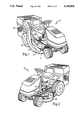
- FIG. 1 is a right-side perspective view of the riding mower of this invention
- FIG. 2 is a left-side perspective view of the riding mower of the present invention
- FIG. 3 is a rear-elevational view of the riding mower of the present invention, partially fragmented to show certain portions of the hydrostatic transmission control linkage, with other portions of the linkage shown in phantom;
- FIG. 4 is an exploded view of the hydrostatic control linkage of the present invention.
- FIG. 5 is a top plan view of the air-assisted grass discharge system of the present invention.
- FIG. 6 is a side schematic view of the foot-operated height adjustment mechanism of the present invention, shown in multiple settings.
- FIG. 7 is a side schematic view of the foot-operated height adjustment mechanism of the present invention, shown in its locked uppermost position.
- riding lawn mower 10 is illustrated as including air-assisted discharge system 12, hydrostatic shift linkage 14, and foot-operated pedal height adjustment mechanism 16.
- the remainder of riding mower 10 is considered to be conventional and is depicted only generally for purposes of illustrating the preferred embodiment of the present invention.
- Those skilled in the art will readily understand the relationship of the purely conventional components to system 12, linkage 14, and mechanism 16 in light of the description and drawings set forth herein.
- hydrostatic shift linkage 14 consists of handle 18 secured to the distal end of control lever 20 which extends generally vertically through slot 22 in rear fender 24.
- control lever 20 may be straight; however, the preferred configuration is angled outwardly as shown in FIGS. 3 and 4.
- slot 22 may include a plurality of transverse indentations in one side thereof for selectively engaging control lever 20, each of said indentations corresponding to a different speed setting for transmission 26. It is also contemplated that slot 22 include no such indentations so that control lever 20 may be positioned virtually anywhere along the link of slot 22, thereby providing for a number of speed control settings completely unlimited by the number of indentations.
- slot 22 includes no such indentations, but includes a single protrusion 28 which corresponds to the reverse setting of hydrostatic transmission 26.
- control rod 32 is secured in a spring-loaded manner to control lever 20 by means cf bracket 34 and torsion spring 36. Lateral portion 38 of control rod 32 is secured to frame 40 by means of clamps 42, which allow rotational movement of control rod 32 about the longitudinal axis of lateral portion 38.
- control rod 32 further includes a first downwardly extending portion 44 connecting upper curved portion 30 to lateral portion 38, and a second downwardly extending portion 46 which is pivotally secured at its distal end to link 48.
- link 48 is generally longitudinal with respect to riding mower 10, and is operatively secured to speed adjustment member 50 of transmission 26. The operation of speed adjustment member 50 and transmission 26 are purely conventional and will be well understood to those skilled in the art.
- control rod 32 has hole 52 formed therein which aligns with a similar hole (not shown) in link 48.
- bolt 54 extends through hole 52 and the adjacent hole in link 48 and is secured therein by nut 56.
- the threaded end of bolt 54 extends through slot 58 and bracket 60, with washers 62, frictional elements 64, and compression spring 66 all being fitted onto bolt 54 and retained by nut 58 as shown in FIG. 4.
- Bracket 60 is secured to lower vertical wall 68 of frame 40, preferably by means of screws 70, nuts 72, and resilient spacers 74.
- fore and aft movement of handle 18 results in corresponding fore and aft movement of downwardly extending position 46, which, in turn, produces substantially linear fore and aft movement of speed adjustment member 50.
- the movement of downwardly extending portion 46 is resisted by the abrasive action of frictional elements 64 bearinq on the opposite side portions of bracket 60 adjacent slot 58.
- the degree of such resistance may be adjusted, if desired, by loosening or tightening nut 68, thereby decreasing or increasing, respectively, the force exerted by compression spring 66.
- FIG. 5 represents a top plan view of the air-assisted discharge system 12 incorporated in the preferred embodiment of riding mower 10.
- Blower 78 is mounted atop otherwise conventional cutting deck 80 which, in the preferred embodiment shown, includes two cutting blade housings 82 and 84.
- the construction of deck 80 and housinqs 82 and 84 is purely conventional and will be readily known to those skilled in the art.
- Blower 78 is of a generally conventional design, and includes an intake area 86 and a high velocity output nozzle 88.
- Conduit 90 routes the air provided by blower: 78 to an area of duct 92 generally adjacent and slightly upstream of conventional discharge chute 94 which, as those skilled in the art will fully understand, directs grass and other clippings through duct 92 into collection container 96 for storage and subsequent disposal.
- blower 78 is driven by means of pulley 98 extending from the engine (not shown) which engages belt 100.
- Pulley 98 and belt 100 are typically employed on prior art devices to drive the cutting blades, so that blower 78 and its accompanying conduit work 90 may be retro-fitted relatively easily to conventional mowers.
- pulley 78 When configured as shown, pulley 78 operates to draw air inwardly through intake area 86 and force the air at a relatively high velocity through conduit 90 into duct 94 at area 102 slightly upstream of discharge chute 92.
- blower 78 will readily understand that the burst of high velocity air provided by blower 78 will prevent the clogging of grass, particularly when cut wet, which frequently occurs at or near area 102 of duct 92.
- mechanism 16 includes a pedal 104 which consists essentially of a rubberized face portion 106 secured to a rigid support member 108 which extends through slot 110 in foot rest 112 (see FIG. 2).
- the lower portion 114 of support member 108 is pivotally secured to the underside of foot rest 112, preferably by means of bracket 116, studs 118, and nuts 120.
- link 124 comprise a solid rod having curved first and second end portions, the first and second end portions being inserted and suitably retained within holes in plates 122 and 126, respectively.
- Height adjustment plate 126 is slidably disposed on transverse tube 128, which is pivotally secured to the underside of frame 40 by conventional means known to those skilled in the art.
- Connecting member 130 is rigidly secured to tube 128 (by welding, for example) and is adjustably attached to plate 126 by means of screws 132 extending through slots 134 and 136, and nuts 138.
- This preferred configuration provides for an additional degree of adjustment for height adjustment mechanism 16, wherein nuts 138 may be loosened temporarily and plate 126 rotated slightly about tube 128, thereby changing the relative position between plate 128 and connecting member 130.
- support arms 140 which are pivotally secured to members 142 which extend from generally opposite transverse sides of cutting deck 80.
- members 142 which extend from generally opposite transverse sides of cutting deck 80.
- Height adjustment plate 126 includes a generally vertical slot 144 which is adapted to engage the lower end 146 of generally vertical link 148.
- the upper end 150 of link 148 is selectively positionable among one of several indentations 152 formed in support plate 154.
- the upper edge of slot 144 bears downwardly on lower end 146 of link 148, thereby forcibly maintaining upper end 150 in its selected indentation.
- the tension is removed from link 148, thereby necessitating the use of the spring 156 to maintain upper end 150 in its preselected position.
- height adjustment mechanism 16 is capable of maintaining cutting deck 80 at five different cutting levels, one cutting level corresponding to each of the five indentations 152. Those skilled in the art, however, will recognize that any number of cutting height levels may be incorporated within the confines of the present invention.
- the relative positions of pedal 104, height adjustment plate 126, link 148, support arms 140, and cutting deck 80 are shown for three positions designated by the letters A, B, and C in FIG. 6. As shown, position A represents the lowest available cutting height for cutting deck 80, position B represents an intermediate cutting height, and position C represents the highest cutting height available for normal cutting.
- height adjustment mechanism 16 is shown in its locked uppermost position which can be used for cutting, but is generally intended for use when clearing large obstacles or when traversing areas which do not need to be cut.
- height adjustment mechanism 16 includes locking member 158 mounted to pedal 104 adjacent face 106.
- Spring 160 serves to maintain locking member 158 generally in the position shown in FIGS. 6 and 7.
- Depressing pedal 104 causes catch 162 to engage the forward edge of slot 164 in foot rest 112.
- the locking of pedal 104 in its forward-most position raises plate 126 sufficiently to release the tension on the lower end 146 of link 148, so that lower end 146 is free to slide within slot 144.
- the upper end 150 of link 148 may be repositioned to the indentation 152 corresponding to the desired cutting height.
- Locking member 158 is released by slightly depressing 104 to relieve the pressure from catch 162, and depressing tab 166, thereby causing locking member 158 to pivot slightly about screw 168 and disengaging catch 162 from slot 164. Upon the release of tab 158 by the user's foot, locking member 158 returns to its original position by virtue of the tension produced spring 160.
- cutting deck 80 may be raised to its uppermost position, conveniently locked into place, and easily released back to its original cutting height with minimum fuss and attention by the user.
- link 148 be constructed from a single solid rod, with ends 146 and 150 being bent at generally right angles to the central body portion.
- the lower end 146 may be conventionally retained within slot 144, and the upper end 150 conventionally retained within the opening in support plate 154, with a rubber knob disposed on end 150 for the comfort and convenience of the user.
Abstract
Description
Claims (35)
Priority Applications (1)
| Application Number | Priority Date | Filing Date | Title |
|---|---|---|---|
| US07/625,553 US5138825A (en) | 1990-12-11 | 1990-12-11 | Riding mower having a pedal operated height adjustment mechanism, air assisted discharge, and improved hydrostatic shift linkage |
Applications Claiming Priority (1)
| Application Number | Priority Date | Filing Date | Title |
|---|---|---|---|
| US07/625,553 US5138825A (en) | 1990-12-11 | 1990-12-11 | Riding mower having a pedal operated height adjustment mechanism, air assisted discharge, and improved hydrostatic shift linkage |
Publications (1)
| Publication Number | Publication Date |
|---|---|
| US5138825A true US5138825A (en) | 1992-08-18 |
Family
ID=24506621
Family Applications (1)
| Application Number | Title | Priority Date | Filing Date |
|---|---|---|---|
| US07/625,553 Expired - Lifetime US5138825A (en) | 1990-12-11 | 1990-12-11 | Riding mower having a pedal operated height adjustment mechanism, air assisted discharge, and improved hydrostatic shift linkage |
Country Status (1)
| Country | Link |
|---|---|
| US (1) | US5138825A (en) |
Cited By (39)
| Publication number | Priority date | Publication date | Assignee | Title |
|---|---|---|---|---|
| US5323594A (en) * | 1992-12-21 | 1994-06-28 | Board Of Regents For The Oklahoma Agricultural & Mechanical College Acting For & On Behalf Of Oklahoma State University | Grain harvester |
| US5337543A (en) * | 1991-10-04 | 1994-08-16 | Kubota Corporation | Lawn mower for use both as riding and walking operator type |
| US5351467A (en) * | 1993-07-26 | 1994-10-04 | Noma Outdoor Products, Inc. | Height adjustment mechanism for riding mower cutting deck |
| US5388394A (en) * | 1993-05-25 | 1995-02-14 | Murray Outdoor Products, Inc. | Lawn mower grass collection indicator |
| WO1998009496A1 (en) * | 1996-09-05 | 1998-03-12 | Al Borling | Rear suspension for riding mower |
| DE19737181A1 (en) * | 1997-08-26 | 1999-03-11 | Kober Ag | Lawn tractor |
| US5911672A (en) * | 1997-07-25 | 1999-06-15 | Mtd Products Inc. | Vacuum actuated control mechanism |
| US5950408A (en) * | 1997-07-25 | 1999-09-14 | Mtd Products Inc | Bag-full indicator mechanism |
| US6082477A (en) * | 1993-09-30 | 2000-07-04 | Kubota Corporation | Engine hood |
| US6427430B1 (en) | 2000-08-15 | 2002-08-06 | Deere & Company | Pedal lift system for lawn tractor mower deck |
| US6494028B2 (en) | 2000-07-20 | 2002-12-17 | White Consolidated Industries, Inc. | Deck lift apparatus for riding mower |
| US6588188B2 (en) | 2001-01-05 | 2003-07-08 | Bush Hog, L.L.C. | Foot lift cutter deck mower units |
| US20040053742A1 (en) * | 2002-07-11 | 2004-03-18 | Axel Schaedler | Vacuum actuated direction and speed control mechanism |
| US20040104064A1 (en) * | 1998-10-08 | 2004-06-03 | Masaru Iida | Axle driving apparatus |
| US6748729B1 (en) | 2003-02-26 | 2004-06-15 | Wayne Dennis Johns | Mower cut control apparatus and method |
| US6837032B1 (en) | 2000-08-15 | 2005-01-04 | Deere & Company | Pedal actuated height adjustment mechanism for a mower cutting deck |
| US7003937B1 (en) | 2004-04-22 | 2006-02-28 | Tommy Tarver | Mower deck height adjustment device |
| US7013626B1 (en) | 2003-07-18 | 2006-03-21 | Auburn Consolidated Industries, Inc. | Walk behind mower |
| US20070012016A1 (en) * | 2005-07-13 | 2007-01-18 | Auburn Consolidated Industries, Inc. | Mower deck height adjustment |
| EP1774845A1 (en) * | 2005-10-13 | 2007-04-18 | Deere & Company | Rear discharge mower deck |
| US20070271895A1 (en) * | 2006-05-26 | 2007-11-29 | Kubota Corporation | Apparatus for vertically moving mower unit for riding mower |
| US20080190087A1 (en) * | 2007-02-14 | 2008-08-14 | Elhardt Paul M | Mower Deck Lift System With Transport Lock |
| US20080229725A1 (en) * | 2007-03-20 | 2008-09-25 | Mtd Products Inc | Foot actuated height adjustment mechanism for a lawnmower cutting deck |
| US7540134B1 (en) | 2003-07-17 | 2009-06-02 | Pat Reich | Riding mower with deck height adjustment |
| WO2010033892A1 (en) * | 2008-09-22 | 2010-03-25 | Martin Engineering Company | Conveyor belt training idler with a locking mechanism |
| US20140250851A1 (en) * | 2011-09-21 | 2014-09-11 | Husqvarna Ab | Lawn care vehicle with cutting deck lifting pedal |
| US20140260162A1 (en) * | 2008-01-20 | 2014-09-18 | James W. Lancaster | Height of cut adjustment system for mower cutting deck |
| US20150121832A1 (en) * | 2013-11-01 | 2015-05-07 | Amerequip Corporation | Adjustment mechanism for lawn mower deck attached to a tractor |
| JP2016116528A (en) * | 2016-02-26 | 2016-06-30 | 井関農機株式会社 | Grass mower |
| US20160212934A1 (en) * | 2015-01-28 | 2016-07-28 | Briggs & Stratton Corporation | Mower utility bed |
| DE102016207400A1 (en) | 2015-05-01 | 2016-11-03 | Deere & Company | CUTTING HEIGHT CONTROL SYSTEM |
| US9642304B1 (en) | 2014-06-05 | 2017-05-09 | Totally New Technologies LLC | Floating deck system for riding lawn mowers |
| US9861035B2 (en) | 2015-05-01 | 2018-01-09 | Deere & Company | Height of cut control system |
| CN108243730A (en) * | 2018-03-22 | 2018-07-06 | 苏州金莱克精密机械有限公司 | A kind of height adjustment mechanism and lawn care apparatus |
| US20190327895A1 (en) * | 2018-04-26 | 2019-10-31 | Kubota Corporation | Grass mower |
| US20200120866A1 (en) * | 2018-10-17 | 2020-04-23 | Mean Green Products, LLC | Deck height control system |
| AU2018288056B2 (en) * | 2017-06-23 | 2020-07-02 | Husqvarna Ab | Deck lift assembly for a riding lawn care vehicle |
| CN111802063A (en) * | 2020-07-22 | 2020-10-23 | 江先庆 | Municipal garden collecting device that mows |
| US11178814B2 (en) * | 2017-03-01 | 2021-11-23 | Hurricane, Inc. | Vehicle with debris blower and lawn mower |
Citations (19)
| Publication number | Priority date | Publication date | Assignee | Title |
|---|---|---|---|---|
| US1614386A (en) * | 1924-11-12 | 1927-01-11 | Peebles | Lawn mower |
| US1899564A (en) * | 1928-12-24 | 1933-02-28 | Charles A Frey | Lawn mower |
| US2076056A (en) * | 1934-11-28 | 1937-04-06 | Albert F Woodford | Power mower |
| US2491544A (en) * | 1946-06-14 | 1949-12-20 | Albert A Arkenberg | Lawn mower |
| US2848859A (en) * | 1957-04-03 | 1958-08-26 | Huffman Mfg Company | Lawn mower with adjustable wheel mounting assembly |
| US2945338A (en) * | 1958-03-24 | 1960-07-19 | Porter Cable Machine Co | Rotary cutter type lawn mower |
| US3091906A (en) * | 1962-04-30 | 1963-06-04 | Russell V Hall | Power lawn mower |
| US3430421A (en) * | 1967-01-03 | 1969-03-04 | Theodore L Matthews | Combined mower and vacuum device |
| US3483682A (en) * | 1966-08-18 | 1969-12-16 | Root Mfg Co Inc | Cutter suspension unit for riding mowers |
| US3742685A (en) * | 1971-12-29 | 1973-07-03 | Stellar Ind Inc | Lawn mower with hydrostatic drive |
| US3984893A (en) * | 1975-04-22 | 1976-10-12 | Ashley Marion L | Vacuum sweeper device |
| US4120136A (en) * | 1976-12-27 | 1978-10-17 | Massey-Ferguson Inc. | Implement supporting and lifting linkage |
| US4316356A (en) * | 1980-07-28 | 1982-02-23 | Planeta Eugene J | Lawn mower for cutting on an inclined surface |
| US4395865A (en) * | 1981-01-28 | 1983-08-02 | Davis Jr Robert D | Self propelled lawn mower |
| US4433532A (en) * | 1982-07-29 | 1984-02-28 | Deere & Company | Lawn mower bagging system including air assist |
| US4597251A (en) * | 1985-05-02 | 1986-07-01 | Cornellier Maurice H | Lawnmower |
| US4773205A (en) * | 1986-08-01 | 1988-09-27 | Outboard Marine Corporation | Anti-clogging means for bulk material flow duct |
| US4920734A (en) * | 1987-06-17 | 1990-05-01 | Ferris Industries, Inc. | Drive control for walk-behind mower with hydrostatic transmission |
| US4934130A (en) * | 1985-09-27 | 1990-06-19 | Husqvarna Aktiebolag | Mower |
-
1990
- 1990-12-11 US US07/625,553 patent/US5138825A/en not_active Expired - Lifetime
Patent Citations (19)
| Publication number | Priority date | Publication date | Assignee | Title |
|---|---|---|---|---|
| US1614386A (en) * | 1924-11-12 | 1927-01-11 | Peebles | Lawn mower |
| US1899564A (en) * | 1928-12-24 | 1933-02-28 | Charles A Frey | Lawn mower |
| US2076056A (en) * | 1934-11-28 | 1937-04-06 | Albert F Woodford | Power mower |
| US2491544A (en) * | 1946-06-14 | 1949-12-20 | Albert A Arkenberg | Lawn mower |
| US2848859A (en) * | 1957-04-03 | 1958-08-26 | Huffman Mfg Company | Lawn mower with adjustable wheel mounting assembly |
| US2945338A (en) * | 1958-03-24 | 1960-07-19 | Porter Cable Machine Co | Rotary cutter type lawn mower |
| US3091906A (en) * | 1962-04-30 | 1963-06-04 | Russell V Hall | Power lawn mower |
| US3483682A (en) * | 1966-08-18 | 1969-12-16 | Root Mfg Co Inc | Cutter suspension unit for riding mowers |
| US3430421A (en) * | 1967-01-03 | 1969-03-04 | Theodore L Matthews | Combined mower and vacuum device |
| US3742685A (en) * | 1971-12-29 | 1973-07-03 | Stellar Ind Inc | Lawn mower with hydrostatic drive |
| US3984893A (en) * | 1975-04-22 | 1976-10-12 | Ashley Marion L | Vacuum sweeper device |
| US4120136A (en) * | 1976-12-27 | 1978-10-17 | Massey-Ferguson Inc. | Implement supporting and lifting linkage |
| US4316356A (en) * | 1980-07-28 | 1982-02-23 | Planeta Eugene J | Lawn mower for cutting on an inclined surface |
| US4395865A (en) * | 1981-01-28 | 1983-08-02 | Davis Jr Robert D | Self propelled lawn mower |
| US4433532A (en) * | 1982-07-29 | 1984-02-28 | Deere & Company | Lawn mower bagging system including air assist |
| US4597251A (en) * | 1985-05-02 | 1986-07-01 | Cornellier Maurice H | Lawnmower |
| US4934130A (en) * | 1985-09-27 | 1990-06-19 | Husqvarna Aktiebolag | Mower |
| US4773205A (en) * | 1986-08-01 | 1988-09-27 | Outboard Marine Corporation | Anti-clogging means for bulk material flow duct |
| US4920734A (en) * | 1987-06-17 | 1990-05-01 | Ferris Industries, Inc. | Drive control for walk-behind mower with hydrostatic transmission |
Cited By (61)
| Publication number | Priority date | Publication date | Assignee | Title |
|---|---|---|---|---|
| US5337543A (en) * | 1991-10-04 | 1994-08-16 | Kubota Corporation | Lawn mower for use both as riding and walking operator type |
| US5323594A (en) * | 1992-12-21 | 1994-06-28 | Board Of Regents For The Oklahoma Agricultural & Mechanical College Acting For & On Behalf Of Oklahoma State University | Grain harvester |
| US5388394A (en) * | 1993-05-25 | 1995-02-14 | Murray Outdoor Products, Inc. | Lawn mower grass collection indicator |
| US5351467A (en) * | 1993-07-26 | 1994-10-04 | Noma Outdoor Products, Inc. | Height adjustment mechanism for riding mower cutting deck |
| US6082477A (en) * | 1993-09-30 | 2000-07-04 | Kubota Corporation | Engine hood |
| WO1998009496A1 (en) * | 1996-09-05 | 1998-03-12 | Al Borling | Rear suspension for riding mower |
| US5799475A (en) * | 1996-09-05 | 1998-09-01 | Mtd Products Inc | Rear suspension for riding mower |
| US5911672A (en) * | 1997-07-25 | 1999-06-15 | Mtd Products Inc. | Vacuum actuated control mechanism |
| US6230608B1 (en) | 1997-07-25 | 2001-05-15 | Mtd Products Inc | Vacuum actuated control mechanism |
| US5950408A (en) * | 1997-07-25 | 1999-09-14 | Mtd Products Inc | Bag-full indicator mechanism |
| DE19737181C2 (en) * | 1997-08-26 | 1999-07-22 | Kober Ag | Lawn tractor |
| DE19737181A1 (en) * | 1997-08-26 | 1999-03-11 | Kober Ag | Lawn tractor |
| US7011182B2 (en) * | 1998-10-08 | 2006-03-14 | Masaru Iida | Axle driving apparatus |
| US20040104064A1 (en) * | 1998-10-08 | 2004-06-03 | Masaru Iida | Axle driving apparatus |
| US6494028B2 (en) | 2000-07-20 | 2002-12-17 | White Consolidated Industries, Inc. | Deck lift apparatus for riding mower |
| US6837032B1 (en) | 2000-08-15 | 2005-01-04 | Deere & Company | Pedal actuated height adjustment mechanism for a mower cutting deck |
| US6427430B1 (en) | 2000-08-15 | 2002-08-06 | Deere & Company | Pedal lift system for lawn tractor mower deck |
| US6588188B2 (en) | 2001-01-05 | 2003-07-08 | Bush Hog, L.L.C. | Foot lift cutter deck mower units |
| US20040053742A1 (en) * | 2002-07-11 | 2004-03-18 | Axel Schaedler | Vacuum actuated direction and speed control mechanism |
| US7044260B2 (en) | 2002-07-11 | 2006-05-16 | Mtd Products Inc. | Vacuum actuated direction and speed control mechanism |
| US6748729B1 (en) | 2003-02-26 | 2004-06-15 | Wayne Dennis Johns | Mower cut control apparatus and method |
| US7540134B1 (en) | 2003-07-17 | 2009-06-02 | Pat Reich | Riding mower with deck height adjustment |
| US7013626B1 (en) | 2003-07-18 | 2006-03-21 | Auburn Consolidated Industries, Inc. | Walk behind mower |
| US7003937B1 (en) | 2004-04-22 | 2006-02-28 | Tommy Tarver | Mower deck height adjustment device |
| US20060096267A1 (en) * | 2004-04-22 | 2006-05-11 | Tommy Tarver | Mower deck height adjustment device |
| US20070012016A1 (en) * | 2005-07-13 | 2007-01-18 | Auburn Consolidated Industries, Inc. | Mower deck height adjustment |
| US7540135B2 (en) | 2005-07-13 | 2009-06-02 | Claude Strope | Mower deck height adjustment |
| EP1774845A1 (en) * | 2005-10-13 | 2007-04-18 | Deere & Company | Rear discharge mower deck |
| US20070271895A1 (en) * | 2006-05-26 | 2007-11-29 | Kubota Corporation | Apparatus for vertically moving mower unit for riding mower |
| US7434379B2 (en) * | 2006-05-26 | 2008-10-14 | Kubota Corporation | Apparatus for vertically moving mower unit for riding mower |
| US7448191B2 (en) | 2007-02-14 | 2008-11-11 | Deere & Company | Mower deck lift system with transport lock |
| US20090031687A1 (en) * | 2007-02-14 | 2009-02-05 | Elhardt Paul M | Mower deck lift system with transport lock |
| EP1958492A1 (en) | 2007-02-14 | 2008-08-20 | Deere & Company | Mower deck lift system |
| US20080190087A1 (en) * | 2007-02-14 | 2008-08-14 | Elhardt Paul M | Mower Deck Lift System With Transport Lock |
| US7614207B2 (en) | 2007-02-14 | 2009-11-10 | Deere & Company | Mower deck lift system with transport lock |
| US7578117B2 (en) | 2007-03-20 | 2009-08-25 | Mtd Products Inc | Foot actuated height adjustment mechanism for a lawnmower cutting deck |
| US20080229725A1 (en) * | 2007-03-20 | 2008-09-25 | Mtd Products Inc | Foot actuated height adjustment mechanism for a lawnmower cutting deck |
| US20140260162A1 (en) * | 2008-01-20 | 2014-09-18 | James W. Lancaster | Height of cut adjustment system for mower cutting deck |
| US8919087B2 (en) * | 2008-01-20 | 2014-12-30 | Exmark Mfg. Co., Inc. | Height of cut adjustment system for mower cutting deck |
| WO2010033892A1 (en) * | 2008-09-22 | 2010-03-25 | Martin Engineering Company | Conveyor belt training idler with a locking mechanism |
| US7967129B2 (en) | 2008-09-22 | 2011-06-28 | Martin Engineering Company | Conveyor belt training idler with a locking mechanism |
| US20100072032A1 (en) * | 2008-09-22 | 2010-03-25 | Martin Engineering Company | Conveyor Belt Training Idler with a Locking Mechanism |
| US20140250851A1 (en) * | 2011-09-21 | 2014-09-11 | Husqvarna Ab | Lawn care vehicle with cutting deck lifting pedal |
| US9357700B2 (en) * | 2011-09-21 | 2016-06-07 | Husqvarna Ab | Lawn care vehicle with cutting deck lifting pedal |
| US20150121832A1 (en) * | 2013-11-01 | 2015-05-07 | Amerequip Corporation | Adjustment mechanism for lawn mower deck attached to a tractor |
| US9642304B1 (en) | 2014-06-05 | 2017-05-09 | Totally New Technologies LLC | Floating deck system for riding lawn mowers |
| US10238036B2 (en) * | 2015-01-28 | 2019-03-26 | Briggs & Stratton Corporation | Mower utility bed |
| US20160212934A1 (en) * | 2015-01-28 | 2016-07-28 | Briggs & Stratton Corporation | Mower utility bed |
| US9693504B2 (en) * | 2015-01-28 | 2017-07-04 | Briggs & Stratton Corporation | Mower utility bed |
| US9861035B2 (en) | 2015-05-01 | 2018-01-09 | Deere & Company | Height of cut control system |
| DE102016207400A1 (en) | 2015-05-01 | 2016-11-03 | Deere & Company | CUTTING HEIGHT CONTROL SYSTEM |
| JP2016116528A (en) * | 2016-02-26 | 2016-06-30 | 井関農機株式会社 | Grass mower |
| US11178814B2 (en) * | 2017-03-01 | 2021-11-23 | Hurricane, Inc. | Vehicle with debris blower and lawn mower |
| US11019763B2 (en) | 2017-06-23 | 2021-06-01 | Husqvarna Ab | Deck lift assembly for a riding lawn care vehicle |
| AU2018288056B2 (en) * | 2017-06-23 | 2020-07-02 | Husqvarna Ab | Deck lift assembly for a riding lawn care vehicle |
| CN108243730A (en) * | 2018-03-22 | 2018-07-06 | 苏州金莱克精密机械有限公司 | A kind of height adjustment mechanism and lawn care apparatus |
| US20190327895A1 (en) * | 2018-04-26 | 2019-10-31 | Kubota Corporation | Grass mower |
| US10905047B2 (en) * | 2018-04-26 | 2021-02-02 | Kubota Corporation | Grass mower and flow booster |
| US20200120866A1 (en) * | 2018-10-17 | 2020-04-23 | Mean Green Products, LLC | Deck height control system |
| US11690318B2 (en) * | 2018-10-17 | 2023-07-04 | Generac Power Systems, Inc. | Deck height control system |
| CN111802063A (en) * | 2020-07-22 | 2020-10-23 | 江先庆 | Municipal garden collecting device that mows |
Similar Documents
| Publication | Publication Date | Title |
|---|---|---|
| US5138825A (en) | Riding mower having a pedal operated height adjustment mechanism, air assisted discharge, and improved hydrostatic shift linkage | |
| US6560952B2 (en) | Power mower with stand-on and sit-down modes | |
| US5381648A (en) | Mower deck height adjustment mechanism | |
| US11102929B2 (en) | Integrated transaxle standing mower operator platform | |
| US7578117B2 (en) | Foot actuated height adjustment mechanism for a lawnmower cutting deck | |
| US6082083A (en) | Ground speed control system | |
| US5915487A (en) | Walk-behind traction vehicle having variable speed friction drive transmission | |
| US5509496A (en) | Lawn and garden tractor hydrostatic foot control system | |
| US6658831B2 (en) | Power lawn mower with deck lift system | |
| US5564721A (en) | Coupling mechanism for a sulky | |
| US7478689B1 (en) | Vehicle steering and speed control | |
| US7607283B2 (en) | Lawn mower with deck lift system and/or pump lock-out system | |
| US5809755A (en) | Power mower with riding platform for supporting standing operator | |
| US6951092B2 (en) | Operator control system for self-propelled vehicles | |
| US7647754B2 (en) | Walk behind lawn mower control system | |
| TWI333832B (en) | Lawn mower | |
| US5511367A (en) | Lawn mower having additinal improved trim featuure | |
| EP1867227A1 (en) | Dual lever steering control mechanism | |
| US5162626A (en) | Seat switch mud flap activator integrally mounted to the seat | |
| US6668529B2 (en) | Operator control system for self-propelled vehicles | |
| US4760687A (en) | Mower deck height and clutch control | |
| US6237311B1 (en) | Reverse mowing prevention device | |
| US4934130A (en) | Mower | |
| US11240957B2 (en) | Mower deck transport lock | |
| US20210227745A1 (en) | Grounds maintenance vehicle with adjustable implement angle |
Legal Events
| Date | Code | Title | Description |
|---|---|---|---|
| AS | Assignment |
Owner name: NOMA OUTDOOR PRODUCTS, INC., A CORP. OF TN, TENNES Free format text: ASSIGNMENT OF ASSIGNORS INTEREST.;ASSIGNORS:TREFZ, HARLIN J.;GERGATT, DANIEL T.;MOSLEY, KEITH A.;AND OTHERS;REEL/FRAME:005606/0598 Effective date: 19910122 |
|
| STCF | Information on status: patent grant |
Free format text: PATENTED CASE |
|
| FEPP | Fee payment procedure |
Free format text: PAYOR NUMBER ASSIGNED (ORIGINAL EVENT CODE: ASPN); ENTITY STATUS OF PATENT OWNER: LARGE ENTITY |
|
| FPAY | Fee payment |
Year of fee payment: 4 |
|
| AS | Assignment |
Owner name: MURRAY, INC., TENNESSEE Free format text: MERGER AND CHANGE OF NAME;ASSIGNORS:NOMA INDUSTRIES;NOMA OUTDOOR PRODUCTS, INC.;WESTERN INTERNATIONAL INCORPORATED;AND OTHERS;REEL/FRAME:007666/0694 Effective date: 19870908 |
|
| FEPP | Fee payment procedure |
Free format text: PAYER NUMBER DE-ASSIGNED (ORIGINAL EVENT CODE: RMPN); ENTITY STATUS OF PATENT OWNER: LARGE ENTITY Free format text: PAYOR NUMBER ASSIGNED (ORIGINAL EVENT CODE: ASPN); ENTITY STATUS OF PATENT OWNER: LARGE ENTITY |
|
| FPAY | Fee payment |
Year of fee payment: 8 |
|
| AS | Assignment |
Owner name: GENERAL ELECTRIC CAPITAL CORPORATION, AS AGENT, IL Free format text: SECURITY AGREEMENT;ASSIGNOR:MURRAY, INC.;REEL/FRAME:011333/0036 Effective date: 20001005 |
|
| FPAY | Fee payment |
Year of fee payment: 12 |
|
| AS | Assignment |
Owner name: BRIGGS & STRATTON POWER PRODUCTS GROUP, LLC, WISCO Free format text: ASSIGNMENT OF ASSIGNORS INTEREST;ASSIGNOR:MURRAY, INC.;REEL/FRAME:016016/0600 Effective date: 20050211 |
|
| FEPP | Fee payment procedure |
Free format text: PAYER NUMBER DE-ASSIGNED (ORIGINAL EVENT CODE: RMPN); ENTITY STATUS OF PATENT OWNER: LARGE ENTITY Free format text: PAYOR NUMBER ASSIGNED (ORIGINAL EVENT CODE: ASPN); ENTITY STATUS OF PATENT OWNER: LARGE ENTITY |