US5395073A - STOL/VTOL free wing aircraft with articulated tail boom - Google Patents
STOL/VTOL free wing aircraft with articulated tail boom Download PDFInfo
- Publication number
- US5395073A US5395073A US08/007,130 US713093A US5395073A US 5395073 A US5395073 A US 5395073A US 713093 A US713093 A US 713093A US 5395073 A US5395073 A US 5395073A
- Authority
- US
- United States
- Prior art keywords
- fuselage
- aircraft
- wing
- tail
- tail boom
- Prior art date
- Legal status (The legal status is an assumption and is not a legal conclusion. Google has not performed a legal analysis and makes no representation as to the accuracy of the status listed.)
- Expired - Fee Related
Links
- 241000985905 Candidatus Phytoplasma solani Species 0.000 title abstract 3
- 230000007246 mechanism Effects 0.000 claims description 15
- 238000000034 method Methods 0.000 claims description 5
- RZVHIXYEVGDQDX-UHFFFAOYSA-N 9,10-anthraquinone Chemical compound C1=CC=C2C(=O)C3=CC=CC=C3C(=O)C2=C1 RZVHIXYEVGDQDX-UHFFFAOYSA-N 0.000 claims description 2
- 230000009471 action Effects 0.000 claims description 2
- 239000011295 pitch Substances 0.000 description 15
- 230000007704 transition Effects 0.000 description 11
- 230000000694 effects Effects 0.000 description 7
- 230000008901 benefit Effects 0.000 description 4
- 241000272517 Anseriformes Species 0.000 description 3
- 238000011084 recovery Methods 0.000 description 3
- 230000003247 decreasing effect Effects 0.000 description 2
- 238000012986 modification Methods 0.000 description 2
- 230000004048 modification Effects 0.000 description 2
- YXIWHUQXZSMYRE-UHFFFAOYSA-N 1,3-benzothiazole-2-thiol Chemical compound C1=CC=C2SC(S)=NC2=C1 YXIWHUQXZSMYRE-UHFFFAOYSA-N 0.000 description 1
- PEDCQBHIVMGVHV-UHFFFAOYSA-N Glycerine Chemical compound OCC(O)CO PEDCQBHIVMGVHV-UHFFFAOYSA-N 0.000 description 1
- 241000008225 Pogonichthys macrolepidotus Species 0.000 description 1
- 230000000295 complement effect Effects 0.000 description 1
- 210000003746 feather Anatomy 0.000 description 1
- 239000000446 fuel Substances 0.000 description 1
- 230000005484 gravity Effects 0.000 description 1
- 230000001939 inductive effect Effects 0.000 description 1
- 230000009467 reduction Effects 0.000 description 1
- 230000000087 stabilizing effect Effects 0.000 description 1
- 238000006467 substitution reaction Methods 0.000 description 1
Images


Classifications
-
- B—PERFORMING OPERATIONS; TRANSPORTING
- B64—AIRCRAFT; AVIATION; COSMONAUTICS
- B64C—AEROPLANES; HELICOPTERS
- B64C39/00—Aircraft not otherwise provided for
- B64C39/02—Aircraft not otherwise provided for characterised by special use
- B64C39/024—Aircraft not otherwise provided for characterised by special use of the remote controlled vehicle type, i.e. RPV
-
- B—PERFORMING OPERATIONS; TRANSPORTING
- B64—AIRCRAFT; AVIATION; COSMONAUTICS
- B64C—AEROPLANES; HELICOPTERS
- B64C29/00—Aircraft capable of landing or taking-off vertically, e.g. vertical take-off and landing [VTOL] aircraft
- B64C29/02—Aircraft capable of landing or taking-off vertically, e.g. vertical take-off and landing [VTOL] aircraft having its flight directional axis vertical when grounded
-
- B—PERFORMING OPERATIONS; TRANSPORTING
- B64—AIRCRAFT; AVIATION; COSMONAUTICS
- B64C—AEROPLANES; HELICOPTERS
- B64C29/00—Aircraft capable of landing or taking-off vertically, e.g. vertical take-off and landing [VTOL] aircraft
- B64C29/0008—Aircraft capable of landing or taking-off vertically, e.g. vertical take-off and landing [VTOL] aircraft having its flight directional axis horizontal when grounded
- B64C29/0016—Aircraft capable of landing or taking-off vertically, e.g. vertical take-off and landing [VTOL] aircraft having its flight directional axis horizontal when grounded the lift during taking-off being created by free or ducted propellers or by blowers
- B64C29/0033—Aircraft capable of landing or taking-off vertically, e.g. vertical take-off and landing [VTOL] aircraft having its flight directional axis horizontal when grounded the lift during taking-off being created by free or ducted propellers or by blowers the propellers being tiltable relative to the fuselage
-
- B—PERFORMING OPERATIONS; TRANSPORTING
- B64—AIRCRAFT; AVIATION; COSMONAUTICS
- B64C—AEROPLANES; HELICOPTERS
- B64C3/00—Wings
- B64C3/38—Adjustment of complete wings or parts thereof
- B64C3/385—Variable incidence wings
-
- B—PERFORMING OPERATIONS; TRANSPORTING
- B64—AIRCRAFT; AVIATION; COSMONAUTICS
- B64C—AEROPLANES; HELICOPTERS
- B64C39/00—Aircraft not otherwise provided for
- B64C39/04—Aircraft not otherwise provided for having multiple fuselages or tail booms
-
- B—PERFORMING OPERATIONS; TRANSPORTING
- B64—AIRCRAFT; AVIATION; COSMONAUTICS
- B64U—UNMANNED AERIAL VEHICLES [UAV]; EQUIPMENT THEREFOR
- B64U50/00—Propulsion; Power supply
- B64U50/10—Propulsion
- B64U50/11—Propulsion using internal combustion piston engines
-
- B—PERFORMING OPERATIONS; TRANSPORTING
- B64—AIRCRAFT; AVIATION; COSMONAUTICS
- B64U—UNMANNED AERIAL VEHICLES [UAV]; EQUIPMENT THEREFOR
- B64U50/00—Propulsion; Power supply
- B64U50/10—Propulsion
- B64U50/15—Propulsion using combustion exhausts other than turbojets or turbofans, e.g. using rockets, ramjets, scramjets or pulse-reactors
-
- B—PERFORMING OPERATIONS; TRANSPORTING
- B64—AIRCRAFT; AVIATION; COSMONAUTICS
- B64U—UNMANNED AERIAL VEHICLES [UAV]; EQUIPMENT THEREFOR
- B64U70/00—Launching, take-off or landing arrangements
- B64U70/30—Launching, take-off or landing arrangements for capturing UAVs in flight by ground or sea-based arresting gear, e.g. by a cable or a net
-
- B—PERFORMING OPERATIONS; TRANSPORTING
- B64—AIRCRAFT; AVIATION; COSMONAUTICS
- B64U—UNMANNED AERIAL VEHICLES [UAV]; EQUIPMENT THEREFOR
- B64U70/00—Launching, take-off or landing arrangements
- B64U70/70—Launching or landing using catapults, tracks or rails
-
- B—PERFORMING OPERATIONS; TRANSPORTING
- B64—AIRCRAFT; AVIATION; COSMONAUTICS
- B64D—EQUIPMENT FOR FITTING IN OR TO AIRCRAFT; FLIGHT SUITS; PARACHUTES; ARRANGEMENTS OR MOUNTING OF POWER PLANTS OR PROPULSION TRANSMISSIONS IN AIRCRAFT
- B64D2201/00—Airbags mounted in aircraft for any use
-
- B—PERFORMING OPERATIONS; TRANSPORTING
- B64—AIRCRAFT; AVIATION; COSMONAUTICS
- B64U—UNMANNED AERIAL VEHICLES [UAV]; EQUIPMENT THEREFOR
- B64U2201/00—UAVs characterised by their flight controls
- B64U2201/20—Remote controls
-
- B—PERFORMING OPERATIONS; TRANSPORTING
- B64—AIRCRAFT; AVIATION; COSMONAUTICS
- B64U—UNMANNED AERIAL VEHICLES [UAV]; EQUIPMENT THEREFOR
- B64U30/00—Means for producing lift; Empennages; Arrangements thereof
- B64U30/10—Wings
-
- B—PERFORMING OPERATIONS; TRANSPORTING
- B64—AIRCRAFT; AVIATION; COSMONAUTICS
- B64U—UNMANNED AERIAL VEHICLES [UAV]; EQUIPMENT THEREFOR
- B64U50/00—Propulsion; Power supply
- B64U50/10—Propulsion
- B64U50/13—Propulsion using external fans or propellers
-
- B—PERFORMING OPERATIONS; TRANSPORTING
- B64—AIRCRAFT; AVIATION; COSMONAUTICS
- B64U—UNMANNED AERIAL VEHICLES [UAV]; EQUIPMENT THEREFOR
- B64U70/00—Launching, take-off or landing arrangements
- B64U70/60—Take-off or landing of UAVs from a runway using their own power
-
- B—PERFORMING OPERATIONS; TRANSPORTING
- B64—AIRCRAFT; AVIATION; COSMONAUTICS
- B64U—UNMANNED AERIAL VEHICLES [UAV]; EQUIPMENT THEREFOR
- B64U70/00—Launching, take-off or landing arrangements
- B64U70/80—Vertical take-off or landing, e.g. using rockets
-
- Y—GENERAL TAGGING OF NEW TECHNOLOGICAL DEVELOPMENTS; GENERAL TAGGING OF CROSS-SECTIONAL TECHNOLOGIES SPANNING OVER SEVERAL SECTIONS OF THE IPC; TECHNICAL SUBJECTS COVERED BY FORMER USPC CROSS-REFERENCE ART COLLECTIONS [XRACs] AND DIGESTS
- Y10—TECHNICAL SUBJECTS COVERED BY FORMER USPC
- Y10S—TECHNICAL SUBJECTS COVERED BY FORMER USPC CROSS-REFERENCE ART COLLECTIONS [XRACs] AND DIGESTS
- Y10S446/00—Amusement devices: toys
- Y10S446/901—Detachably adhesive
Definitions
- the present invention relates generally to short field and vertical take-off and landing (STOL/VSTOL) aircraft and, more particularly, to a STOL/VTOL aircraft having a fuselage with a tail rudder section which is articulated, relative to the fuselage, for movement out of the thrust line of a propulsion system for use in transitioning between STOL and straight and level flight.
- STOL/VSTOL short field and vertical take-off and landing
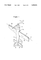
- a STOL/VTOL free wing aircraft 10 of the invention disclosed in the aforementioned co-pending application which comprises a fuselage 12, a tail section 14 and a free wing 16 with a propulsion system including an engine 18 at the forward end of the fuselage for driving a propeller 20.
- a free wing or "freewing” is a wing attached to an aircraft fuselage in a manner such that the wing is freely pivotable about its spanwise axis forward of its aerodynamic center. This arrangement enables the wing to have an angle of attack which is determined solely by aerodynamic forces acting on the wing.
- Rotation of the wing without pilot intervention, induced by changes in the direction of relative wind over the wing surfaces, causes the angle of incidence between the wing and the aircraft fuselage to vary so that the wing presents a substantially constant angle of attack to the relative wind which, in horizontal flight, enables the aircraft to be essentially stall free.
- the free wing 16 is free to rotate or pivot about its spanwise axis 22 forward of its aerodynamic center.
- Free wing 16 includes left and right wings 16a and 16b extending from opposite sides of fuselage 12; these wings are coupled together to collectively freely pivot about axis 22.
- the left and right wings 16a,16b may be adjustable in pitch relative to one another as disclosed in the aforesaid application, the relevant disclosure of which is incorporated by reference herein.
- Aircraft 10 further includes rudders 24 and elevators 26 in tail section 14 which may be controlled in a conventional manner for yaw and pitch control, respectively. Further, while a single propeller for the propulsion system is illustrated at 20 in FIG.
- propulsion system means the same propulsion system for supplying the necessary thrust for both horizontal and vertical flight operations and is not necessarily limited to a single thrust producing system, such as a single propeller, but could include multiple thrust producing systems such as a pair of engines driving separate propellers, provided that the multiple thrust producing systems are used for supplying thrust in both vertical and horizontal flight modes.
- the operation of the VTOL free wing aircraft 10 is as follows. At launch, the aircraft 10 is mounted in a vertical orientation such as depicted in FIG. 1, on a rail system schematically depicted at 60. Rail system 60 may comprise simply a guide or a track with complementary guide or track following members on the aircraft 10 for guiding the aircraft from vertical movement for a limited initial predetermined distance at lift-off. With the engine started and propeller backwash providing an air flow over the wings 16a,16b, aircraft 10 lifts off of launch rail 60. Catapult assists may be provided. Yaw and pitch controls are maintained by rudder 24 and elevator 26, respectively. Roll control is achieved by differential setting of the pitch of the free wings 16a,16b under pilot or computer control or remote control from a remote controller station (not shown).
- the air flow over wings 16a,16b provides dynamic forces on the wings to control the roll of the aircraft 10 during launch.
- the wings 16a,16b at launch are freely rotatable and the dynamic pressure on all control surfaces as a result of backwash from the propulsion system is intended to allow roll, pitch and yaw control over the aircraft 10 during the initial phases of vertical launch.
- the pilot, computer or remote controller gives a down elevator signal, causing the fuselage to pitch toward a horizontal orientation.
- the thrust vector also inclines from the vertical and thus has a horizontal thrust component.
- the horizontal speed of the aircraft increases, causing the freely rotatable wing 16 to rotate relative to the fuselage in accordance with the relative wind.
- the effects of the relative wind acting on the freely rotating wing 16a,16b quickly overcome the effects of the airflow over the wings from the propulsion system and, with increasing horizontal speed, the wing develops lift.
- the aircraft 10 soon transitions into horizontal flight in a free wing flight mode.
- pitch, yaw and roll control are provided by the elevators, rudders and differentially pivoted wings 16a and 16b.
- Ailerons may be provided on wing 16 if desired.
- the wing could be locked to the fuselage before rotating the fuselage up.
- the aircraft may be positioned in the vertical orientation.
- a further alternative to reduce horizontal speed while transitioning from horizontal to vertical flight is to provide wing devices such as spoilers or elevators at the trailing edge of the wing.
- a canard could be located in the nose of the fuselage to provide leverage to the fuselage to transition to the vertical.
- a canard could be recessed within the nose of the aircraft and displaced outwardly of the aircraft at the time of the transition to leverage the fuselage upwardly.
- the canard of course, in any event could be a free wing or fixed.
- the pitch, roll and yaw commands again control the position of the aircraft to a location directly over a net 66.
- the engine is turned off and the aircraft drops into the net.
- tail section Since the tail section is fixed to the fuselage and thereby immovable relative to the longitudinal axis and the thrust axis of the fuselage, relatively sophisticated launch (take-off) and recovery (landing) systems are necessary, such as the launch rail system 60 mentioned above for take-off, and netted recovery systems to land the VTOL aircraft 10 such as depicted in FIG. 6 of the prior application, said drawing figure and related written description being incorporated by reference herein in its entirety.
- extremely long and complex landing gear extending downwardly below the tail section 14 in the vertical flight mode of FIG. 1 would be necessary for STOL and VTOL operations.
- This type of landing gear e.g., a so-called moon rocket landing gear
- STOL/VTOL vertical and short take-off and landing capabilities
- Another object is to provide a STOL/VTOL free wing aircraft having a thrust line movable between vertical and horizontal orientations without affecting the relative horizontal positioning of at least flight control surfaces located in the tail section to enable use of relatively non-complex and short landing gear.
- a free wing aircraft comprises a fuselage including a source of propulsion for propelling the aircraft in horizontal flight and in a short field take-off and landing (STOL) flight mode.
- a free wing is connected to the fuselage for free pivotal movement relative to the fuselage about a spanwise axis extending forwardly of the aerodynamic center of the wing.
- a tail boom is connected to the fuselage.
- the tail boom is formed with horizontal tail surfaces and vertical tail surfaces to provide for directional stability and yaw control.
- a mechanism is provided for relatively rotating the fuselage relative to the tail boom about an axis of rotation extending parallel to or coincident with the spanwise axis.
- the relatively rotating mechanism is operable to position the thrust line of the fuselage into an angle approaching, or of, 90° relative to a longitudinal axis of the tail boom to enable the thrust of the propulsion system to propel the aircraft in the STOL flight mode.
- forward portions of the boom are connected to the fuselage and the tail surfaces are located at the rearwardly extending portions of the boom.
- the tail surfaces are positioned out of the propulsion slip stream in STOL flight mode and provide for directional stability and yaw control as a result of relative wind induced dynamic pressure acting on the tail surfaces under low horizontal flight component speeds.
- the tail surfaces may be immovable relative to the tail boom.
- the aircraft may further comprise landing wheels connected to the fuselage to project therebelow in the tilted up or STOL orientation of the fuselage relative to the tail boom.
- the aircraft further comprises left and right fixed wing center or root sections fixedly attached to the fuselage.
- the free wing preferably includes left and right free wing members respectively extending from the left and right fixed wing center sections and which are freely rotatable relative thereto.
- means is provided for selectively controllably rotating at least one of the left and right free wings relative to the other of said wings for roll control without impeding the pivotal movement thereof.
- a free wing support tube means extends transversely through the fuselage and fixed wing sections along the spanwise axis and into the left and right free wings to define a support system therefor on the fuselage.
- the free wing support tube means may be a single tube supported in the fuselage and/or the fixed wing sections on bearings to allow for free pivotal movement of the free wings as a result of rotation of the tube about its longitudinal axis caused by relative wind acting on the free wing surfaces.
- a pair of tubes may respectively extend from the left and right free wings into the left and right fixed wing center sections and the fuselage for connection to a means for selectively controllably rotating at least one of the left and right free wings relative to the other of said wings for roll control without impeding the free pivotal movement thereof.
- the tail boom preferably includes a cross tube extending transversely through the fuselage and fixed wing center sections.
- the tail boom cross tube is rotatable about its longitudinal axis via bearings mounted within the fuselage or fixed wing center sections.
- a pair of tail boom members respectively attached to opposite ends of the cross tube project rearwardly therefrom, and the tail surfaces are formed at distal ends of these boom members.
- the tail boom cross tube extends transversely through a rear portion of the fuselage in rearwardly spaced relation to the free wing axis of rotation. Portions of the tail boom members also extend forwardly from the tail boom cross tube, and two pairs of landing wheels are respectively mounted to the tail boom members in tandem spaced relationship. At least the front pair of landing wheels are mounted to the forwardly extending portions to define a stable platform on the ground which enables the aircraft to resist yawing or directional instability under cross wind conditions.
- a method of controlling an aircraft in horizontal and generally vertical flight modes comprises the steps of selectively positioning the longitudinal axis of the fuselage and the thrust line in a generally vertical direction while the longitudinal axis of the tail surfaces extends generally horizontally, out of the path of movement of the fuselage, to enable STOL or VTOL flight.
- the fuselage longitudinal axis is rotated to be coincident with the longitudinal axis of the tail surfaces, the aircraft is capable of normal straight and level flight at conventional horizontal air speeds.
- FIG. 1 is a perspective view of the VIOL free wing aircraft disclosed in the prior application, depicted in a vertical flight orientation;
- FIG. 2 is a top plan view of an aircraft according to one embodiment of the present invention in a straight and level mode of flight;
- FIG. 3 is a side elevational view of the aircraft of FIG. 2 in the straight and level flight mode
- FIG. 4 is a perspective view of the aircraft in the straight and level flight modes of FIGS. 2 and 3;
- FIG. 5 is a front elevational view of the aircraft of FIGS. 2-4;
- FIG. 6 is a top plan view of the aircraft of FIGS. 2-5, wherein the fuselage is in the tilted up or VIOL/STOL orientation;
- FIG. 7 is a side plan view of the aircraft in the VIOL/STOL orientation of FIG. 6;
- FIG. 8 is a rear perspective view of the aircraft depicted in FIGS. 6 and 7;
- FIG. 9 is a front perspective view of the aircraft of FIG. 8;
- FIG. 10 is a perspective view, partly in schematic form, of a mechanism for pivoting the tail boom assembly relative to the fuselage, with the fuselage and fixed wing center sections omitted for ease of illustration;
- FIG. 10a is a perspective view similar to FIG. 6 with the fuselage and center wing fixed wing center sections disposed between the left and right free wing sections and with the pivoting gearing arrangement of FIG. 10 obscured;
- FIG. 11 is a perspective view, partly in schematic form, depicting a further mechanism for pivoting the tail boom assembly relative to the fuselage and fixed wing center sections;
- FIG. 12 is a top plan view, partly in schematic form, of the aircraft depicted in FIGS. 2-11 but formed with a single boom instead of a split tail boom;
- FIG. 13 is a perspective view of a preferred embodiment of a VIOL/STOL free wing aircraft in accordance with this invention depicting the fuselage in a tilted up and STOL configuration;
- FIG. 14 is a side elevational view of the aircraft depicted in FIG. 13;
- FIG. 15 is a top plan view of the aircraft depicted in FIGS. 13 and 14;
- FIG. 16 is a side elevational view of the aircraft depicted in FIGS. 12-15 but with the fuselage in a straight and level flight condition relative to the tail boom assembly;
- FIG. 17 is a front plan view of the aircraft of FIG. 16.
- FIGS. 2-11 constitute an illustration of one embodiment of a free wing aircraft 100 according to the present invention which is capable of short field takeoffs and landings (STOL) and straight and level flight and, with some minor modifications discussed below, vertical take-offs and landings (VTOL) as well.
- the free wing aircraft 100 comprises a fuselage 102 containing a propulsion system 104 including an engine 106 at the forward end of the fuselage rotating a propeller 108.
- a free wing 110 is connected to the fuselage 102 and is free to rotate or pivot about its spanwise axis 112 located forward of its aerodynamic center.
- the free wing 110 includes left and right wings 114 and 116 extending from a fixed wing root or center section 117 formed on opposite sides of the fuselage 102 and which left and right wings are coupled together in the unique manner described below to collectively freely pivot about the spanwise axis 112.
- the left and right wings 114,116 may be adjustable in pitch relative to one another in the manner described in the aforesaid '913 patent application, or may be formed with elevons (not shown) to provide for elevator and aileron control.
- the aircraft 100 further comprises a tail section 118 which, in accordance with a unique feature of the present invention, is mounted to a boom assembly 120 pivotally connected or articulated to the fuselage 102 for movement relative to the fuselage both into and out of alignment with the thrust line T of the propulsion system 104 to enable STOL/VTOL operations as well as straight and level flight.
- the fixed wing center section 17 of the fuselage 102 comprises left and right hand fixed wing root portions 122 and 124 which are rigidly and non-rotatably attached to the fuselage sides for rotation with the fuselage relative to the spanwise axis 112.
- This spanwise axis 112 is defined by an outer tube 126 (FIGS. 10 and 10A) which extends transversely through the fuselage 102 and the fixed wing center sections 122,124 in a direction perpendicular to the aircraft longitudinal axis.
- the opposite outer ends 128 and 130 of this outer tube 126 may terminate at, or preferably be flush with, the leading outer side edges 122a and 124a of the fixed wing center portions 122,124 for rigid connection (e.g., welded attachment) to the forward ends 132 of a pair of parallel booms 134 (FIG. 10) of boom assembly 120 projecting rearwardly therefrom.
- the rear end 136 (FIGS. 2 and 3) of each boom 134 supports the horizontal and vertical stabilizing members 138 and 140 of the tail section 118 which are described more fully below.
- the outer cross tube 126 defines the forwardmost end of tail boom assembly 120 as well as the pivot axis therefor which is coincident with spanwise axis 112 in this embodiment.
- the freewing 116 is connected to fuselage 102 through a connecting tube 142 which defines spanwise axis 112 and extends coaxially through the boom cross tube 126.
- Connecting tube 142 is thus rotatable on tube 126 about the spanwise axis 112 and has opposite end portions which respectively project outwardly from the fixed wing center sections 122,124 into the left and right free wings 114,116 to define the spanwise axis of the free wing assembly 110 for co-rotation of the left and right wings.
- left and right wings 114,116 are coupled together through, and supported by, the inner tube 142 extending within the outer tube 126 through the fixed wing center sections 122,124 to collectively freely pivot about the spanwise axis 112 independent of the attitude of the fuselage 102 and fixed wing sections.
- the single tube 142 connecting free wings 114,116 to the fuselage 102 may be substituted with left and right tubes (not shown) which may be connected together within the fuselage 102 to a wing pitch adjustment mechanism for adjusting the pitch of the left and right wings 114,116 relative to one another.
- a wing pitch adjustment mechanism for adjusting the pitch of the left and right wings 114,116 relative to one another.
- FIG. 4 of the co-pending '913 application incorporated by reference herein in its entirety.
- such left and right inner tube members may be connected to a wing pitch adjustment mechanism such as by forming the outer tube 126 into two separate sections (not shown), respectively attached to the booms 134, to provide clearance for the pitch adjustment mechanism between these outer tube sections.
- FIGS. 10 and 10A An exemplary mechanism for pivoting the articulated tail boom assembly 120 relative to the fuselage 102 is best depicted in FIGS. 10 and 10A.
- a fixed worm gear 150 having the spanwise axis 112 as its axis of rotation is mounted to the cross tube 126 of the boom assembly 120 for meshing engagement with a second worm gear 152 which may have an axis of rotation extending parallel to the longitudinal axis of the fuselage 102.
- This second gear 152 may be driven by a motor means M controlled by the pilot to selectively rotate the cross tube 126 and thereby the boom assembly 120 via rotation of the driven gear 150.
- the worm gearing arrangement 150,152 may be replaced with a bevel gearing arrangement or a rack and pinion arrangement, wherein the pinion gear is mounted to the boom cross tube 126 and the rack is mounted within the fuselage 102 for longitudinal translation to rotate the pinion and thereby the boom assembly 120.
- a pair of threaded screw rods 160 are respectively mounted to or within the fixed wing root sections 122,124 of the fuselage 102 in threaded contact with a pair of threaded collars 162.
- Screw rods 162 extend longitudinally within the left and right fixed wing sections, respectively, and support in an axially fixed manner with journals (not shown) at opposite ends thereof. These screw rods 162 are rotated about their longitudinal axes in a manner which will now be apparent to one of ordinary skill so as to longitudinally translate the threaded collars 162 along their respective rods.
- a link 164 having opposite ends pivotally mounted to the associated collar 162 and boom rod 134 transmits longitudinal movement of the collars to pivot the boom assembly 120 relative to the fuselage 102.
- precise details as to the manner in which the aforementioned gearing arrangements may be mounted within the fuselage 102 and/or fixed wing root sections 122,124 to pivotally connect the boom assembly 120 to the fuselage will be omitted but are considered obvious to one of ordinary skill in the art based upon the disclosure herein.
- the STOL aircraft 100 is depicted in straight and level flight.
- the gearing 150,152 (or the alternate embodiments) is actuated to rotate the boom cross tube 126 on the spanwise axis 112 along the inner tube 142 (defining the free wing support tube) in the counter-clockwise direction of arrow A depicted in FIGS. 3 and 4.
- the boom is "raised,” it is essentially maintained in its horizontal or straight and level flight mode of FIGS.
- This arrangement also lends itself to the utilization of a retractable nose gear assembly (not shown) attached to the fuselage 102.
- a retractable nose gear assembly (not shown) attached to the fuselage 102.
- these tail surfaces are, in effect, cantilevered from the combined center of gravity of the fuselage 102,122,124 and wing 110.
- directional stability and yaw control is improved, even at very slow horizontal or forward speeds.
- tail surfaces 138, 140 are not subject to any dynamic pressure effects caused by the slip stream of propeller 108 when in the STOL flight mode of FIGS. 6-11, it will be appreciated that directional stability and yaw control deteriorates at extremely slow or 0 horizontal speeds as will occur during VTOL flight as opposed to STOL flight.
- the fixed wing center sections 122,124 advantageously remain in the slip stream and the dynamic pressure acting thereon tends to provide some degree of directional stability and yaw control.
- Further stability and control may be achieved with additional fins 162 (an exemplary one of which is depicted only in FIG. 10a) which may project outwardly from fuselage 102 or fixed wing sections 122, 124 to provide additional surfaces for improved stability and control.
- additional fins 162 may either continuously project from the fuselage or fixed wing sections, or may be retractably mounted therein to project from the fuselage and become operational only during VTOL flight.
- the fixed wing root or center sections 122,124 in horizontal flight mode depicted in FIGS. 2-5, performs as a wing by generating lift in association with the left and right free wing sections 114,116.
- these fixed wing center sections 122,124 advantageously act as an aerodynamic brake (see, e.g., the FIG. 7 position) to rapidly decelerate the aircraft 100 to slow flight.
- Tail and booms 120 swing 0 to 100 deg.
- Nosegear 160 retracts aft
- FIGS. 7 and 9 schematically best depict the tricycle landing gear arrangement 160 which may be utilized with the aircraft 100 of this invention.
- the nose wheel 170 may be fixed to the lower end of a retractable (or telescopically extensible/collapsible) strut 172 attached to the underside of fuselage 102.
- the strut 172 is depicted in extended position in FIG. 7 wherein the fuselage 102 is depicted in tilt body position for STOL flight mode.
- a pair of main landing gear wheels 174 are secured to outboard trailing sections of the fixed wing center sections 122,124 to provide three point stability in cooperation with the nose wheel 170.
- the retractable strut 172 carrying the nose wheel 170 may be pivotally mounted to the fuselage 102, as can be the main landing gear wheels 174, for positioning to enable take-off and landing in a conventional straight and level flight mode. Details as to the mounting of the tricycle gear type landing wheels according to the alternative embodiments mentioned above will be obvious to one of ordinary skill based upon this specification.
- the reverse procedure is used. That is, the pilot or remote controller actuates the gearing arrangement 150,152 controlling the boom 120 to relatively rotate the boom from its position depicted in FIG. 7 to that depicted in FIG. 3.
- the aircraft is initially lifted by the propulsion system 104 from the landing field or platform.
- the fuselage 102 pitches toward the horizontal which in turn causes the horizontal speed of the aircraft to increase. This in turn causes the freely rotatable wing 110 to rotate relative to the fuselage 102 in accordance with the relative wind.
- the effects of the relative wind acting on the freely rotating wing 110 quickly overcome the braking effects of the air flow over the fixed wing center sections 122,124 from the propulsion system 104 and, with increasing horizontal speed, the wing 110 develops lift.
- the aircraft 100 soon transitions into horizontal flight in a free wing straight and level flight mode.
- the split boom 120 may be replaced with a single boom 164 to which the tail surfaces 138',140' are mounted.
- the horizontal tail 138' may be fixed, relative to the boom 164, and the vertical tail 140' may be controlled as an all-flying rudder, relative to the boom, to provide for yaw control.
- an advantage of the split boom configuration 120 is that the tail surfaces 138,140 are located outwardly (or outboard) from the fuselage 102, in clear air, so that dynamic pressure conditions acting on these tail surfaces is improved, even at very slow horizontal or forward speeds.
- FIGS. 13-17 To overcome the potentially inherent stability of the FIG. 2 embodiment of aircraft 100 under cross wind conditions, the preferred embodiment of this invention is depicted in FIGS. 13-17, wherein an aircraft 200 features a landing gear arrangement having two pairs of landing wheels 202 and 204 mounted in tandem to each other to forward portions of a boom assembly 220 projecting forwardly from or proximate to a boom cross tube 226 mounted within the fuselage 227.
- the cross tube 226 may be mounted in bearings (not shown) to extend transversely through the fuselage 227 and fixed wing center sections 222 and 224 and may be rotatable about its longitudinal axis 229 (extending transversely to the fuselage longitudinal axis), by means of one of the various types of pilot or remote operator controlled gearing arrangements similar or identical to those described hereinabove in connection with the FIG. 2 embodiment, to thereby swing the boom 220 (or tilt the thrust axis T) relative to the fuselage 227 as described hereinabove.
- bearings not shown
- the boom axis of rotation (defining the pivot axis for fuselage 227 between STOL and straight and level flight modes) extends through a rear portion of the fuselage so that the rearward most end of the fuselage remains elevationally above the wheels 202, 204 even when tilted to its vertical most orientation.
- a mechanism for inducing relative rotation between fuselage 227 and boom assembly 220 preferably acts against a forward portion of the fuselage to "push up" the forward portion from the straight and level FIG. 16 position to the tilted up or STOL/VTOL position of FIG. 14.
- screw rods 256 may be mounted to or within portions of booms 234 extending forwardly from boom cross tube 226 for longitudinal translating movement of the collars upon rotation of the screw rods in a manner analogous to rotation of screw rods 160 in the FIG. 11 embodiment.
- struts 250 are operable to pivot fuselage 227 about boom tube 226 as the screw rods 256 rotate to advance threaded collars 254 in the forward direction to position the fuselage in the tilted up or STOL flight mode. Conversely, reverse rotation of screw rods 256 causes rearward movement of collars 254 to retract the struts 250 and thereby lower fuselage 227 to the FIG. 16 position.
- the left and right free wings 114,116 are mounted to the fixed wing center sections 222,224 with a cross tube 290 (defining spanwise axis 112) at a location spaced forwardly from and above the mounting of the boom cross tube 226 to the fuselage 27 (see, e.g., FIG. 14).
- the rear pair 204 of landing wheels are respectively mounted to the booms 234 proximate the boom cross tube 226 while the front pair 202 of landing wheels are respectively mounted to portions 234a of the booms 234 projecting forwardly from the cross tube.
- the resulting landing gear provides for improved cross wind take-off performance due to the resistance provided by this four landing wheel configuration to yawing movement of the tilted up fuselage 227 about its longitudinal axis.
- This arrangement also advantageously allows the boom assembly 220 and the horizontal tail surfaces 238 to be lowered closer to the elevational plane of the wing (contrast FIG. 17 with FIG. 6) in the straight and level flight mode. This results in improved flight performance since the horizontal tail surfaces tend to be less affected by down wash from the freewing 110, i.e. less subjected to turbulence. Also, by positioning the boom assembly 220 close to and parallel to the ground results in lowering of the tail surfaces 240 to prevent toppling over of the aircraft during ground handling under high wind conditions.
Abstract
Description
Claims (21)
Priority Applications (16)
| Application Number | Priority Date | Filing Date | Title |
|---|---|---|---|
| US08/007,130 US5395073A (en) | 1992-03-13 | 1993-01-22 | STOL/VTOL free wing aircraft with articulated tail boom |
| CA002154160A CA2154160A1 (en) | 1993-01-22 | 1994-01-21 | Stol/vtol free wing aircraft with articulated tail boom |
| CN94191348A CN1051974C (en) | 1993-01-22 | 1994-01-21 | Stol/vtol free wing aircraft with articulated tail boom |
| PCT/US1994/000590 WO1994016942A1 (en) | 1993-01-22 | 1994-01-21 | Stol/vtol free wing aircraft with articulated tail boom |
| BR9405663A BR9405663A (en) | 1993-01-22 | 1994-01-21 | STOL / VTOL free wing airplane with tail articulated boom |
| EP94908602A EP0680436B1 (en) | 1993-01-22 | 1994-01-21 | Stol/vtol free wing aircraft with articulated tail boom |
| ES94908602T ES2127382T3 (en) | 1993-01-22 | 1994-01-21 | STOL-VTOL FREE WING PLANE WITH ARTICULATED GLUE BEAM. |
| AT94908602T ATE173442T1 (en) | 1993-01-22 | 1994-01-21 | V/STOL AIRCRAFT WITH A FREE WING ANGLE OF ATTACK AND A SWIVEL TAIL BOOM |
| JP6517150A JPH08508954A (en) | 1993-01-22 | 1994-01-21 | STOL / VTOL flexible wing aircraft with connecting tail support |
| DE69414691T DE69414691T2 (en) | 1993-01-22 | 1994-01-21 | V / STOL PLANE WITH A FREE WING ANGLE AND WITH A SWIVELING REAR BOOM |
| AU61633/94A AU6163394A (en) | 1993-01-22 | 1994-01-21 | Stol/vtol free wing aircraft with articulated tail boom |
| IL10840694A IL108406A (en) | 1993-01-22 | 1994-01-23 | STOL/VTOL free wing aircraft with articulated tail boom |
| US08/261,901 US5560568A (en) | 1993-01-22 | 1994-06-15 | Recovery system and method for capturing and securing an air vehicle to landing platform |
| US08/468,397 US5765777A (en) | 1991-11-20 | 1995-06-06 | STOL/VTOL free wing aircraft with variable pitch propulsion means |
| US08/467,107 US5863013A (en) | 1991-11-20 | 1995-06-06 | STOL/VTOL free wing aircraft with improved shock dampening and absorbing means |
| US08/468,420 US5769359A (en) | 1993-01-22 | 1995-06-06 | Active feedback loop to control body pitch in STOL/VTOL free wing aircraft |
Applications Claiming Priority (2)
| Application Number | Priority Date | Filing Date | Title |
|---|---|---|---|
| US07/850,913 US5340057A (en) | 1991-11-20 | 1992-03-13 | Thrust vectoring free wing aircraft |
| US08/007,130 US5395073A (en) | 1992-03-13 | 1993-01-22 | STOL/VTOL free wing aircraft with articulated tail boom |
Related Parent Applications (1)
| Application Number | Title | Priority Date | Filing Date |
|---|---|---|---|
| US07/850,913 Continuation-In-Part US5340057A (en) | 1991-11-20 | 1992-03-13 | Thrust vectoring free wing aircraft |
Related Child Applications (2)
| Application Number | Title | Priority Date | Filing Date |
|---|---|---|---|
| US08/261,901 Continuation-In-Part US5560568A (en) | 1993-01-22 | 1994-06-15 | Recovery system and method for capturing and securing an air vehicle to landing platform |
| US33232194A Continuation | 1991-11-20 | 1994-10-31 |
Publications (1)
| Publication Number | Publication Date |
|---|---|
| US5395073A true US5395073A (en) | 1995-03-07 |
Family
ID=21724386
Family Applications (2)
| Application Number | Title | Priority Date | Filing Date |
|---|---|---|---|
| US08/007,130 Expired - Fee Related US5395073A (en) | 1991-11-20 | 1993-01-22 | STOL/VTOL free wing aircraft with articulated tail boom |
| US08/261,901 Expired - Fee Related US5560568A (en) | 1993-01-22 | 1994-06-15 | Recovery system and method for capturing and securing an air vehicle to landing platform |
Family Applications After (1)
| Application Number | Title | Priority Date | Filing Date |
|---|---|---|---|
| US08/261,901 Expired - Fee Related US5560568A (en) | 1993-01-22 | 1994-06-15 | Recovery system and method for capturing and securing an air vehicle to landing platform |
Country Status (12)
| Country | Link |
|---|---|
| US (2) | US5395073A (en) |
| EP (1) | EP0680436B1 (en) |
| JP (1) | JPH08508954A (en) |
| CN (1) | CN1051974C (en) |
| AT (1) | ATE173442T1 (en) |
| AU (1) | AU6163394A (en) |
| BR (1) | BR9405663A (en) |
| CA (1) | CA2154160A1 (en) |
| DE (1) | DE69414691T2 (en) |
| ES (1) | ES2127382T3 (en) |
| IL (1) | IL108406A (en) |
| WO (1) | WO1994016942A1 (en) |
Cited By (72)
| Publication number | Priority date | Publication date | Assignee | Title |
|---|---|---|---|---|
| US5722615A (en) * | 1994-05-03 | 1998-03-03 | Aerospatiale Societe Nationale Indusrielle | Transport airplane with front empennage |
| WO1998023482A1 (en) * | 1996-11-26 | 1998-06-04 | Freewing Aerial Robotics Corp. | Stol/vtol aircraft with improved control during transition |
| US5863013A (en) * | 1991-11-20 | 1999-01-26 | Freewing Aerial Robotics Corporation | STOL/VTOL free wing aircraft with improved shock dampening and absorbing means |
| US5941478A (en) * | 1998-04-28 | 1999-08-24 | Freewing Aerial Robotics Corporation | STOL/VTOL free wing aircraft with modular wing and tail |
| US6264136B1 (en) * | 1998-07-27 | 2001-07-24 | Paul H. Weston | High efficiency combination wing aircraft |
| US6343768B1 (en) | 2000-05-16 | 2002-02-05 | Patrick John Muldoon | Vertical/short take-off and landing aircraft |
| US6382556B1 (en) * | 1999-12-20 | 2002-05-07 | Roger N. C. Pham | VTOL airplane with only one tiltable prop-rotor |
| US6845939B1 (en) | 2003-10-24 | 2005-01-25 | G. Douglas Baldwin | Tailboom-stabilized VTOL aircraft |
| US20050109874A1 (en) * | 2001-01-31 | 2005-05-26 | Baldwin G. D. | Vertical lift flying craft |
| US20050173593A1 (en) * | 2004-02-09 | 2005-08-11 | Reynolds Ross S. | Forward pivoted full flying control tail boom |
| US20060065776A1 (en) * | 2004-09-17 | 2006-03-30 | Robert Parks | System and method for controlling a roll rate of a torsionally-disconnected freewing aircraft |
| US20060097107A1 (en) * | 2004-09-17 | 2006-05-11 | Robert Parks | System and method for controlling engine RPM of a ducted fan aircraft |
| US20060248873A1 (en) * | 2004-09-17 | 2006-11-09 | Robert Parks | Vibration isolation engine mount system and method for ducted fans |
| US20070069065A1 (en) * | 2004-09-17 | 2007-03-29 | Robert Parks | Inbound transition control for a tail-sitting vertical take off and landing aircraft |
| US20070221783A1 (en) * | 2004-09-17 | 2007-09-27 | Robert Parks | Adaptive landing gear |
| US20080149758A1 (en) * | 2006-04-21 | 2008-06-26 | Colgren Richard D | Modular unmanned air-vehicle |
| US20080217486A1 (en) * | 2007-03-05 | 2008-09-11 | Lockheed Martin Corporation | Small unmanned airborne vehicle airframe |
| US7559191B2 (en) | 2004-09-17 | 2009-07-14 | Aurora Flight Sciences Corporation | Ducted spinner for engine cooling |
| US20100051740A1 (en) * | 2008-09-02 | 2010-03-04 | Urban Aeronautics Ltd. | Vtol vehicle with coaxially tilted or tiltable rotors |
| US20100051753A1 (en) * | 2006-11-27 | 2010-03-04 | Raphael Yoeli | Wall effects on vtol vehicles |
| US20100120321A1 (en) * | 2005-09-30 | 2010-05-13 | Rehco Llc | Vertical take off plane |
| US20110049307A1 (en) * | 2008-06-03 | 2011-03-03 | Raphael Yoeli | Vtol vehicle with offset engine |
| US20110049306A1 (en) * | 2007-05-02 | 2011-03-03 | Raphael Yoeli | Control flows and forces in vtol vehicles |
| US20110168834A1 (en) * | 2003-10-27 | 2011-07-14 | Urban Aeronautics Ltd. | Ducted fan vtol vehicles |
| US8505846B1 (en) * | 2010-05-11 | 2013-08-13 | II Stanley Gordon Sanders | Vertical takeoff and landing aircraft |
| US8727264B1 (en) | 2013-06-11 | 2014-05-20 | Elbert L. Rutan | Dynamic tow maneuver orbital launch technique |
| US20140312169A1 (en) * | 2011-08-19 | 2014-10-23 | Aerovironment, Inc. | Aircraft System for Reduced Observer Visibility |
| US8876038B2 (en) | 2010-10-05 | 2014-11-04 | Urban Aeronautics Ltd. | Ducted fan for VTOL vehicles with system and method to reduce roll moments |
| US20150021430A1 (en) * | 2012-02-15 | 2015-01-22 | Aurora Flight Sciences Corporation | System, apparatus and method for long endurance vertical takeoff and landing vehicle |
| US8960590B2 (en) | 2013-07-18 | 2015-02-24 | Elbert L. Rutan | Pressure-equalizing cradle for booster rocket mounting |
| US20150142210A1 (en) * | 2012-01-03 | 2015-05-21 | Bae Systems Plc | Surveillance system |
| US20150210378A1 (en) * | 2014-01-27 | 2015-07-30 | Airbus Helicopters Deutschland GmbH | Rotorcraft with a fuselage and at least one main rotor |
| US9120579B2 (en) * | 2013-08-21 | 2015-09-01 | Gatewing Nv | Unmanned aircraft with failsafe system |
| US20160039515A1 (en) * | 2014-08-07 | 2016-02-11 | Bell Helicopter Textron Inc. | Tail Spar Spring |
| US20170190412A1 (en) * | 2014-05-20 | 2017-07-06 | Sikorsky Aircraft Corporation | In-flight reconfigurable aircraft tail |
| US9708059B2 (en) * | 2014-02-19 | 2017-07-18 | The United States Of America As Represented By The Adminstrator Of The National Aeronautics And Space Administration | Compound wing vertical takeoff and landing small unmanned aircraft system |
| US9731816B2 (en) * | 2014-12-08 | 2017-08-15 | The Boeing Company | Multi-position landing gear |
| US20170297698A1 (en) * | 2015-10-05 | 2017-10-19 | Sikorsky Aircraft Corporation | Tiltwing aircraft |
| CN108128448A (en) * | 2018-01-08 | 2018-06-08 | 浙江大学 | The coaxial tilting rotor wing unmanned aerial vehicle of double shoe formulas and its control method |
| US20180251227A1 (en) * | 2017-03-02 | 2018-09-06 | Bell Helicopter Textron Inc. | Tiltrotor aircraft rotating proprotor assembly |
| US10106246B2 (en) | 2016-06-10 | 2018-10-23 | Coflow Jet, LLC | Fluid systems that include a co-flow jet |
| US10272999B2 (en) * | 2015-12-15 | 2019-04-30 | Aerovel Corporation | Tail-sitter aircraft with legged undercarriage foldable to form rear fuselage |
| US10315754B2 (en) | 2016-06-10 | 2019-06-11 | Coflow Jet, LLC | Fluid systems that include a co-flow jet |
| US10370100B2 (en) * | 2015-03-24 | 2019-08-06 | United States Of America As Represented By The Administrator Of Nasa | Aerodynamically actuated thrust vectoring devices |
| US10392108B1 (en) * | 2014-10-27 | 2019-08-27 | Amazon Technologies, Inc. | In-flight reconfigurable hybrid unmanned aerial vehicle |
| US20190322365A1 (en) * | 2018-04-18 | 2019-10-24 | Bell Helicopter Textron Inc. | Aircraft having M-Wing and Gull Wing Configurations |
| US10464668B2 (en) | 2015-09-02 | 2019-11-05 | Jetoptera, Inc. | Configuration for vertical take-off and landing system for aerial vehicles |
| US10486806B2 (en) * | 2015-10-05 | 2019-11-26 | Sikorsky Aircraft Corporation | Pivot systems for tiltwing aircraft |
| US10683077B2 (en) | 2017-10-31 | 2020-06-16 | Coflow Jet, LLC | Fluid systems that include a co-flow jet |
| USD903005S1 (en) * | 2019-08-07 | 2020-11-24 | Beilei Ma | Water rocket |
| US10875658B2 (en) | 2015-09-02 | 2020-12-29 | Jetoptera, Inc. | Ejector and airfoil configurations |
| US10875627B2 (en) | 2018-05-01 | 2020-12-29 | Bell Helicopter Textron Inc. | Movable cover for a proprotor nacelle |
| US10913529B1 (en) * | 2016-09-20 | 2021-02-09 | Piasecki Aircraft Corporation | Landing gear |
| US10994853B2 (en) * | 2017-03-02 | 2021-05-04 | Bell Helicopter Textron Inc. | Tiltrotor aircraft rotating proprotor assembly |
| US11001378B2 (en) | 2016-08-08 | 2021-05-11 | Jetoptera, Inc. | Configuration for vertical take-off and landing system for aerial vehicles |
| US11111025B2 (en) | 2018-06-22 | 2021-09-07 | Coflow Jet, LLC | Fluid systems that prevent the formation of ice |
| US20210276710A1 (en) * | 2018-07-27 | 2021-09-09 | SilentWings GmbH | Aircraft and method for operating an aircraft |
| US20210284329A1 (en) * | 2020-03-11 | 2021-09-16 | Textron Innovations Inc. | Aircraft Having Convertible Tailboom and Landing Gear Systems |
| US11148801B2 (en) | 2017-06-27 | 2021-10-19 | Jetoptera, Inc. | Configuration for vertical take-off and landing system for aerial vehicles |
| US20210354811A1 (en) * | 2018-09-22 | 2021-11-18 | Aeronext Inc. | Aircraft |
| US11225323B2 (en) * | 2019-08-15 | 2022-01-18 | Textron Innovations Inc. | Centerline tiltrotor |
| US20220097840A1 (en) * | 2019-03-21 | 2022-03-31 | Gurkan ACIKEL | Vtol tilting fuselage winged frame multirotor aircraft |
| US11293293B2 (en) | 2018-01-22 | 2022-04-05 | Coflow Jet, LLC | Turbomachines that include a casing treatment |
| US11319055B2 (en) | 2019-08-31 | 2022-05-03 | Textron Innovations Inc. | Compliant tail structure for rotorcraft |
| US20220169385A1 (en) * | 2014-09-02 | 2022-06-02 | Amit REGEV | Tilt winged multi rotor |
| US20220234728A1 (en) * | 2021-01-22 | 2022-07-28 | Bell Textron Inc. | Method and Apparatus for Reducing Download and Drag of VTOL Electric Vehicle |
| US20220411047A1 (en) * | 2021-06-24 | 2022-12-29 | Insitu, Inc. a subsidiary of The Boeing Company | Aerial vehicles with transitioning landing gear and related methods |
| US11673643B2 (en) | 2016-03-23 | 2023-06-13 | Jp Aerospace Group, Inc. | Low stall or minimum control speed aircraft |
| USD996339S1 (en) * | 2021-04-16 | 2023-08-22 | Sierra Nevada Corporation | Aircraft |
| US11814162B2 (en) * | 2020-06-18 | 2023-11-14 | Textron Innovations Inc. | Rotatable winglets for a rotary wing aircraft |
| WO2024003620A1 (en) * | 2022-06-29 | 2024-01-04 | Whisper Aero Inc. | Ultra-quiet drone |
| US11920617B2 (en) | 2019-07-23 | 2024-03-05 | Coflow Jet, LLC | Fluid systems and methods that address flow separation |
Families Citing this family (65)
| Publication number | Priority date | Publication date | Assignee | Title |
|---|---|---|---|---|
| DE4443731A1 (en) * | 1994-12-08 | 1996-06-13 | Conrado Dornier | Twin fuselage V/STOL aircraft |
| JP3522371B2 (en) * | 1995-01-19 | 2004-04-26 | 綾子 大塚 | Safety aircraft |
| US6042051A (en) * | 1996-11-25 | 2000-03-28 | Jon C. Hagerty | Emergency self inflating aircraft landing assist system |
| IL120498A (en) * | 1997-03-20 | 2001-04-30 | Israel State | External airbag protection system for helicopter |
| US5826827A (en) * | 1997-05-05 | 1998-10-27 | Coyaso; Richard | Air-chute safety system |
| EP0960812A1 (en) * | 1998-05-28 | 1999-12-01 | Boeing North American, Inc. | Vertical/short take-off and landing (V/STOL) air vehicle capable of providing high speed horizontal flight |
| DE19849857C2 (en) * | 1998-10-29 | 2003-08-21 | Eads Deutschland Gmbh | Remote control method for an unmanned aircraft |
| US6092763A (en) * | 1998-12-01 | 2000-07-25 | David John Hemes | Aircraft crash damage limitation system |
| US6371410B1 (en) * | 2000-09-28 | 2002-04-16 | The United States Of America Represented By The Secretary Of The Navy | Emergency landing impact absorbing system for aircraft |
| US6527226B1 (en) * | 2002-02-08 | 2003-03-04 | The United States Of America As Represented By The Secretary Of The Navy | Flight deck handling system for landed aircraft |
| US20040256519A1 (en) * | 2003-03-12 | 2004-12-23 | Ellis Stephen C. | System for recovery of aerial vehicles |
| US6761334B1 (en) * | 2003-05-28 | 2004-07-13 | Costica Nutu | Aircraft passenger safety module |
| GB2403462B (en) * | 2003-06-24 | 2007-07-04 | John Edward Randell | A land vehicle |
| CA2481789C (en) * | 2003-10-08 | 2007-08-28 | Martin Simard | Flotation device for small airplane |
| IL162224A (en) | 2004-05-30 | 2011-03-31 | Rafael Advanced Defense Sys | Unmanned aerial vehicle (uav) deceleration system |
| IL162915A (en) * | 2004-07-08 | 2008-11-03 | Elbit Systems Ltd | Unmanned air vehicles and method of landing same |
| US7487935B2 (en) * | 2005-07-07 | 2009-02-10 | Robert Allen Winston | Aircraft having variable incidence wing and air cushion landing system |
| EP1951572B1 (en) * | 2005-11-09 | 2013-07-03 | Bell Helicopter Textron Inc. | Crash attenuation system for aircraft |
| US8588996B2 (en) | 2005-11-09 | 2013-11-19 | Textron Innovations Inc. | Aircraft occupant protection system |
| US8418957B2 (en) * | 2005-11-09 | 2013-04-16 | Textron Innovations Inc. | Crash attenuation system for aircraft |
| DE102007017209B4 (en) | 2007-04-05 | 2014-02-27 | Fraunhofer-Gesellschaft zur Förderung der angewandten Forschung e.V. | Micromechanical inertial sensor for measuring rotation rates |
| IL184216A0 (en) * | 2007-06-25 | 2008-01-06 | Rafael Advanced Defense Sys | Two-stage airbag inflation system with pyrotechnic delay |
| EP2200852B1 (en) * | 2007-10-22 | 2014-09-24 | Bell Helicopter Textron Inc. | Crash attenuation system for aircraft |
| US8474753B2 (en) * | 2007-10-22 | 2013-07-02 | Textron Innovations Inc. | Aircraft occupant protection system |
| US8038097B1 (en) * | 2007-12-05 | 2011-10-18 | Lockheed Martin Corporation | Vehicle recovery package |
| US7798445B2 (en) | 2008-01-25 | 2010-09-21 | Insitu, Inc. | Systems and methods for recovering and controlling post-recovery motion of unmanned aircraft |
| US8162256B2 (en) * | 2008-03-19 | 2012-04-24 | Honeywell International Inc. | Launch and capture systems for vertical take-off and landing (VTOL) vehicles |
| US8028952B2 (en) * | 2008-03-31 | 2011-10-04 | The Boeing Company | System for shipboard launch and recovery of unmanned aerial vehicle (UAV) aircraft and method therefor |
| US8646720B2 (en) * | 2010-05-10 | 2014-02-11 | Donald Orval Shaw | Modular flight vehicle with wings |
| US8118255B1 (en) | 2008-10-03 | 2012-02-21 | Lockheed Martin Corporation | Vehicle energy absorption |
| US9260192B2 (en) | 2009-07-27 | 2016-02-16 | Textron Innovations Inc. | Active vent and re-inflation system for a crash attentuation airbag |
| KR20120094500A (en) * | 2009-11-24 | 2012-08-24 | 에어로바이론먼트, 인크. | Aircraft grounding system |
| WO2011133944A1 (en) | 2010-04-22 | 2011-10-27 | Aerovironment, Inc. | Unmanned aerial vehicle and method of operation |
| IT1400834B1 (en) * | 2010-07-07 | 2013-07-02 | Aero Sekur S P A | METHOD AND SYSTEM FOR EMERGENCY LANDING OF A VEHICLE, LIKE A HELICOPTER OR SIMILAR. |
| US8783607B2 (en) | 2010-08-06 | 2014-07-22 | Arcturus UAV LLC | UAV recovery system |
| CA2821326C (en) * | 2010-12-29 | 2015-11-24 | Bell Helicopter Textron Inc. | Active vent and re-inflation system for a crash attenuation airbag |
| CA2828084C (en) | 2011-02-23 | 2018-05-15 | Bell Helicopter Textron Inc. | High efficiency external airbag for crash attenuation |
| US9045222B2 (en) | 2011-03-30 | 2015-06-02 | Textron Innovations Inc. | Constant area vent for external crash attenuation airbag |
| US9010683B2 (en) | 2011-09-30 | 2015-04-21 | Aurora Flight Sciences Corporation | Rail recovery system for aircraft |
| CN102390229A (en) * | 2011-10-10 | 2012-03-28 | 南昌航空大学 | Airfoil transformation mechanism of submarine aircraft |
| CN102632991A (en) * | 2012-03-27 | 2012-08-15 | 南京航空航天大学 | Wing full-motion airplane without rudder surface |
| WO2013192429A1 (en) | 2012-06-20 | 2013-12-27 | Raytheon Company | Apparatus and method for retrieving unmanned aerial vehicles |
| US8857755B2 (en) * | 2012-07-31 | 2014-10-14 | Utterfly Aircraft, Llc | Vertical/short take-off and landing passenger aircraft |
| CN110626510A (en) | 2014-02-27 | 2019-12-31 | 深圳市大疆创新科技有限公司 | Impact protection device |
| CN105438482B (en) * | 2014-07-10 | 2017-09-08 | 深圳市大疆创新科技有限公司 | The water dropping self saving system and aircraft of a kind of aircraft |
| CN104290906B (en) * | 2014-11-04 | 2016-05-25 | 中国人民解放军国防科学技术大学 | A kind of vertically taking off and landing flyer |
| US9977435B2 (en) | 2015-02-11 | 2018-05-22 | Aeroviroment, Inc. | Survey migration system for vertical take-off and landing (VTOL) unmanned aerial vehicles (UAVS) |
| US10137986B1 (en) | 2015-03-25 | 2018-11-27 | Amazon Technologies, Inc. | Airlift package protection airbag container |
| US9914539B1 (en) * | 2015-03-25 | 2018-03-13 | Amazon Technologies, Inc. | Airlift package protection airbag |
| US9452843B1 (en) * | 2015-05-13 | 2016-09-27 | Bell Helicopter Textron Inc. | Inflating rotorcraft external airbags in stages |
| CN105129097A (en) * | 2015-09-09 | 2015-12-09 | 天峋创新(北京)科技有限公司 | Unmanned aerial vehicle capable of taking off and landing vertically |
| CN107271135B (en) * | 2015-10-28 | 2019-09-13 | 中国航空工业集团公司沈阳飞机设计研究所 | The wind tunnel system of model aircraft test is promoted for vector |
| JP6813997B2 (en) * | 2016-09-02 | 2021-01-13 | 株式会社ダイセル | Small aircraft with airbag device |
| US11155354B2 (en) * | 2016-11-09 | 2021-10-26 | Sikorsky Aircraft Corporation | Airbag systems |
| CN106428524B (en) * | 2016-11-25 | 2019-09-13 | 南京柯尔航空科技有限公司 | A kind of multi-rotor aerocraft with the free wing |
| CN110506003B (en) * | 2017-05-08 | 2024-01-05 | 英西图公司 | Modular aircraft with vertical takeoff and landing capability and method of operating the same |
| CN107284658B (en) * | 2017-06-16 | 2020-03-24 | 北京航空航天大学 | Composite vertical/short-distance take-off and landing aircraft |
| US10611498B2 (en) | 2017-08-24 | 2020-04-07 | Aurora Flight Sciences Corporation | Rail recovery system for aircraft |
| US20200086971A1 (en) * | 2018-09-14 | 2020-03-19 | Bell Helicopter Textron Inc. | Tiltrotor Free-Pivot Wing Extension |
| CN110466743B (en) * | 2019-07-12 | 2021-02-12 | 南京航空航天大学 | Unmanned aerial vehicle based on bionic dry adhesion material and non-horizontal surface landing and taking-off method |
| CN114206723A (en) * | 2019-08-02 | 2022-03-18 | 盐城辉空科技有限公司 | Flying object and flying method for flying object |
| JP6993711B2 (en) * | 2019-09-26 | 2022-01-14 | 株式会社エアロネクスト | Flying objects and flying methods of flying objects |
| JP7244955B2 (en) * | 2019-09-26 | 2023-03-23 | 株式会社エアロネクスト | Aircraft and flight method of the aircraft |
| DE102019219199A1 (en) * | 2019-12-10 | 2021-06-10 | Zf Friedrichshafen Ag | Braking device for a vehicle |
| JP2020097419A (en) * | 2020-02-27 | 2020-06-25 | 中松 義郎 | Wing rotatable vertical takeoff and landing long-range aircraft |
Citations (53)
| Publication number | Priority date | Publication date | Assignee | Title |
|---|---|---|---|---|
| GB190907209A (en) * | 1908-10-28 | 1909-12-02 | Louis Breguet | Improvements in Flying Machines, Air Ships, and the like. |
| US1016929A (en) * | 1911-02-09 | 1912-02-13 | David Black | Aeroplane. |
| US1083464A (en) * | 1911-06-01 | 1914-01-06 | Jean Roche | Aeroplane. |
| US1132503A (en) * | 1914-10-06 | 1915-03-16 | Otto Wittkowski | Automatic stabilizing apparatus for flying-machines. |
| US1472103A (en) * | 1920-11-24 | 1923-10-30 | Jean Frederic Henri D Vandevel | Elevating planes for aeroplanes |
| US1771257A (en) * | 1928-10-24 | 1930-07-22 | William S Ingram | Aeroplane |
| US1772586A (en) * | 1928-01-28 | 1930-08-12 | Wilford Edward Burke | Aircraft |
| USRE18181E (en) * | 1931-09-08 | Elastically mounted self adjusting airfoil | ||
| US1845307A (en) * | 1929-08-12 | 1932-02-16 | John S Maxwell | Aircraft |
| US1861336A (en) * | 1931-09-03 | 1932-05-31 | Cox Patrick | Airplane |
| GB375530A (en) * | 1931-06-10 | 1932-06-30 | John Kenneth Crowe | Improvements in aeroplanes |
| US1906005A (en) * | 1931-08-13 | 1933-04-25 | Theodore P Hall | Airplane |
| FR790597A (en) * | 1935-05-27 | 1935-11-23 | Airplane training | |
| US2058678A (en) * | 1933-04-29 | 1936-10-27 | Fry Vern Keith | Flying machine |
| US2063030A (en) * | 1931-12-31 | 1936-12-08 | Crouch Rupert J Goodman | Aircraft |
| US2066649A (en) * | 1935-01-09 | 1937-01-05 | Mechanical Dev Co | Flexible airplane wing construction |
| US2082674A (en) * | 1933-09-12 | 1937-06-01 | Arthur M Young | Floating wing assembly |
| US2118987A (en) * | 1935-11-07 | 1938-05-31 | Smith Charles | Variable incidence wing for airplanes |
| US2347230A (en) * | 1938-12-16 | 1944-04-25 | Daniel R Zuck | Airplane with nonstalling and glide angle control characteristics |
| US2362224A (en) * | 1942-11-02 | 1944-11-07 | Roseland Gustav | Aircraft |
| US2416958A (en) * | 1942-09-24 | 1947-03-04 | Northrop Aircraft Inc | Tailless airplane |
| US2438309A (en) * | 1944-04-11 | 1948-03-23 | United Aircraft Corp | Control device for airplanes |
| US2481379A (en) * | 1945-07-26 | 1949-09-06 | Charles H Zimmerman | Aircraft having extensible landing gear positionable for horizontal and vertical take-off |
| US2536298A (en) * | 1948-04-10 | 1951-01-02 | Manley Inc | Corn popping apparatus and ventilator therefor |
| US2541922A (en) * | 1948-08-07 | 1951-02-13 | Clarence X Hosford | Incidence angle adjustment for aircraft wings |
| US2580312A (en) * | 1947-01-20 | 1951-12-25 | Hamilton K Moore | Convertible airplane and helicopter |
| FR997796A (en) * | 1945-07-26 | 1952-01-10 | Ile D Etudes De Const Aeronaut | Development of elastically articulated wing aircraft |
| US2584667A (en) * | 1947-02-14 | 1952-02-05 | George E Bockrath | Gust alleviating control means for airplanes |
| US2623712A (en) * | 1946-09-21 | 1952-12-30 | George G Spratt | Airplane with pivotally mounted sustaining wing |
| US2708081A (en) * | 1950-09-11 | 1955-05-10 | Black John Oliver | Convertible aircraft structure |
| GB732657A (en) * | 1950-06-14 | 1955-06-29 | Francis James Eckington | Improvements to rotary wing aircraft |
| US2959373A (en) * | 1954-12-10 | 1960-11-08 | Daniel R Zuck | Convertiplane |
| US2960285A (en) * | 1956-02-02 | 1960-11-15 | Lopez Robert | Aircraft wing with control elements at wing tips |
| US3006582A (en) * | 1956-08-10 | 1961-10-31 | Gen Electric | Stabilizing device |
| US3035789A (en) * | 1957-11-27 | 1962-05-22 | Arthur M Young | Convertiplane |
| US3166271A (en) * | 1962-08-20 | 1965-01-19 | Daniel R Zuck | Airplane having non-stalling wings and wing-mounted propellers |
| US3236182A (en) * | 1964-06-03 | 1966-02-22 | Werner K Dahm | Air vanes of low hinge moments |
| US3415469A (en) * | 1966-09-22 | 1968-12-10 | George G. Spratt | Airplane |
| US3430894A (en) * | 1967-04-17 | 1969-03-04 | Air Vehicle Corp | Vtol aircraft having free-floating wings and independently tilting propellers |
| US3477664A (en) * | 1967-10-11 | 1969-11-11 | Edward B Jones | Flutter wing for a sailplane |
| US3561702A (en) * | 1968-11-01 | 1971-02-09 | Edward B Jones | Swept wing variable pitch sailplane |
| US3587770A (en) * | 1968-03-15 | 1971-06-28 | Nat Res Dev | Undesirable yawing movement correcting means for gas-cushion vehicles |
| US3730459A (en) * | 1969-09-18 | 1973-05-01 | D Zuck | Airplane with floating wing and reverse propeller thrust |
| US3795373A (en) * | 1971-07-22 | 1974-03-05 | A Gerard | Aircraft |
| US4124180A (en) * | 1977-09-08 | 1978-11-07 | The United States Of America As Represented By The Administrator Of The National Aeronautics And Space Administration | Free wing assembly for an aircraft |
| US4145132A (en) * | 1975-12-19 | 1979-03-20 | Seiko Koki Kabushiki Kaisha | Opening and closing device of a camera shutter mechanism |
| US4568043A (en) * | 1983-10-21 | 1986-02-04 | Schmittle Hugh J | Ultra-light aircraft with freely rotating rigid wing |
| US4596368A (en) * | 1983-10-21 | 1986-06-24 | Schmittle Hugh J | Ultralight aircraft with freely rotating wing |
| US4730795A (en) * | 1984-03-26 | 1988-03-15 | David Constant V | Heliplane |
| US4928907A (en) * | 1988-02-29 | 1990-05-29 | Y & B Investment Corporation | Compound helicopter with no tail rotor |
| US4967984A (en) * | 1987-07-20 | 1990-11-06 | Allen Edward H | Slaved tandem freewing (STF) and device |
| US5086993A (en) * | 1989-02-09 | 1992-02-11 | Aca Industries | Airplane with variable-incidence wing |
| US5098034A (en) * | 1989-11-24 | 1992-03-24 | Lendriet William C | Vertical/short takeoff or landing aircraft having a rotatable wing and tandem supporting surfaces |
Family Cites Families (30)
| Publication number | Priority date | Publication date | Assignee | Title |
|---|---|---|---|---|
| US1315320A (en) * | 1919-09-09 | Sukier | ||
| US1875267A (en) * | 1932-08-30 | Umberto savoja | ||
| US1306860A (en) * | 1919-06-17 | sheet | ||
| FR416284A (en) * | 1910-05-24 | 1910-10-15 | Pierre Antoine Menard | Airplane |
| US1392140A (en) * | 1918-05-20 | 1921-09-27 | Gernsback Hugo | Apparatus for landing flying-machines |
| US1362292A (en) * | 1920-03-23 | 1920-12-14 | Gunderson Ole | Aeroplane |
| US1558130A (en) * | 1923-08-08 | 1925-10-20 | Mary A Kenney | Vehicle landing apparatus |
| US1562549A (en) * | 1924-01-03 | 1925-11-24 | Hall Charles Ward | Airplane |
| US1556348A (en) * | 1925-02-14 | 1925-10-06 | Curtiss Aeroplane & Motor Co I | Aeroplane landing gear |
| US1607238A (en) * | 1925-12-08 | 1926-11-16 | Thomas J Cahill | Aeroplane landing and arresting apparatus |
| US1625020A (en) * | 1926-04-09 | 1927-04-19 | Diago Federico Guillermo | Airplane launching and landing apparatus |
| US1739193A (en) * | 1928-01-09 | 1929-12-10 | Willis C Ward | Yieldable landing platform for aeroplanes |
| US1820062A (en) * | 1929-08-13 | 1931-08-25 | Gafney James | Runway for airplanes |
| DE641119C (en) * | 1931-12-31 | 1937-01-25 | Harold Bolas | Airplane with several propellers arranged in front of the wings |
| US2859928A (en) * | 1955-12-19 | 1958-11-11 | Acme Prec Products Inc | Lifter strap for aircraft barriers |
| US2984438A (en) * | 1959-02-06 | 1961-05-16 | Friedrich A A Arnold | Magnetic safety barrier for aircraft landing strips |
| US3276728A (en) * | 1964-12-11 | 1966-10-04 | Goodyear Tire & Rubber | Main gear skid |
| US3653611A (en) * | 1970-03-24 | 1972-04-04 | Mason Trupp | Slotted delta wing aircraft |
| US3727716A (en) * | 1971-04-05 | 1973-04-17 | Lockheed Aircraft Corp | Air cushion trunk for ground effect machines |
| GB1427552A (en) * | 1972-10-19 | 1976-03-10 | Daimler Benz Ag | Increasing the adhesion of a vehicle to a running surface |
| US3934843A (en) * | 1974-08-05 | 1976-01-27 | Black John O | Free wing for convertible aircraft structure |
| US3966142A (en) * | 1975-03-06 | 1976-06-29 | Grumman Aerospace Corporation | Vertical takeoff and landing aircraft |
| US4298175A (en) * | 1979-03-21 | 1981-11-03 | Textron Inc. | Airplane wing and undercarriage construction |
| US4311290A (en) * | 1979-11-01 | 1982-01-19 | The United States Of America As Represented By The Secretary Of The Navy | Arrestment system |
| US4834321A (en) * | 1987-03-09 | 1989-05-30 | Denis Granger | Articulated heliport pad |
| GB8711352D0 (en) * | 1987-05-14 | 1987-07-15 | Woodville Polymer Eng | Aircraft-landing equipment |
| US5039034A (en) * | 1987-06-01 | 1991-08-13 | Indal Technologies Inc. | Apparatus for capturing, securing and traversing remotely piloted vehicles and methods therefor |
| US5201478A (en) * | 1990-04-06 | 1993-04-13 | Wooley Don H | Airplane efficiency, safety and utilization |
| FR2664233A1 (en) * | 1990-07-06 | 1992-01-10 | Carrot Louis | SAFETY DEVICE FOR SURVIVAL OF STAFF ON BOARD AIRCRAFT. |
| US5316294A (en) * | 1992-04-03 | 1994-05-31 | Steven M. Allgeier | Glove and ball facilitating a game of catch |
-
1993
- 1993-01-22 US US08/007,130 patent/US5395073A/en not_active Expired - Fee Related
-
1994
- 1994-01-21 DE DE69414691T patent/DE69414691T2/en not_active Expired - Fee Related
- 1994-01-21 CA CA002154160A patent/CA2154160A1/en not_active Abandoned
- 1994-01-21 EP EP94908602A patent/EP0680436B1/en not_active Expired - Lifetime
- 1994-01-21 BR BR9405663A patent/BR9405663A/en not_active Application Discontinuation
- 1994-01-21 CN CN94191348A patent/CN1051974C/en not_active Expired - Fee Related
- 1994-01-21 ES ES94908602T patent/ES2127382T3/en not_active Expired - Lifetime
- 1994-01-21 AT AT94908602T patent/ATE173442T1/en not_active IP Right Cessation
- 1994-01-21 JP JP6517150A patent/JPH08508954A/en active Pending
- 1994-01-21 WO PCT/US1994/000590 patent/WO1994016942A1/en active IP Right Grant
- 1994-01-21 AU AU61633/94A patent/AU6163394A/en not_active Abandoned
- 1994-01-23 IL IL10840694A patent/IL108406A/en not_active IP Right Cessation
- 1994-06-15 US US08/261,901 patent/US5560568A/en not_active Expired - Fee Related
Patent Citations (53)
| Publication number | Priority date | Publication date | Assignee | Title |
|---|---|---|---|---|
| USRE18181E (en) * | 1931-09-08 | Elastically mounted self adjusting airfoil | ||
| GB190907209A (en) * | 1908-10-28 | 1909-12-02 | Louis Breguet | Improvements in Flying Machines, Air Ships, and the like. |
| US1016929A (en) * | 1911-02-09 | 1912-02-13 | David Black | Aeroplane. |
| US1083464A (en) * | 1911-06-01 | 1914-01-06 | Jean Roche | Aeroplane. |
| US1132503A (en) * | 1914-10-06 | 1915-03-16 | Otto Wittkowski | Automatic stabilizing apparatus for flying-machines. |
| US1472103A (en) * | 1920-11-24 | 1923-10-30 | Jean Frederic Henri D Vandevel | Elevating planes for aeroplanes |
| US1772586A (en) * | 1928-01-28 | 1930-08-12 | Wilford Edward Burke | Aircraft |
| US1771257A (en) * | 1928-10-24 | 1930-07-22 | William S Ingram | Aeroplane |
| US1845307A (en) * | 1929-08-12 | 1932-02-16 | John S Maxwell | Aircraft |
| GB375530A (en) * | 1931-06-10 | 1932-06-30 | John Kenneth Crowe | Improvements in aeroplanes |
| US1906005A (en) * | 1931-08-13 | 1933-04-25 | Theodore P Hall | Airplane |
| US1861336A (en) * | 1931-09-03 | 1932-05-31 | Cox Patrick | Airplane |
| US2063030A (en) * | 1931-12-31 | 1936-12-08 | Crouch Rupert J Goodman | Aircraft |
| US2058678A (en) * | 1933-04-29 | 1936-10-27 | Fry Vern Keith | Flying machine |
| US2082674A (en) * | 1933-09-12 | 1937-06-01 | Arthur M Young | Floating wing assembly |
| US2066649A (en) * | 1935-01-09 | 1937-01-05 | Mechanical Dev Co | Flexible airplane wing construction |
| FR790597A (en) * | 1935-05-27 | 1935-11-23 | Airplane training | |
| US2118987A (en) * | 1935-11-07 | 1938-05-31 | Smith Charles | Variable incidence wing for airplanes |
| US2347230A (en) * | 1938-12-16 | 1944-04-25 | Daniel R Zuck | Airplane with nonstalling and glide angle control characteristics |
| US2416958A (en) * | 1942-09-24 | 1947-03-04 | Northrop Aircraft Inc | Tailless airplane |
| US2362224A (en) * | 1942-11-02 | 1944-11-07 | Roseland Gustav | Aircraft |
| US2438309A (en) * | 1944-04-11 | 1948-03-23 | United Aircraft Corp | Control device for airplanes |
| US2481379A (en) * | 1945-07-26 | 1949-09-06 | Charles H Zimmerman | Aircraft having extensible landing gear positionable for horizontal and vertical take-off |
| FR997796A (en) * | 1945-07-26 | 1952-01-10 | Ile D Etudes De Const Aeronaut | Development of elastically articulated wing aircraft |
| US2623712A (en) * | 1946-09-21 | 1952-12-30 | George G Spratt | Airplane with pivotally mounted sustaining wing |
| US2580312A (en) * | 1947-01-20 | 1951-12-25 | Hamilton K Moore | Convertible airplane and helicopter |
| US2584667A (en) * | 1947-02-14 | 1952-02-05 | George E Bockrath | Gust alleviating control means for airplanes |
| US2536298A (en) * | 1948-04-10 | 1951-01-02 | Manley Inc | Corn popping apparatus and ventilator therefor |
| US2541922A (en) * | 1948-08-07 | 1951-02-13 | Clarence X Hosford | Incidence angle adjustment for aircraft wings |
| GB732657A (en) * | 1950-06-14 | 1955-06-29 | Francis James Eckington | Improvements to rotary wing aircraft |
| US2708081A (en) * | 1950-09-11 | 1955-05-10 | Black John Oliver | Convertible aircraft structure |
| US2959373A (en) * | 1954-12-10 | 1960-11-08 | Daniel R Zuck | Convertiplane |
| US2960285A (en) * | 1956-02-02 | 1960-11-15 | Lopez Robert | Aircraft wing with control elements at wing tips |
| US3006582A (en) * | 1956-08-10 | 1961-10-31 | Gen Electric | Stabilizing device |
| US3035789A (en) * | 1957-11-27 | 1962-05-22 | Arthur M Young | Convertiplane |
| US3166271A (en) * | 1962-08-20 | 1965-01-19 | Daniel R Zuck | Airplane having non-stalling wings and wing-mounted propellers |
| US3236182A (en) * | 1964-06-03 | 1966-02-22 | Werner K Dahm | Air vanes of low hinge moments |
| US3415469A (en) * | 1966-09-22 | 1968-12-10 | George G. Spratt | Airplane |
| US3430894A (en) * | 1967-04-17 | 1969-03-04 | Air Vehicle Corp | Vtol aircraft having free-floating wings and independently tilting propellers |
| US3477664A (en) * | 1967-10-11 | 1969-11-11 | Edward B Jones | Flutter wing for a sailplane |
| US3587770A (en) * | 1968-03-15 | 1971-06-28 | Nat Res Dev | Undesirable yawing movement correcting means for gas-cushion vehicles |
| US3561702A (en) * | 1968-11-01 | 1971-02-09 | Edward B Jones | Swept wing variable pitch sailplane |
| US3730459A (en) * | 1969-09-18 | 1973-05-01 | D Zuck | Airplane with floating wing and reverse propeller thrust |
| US3795373A (en) * | 1971-07-22 | 1974-03-05 | A Gerard | Aircraft |
| US4145132A (en) * | 1975-12-19 | 1979-03-20 | Seiko Koki Kabushiki Kaisha | Opening and closing device of a camera shutter mechanism |
| US4124180A (en) * | 1977-09-08 | 1978-11-07 | The United States Of America As Represented By The Administrator Of The National Aeronautics And Space Administration | Free wing assembly for an aircraft |
| US4568043A (en) * | 1983-10-21 | 1986-02-04 | Schmittle Hugh J | Ultra-light aircraft with freely rotating rigid wing |
| US4596368A (en) * | 1983-10-21 | 1986-06-24 | Schmittle Hugh J | Ultralight aircraft with freely rotating wing |
| US4730795A (en) * | 1984-03-26 | 1988-03-15 | David Constant V | Heliplane |
| US4967984A (en) * | 1987-07-20 | 1990-11-06 | Allen Edward H | Slaved tandem freewing (STF) and device |
| US4928907A (en) * | 1988-02-29 | 1990-05-29 | Y & B Investment Corporation | Compound helicopter with no tail rotor |
| US5086993A (en) * | 1989-02-09 | 1992-02-11 | Aca Industries | Airplane with variable-incidence wing |
| US5098034A (en) * | 1989-11-24 | 1992-03-24 | Lendriet William C | Vertical/short takeoff or landing aircraft having a rotatable wing and tandem supporting surfaces |
Non-Patent Citations (4)
| Title |
|---|
| NASA Contractor Report 2946, "Analytical Study of a Free-Wing/Free-Trimmer Concept", Porter et al, Feb. 1978, pp. v-115. |
| NASA Contractor Report 2946, Analytical Study of a Free Wing/Free Trimmer Concept Porter et al, Feb. 1978, pp. v 115. * |
| NASA Contractor Report 3135, "Extended Analytical Study of the Free-Trimmer Concept," Porter et al, 1979, pp. iii-85. |
| NASA Contractor Report 3135, Extended Analytical Study of the Free Trimmer Concept, Porter et al, 1979, pp. iii 85. * |
Cited By (115)
| Publication number | Priority date | Publication date | Assignee | Title |
|---|---|---|---|---|
| US5863013A (en) * | 1991-11-20 | 1999-01-26 | Freewing Aerial Robotics Corporation | STOL/VTOL free wing aircraft with improved shock dampening and absorbing means |
| US5722615A (en) * | 1994-05-03 | 1998-03-03 | Aerospatiale Societe Nationale Indusrielle | Transport airplane with front empennage |
| WO1998023482A1 (en) * | 1996-11-26 | 1998-06-04 | Freewing Aerial Robotics Corp. | Stol/vtol aircraft with improved control during transition |
| US5941478A (en) * | 1998-04-28 | 1999-08-24 | Freewing Aerial Robotics Corporation | STOL/VTOL free wing aircraft with modular wing and tail |
| US6264136B1 (en) * | 1998-07-27 | 2001-07-24 | Paul H. Weston | High efficiency combination wing aircraft |
| US6382556B1 (en) * | 1999-12-20 | 2002-05-07 | Roger N. C. Pham | VTOL airplane with only one tiltable prop-rotor |
| US6343768B1 (en) | 2000-05-16 | 2002-02-05 | Patrick John Muldoon | Vertical/short take-off and landing aircraft |
| US20050109874A1 (en) * | 2001-01-31 | 2005-05-26 | Baldwin G. D. | Vertical lift flying craft |
| US7059562B2 (en) | 2001-01-31 | 2006-06-13 | Baldwin G Douglas | Vertical lift flying craft |
| US7070145B2 (en) | 2003-10-24 | 2006-07-04 | Baldwin G Douglas | Tailboom-stabilized VTOL aircraft |
| US6845939B1 (en) | 2003-10-24 | 2005-01-25 | G. Douglas Baldwin | Tailboom-stabilized VTOL aircraft |
| US20060032971A1 (en) * | 2003-10-24 | 2006-02-16 | Baldwin G D | Tailboom-stabilized vtol aircraft |
| US20070114325A1 (en) * | 2003-10-24 | 2007-05-24 | Baldwin G D | Tailboom-stabilized VTOL aircraft |
| US20110168834A1 (en) * | 2003-10-27 | 2011-07-14 | Urban Aeronautics Ltd. | Ducted fan vtol vehicles |
| US8622335B2 (en) | 2003-10-27 | 2014-01-07 | Urban Aeronautics, Ltd. | Ducted fan VTOL vehicles |
| US7111810B2 (en) | 2004-02-09 | 2006-09-26 | Northrop Grumman Corporation | Forward pivoted full flying control tail boom |
| US7516921B2 (en) | 2004-02-09 | 2009-04-14 | Northrop Grumman Corporation | Forward pivoted full flying control tail boom |
| US20050173593A1 (en) * | 2004-02-09 | 2005-08-11 | Reynolds Ross S. | Forward pivoted full flying control tail boom |
| US20060022086A1 (en) * | 2004-02-09 | 2006-02-02 | Reynolds Ross S | Forward pivoted full flying control tail boom |
| US20070221783A1 (en) * | 2004-09-17 | 2007-09-27 | Robert Parks | Adaptive landing gear |
| US7364115B2 (en) | 2004-09-17 | 2008-04-29 | Aurora Flight Sciences Corporation | System and method for controlling engine RPM of a ducted fan aircraft |
| US20060065776A1 (en) * | 2004-09-17 | 2006-03-30 | Robert Parks | System and method for controlling a roll rate of a torsionally-disconnected freewing aircraft |
| US7441724B2 (en) | 2004-09-17 | 2008-10-28 | Aurora Flight Sciences Corporation | System and method for controlling a roll rate of a torsionally-disconnected freewing aircraft |
| US7506837B2 (en) | 2004-09-17 | 2009-03-24 | Aurora Flight Sciences Corporation | Inbound transition control for a tail-sitting vertical take off and landing aircraft |
| US20060097107A1 (en) * | 2004-09-17 | 2006-05-11 | Robert Parks | System and method for controlling engine RPM of a ducted fan aircraft |
| US7559191B2 (en) | 2004-09-17 | 2009-07-14 | Aurora Flight Sciences Corporation | Ducted spinner for engine cooling |
| US20070069065A1 (en) * | 2004-09-17 | 2007-03-29 | Robert Parks | Inbound transition control for a tail-sitting vertical take off and landing aircraft |
| US8001764B2 (en) | 2004-09-17 | 2011-08-23 | Aurora Flight Sciences Corporation | Vibration isolation engine mount system and method for ducted fans |
| US20060248873A1 (en) * | 2004-09-17 | 2006-11-09 | Robert Parks | Vibration isolation engine mount system and method for ducted fans |
| US20100120321A1 (en) * | 2005-09-30 | 2010-05-13 | Rehco Llc | Vertical take off plane |
| US7922115B2 (en) | 2006-04-21 | 2011-04-12 | Colgren Richard D | Modular unmanned air-vehicle |
| US20080149758A1 (en) * | 2006-04-21 | 2008-06-26 | Colgren Richard D | Modular unmanned air-vehicle |
| US20100051753A1 (en) * | 2006-11-27 | 2010-03-04 | Raphael Yoeli | Wall effects on vtol vehicles |
| US8833692B2 (en) | 2006-11-27 | 2014-09-16 | Urban Aeronautics Ltd. | Wall effects on VTOL vehicles |
| US7699261B2 (en) * | 2007-03-05 | 2010-04-20 | Lockheed Martin Corporation | Small unmanned airborne vehicle airframe |
| US20080217486A1 (en) * | 2007-03-05 | 2008-09-11 | Lockheed Martin Corporation | Small unmanned airborne vehicle airframe |
| US20110049306A1 (en) * | 2007-05-02 | 2011-03-03 | Raphael Yoeli | Control flows and forces in vtol vehicles |
| US8496200B2 (en) | 2007-05-02 | 2013-07-30 | Urban Aeronautics Ltd. | Control flows and forces in VTOL vehicles |
| US20110049307A1 (en) * | 2008-06-03 | 2011-03-03 | Raphael Yoeli | Vtol vehicle with offset engine |
| US8342441B2 (en) * | 2008-09-02 | 2013-01-01 | Urban Aeronautics Ltd. | VTOL vehicle with coaxially tilted or tiltable rotors |
| US20100051740A1 (en) * | 2008-09-02 | 2010-03-04 | Urban Aeronautics Ltd. | Vtol vehicle with coaxially tilted or tiltable rotors |
| US8505846B1 (en) * | 2010-05-11 | 2013-08-13 | II Stanley Gordon Sanders | Vertical takeoff and landing aircraft |
| US8876038B2 (en) | 2010-10-05 | 2014-11-04 | Urban Aeronautics Ltd. | Ducted fan for VTOL vehicles with system and method to reduce roll moments |
| US20140312169A1 (en) * | 2011-08-19 | 2014-10-23 | Aerovironment, Inc. | Aircraft System for Reduced Observer Visibility |
| US11691715B2 (en) * | 2011-08-19 | 2023-07-04 | Aerovironment, Inc. | Aircraft system for reduced observer visibility |
| US9902489B2 (en) * | 2011-08-19 | 2018-02-27 | Aerovironment, Inc. | Aircraft system for reduced observer visibility |
| US10227129B2 (en) * | 2011-08-19 | 2019-03-12 | Aerovironment, Inc. | Aircraft system for reduced observer visibility |
| US9725172B2 (en) * | 2012-01-03 | 2017-08-08 | Bae Systems Plc | Surveillance system |
| US20150142210A1 (en) * | 2012-01-03 | 2015-05-21 | Bae Systems Plc | Surveillance system |
| US20150021430A1 (en) * | 2012-02-15 | 2015-01-22 | Aurora Flight Sciences Corporation | System, apparatus and method for long endurance vertical takeoff and landing vehicle |
| US9540101B2 (en) * | 2012-02-15 | 2017-01-10 | Aurora Flight Sciences Corporation | System, apparatus and method for long endurance vertical takeoff and landing vehicle |
| US9682774B2 (en) | 2012-02-15 | 2017-06-20 | Aurora Flight Sciences Corporation | System, apparatus and method for long endurance vertical takeoff and landing vehicle |
| US8727264B1 (en) | 2013-06-11 | 2014-05-20 | Elbert L. Rutan | Dynamic tow maneuver orbital launch technique |
| US8960590B2 (en) | 2013-07-18 | 2015-02-24 | Elbert L. Rutan | Pressure-equalizing cradle for booster rocket mounting |
| US9120579B2 (en) * | 2013-08-21 | 2015-09-01 | Gatewing Nv | Unmanned aircraft with failsafe system |
| US9527577B2 (en) * | 2014-01-27 | 2016-12-27 | Airbus Helicopters Deutschland GmbH | Rotorcraft with a fuselage and at least one main rotor |
| US20150210378A1 (en) * | 2014-01-27 | 2015-07-30 | Airbus Helicopters Deutschland GmbH | Rotorcraft with a fuselage and at least one main rotor |
| US9708059B2 (en) * | 2014-02-19 | 2017-07-18 | The United States Of America As Represented By The Adminstrator Of The National Aeronautics And Space Administration | Compound wing vertical takeoff and landing small unmanned aircraft system |
| US20170190412A1 (en) * | 2014-05-20 | 2017-07-06 | Sikorsky Aircraft Corporation | In-flight reconfigurable aircraft tail |
| US10279903B2 (en) * | 2014-05-20 | 2019-05-07 | Sikorsky Aircraft Corporation | In-flight reconfigurable aircraft tail |
| US20160039515A1 (en) * | 2014-08-07 | 2016-02-11 | Bell Helicopter Textron Inc. | Tail Spar Spring |
| US10023294B2 (en) * | 2014-08-07 | 2018-07-17 | Bell Helicopter Textron Inc. | Tail spar spring |
| US20220169385A1 (en) * | 2014-09-02 | 2022-06-02 | Amit REGEV | Tilt winged multi rotor |
| US11390381B1 (en) | 2014-10-27 | 2022-07-19 | Amazon Technologies, Inc. | In-flight reconfigurable hybrid unmanned aerial vehicle with swing arm for engaging or disengaging items |
| US11639220B1 (en) * | 2014-10-27 | 2023-05-02 | Amazon Technologies, Inc. | In-flight reconfigurable hybrid unmanned aerial vehicle |
| US10661894B1 (en) | 2014-10-27 | 2020-05-26 | Amazon Technologies, Inc. | In-flight reconfigurable hybrid unmanned aerial vehicle |
| US10392108B1 (en) * | 2014-10-27 | 2019-08-27 | Amazon Technologies, Inc. | In-flight reconfigurable hybrid unmanned aerial vehicle |
| US9731816B2 (en) * | 2014-12-08 | 2017-08-15 | The Boeing Company | Multi-position landing gear |
| US10370100B2 (en) * | 2015-03-24 | 2019-08-06 | United States Of America As Represented By The Administrator Of Nasa | Aerodynamically actuated thrust vectoring devices |
| US10464668B2 (en) | 2015-09-02 | 2019-11-05 | Jetoptera, Inc. | Configuration for vertical take-off and landing system for aerial vehicles |
| US10875658B2 (en) | 2015-09-02 | 2020-12-29 | Jetoptera, Inc. | Ejector and airfoil configurations |
| US20170297698A1 (en) * | 2015-10-05 | 2017-10-19 | Sikorsky Aircraft Corporation | Tiltwing aircraft |
| US10486806B2 (en) * | 2015-10-05 | 2019-11-26 | Sikorsky Aircraft Corporation | Pivot systems for tiltwing aircraft |
| US10513332B2 (en) * | 2015-10-05 | 2019-12-24 | Sikorsky Aircraft Corporation | Tiltwing aircraft |
| US10272999B2 (en) * | 2015-12-15 | 2019-04-30 | Aerovel Corporation | Tail-sitter aircraft with legged undercarriage foldable to form rear fuselage |
| US11673643B2 (en) | 2016-03-23 | 2023-06-13 | Jp Aerospace Group, Inc. | Low stall or minimum control speed aircraft |
| US10106246B2 (en) | 2016-06-10 | 2018-10-23 | Coflow Jet, LLC | Fluid systems that include a co-flow jet |
| US10315754B2 (en) | 2016-06-10 | 2019-06-11 | Coflow Jet, LLC | Fluid systems that include a co-flow jet |
| US10252789B2 (en) | 2016-06-10 | 2019-04-09 | Coflow Jet, LLC | Fluid systems that include a co-flow jet |
| US11273907B2 (en) | 2016-06-10 | 2022-03-15 | Coflow Jet, LLC | Fluid systems that include a co-flow jet |
| US11001378B2 (en) | 2016-08-08 | 2021-05-11 | Jetoptera, Inc. | Configuration for vertical take-off and landing system for aerial vehicles |
| US10913529B1 (en) * | 2016-09-20 | 2021-02-09 | Piasecki Aircraft Corporation | Landing gear |
| US11492131B2 (en) | 2017-03-02 | 2022-11-08 | Textron Innovations Inc. | Tiltrotor aircraft rotating proprotor assembly |
| US20180251227A1 (en) * | 2017-03-02 | 2018-09-06 | Bell Helicopter Textron Inc. | Tiltrotor aircraft rotating proprotor assembly |
| US10994853B2 (en) * | 2017-03-02 | 2021-05-04 | Bell Helicopter Textron Inc. | Tiltrotor aircraft rotating proprotor assembly |
| US11046446B2 (en) * | 2017-03-02 | 2021-06-29 | Bell Helicopter Textron Inc. | Tiltrotor aircraft rotating proprotor assembly |
| US11148801B2 (en) | 2017-06-27 | 2021-10-19 | Jetoptera, Inc. | Configuration for vertical take-off and landing system for aerial vehicles |
| US11034430B2 (en) | 2017-10-31 | 2021-06-15 | Coflow Jet, LLC | Fluid systems that include a co-flow jet |
| US11485472B2 (en) | 2017-10-31 | 2022-11-01 | Coflow Jet, LLC | Fluid systems that include a co-flow jet |
| US10683077B2 (en) | 2017-10-31 | 2020-06-16 | Coflow Jet, LLC | Fluid systems that include a co-flow jet |
| US10683076B2 (en) | 2017-10-31 | 2020-06-16 | Coflow Jet, LLC | Fluid systems that include a co-flow jet |
| CN108128448A (en) * | 2018-01-08 | 2018-06-08 | 浙江大学 | The coaxial tilting rotor wing unmanned aerial vehicle of double shoe formulas and its control method |
| US11293293B2 (en) | 2018-01-22 | 2022-04-05 | Coflow Jet, LLC | Turbomachines that include a casing treatment |
| US20190322365A1 (en) * | 2018-04-18 | 2019-10-24 | Bell Helicopter Textron Inc. | Aircraft having M-Wing and Gull Wing Configurations |
| US10814973B2 (en) * | 2018-04-18 | 2020-10-27 | Textron Innovations Inc. | Aircraft having M-wing and gull wing configurations |
| US10875627B2 (en) | 2018-05-01 | 2020-12-29 | Bell Helicopter Textron Inc. | Movable cover for a proprotor nacelle |
| US11628923B2 (en) | 2018-05-01 | 2023-04-18 | Textron Innovations Inc. | Movable cover for a proprotor nacelle |
| US11111025B2 (en) | 2018-06-22 | 2021-09-07 | Coflow Jet, LLC | Fluid systems that prevent the formation of ice |
| US20210276710A1 (en) * | 2018-07-27 | 2021-09-09 | SilentWings GmbH | Aircraft and method for operating an aircraft |
| US20210354811A1 (en) * | 2018-09-22 | 2021-11-18 | Aeronext Inc. | Aircraft |
| US20220097840A1 (en) * | 2019-03-21 | 2022-03-31 | Gurkan ACIKEL | Vtol tilting fuselage winged frame multirotor aircraft |
| US11827348B2 (en) * | 2019-03-21 | 2023-11-28 | Gurkan ACIKEL | VTOL tilting fuselage winged frame multirotor aircraft |
| US11920617B2 (en) | 2019-07-23 | 2024-03-05 | Coflow Jet, LLC | Fluid systems and methods that address flow separation |
| USD903005S1 (en) * | 2019-08-07 | 2020-11-24 | Beilei Ma | Water rocket |
| US11225323B2 (en) * | 2019-08-15 | 2022-01-18 | Textron Innovations Inc. | Centerline tiltrotor |
| US11603183B2 (en) | 2019-08-31 | 2023-03-14 | Textron Innovations Inc. | Compliant tail structure for rotorcraft |
| US11319055B2 (en) | 2019-08-31 | 2022-05-03 | Textron Innovations Inc. | Compliant tail structure for rotorcraft |
| US11312484B2 (en) * | 2020-03-11 | 2022-04-26 | Textron Innovations Inc. | Aircraft having convertible tailboom and landing gear systems |
| US20210284329A1 (en) * | 2020-03-11 | 2021-09-16 | Textron Innovations Inc. | Aircraft Having Convertible Tailboom and Landing Gear Systems |
| US11814162B2 (en) * | 2020-06-18 | 2023-11-14 | Textron Innovations Inc. | Rotatable winglets for a rotary wing aircraft |
| US20220234728A1 (en) * | 2021-01-22 | 2022-07-28 | Bell Textron Inc. | Method and Apparatus for Reducing Download and Drag of VTOL Electric Vehicle |
| USD996339S1 (en) * | 2021-04-16 | 2023-08-22 | Sierra Nevada Corporation | Aircraft |
| US20220411047A1 (en) * | 2021-06-24 | 2022-12-29 | Insitu, Inc. a subsidiary of The Boeing Company | Aerial vehicles with transitioning landing gear and related methods |
| US11945577B2 (en) * | 2021-06-24 | 2024-04-02 | InSitu, Inc., a subsidiary of the Boeing Company | Aerial vehicles with transitioning landing gear and related methods |
| WO2024003620A1 (en) * | 2022-06-29 | 2024-01-04 | Whisper Aero Inc. | Ultra-quiet drone |
Also Published As
| Publication number | Publication date |
|---|---|
| US5560568A (en) | 1996-10-01 |
| BR9405663A (en) | 1995-11-21 |
| CN1051974C (en) | 2000-05-03 |
| WO1994016942A1 (en) | 1994-08-04 |
| JPH08508954A (en) | 1996-09-24 |
| AU6163394A (en) | 1994-08-15 |
| ATE173442T1 (en) | 1998-12-15 |
| EP0680436B1 (en) | 1998-11-18 |
| CA2154160A1 (en) | 1994-08-04 |
| IL108406A (en) | 2000-12-06 |
| DE69414691T2 (en) | 1999-07-22 |
| DE69414691D1 (en) | 1998-12-24 |
| EP0680436A1 (en) | 1995-11-08 |
| ES2127382T3 (en) | 1999-04-16 |
| CN1118591A (en) | 1996-03-13 |
Similar Documents
| Publication | Publication Date | Title |
|---|---|---|
| US5395073A (en) | STOL/VTOL free wing aircraft with articulated tail boom | |
| JP7414310B2 (en) | Aircraft and methods of flying them | |
| EP0140914B1 (en) | Air jet reaction contrarotating rotor gyrodyne | |
| US6264136B1 (en) | High efficiency combination wing aircraft | |
| US5765783A (en) | Vertically launchable and recoverable winged aircraft | |
| US6398157B1 (en) | Aircraft | |
| US2989269A (en) | Convertible aircraft | |
| US3954231A (en) | Control system for forward wing aircraft | |
| US6382556B1 (en) | VTOL airplane with only one tiltable prop-rotor | |
| US3666209A (en) | V/stol aircraft with variable tilt wing | |
| US7159820B2 (en) | Seaplane with retractable twin floats | |
| US6896221B1 (en) | Vertical takeoff and landing aircraft | |
| US2609167A (en) | Tailless convertible airplane and roadmobile | |
| US20040232279A1 (en) | VTOL/STOL ducted propeller aircraft | |
| US6978969B1 (en) | Fly-drive vehicle | |
| US3012737A (en) | Combination land and air vehicle | |
| US20220242182A1 (en) | Multi-modal vehicle | |
| RU2333868C2 (en) | Winged spaceship | |
| US3995794A (en) | Super-short take off and landing apparatus | |
| US2953322A (en) | Airborne vehicle with variable area sustentation means | |
| US6405980B1 (en) | Control system for rotor aircraft | |
| US2110516A (en) | Airplane | |
| WO1994013531A1 (en) | Aircraft construction | |
| WO1998023482A1 (en) | Stol/vtol aircraft with improved control during transition | |
| RU2141432C1 (en) | Vertical take-off and landing aircraft |
Legal Events
| Date | Code | Title | Description |
|---|---|---|---|
| AS | Assignment |
Owner name: FREEWING AIRCRAFT CORPORATION, MARYLAND Free format text: ASSIGNMENT OF ASSIGNORS INTEREST;ASSIGNORS:RUTAN, ELBERT L.;SCHMITTLE, HUGH J.;REEL/FRAME:006838/0353;SIGNING DATES FROM 19930223 TO 19931028 |
|
| AS | Assignment |
Owner name: FREEWING AERIAL ROBOTICS CORPORATION, MARYLAND Free format text: CHANGE OF NAME;ASSIGNOR:FREEWING AIRCRAFT CORPORATION;REEL/FRAME:007030/0702 Effective date: 19930223 |
|
| AS | Assignment |
Owner name: FIRST NATIONAL BANK OF BRYAN, THE, TEXAS Free format text: SECURITY INTEREST;ASSIGNOR:FREEWING AERIAL ROBOTICS CORPORATION;REEL/FRAME:008222/0100 Effective date: 19961129 |
|
| AS | Assignment |
Owner name: BRAZOS VALLEY DEVELOPMENT COUNCIL REVOLVING LOAN F Free format text: SECURITY AGREEMENT;ASSIGNOR:FREEWING AERIAL ROBOTICS CORPORATION, A MARYLAND CORPORATION AUTHORIZED TO DO BUSINESS IN TEXAS;REEL/FRAME:008215/0727 Effective date: 19961205 |
|
| FPAY | Fee payment |
Year of fee payment: 4 |
|
| AS | Assignment |
Owner name: JOAO VERDI CARVALHO LEITE, BRAZIL Free format text: ASSIGNMENT OF ASSIGNORS INTEREST;ASSIGNOR:ASKANASE, DAVID;REEL/FRAME:013000/0185 Effective date: 20020506 |
|
| REMI | Maintenance fee reminder mailed | ||
| LAPS | Lapse for failure to pay maintenance fees | ||
| STCH | Information on status: patent discontinuation |
Free format text: PATENT EXPIRED DUE TO NONPAYMENT OF MAINTENANCE FEES UNDER 37 CFR 1.362 |
|
| FP | Lapsed due to failure to pay maintenance fee |
Effective date: 20030307 |