US5664637A - Operation breaking apparatus for construction equipment - Google Patents
Operation breaking apparatus for construction equipment Download PDFInfo
- Publication number
- US5664637A US5664637A US08/603,763 US60376396A US5664637A US 5664637 A US5664637 A US 5664637A US 60376396 A US60376396 A US 60376396A US 5664637 A US5664637 A US 5664637A
- Authority
- US
- United States
- Prior art keywords
- lever
- cutoff bar
- base plate
- coil spring
- cutoff
- Prior art date
- Legal status (The legal status is an assumption and is not a legal conclusion. Google has not performed a legal analysis and makes no representation as to the accuracy of the status listed.)
- Expired - Lifetime
Links
Images


Classifications
-
- G—PHYSICS
- G05—CONTROLLING; REGULATING
- G05G—CONTROL DEVICES OR SYSTEMS INSOFAR AS CHARACTERISED BY MECHANICAL FEATURES ONLY
- G05G5/00—Means for preventing, limiting or returning the movements of parts of a control mechanism, e.g. locking controlling member
- G05G5/005—Means for preventing, limiting or returning the movements of parts of a control mechanism, e.g. locking controlling member for preventing unintentional use of a control mechanism
-
- E—FIXED CONSTRUCTIONS
- E02—HYDRAULIC ENGINEERING; FOUNDATIONS; SOIL SHIFTING
- E02F—DREDGING; SOIL-SHIFTING
- E02F9/00—Component parts of dredgers or soil-shifting machines, not restricted to one of the kinds covered by groups E02F3/00 - E02F7/00
- E02F9/20—Drives; Control devices
- E02F9/2004—Control mechanisms, e.g. control levers
Definitions
- the present invention relates to an operation prohibiting apparatus for use in construction equipment, such as a power shovel.
- a known operation prohibiting apparatus for example a cutoff bar, is generally placed at an operator entryway of an operator cab of such a construction equipment, such as a power shovel.
- a known operation prohibiting apparatus will be described hereinbelow with reference to FIG. 7.
- An operator cab 1 is equipped with an entryway 2 open at one side of the machine body, so that the operator can get in and out of the construction equipment therethrough.
- An operating box 4 is disposed at the front and side of an operator's seat 3 and is provided with an operating lever 5 for operating cylinders (not shown) for driving booms and arms. Where the operating lever 5 is operated in error when the operator gets in and out of the operator's seat 3, any one of the cylinders can work accidentally. In addition, even where the engine is not in operation, if the operating lever 5 is operated by mistake when the booms or the arms are in a lifted condition, the bucket, together with the booms and the arms, can move accidentally.
- a cutoff bar 6 is designed to protrude across the entryway to the operator's seat in a first position and to be returnable to a non-protruding, second position.
- the cutoff bar 6 is operationally linked with a locking mechanism for a hydraulic valve for driving the cylinders so that an operating mechanism for the cylinders is unlocked when the cutoff bar 6 is in the first, protruding position.
- the cutoff bar rotates between a generally vertical position and a generally horizontal position, and is moved manually to the generally horizontal position to gate the entryway and to the generally vertical position to allow passing of the operator into the cab.
- the operated angular range of the cutoff bar needs to be a rotational range (stroke) of approximately 90 degrees. Accordingly, the prior art cutoff bar is difficult to raise.
- the present invention has been developed to eliminate the above-mentioned problems. It is therefore an object of the invention to provide a cutoff bar, which can be positioned in a first position in which it protrudes across the entryway and in a second, withdrawn position, and which is capable of being shifted with a short operating stroke.
- Another object of the invention is to prevent the cutoff bar from being damaged by providing the cut off bar with flexibility.
- an operation prohibiting apparatus for construction equipment in which an operating box is located adjacent an operator's seat within an operator cab of the construction equipment.
- An operating lever of the operating box operates a cylinder of a working member and a cutoff bar is situated in the entryway to the operator's seat such that it can be positioned in a first position in which it protrudes across the entryway and in a second, withdrawn position.
- the cutoff bar is linked with a locking mechanism of a hydraulic driving system for driving the cylinder such that the locking mechanism is unlocked when the cutoff bar is positioned in the protruding position.
- the operation prohibiting apparatus comprises a first lever pivotally supported by a base plate, a second lever similarly pivotally supported by the same base plate, a connecting section, for transmitting a rotating force from the first lever to the second lever, an operating knob attached to the first lever, and a cutoff bar fitted onto the second lever.
- a displacement enlarging mechanism is provided so that a distance between the supporting point of the first lever and the connecting section exceeds a distance between the supporting point of the second lever and the connecting section.
- a switch is operated to unlock the locking mechanism when the cutoff bar is positioned across the entryway.
- an operation prohibiting apparatus for construction equipment in which the cutoff bar comprises a flexible spring core member so that a portion of the cutoff bar is flexible.
- the displacement enlarging mechanism allows the cutoff bar to be positioned to protrude across the entryway and to be withdrawn from the entryway with a smaller operating stroke than the prior art, improving the controllability of the cutoff bar.
- the flexibility of the cutoff bar absorbs the impulsive force preventing the cutoff bar from being damaged.
- FIG. 1 is aside elevational view showing a piece of construction equipment with an operation prohibiting apparatus according to a preferred embodiment of the invention
- FIG. 2 is a perspective view showing an operating box including the operation prohibiting apparatus according to the preferred embodiment of the invention
- FIG. 3 is an illustration available for describing an internal structure of the operation prohibiting apparatus according to the first embodiment of the invention
- FIG. 4 is a plan view showing the same structure of the operation prohibiting apparatus as in FIG. 3;
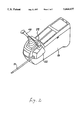
- FIG. 5 is a cross-sectional view showing a structure of only a cutoff bar according to a first embodiment of the cutoff bar
- FIG. 6 is a cross-sectional view showing a structure of a cutoff bar according to a second embodiment of the cutoff bar.
- FIG. 7 is an illustration of a related art construction equipment operation prohibiting apparatus.
- FIG. 1 illustrates a power shovel 11 equipped with an operation prohibiting apparatus according to the preferred embodiment of the invention.
- the power shovel 11 comprises a crawler 13 driven by an engine placed on a base 12 and a bucket 14, an arm 15 and a boom 16 for movably supporting the bucket 14, which are driven by hydraulic control means.
- An operator cab 17 is located on the base 12 and an operating box 19 is provided at both sides of an operator's seat 18 located within the operator cab 17.
- An entryway 20 is formed in the operator cab 17 to allow the operator to get in and out of the cab 17.
- An operation prohibiting apparatus 22 is provided in the entryway 20 at the front side surface of the operating box 19.
- the operation prohibiting apparatus 22 is equipped with a cutoff bar 21 (two embodiments of the cutoff bar 21 will be described) which can be positioned to protrude across the entryway 20 and can be withdrawn therefrom (see FIG. 2).
- the operation prohibiting apparatus includes a base plate 23 positioned vertically, with first and second pivot shafts 24, 25 being attached thereto.
- the first pivot shaft 24 pivotally supports a central portion of a first lever 26 having a generally L-like configuration.
- An operating knob 28 is attached by a fitting screw 27 to a tip portion (one end portion) of the first lever 26 and a connecting pin 29 is fixedly secured to the other end portion of the first lever 26.
- the second pivot shaft 25 pivotally supports a second lever 30 integrally formed with a proximal portion of the cutoff bar 21.
- the second lever 30 has an elongated hole 31 which is loosely engaged with the connecting pin 29.
- a spring supporting pin 32 is fitted into the base plate 23, and a spring 33 is provided between the spring supporting pin 32 and the connecting pin 29.
- the spring 33 has a generally ⁇ -like configuration when viewed from the side as shown in FIG. 3.
- the elastic action of the spring 33 holds the cutoff bar 21 appropriately without wobbling in the vertical position, indicated by a solid line in FIG. 3, and at the horizontal position, indicated by a chain line in the same figure. More specifically, in accordance with the movements of the operating knob 28 the connecting pin 29 is displaceable up and down, in FIG. 3, with respect to an axis 34 connecting the spring supporting pin 32 to the second pivot shaft 25.
- the connecting pin 29 When the connecting pin 29 is located above the axis 34, the second lever 30 is pressed and moved counterclockwise with respect to the second pivot shaft 25 by the elastic pressing force of the spring 33, and the cutoff bar 21 is maintained in a vertical state (hang-down state) by a stopper 35 that limits its movement.
- the connecting pin 29 is located below the axis 34, the second lever 30 is pressed and moved clockwise, in the direction of arrow A, with respect to the second pivot shaft 25 by the elastic action of the spring 33 and the cutoff bar 21 is maintained in the horizontal state (indicated by a chain line in FIG. 3) by means of the movement limiting action of another stopper 36.
- a microswitch 37 is attached to the base plate 23.
- the microswitch 37 is closed by the movement of the first lever 26 actuating a solenoid valve or the like (not shown) to operate a hydraulic system of the construction equipment thereby permitting the construction equipment to work.
- a solenoid valve or the like not shown
- the construction equipment is in an operation-inhibited condition.
- reference numeral 38 designates a connector
- reference numeral 39 designates a cover of the operation breaking apparatus
- reference numeral 48 designates an operating lever.
- the cutoff bar 21 in response to the operating knob 28 being rotationally moved in opposite directions with respect to the first pivot shaft 24, the cutoff bar 21 is displaceable between the horizontal position and the vertical position.
- the cutoff bar 21 In the horizontal position, it blocks the passing of the operator through the entryway 20 of the construction equipment.
- the operator displaces the cutoff bar 21 to the vertical position, the operator can pass in and out of the construction equipment, and the hydraulic driving system of the construction equipment is moved to a locked condition.
- the operating knob 28 is fixedly secured to one end portion of the first lever 26 pivotally supported by the first pivot shaft 24, while the connecting pin 29 is fixedly secured to the other end portion thereof.
- the cutoff bar 21 is fixedly secured to one end portion of the second lever 30 which is pivotally supported by the second pivot shaft 25 and the elongated hole 31 in the other end portion thereof loosely engages with the connecting pin 29. More-over a displacement enlarging mechanism is designed so that the distance between the connecting pin 29 and the second pivot shaft 25 is shorter than the distance between the first pivot shaft 24 and the connecting pin 29. With this arrangement, in response to the slight movement of the operating knob 28, the cutoff bar 21 is movable widely between the horizontal position and the vertical position.
- the operating knob 28 can be located on an upper part of the operating box 19, thereby providing the operation prohibiting apparatus with excellent controllability.
- FIGS. 5 and 6 show alternate embodiments of the cutoff bar 21.
- the cutoff bar 21 shown in FIG. 5 comprises a spring core member 41 having a coil spring section located at one end portion that is fixedly secured to the second lever 30.
- the circumferential portion of the coil spring section 40 is covered with a flexible rubber member 42 while the other portion of the spring core member 41 is covered with a resin-made pipe 43, thus forming a bar-like configuration.
- the cutoff bar 21 can escape damage due to its flexible construction.
- the cutoff bar 21 according to a second embodiment is shown in FIG. 6.
- a metallic pipe 44 is fixedly secured to the second lever 30 and a spring receiving shaft 45 is fixedly secured by means of a pin 46 to a tip portion of the metallic pipe 44.
- a spring core member 41 having a coil spring section 40 is fixedly secured to a tip portion of the spring receiving shaft 45, and the circumferential portion of the coil spring section 40 is covered with a flexible pipe 47 made of a soft material such as a rubber.
- the other portion of the spring core member 41 is covered with a resin-made pipe 49.
- the cutoff bar 21 according to the second embodiment shown in FIG. 6 is provided with a flexible and elastic section comprising the spring section 40 and the flexible pipe 47 which structure saves the cutoff bar 21 from damage.
- the displacement enlarging mechanism is located between the operating knob and the cutoff bar, irrespective of the slight movement of the operating knob, the cutoff bar is movable widely between the horizontal position and the vertical position.
- the operating knob 28 can be placed on an upper portion of the operating box 19, the operation prohibiting apparatus for the construction equipment exhibits excellent controllability.
- a longitudinal portion of the cutoff bar is constructed as a flexible and elastic section, the likelihood of damage to the cutoff bar is minimized.
Abstract
Description
Claims (15)
Applications Claiming Priority (2)
| Application Number | Priority Date | Filing Date | Title |
|---|---|---|---|
| JP7175735A JP2682817B2 (en) | 1995-07-12 | 1995-07-12 | Operation breaker for construction machinery |
| JP7-175735 | 1995-07-12 |
Publications (1)
| Publication Number | Publication Date |
|---|---|
| US5664637A true US5664637A (en) | 1997-09-09 |
Family
ID=16001336
Family Applications (1)
| Application Number | Title | Priority Date | Filing Date |
|---|---|---|---|
| US08/603,763 Expired - Lifetime US5664637A (en) | 1995-07-12 | 1996-02-20 | Operation breaking apparatus for construction equipment |
Country Status (4)
| Country | Link |
|---|---|
| US (1) | US5664637A (en) |
| EP (1) | EP0753629B1 (en) |
| JP (1) | JP2682817B2 (en) |
| DE (1) | DE69613634T2 (en) |
Cited By (17)
| Publication number | Priority date | Publication date | Assignee | Title |
|---|---|---|---|---|
| US5890833A (en) * | 1997-01-15 | 1999-04-06 | Allen Engineering Corporation | Hydraulically controlled riding trowel |
| US6189646B1 (en) * | 1998-11-30 | 2001-02-20 | Clark Equipment Company | Traction lock/momentary override |
| US6299207B1 (en) | 1999-07-14 | 2001-10-09 | Clark Equipment Company | Rear mounted operator restraint bar |
| US6450284B1 (en) * | 1999-04-19 | 2002-09-17 | Hitachi Construction Machinery Co., Ltd. | Cab for construction machinery |
| US20030192732A1 (en) * | 2002-04-11 | 2003-10-16 | James Warkentine | System and method for controlling operation of a loader |
| US20040000799A1 (en) * | 2002-01-07 | 2004-01-01 | Wherley Steven J. | Skid loader door protection apparatus and method |
| US6732829B2 (en) | 2002-01-04 | 2004-05-11 | Clark Equipment Company | Load absorbing operator restraint bar |
| US20040099461A1 (en) * | 2002-11-27 | 2004-05-27 | Miiller Kevin J. | Lateral operator restraint system and position sensor for material handler |
| US20040154427A1 (en) * | 2003-02-12 | 2004-08-12 | Volvo Construction Equipment Holding Sweden Ab | Control lever safety apparatus for heavy equipment |
| US20050035669A1 (en) * | 2003-07-11 | 2005-02-17 | Bares Mark F. | Sensor and interlock on an industrial vehicle |
| US20070080579A1 (en) * | 2005-10-11 | 2007-04-12 | Steinbring David B | Apparatus and method for indicating parking brake non-engagement |
| US20130264138A1 (en) * | 2011-09-27 | 2013-10-10 | Shane Phillips | Safety Control Systems and Methods for Heavy Equipment |
| US9038563B1 (en) * | 2008-11-24 | 2015-05-26 | David B. Steinbring | Apparatus and method for indicating parking brake non-engagement |
| JP2018091015A (en) * | 2016-12-01 | 2018-06-14 | 株式会社日立建機ティエラ | Hydraulic Excavator |
| US10100537B1 (en) | 2017-06-20 | 2018-10-16 | Allen Engineering Corporation | Ventilated high capacity hydraulic riding trowel |
| JP2019039178A (en) * | 2017-08-23 | 2019-03-14 | キャタピラー エス エー アール エル | Operation device of construction machine |
| US11274420B2 (en) * | 2019-07-02 | 2022-03-15 | Gugsoo An | Console box for excavator |
Families Citing this family (7)
| Publication number | Priority date | Publication date | Assignee | Title |
|---|---|---|---|---|
| KR980009677A (en) * | 1996-07-31 | 1998-04-30 | 김무 | Safety lever device for heavy equipment |
| JP2000328604A (en) * | 1999-05-17 | 2000-11-28 | Shin Caterpillar Mitsubishi Ltd | Construction machine |
| JP3461461B2 (en) * | 1999-05-24 | 2003-10-27 | 住友建機製造株式会社 | Safety equipment for construction machinery |
| JP3834694B2 (en) * | 2001-10-02 | 2006-10-18 | 新キャタピラー三菱株式会社 | Passage blocking device for construction machinery |
| JP3942170B2 (en) * | 2002-08-29 | 2007-07-11 | 新キャタピラー三菱株式会社 | Entry / exit blocking device for work machine |
| JP6826549B2 (en) * | 2018-03-09 | 2021-02-03 | 日立建機株式会社 | Construction machinery |
| JP7237035B2 (en) * | 2020-02-27 | 2023-03-10 | 日立建機株式会社 | construction machinery |
Citations (8)
| Publication number | Priority date | Publication date | Assignee | Title |
|---|---|---|---|---|
| US3993157A (en) * | 1975-08-04 | 1976-11-23 | Deere & Company | Door operated control lever latch mechanism |
| US4318571A (en) * | 1980-02-07 | 1982-03-09 | Caterpillar Tractor Co. | Automatic brake control for tilting operator cab |
| EP0066380A2 (en) * | 1981-05-14 | 1982-12-08 | Massey-Ferguson Services N.V. | Lever mechanisms |
| EP0092248A1 (en) * | 1982-04-21 | 1983-10-26 | Hitachi Construction Machinery Co., Ltd. | Universal lever apparatus for hydraulic construction machine |
| US5050700A (en) * | 1989-06-05 | 1991-09-24 | Daewoo Heavy Industries Ltd. | Safety apparatus for a skid-steer loader |
| JPH0430032A (en) * | 1990-05-25 | 1992-02-03 | Hitachi Constr Mach Co Ltd | Working machine |
| US5383532A (en) * | 1991-03-18 | 1995-01-24 | Kabushiki Kaisha Toyoda Jidoshokki Seisakusho | Foot pedal locking device for cargo-handling vehicle |
| US5520258A (en) * | 1993-03-22 | 1996-05-28 | Crown Equipment Corporation, Inc. | Pivotal control panel for electric forklift trucks |
-
1995
- 1995-07-12 JP JP7175735A patent/JP2682817B2/en not_active Expired - Fee Related
-
1996
- 1996-02-20 US US08/603,763 patent/US5664637A/en not_active Expired - Lifetime
- 1996-02-22 DE DE69613634T patent/DE69613634T2/en not_active Expired - Lifetime
- 1996-02-22 EP EP96400361A patent/EP0753629B1/en not_active Expired - Lifetime
Patent Citations (8)
| Publication number | Priority date | Publication date | Assignee | Title |
|---|---|---|---|---|
| US3993157A (en) * | 1975-08-04 | 1976-11-23 | Deere & Company | Door operated control lever latch mechanism |
| US4318571A (en) * | 1980-02-07 | 1982-03-09 | Caterpillar Tractor Co. | Automatic brake control for tilting operator cab |
| EP0066380A2 (en) * | 1981-05-14 | 1982-12-08 | Massey-Ferguson Services N.V. | Lever mechanisms |
| EP0092248A1 (en) * | 1982-04-21 | 1983-10-26 | Hitachi Construction Machinery Co., Ltd. | Universal lever apparatus for hydraulic construction machine |
| US5050700A (en) * | 1989-06-05 | 1991-09-24 | Daewoo Heavy Industries Ltd. | Safety apparatus for a skid-steer loader |
| JPH0430032A (en) * | 1990-05-25 | 1992-02-03 | Hitachi Constr Mach Co Ltd | Working machine |
| US5383532A (en) * | 1991-03-18 | 1995-01-24 | Kabushiki Kaisha Toyoda Jidoshokki Seisakusho | Foot pedal locking device for cargo-handling vehicle |
| US5520258A (en) * | 1993-03-22 | 1996-05-28 | Crown Equipment Corporation, Inc. | Pivotal control panel for electric forklift trucks |
Cited By (24)
| Publication number | Priority date | Publication date | Assignee | Title |
|---|---|---|---|---|
| US5890833A (en) * | 1997-01-15 | 1999-04-06 | Allen Engineering Corporation | Hydraulically controlled riding trowel |
| US6189646B1 (en) * | 1998-11-30 | 2001-02-20 | Clark Equipment Company | Traction lock/momentary override |
| US6450284B1 (en) * | 1999-04-19 | 2002-09-17 | Hitachi Construction Machinery Co., Ltd. | Cab for construction machinery |
| US6299207B1 (en) | 1999-07-14 | 2001-10-09 | Clark Equipment Company | Rear mounted operator restraint bar |
| US6732829B2 (en) | 2002-01-04 | 2004-05-11 | Clark Equipment Company | Load absorbing operator restraint bar |
| US20040000799A1 (en) * | 2002-01-07 | 2004-01-01 | Wherley Steven J. | Skid loader door protection apparatus and method |
| US7080708B2 (en) * | 2002-01-07 | 2006-07-25 | Steven J Wherley | Skid loader door protection apparatus and method |
| US20030192732A1 (en) * | 2002-04-11 | 2003-10-16 | James Warkentine | System and method for controlling operation of a loader |
| US6902024B2 (en) | 2002-11-27 | 2005-06-07 | Clark Equipment Company | Lateral operator restraint system and position sensor for material handler |
| US20040099461A1 (en) * | 2002-11-27 | 2004-05-27 | Miiller Kevin J. | Lateral operator restraint system and position sensor for material handler |
| US6971279B2 (en) * | 2003-02-12 | 2005-12-06 | Volvo Construction Equipment Holding Sweden Ab | Control lever safety apparatus for heavy equipment |
| US20040154427A1 (en) * | 2003-02-12 | 2004-08-12 | Volvo Construction Equipment Holding Sweden Ab | Control lever safety apparatus for heavy equipment |
| US7165472B2 (en) | 2003-02-12 | 2007-01-23 | Volvo Construction Equipment Holding Sweden Ab | Control lever safety apparatus for heavy equipment |
| US20050247152A1 (en) * | 2003-02-12 | 2005-11-10 | Volvo Construction Equipment Holding Sweden Ab | Control lever safety apparatus for heavy equipment |
| US20050035669A1 (en) * | 2003-07-11 | 2005-02-17 | Bares Mark F. | Sensor and interlock on an industrial vehicle |
| US7235901B2 (en) | 2003-07-11 | 2007-06-26 | Clark Equipment Company | Sensor and interlock on an industrial vehicle |
| US20070080579A1 (en) * | 2005-10-11 | 2007-04-12 | Steinbring David B | Apparatus and method for indicating parking brake non-engagement |
| US9038563B1 (en) * | 2008-11-24 | 2015-05-26 | David B. Steinbring | Apparatus and method for indicating parking brake non-engagement |
| US20130264138A1 (en) * | 2011-09-27 | 2013-10-10 | Shane Phillips | Safety Control Systems and Methods for Heavy Equipment |
| US8820463B2 (en) * | 2011-09-27 | 2014-09-02 | Shane Phillips | Safety control systems and methods for heavy equipment |
| JP2018091015A (en) * | 2016-12-01 | 2018-06-14 | 株式会社日立建機ティエラ | Hydraulic Excavator |
| US10100537B1 (en) | 2017-06-20 | 2018-10-16 | Allen Engineering Corporation | Ventilated high capacity hydraulic riding trowel |
| JP2019039178A (en) * | 2017-08-23 | 2019-03-14 | キャタピラー エス エー アール エル | Operation device of construction machine |
| US11274420B2 (en) * | 2019-07-02 | 2022-03-15 | Gugsoo An | Console box for excavator |
Also Published As
| Publication number | Publication date |
|---|---|
| DE69613634D1 (en) | 2001-08-09 |
| JPH0925650A (en) | 1997-01-28 |
| JP2682817B2 (en) | 1997-11-26 |
| DE69613634T2 (en) | 2004-07-29 |
| EP0753629A1 (en) | 1997-01-15 |
| EP0753629B1 (en) | 2001-07-04 |
Similar Documents
| Publication | Publication Date | Title |
|---|---|---|
| US5664637A (en) | Operation breaking apparatus for construction equipment | |
| US4907667A (en) | Full-turn type working machine | |
| US5180198A (en) | Motor driven lock device for trunk lid and the like | |
| CA2539045C (en) | An excavator tool quick attachment device | |
| EP0468771B1 (en) | A construction machine accessory coupling mechanism | |
| US20100095719A1 (en) | Door Lock Device With Safety Switch | |
| DE69401700D1 (en) | Shift lever arrangement | |
| US5277258A (en) | Single lever bulldozer blade control apparatus | |
| US6425729B1 (en) | Arrangement for controlling a work machine | |
| KR20050085291A (en) | Tightening device with lock mechanism | |
| US6128971A (en) | Control device | |
| EP0654725B1 (en) | Mechanism for controlling the position of levers | |
| US5727426A (en) | Mechanism for selecting limits of travel of a lever | |
| EP1664444B1 (en) | Device for attaching a loader to a vehicle | |
| US4917565A (en) | Apparatus for controlling posture of front loader | |
| KR20180097601A (en) | joystick | |
| KR101239479B1 (en) | Option pedal assembly of excavator | |
| CN220441234U (en) | Lifting control device for agricultural machinery | |
| CA2313553C (en) | Actuating arrangement with interlock to prevent unintended actuation when in a non-operating position | |
| CA1120383A (en) | Adjustment method pipelayer control system | |
| US4099449A (en) | Electromagnetic bucket positioner for loader vehicles | |
| US20050042025A1 (en) | Work tool locking device | |
| US4427026A (en) | Limit control for an operating member | |
| US5595091A (en) | Restraint mechanism for a control lever | |
| KR200191968Y1 (en) | The clutch apparatus of bait cast reel |
Legal Events
| Date | Code | Title | Description |
|---|---|---|---|
| AS | Assignment |
Owner name: KANSEI CORPORATION, JAPAN Free format text: ASSIGNMENT OF ASSIGNORS INTEREST;ASSIGNORS:OHTA, MAKOTO;AKAHANE, EIJI;HATA, SEIICHI;AND OTHERS;REEL/FRAME:007934/0652 Effective date: 19960311 Owner name: SHIN CATERPILLAR MITSUBISHI LTD., JAPAN Free format text: ASSIGNMENT OF ASSIGNORS INTEREST;ASSIGNORS:OHTA, MAKOTO;AKAHANE, EIJI;HATA, SEIICHI;AND OTHERS;REEL/FRAME:007934/0652 Effective date: 19960311 |
|
| STCF | Information on status: patent grant |
Free format text: PATENTED CASE |
|
| FEPP | Fee payment procedure |
Free format text: PAYOR NUMBER ASSIGNED (ORIGINAL EVENT CODE: ASPN); ENTITY STATUS OF PATENT OWNER: LARGE ENTITY |
|
| FPAY | Fee payment |
Year of fee payment: 4 |
|
| FPAY | Fee payment |
Year of fee payment: 8 |
|
| AS | Assignment |
Owner name: CATERPILLAR JAPAN LTD., JAPAN Free format text: CHANGE OF NAME;ASSIGNOR:SHIN CATERPILLAR MITSUBISHI LTD.;REEL/FRAME:021531/0563 Effective date: 20080801 Owner name: CATERPILLAR JAPAN LTD.,JAPAN Free format text: CHANGE OF NAME;ASSIGNOR:SHIN CATERPILLAR MITSUBISHI LTD.;REEL/FRAME:021531/0563 Effective date: 20080801 |
|
| FPAY | Fee payment |
Year of fee payment: 12 |
|
| AS | Assignment |
Owner name: CATERPILLAR S.A.R.L.,SWITZERLAND Free format text: ASSIGNMENT OF ASSIGNORS INTEREST;ASSIGNOR:CATERPILLAR JAPAN LTD.;REEL/FRAME:024233/0895 Effective date: 20091231 |