US5893471A - Freely-movable auxiliary hoist for a gantry crane and method for pivoting a load - Google Patents
Freely-movable auxiliary hoist for a gantry crane and method for pivoting a load Download PDFInfo
- Publication number
- US5893471A US5893471A US08/869,400 US86940097A US5893471A US 5893471 A US5893471 A US 5893471A US 86940097 A US86940097 A US 86940097A US 5893471 A US5893471 A US 5893471A
- Authority
- US
- United States
- Prior art keywords
- auxiliary
- trolley
- main
- lifting
- load
- Prior art date
- Legal status (The legal status is an assumption and is not a legal conclusion. Google has not performed a legal analysis and makes no representation as to the accuracy of the status listed.)
- Expired - Lifetime
Links
Images


Classifications
-
- B—PERFORMING OPERATIONS; TRANSPORTING
- B66—HOISTING; LIFTING; HAULING
- B66C—CRANES; LOAD-ENGAGING ELEMENTS OR DEVICES FOR CRANES, CAPSTANS, WINCHES, OR TACKLES
- B66C19/00—Cranes comprising trolleys or crabs running on fixed or movable bridges or gantries
- B66C19/005—Straddle carriers
-
- B—PERFORMING OPERATIONS; TRANSPORTING
- B66—HOISTING; LIFTING; HAULING
- B66C—CRANES; LOAD-ENGAGING ELEMENTS OR DEVICES FOR CRANES, CAPSTANS, WINCHES, OR TACKLES
- B66C13/00—Other constructional features or details
- B66C13/04—Auxiliary devices for controlling movements of suspended loads, or preventing cable slack
- B66C13/08—Auxiliary devices for controlling movements of suspended loads, or preventing cable slack for depositing loads in desired attitudes or positions
-
- B—PERFORMING OPERATIONS; TRANSPORTING
- B66—HOISTING; LIFTING; HAULING
- B66D—CAPSTANS; WINCHES; TACKLES, e.g. PULLEY BLOCKS; HOISTS
- B66D3/00—Portable or mobile lifting or hauling appliances
- B66D3/04—Pulley blocks or like devices in which force is applied to a rope, cable, or chain which passes over one or more pulleys, e.g. to obtain mechanical advantage
Definitions
- the present invention generally relates to a hoist mechanism for an overhead crane and more particularly to a hoist mechanism for lifting and pivoting large panels between horizontal and vertical orientations.
- Overhead gantry cranes are generally known for lifting heavy items.
- such cranes are used for handling large products or containers and transporting them to and from storage or loading containers on ships, trains, trucks, etc.
- These cranes are commonly used in the construction industry as well, handling large construction materials, such as beams, blocks, concrete barriers, pipeline sections, prefabricated components, etc.
- Known cranes of a type referred to herein usually include two parallel horizontal beams which are supported in an elevated fashion by a frame. Each of these horizontal beams is equipped with a lifting hoist trolley which is actively traversible along the horizontal beam in a motorized manner by a positive drive system. Each trolley is a part of a hoist having a separate lifting cable system operable to lift a load, usually with a lifting block suspended by the cable from the trolley.
- the frame is mounted on drivable and steerable wheels so that an operator can drive the crane over a site to lift or deposit a load at a desired location.
- a specific example of a crane application is in the prestressed concrete industry, where gantry cranes are used for handling slabs or panels of formed concrete. These concrete panels are conventionally cast in a horizontal position, but often must be stored and/or transported in a vertical orientation. Therefore, after casting, the concrete panels must not only be lifted, but also must be pivoted from horizontal to vertical orientations for storage or transport. Additionally, at a construction site these concrete panels must be removed from vertical cargo or storage positions and be pivotally positioned horizontally for installation, e.g., as flooring sections.
- Load pivoting has conventionally been accomplished by a crane equipped with two positively-driven hoist trolleys on each of the two horizontal beams, for a total of four positively-driven hoist trolleys per crane. On each beam, one of the hoists is operated to lift one side of the load, while the second hoist is operated to lift the other side of the load. Then, by raising or lowering only one of the hoists, that side of the load is accordingly raised or lowered, "pivoting" the load.
- the two hoist trolleys per beam must be drivably positioned at generally that same panel-width dimension apart from each other, vertically above the respective sides of the horizontal panel.
- the two hoist trolleys on the beam must be positively driven closer to each other during the pivoting operation (while one of the hoists lifts or lowers its side of the panel).
- the two hoist trolleys must be positively driven apart from each other while pivoting a panel from a vertical to a horizontal position.
- cranes are known wherein a single trolley carries two hoists, particularly for lifting and dumping a bucket-like vessel.
- such devices are disclosed in U.S. Pat. Nos. 3,297,170, 3,854,592, 4,144,974, and 4,360,304.
- These trolleys might be suitable for pivoting a bucket or some other load which does not have a substantial width dimension, however, they are not suited for pivoting wide objects such as panels.
- the hoists are fixed closely together in these devices. If used to lift and pivot a load suspended at widely-separated lifting points, the cables would be lifting at non-vertical angles, thereby subjecting them to amplified tensile stress due to both vertical and horizontal force components.
- the present invention overcomes the disadvantages of the prior art by providing an auxiliary hoist assembly to be used on a crane in conjunction with a main hoist assembly, wherein the auxiliary hoist assembly has an independent trolley that is freely moveable along a horizontal support beam instead of being positively controlled by a powered positioning means along the beam. Accordingly, the present invention reduces equipment costs, since there is no need for expensive trolleydriving equipment in conjunction with the auxiliary hoist assembly, such as hydraulic cylinders or motorized drives.
- a crane of the type referred to herein preferably has twin front and rear lifting means (on the front and rear horizontal beams) used in tandem with each other.
- twin front and rear lifting means on the front and rear horizontal beams
- the crane includes cooperating front and rear sets of the described hoist elements.
- the auxiliary hoist assembly includes an auxiliary trolley which is mounted for freely glidable or slidable movement along the beam.
- the beam also supports a main trolley which is not freely-movable, but rather is positively positioned on the beam by a drive means.
- the main and auxiliary trolleys support main and auxiliary lifting cables, respectively, which are selectively operable to lift a load. Because the auxiliary trolley is freely slidable, a horizontal force component through tension on the auxiliary lifting cable causes a corresponding automatic horizontal repositioning of the auxiliary trolley along the beam.
- the auxiliary hoist assembly and main hoist assembly are used in conjunction with each other.
- the load when a load is supported at respective lifting points by the main and auxiliary hoists, the load may be pivoted by actuating one of the hoist cables.
- this pivoting operation is performed by retracting the auxiliary lifting cable while not retracting the main lifting cable. This causes a pivoting moment on the load around the main lifting cable lifting point.
- the auxiliary hoist trolley automatically slides along the beam vertically above its lifting point on the load.
- An advantage of the present invention is that it permits both a main and auxiliary hoist trolleys to be positioned substantially vertically over the respective load lifting points load during pivoting. Because the auxiliary hoist is automatically movable along the beam, both the main lifting cable and auxiliary lifting cable are subjected only to substantially vertical load components.
- a related advantage is that an operator does not have to control the position of an auxiliary trolley along the beam while a load is pivoted.
- a further advantage is that, because the lifting cables are subjected only to substantially vertical lifting loads, the lifting cable are subjected to less tensile stress than in prior art devices wherein lifting cables are subjected to non-vertical lifting angles.
- a device according to the invention is less susceptible to failure and wear, and may also be designed within lower load limits.
- FIG. 1 is a isometric view of a crane utilizing the present invention
- FIG. 2 is a fragmentary perspective view of a rear beam assembly of the crane of FIG. 1 showing the auxiliary lifting cable the main trolley drive mans, but, for clarity, much of the main lifting cable is not shown;
- FIG. 3 is a fragmentary front elevation of the front horizontal beam of the crane, showing the auxiliary hoist assembly and the main trolley;
- FIG. 4 is a side elevation of the auxiliary trolley
- FIG. 5 is a fragmentary perspective view of the beam assembly of the crane of FIG. 1, illustrating routing of the main lifting cable but, not showing the main trolley drive means or auxiliary lifting cable routing;
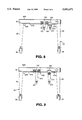
- FIGS. 6-9 illustrate a crane during various stages of a lifting and pivoting cycle:
- FIGS. 6 is a fragmentary rear elevation of a crane according to an embodiment of the invention wherein a main and auxiliary hoist are lifting a panel in horizontal orientation;
- FIG. 7 is a fragmentary rear elevation of the crane of FIG. 6 wherein the main and auxiliary hoists are supporting the panel in a substantially vertical orientation, showing the angle ⁇ that a panel is pivoted from a horizontal to a substantially vertical orientation;
- FIG. 8 is a fragmentary rear elevation of a crane wherein the main trolley has been driven and abutting contact against the auxiliary trolley to reposition the auxiliary trolley for lifting a horizontally-oriented load;
- FIG. 9 is a fragmentary rear elevation of the crane of FIG. 8 wherein the main trolley has been driven away from the repositioned auxiliary trolley so that both the main and auxiliary lifting hoist are ready to lift a horizontally-oriented load.
- FIG. 1 shows an overhead crane 20 having a frame 22.
- the frame 22 includes four corner-located vertical columns 24, 26, 28, and 30 which support front and rear transversely-mounted elevated horizontal beams 32F and 32R, respectively.
- the frame 22 also includes a pair of side members 36 connected between respective columns in a front-to-back alignment at the right and left of the crane 20.
- Wheels 38 are mounted under the columns 24, 26, 28, 30 for drivably maneuvering the crane 20 over the ground.
- a cab 40 is mounted on one of the side members 36 of the frame from which an operator can drive and operate the crane 20.
- the crane 20 is configured to be maneuverable to position the elevated horizontal beams 32F, 32R over large loads to be handled.
- the front and rear horizontal beams 32F, 32R are each provided with a main hoist assembly 100 and, according to the invention, an auxiliary hoist assembly 200.
- FIGS. 2 and 3 illustrate the hoist assemblies 100, 200 at rear and front horizontal beams 32R, 32F, respectively.
- both the front and rear of the crane 20 are equipped with main and auxiliary hoist assemblies arranged at like sides of the crane.
- the horizontal beams 32F and 32R are I-beams, each having a bottom flange 42.
- the main hoist assembly 100 includes a main trolley 102 which guidably rides along the bottom flange 42.
- the main trolley 102 includes a main trolley body 104 to which a plurality of roller wheels 106 are mounted for rollably supporting the main trolley 102 on the bottom flange 42.
- the main trolley 102 further includes a plurality of pulleys or sheaves 108 rotatably mounted to the main trolley body 104.
- each main hoist assembly 100 For vertically lifting a load toward the main trolley 102, each main hoist assembly 100 includes a main lifting cable 110 which is guided over the sheaves 108.
- the main lifting cable 110 operably supports a main hook block 112 hanging below the main trolley 102.
- the routing of the main lifting cable 110 and other details of the main hoist assembly are described in greater detail below in connection with FIG. 5.
- FIG. 2 illustrates one conventional drive means for positively positioning the main trolley 102.
- a motor-operated friction drive 114 moves a looped wire rope or drive cable 116 having ends oppositely secured to the main trolley 102.
- the drive cable 116 follows along the length of the horizontal beam 32R, passing over a rotatable pulley 118 at side of the frame 22 opposite the friction drive 114.
- the looped drive cable 116 is thereby caused to circulate, positively driving the main trolley 102 to desired positions along the beam 32R.
- Other drive means are possible, such as a conventional chain drive or other drives.
- each auxiliary hoist assembly 200 includes an auxiliary trolley 202 which is freely slidable along the respective horizontal beam 32F, 32R.
- the auxiliary trolley 202 has a trolley body 204, preferably including a plurality of roller wheels 206, which are also shown in FIG. 4.
- the roller wheels 206 are positioned to rollably glide along an upwardly-facing surface of the bottom flange 42.
- Also rotatably mounted to the trolley body 204 are one or more pulleys or sheaves 208.
- the auxiliary hoist assembly 200 For vertically lifting a load toward the auxiliary trolley 202, the auxiliary hoist assembly 200 includes an auxiliary lifting cable 210 which is movably supported on the auxiliary trolley 202 by the sheaves 208.
- a first end of the auxiliary lifting cable 210 is coiled around an auxiliary hoist drum 220 which is rotatably mounted to the frame 22 near the left column 26 (FIG. 2), 24 (FIG. 3).
- the auxiliary hoist drum 220 has a sprocket 222 fixed at one side.
- the sprocket is drivable by a motor 224 via a gear box and drive chain 228 to rotate the drum 220 for feeding and retracting the auxiliary lifting cable 210.
- the motor 224 is preferably a hydraulic motor, but the motor 224 may instead be electric or some other type of motor.
- the auxiliary lifting cable 210 extends from the drum 220 parallel to an underside of the horizontal beam 32F, 32R, passing freely through the main trolley 102 to the auxiliary trolley 202.
- the auxiliary lifting cable 210 then forms a loop over the auxiliary hoist trolley 202 in a manner guidably supported by the rotating sheaves 208, this loop supporting an auxiliary hook block 212 hanging below the auxiliary trolley 202.
- the auxiliary lifting cable 210 extends from the auxiliary hoist drum 220 over a first one of the sheaves 208, extends vertically downwardly to wrap under a sheave 208 which is rotatably mounted to the hoist block 212. From the hoist block 212, the auxiliary lifting cable 210 turns upwardly to the trolley 202 through which the cable is rollably guided by a second one of the sheaves 208 of the auxiliary trolley 202. From there, the auxiliary cable 210 follows below the horizontal beam to a dead end mount 214 secured to the frame 22 opposite the auxiliary hoist drum 220. In the embodiment illustrated in FIG. 2, the dead end mount 214 is secured to an underside of the horizontal beam near the right column 30, opposite the drum 220.
- auxiliary lifting cable 210 is selectively fed or retracted, resulting in a respective lowering or raising of the auxiliary hook block 212.
- the auxiliary trolleys 202 are freely slidable along the horizontal beams 32F, 32R. As the auxiliary trolleys 202 slide, the auxiliary lifting cable 210 guidably circulates over the sheaves 208, passing through the auxiliary trolley body 204. Some frictional resistance is present at the sheaths 208, cable 210, and roller wheels 206, however a significant horizontal component of tension in the auxiliary hoist cable 210 below the auxiliary trolley 202 in a direction parallel to the beam will overcome such friction. Accordingly, the auxiliary trolley 202 automatically glides along the beam in response to the horizontal cable tension component so that the auxiliary trolley 202 effectively maintains a substantially vertical position over the auxiliary hook block 212.
- the auxiliary hook block 212 ideally would be kept vertically under the auxiliary trolley 202, the discussed frictional effects in actual use cause the alignment to be normally somewhat non-vertical.
- the term “substantially vertical” includes this slightly non-vertical alignment as within the scope of the invention, and also the term “substantial horizontal force component” is meant as a force at least great enough to overcome the friction of the auxiliary trolley 202.
- the auxiliary trolley 202 is non-driven in relation to its position on the horizontal beam 32F, 32R.
- the conventional main trolley 102 is positively positioned on the beam 32F, 32R via a driving means, which is illustrated in FIG. 2.
- the auxiliary trolley 202 is shown in greater detail.
- the trolley 202 has a total of four roller wheels 206 which are arranged in opposing pairs so that two of the roller wheels ride on each side of the bottom flange 42 (FIGS. 2 and 3).
- Each of the illustrated roller wheels 206 has an annular flange which overhangs an edge of the beam flange 42 to guidably position the roller wheel 26.
- the auxiliary trolley body 204 is generally U-shaped as illustrated in FIG. 4, so that the roller wheels 206 are mounted at upper portion of the trolley body 204.
- the sheaves 208 are rollably mounted at a lower portion of the trolley body 204, preferably, on a common axle 216.
- each main lifting hoist 100 includes a conventional cable lifting system, such as that shown in FIG. 5.
- the main lifting cable 110 has opposite ends coiled around main lifting drums 120 which are drivably rotatable by a motor.
- the main lifting cable 110 is guided over a plurality of pulleys 122, 124, 126 mounted to the horizontal beam 32F and extends over the sheaves 108 of the main trolley 102 to support the main hook block 112. Actuation of the main lifting drums 120 is effective to retract or feed the main lifting cable 110, resulting in the raising or lowering of the main hook block 112.
- FIGS. 6-9 illustrate the main hoist assembly 100 and auxiliary hoist assembly 200in successive stages of cooperative operation during a process of lifting and pivoting a panel-like load, then resetting the trolleys in position for repeating the process.
- FIG. 6 shows the main hook block 112 and auxiliary hook block 212 secured at separate connecting points of a horizontal panel 300.
- the main and auxiliary lifting cables 110, 210 have been set so that the respective main and auxiliary hook blocks 112, 212 are at about the same vertical heights.
- the main and auxiliary trolleys 102, 202 are positioned substantially vertically above the respective connection points of the hook blocks 112, 212 to the panel 300.
- the auxiliary hoist drum 220 is then actuated to retract the auxiliary lifting cable 210, causing an upward lifting of the auxiliary hook block 212.
- the panel 300 is caused to pivot, as illustrated in FIG. 7.
- the panel 300 has pivoted by an angle ⁇ to a substantially vertical position. (It is recognized that the dimensions of the trolleys 102 and 202 prevent a completely vertical orientation of the panel 300 unless either main or auxiliary the lifting cable is slackened).
- the main trolley 102 is undriven, remaining stationary, however, the auxiliary trolley 202 automatically maintains a substantially vertical position over the auxiliary hook block 212, moving a distance d along the horizontal beam to a position where the auxiliary trolley 202 abuts the main trolley 102.
- a rubber bumper 109 is mounted to the main trolley body 104 for cushioning contact between the main trolley 102 and auxiliary trolley 202. The panel 300 may then be released in the substantially vertical position.
- the main trolley 102 is positively driven to push the auxiliary trolley 202 to the desired position, as shown in FIG. 8.
- the main trolley 102 can then be driven in the opposite direction, returning to its initial lifting position, shown in FIG. 9, so that the lifting and pivoting cycle can be repeated.
- the device of the invention may also be used in a reverse manner to lift a panel from a substantially vertical position and pivot it to a horizontal position.
- the auxiliary trolley 202 is initially positioned close to the main trolley 102, as shown in FIG. 7.
- the auxiliary lifting cable 210 is then fed out by the drum 220 in order to lower the auxiliary lifting block 212 and pivot the panel 300 to a horizontal position, as shown in FIG. 6.
- the auxiliary trolley follows substantially vertically above the auxiliary hook block 212, automatically traveling the distance d (FIG. 7) when the panel 300 pivots.
- the crane 20 of the invention could also be used to pivot a panel 300 by feeding or retracting the main lifting cable 110 while the length of the auxiliary lifting cable 210 remains the same.
- the auxiliary trolley 202 will still automatically freely slide along the horizontal beam 32 so that the main and auxiliary trolleys 102, 202 maintain a substantially vertical position over the their respective blocks 112, 212 and associated lifting points.
- FIGS. 6-9 show the hook blocks 112 and 212 connected at opposite sides of the panel 300, separated by the entire panel width. While such a connection would achieve a desirable pivoting moment, it is not necessary that the connection points be at the panel ends. Rather, the hook blocks 112, 212 could be connected at various mid-points across the panel width, if the respective connection points are separated by a distance. In fact, in one embodiment, the main hook block 112 may be connected at a center of gravity of the panel 300 while the auxiliary block 212 is connected at some distance away, so that the auxiliary lifting cable 210 is required only to provide a pivoting moment without actually exerting a lifting force.
- actuation levers are preferably also mounted conveniently in the cab 40.
- Front and rear main lifting actuating levers may be located side-by-side, and front and rear main trolley driving actuation levers may be located side-by-side.
- Levers for actuating the front and rear motors 224 to move the auxiliary lifting cables 210 may also mounted side-by-side in a group. This group of auxiliary cable actuation levers may be mounted beside the main lifting cable actuation levers to permit convenient actuation of simultaneous four-point lifting of a load with the main and auxiliary hoist assemblies.
- the main and auxiliary lifting hoist assemblies 100, 200 are preferably cooperatively tuned such that the main hoist blocks 112 and auxiliary hoist blocks 212 lift and lower at the same rate upon actuation.
- a variable displacement load sensing pump is provided with manually-actuated direction valves (one for each hoist) individually actuatable by the aforementioned levers. Lifting speed of the hook blocks 112, 212 is controlled by the amount that the direction valves are opened.
- auxiliary lifting cable 210 makes one U-pass through the auxiliary hook block 212, but that the main lifting cable 110 makes two U-passes through the main hook block 112. Therefore, the main cable 110 must be retracted at twice the rate of the auxiliary cable 210 in order to lift the main hook block 112 and auxiliary hook block 212 at the same rate.
- an auxiliary hoist assembly according to the invention which loops the auxiliary lifting cable 210 more than once, e.g. making two U-passes through the auxiliary lifting block.
Abstract
Description
Claims (18)
Priority Applications (1)
| Application Number | Priority Date | Filing Date | Title |
|---|---|---|---|
| US08/869,400 US5893471A (en) | 1997-06-05 | 1997-06-05 | Freely-movable auxiliary hoist for a gantry crane and method for pivoting a load |
Applications Claiming Priority (1)
| Application Number | Priority Date | Filing Date | Title |
|---|---|---|---|
| US08/869,400 US5893471A (en) | 1997-06-05 | 1997-06-05 | Freely-movable auxiliary hoist for a gantry crane and method for pivoting a load |
Publications (1)
| Publication Number | Publication Date |
|---|---|
| US5893471A true US5893471A (en) | 1999-04-13 |
Family
ID=25353483
Family Applications (1)
| Application Number | Title | Priority Date | Filing Date |
|---|---|---|---|
| US08/869,400 Expired - Lifetime US5893471A (en) | 1997-06-05 | 1997-06-05 | Freely-movable auxiliary hoist for a gantry crane and method for pivoting a load |
Country Status (1)
| Country | Link |
|---|---|
| US (1) | US5893471A (en) |
Cited By (41)
| Publication number | Priority date | Publication date | Assignee | Title |
|---|---|---|---|---|
| US6123518A (en) * | 1998-03-13 | 2000-09-26 | Mi-Jack Products, Inc. | Integral shaft coupling for a flexible driveplate in a pump drivetrain |
| US6428267B1 (en) * | 1998-09-30 | 2002-08-06 | Gilman Engineering & Manufacturing Co., Llc | Pick and place device having two parallel axes |
| US6598859B1 (en) * | 2001-05-31 | 2003-07-29 | Magnetek, Inc. | Multiple hoist synchronization apparatus and method |
| US20050211654A1 (en) * | 2004-03-25 | 2005-09-29 | Mhe Technologies, Inc. | Gondola tipping system |
| US20060102578A1 (en) * | 2004-08-03 | 2006-05-18 | Mi-Jack Products, Inc. | Variable-speed load-dependent drive and hoist system |
| US20070095776A1 (en) * | 2005-10-31 | 2007-05-03 | Wierzba Jerry J | Panel turner for gantry crane |
| US20070095777A1 (en) * | 2005-10-31 | 2007-05-03 | Wierzba Jerry J | Powered auxiliary hoist mechanism for a gantry crane |
| US20070292209A1 (en) * | 2005-10-11 | 2007-12-20 | Bishop Richard B | Boat portage apparatus and method |
| US20090097935A1 (en) * | 2007-10-11 | 2009-04-16 | Noell Mobile Systems Gmbh | Gantry stacker with two side-by-side spreaders |
| US20090314574A1 (en) * | 2008-06-20 | 2009-12-24 | Holzman Malcolm | Movable acoustic shell assembly |
| US20100181788A1 (en) * | 2009-01-21 | 2010-07-22 | Konecranes PIc | Dual chain hoist arrangement |
| US20110100753A1 (en) * | 2008-07-09 | 2011-05-05 | Johannes Tarkiainen | Trolley of overhead crane |
| US20110180506A1 (en) * | 2008-10-09 | 2011-07-28 | Hans Kunz Gesellschaft M.B.H. | Gantry cane |
| EP2364949A1 (en) * | 2010-03-12 | 2011-09-14 | Vestas Wind Systems A/S | Methods and apparatus for handling a tower section of a wind turbine with a crane |
| US20110272376A1 (en) * | 2010-05-10 | 2011-11-10 | Korea Advanced Institute Of Science And Technology | Trolley assembly for a crane and a crane therewith |
| EP2423147A1 (en) * | 2010-08-31 | 2012-02-29 | Demag Cranes & Components GmbH | Assembly for rotating a load |
| CN102616667A (en) * | 2011-01-31 | 2012-08-01 | 上海振华重工(集团)股份有限公司 | Double-upper trolley gantry crane |
| US20130015042A1 (en) * | 2011-07-11 | 2013-01-17 | Ftsi, Llc | Engagement article, load positioning system, and process for positioning loads |
| CN103287988A (en) * | 2013-06-25 | 2013-09-11 | 苏州速腾电子科技有限公司 | A mobile gantry frame |
| US20140007430A1 (en) * | 2011-05-26 | 2014-01-09 | Tarik Ozkul | Method and Apparatus for Sculpting Parabolic Shape |
| US20140027400A1 (en) * | 2006-11-23 | 2014-01-30 | Henrik Fomsgaard Lynderup | Method and device for mounting of wind turbine blades |
| US20140348623A1 (en) * | 2013-05-23 | 2014-11-27 | Shanghai YeSheng Mechanical & Electrical Control Technology Co., LTD | Construction Apparatus and Method for Lifting and Sliding Object over Barrier in Horizontal Direction |
| US20150008205A1 (en) * | 2013-07-04 | 2015-01-08 | Liebherr-Werk Ehingen Gmbh | Method of assembling a crane and coupling section, telescopic boom and crane |
| WO2015001149A1 (en) * | 2013-07-05 | 2015-01-08 | Pacadar S.A.U. | Method of pre-assembly and system for handling the tower of a wind turbine |
| CN104692260A (en) * | 2013-12-09 | 2015-06-10 | 烟台中集来福士海洋工程有限公司 | Portal crane |
| US20150203334A1 (en) * | 2014-01-17 | 2015-07-23 | Mi-Jack Products, Inc. | Crane Trolley and Hoist Position Homing and Velocity Synchronization |
| CN105152030A (en) * | 2015-06-26 | 2015-12-16 | 中化二建集团有限公司 | Method for hoisting Fischer-Tropsch synthesis reactor by taking gantry crane as main crane and achieving tail lifting through single gantry |
| FR3024133A1 (en) * | 2014-07-28 | 2016-01-29 | Airbus Operations Sas | PORTIC FOR CARRYING A LOAD |
| CN105463996A (en) * | 2015-12-25 | 2016-04-06 | 上海建工四建集团有限公司 | Turnover device and method used for single crane hoisting of prefabricated stand pillars |
| CN105858490A (en) * | 2016-05-18 | 2016-08-17 | 无锡石油化工起重机有限公司 | Gantry crane with smoke alarm device |
| US20160311665A1 (en) * | 2012-03-20 | 2016-10-27 | Alion Energy, Inc. | Gantry crane vehicles and methods for photovoltaic arrays |
| US20170015532A1 (en) * | 2014-04-04 | 2017-01-19 | Konecranes Global Corporation | Moving crane |
| US20170129748A1 (en) * | 2015-11-06 | 2017-05-11 | High Concrete Group Llc | Slider for use with a crane |
| CN108473285A (en) * | 2015-12-03 | 2018-08-31 | 天际起重机科技有限公司 | Balanced cantilever formula device for feeding |
| CN108639962A (en) * | 2018-04-26 | 2018-10-12 | 中国二十冶集团有限公司 | Large-scale walking beam is crossed across installation method |
| US20180319633A1 (en) * | 2015-10-28 | 2018-11-08 | Konecranes Global Corporation | Method for operating at least two lifting means in a group operation, and assembly comprising at least two lifting means |
| CN109052169A (en) * | 2018-09-03 | 2018-12-21 | 江苏长风海洋装备制造有限公司 | A kind of hoisting transportation technique for offshore wind farm jacket |
| CN110203834A (en) * | 2019-07-08 | 2019-09-06 | 中国机械工业建设集团有限公司 | The hanging apparatus and hanging method of large-scale paper machine " Z " type cantilever beam structure |
| CN110566244A (en) * | 2019-10-22 | 2019-12-13 | 湖南五新隧道智能装备股份有限公司 | Trolley |
| EP3608488A1 (en) * | 2018-08-10 | 2020-02-12 | Drehtainer GmbH Spezial Container- Und Fahrzeugbau | Device, assembly and method for positioning containers |
| CN112249889A (en) * | 2020-11-01 | 2021-01-22 | 湖南铁道职业技术学院 | Movable device for maintaining high-speed rail |
Citations (16)
| Publication number | Priority date | Publication date | Assignee | Title |
|---|---|---|---|---|
| US1430009A (en) * | 1920-05-14 | 1922-09-26 | Robert J Harry | Crane trolley |
| US3075603A (en) * | 1959-06-29 | 1963-01-29 | Drott Mfg Corp | Vehicle steering system |
| US3081883A (en) * | 1960-08-03 | 1963-03-19 | Manning Maxwell & Moore Inc | Steerable gantry crane |
| US3297170A (en) * | 1965-02-23 | 1967-01-10 | Kerma Corp | Furnace charger crane |
| US3389809A (en) * | 1967-06-20 | 1968-06-25 | Wilson Ray | Overhead crane with main beam |
| DE1756299A1 (en) * | 1968-05-03 | 1970-03-12 | Krupp Gmbh | Gantry or traveling crane |
| US3513987A (en) * | 1967-08-12 | 1970-05-26 | Gen Electric Canada | Three-crane lifting beam |
| US3854592A (en) * | 1973-05-25 | 1974-12-17 | Ederer Inc | Variable capacity crane hoist |
| US3874516A (en) * | 1972-12-29 | 1975-04-01 | Ishikawajima Harima Heavy Ind | Device for preventing the swaying of the suspending means in a crane |
| US3999672A (en) * | 1975-04-30 | 1976-12-28 | Brock Gibson E | Overrunning yoke self-loading carrier |
| US4144974A (en) * | 1976-05-13 | 1979-03-20 | Ederer Incorporated | Method of temporarily increasing the load capacity of a powered drum hoist |
| US4360304A (en) * | 1980-09-26 | 1982-11-23 | Amca International Corporation | Extendable crane trolley and method |
| US4360112A (en) * | 1980-09-26 | 1982-11-23 | Amca International Corporation | Two-way extendable crane trolley |
| US4544070A (en) * | 1983-02-16 | 1985-10-01 | Mi-Jack Products, Inc. | Sway control arrangement for hoist systems |
| US4657150A (en) * | 1986-04-21 | 1987-04-14 | Mi-Jack Products, Inc. | Overhead crane having bridge mounted for differential movement |
| US4749328A (en) * | 1986-10-20 | 1988-06-07 | Mi-Jack Products, Inc. | Auxiliary hoist grapple |
-
1997
- 1997-06-05 US US08/869,400 patent/US5893471A/en not_active Expired - Lifetime
Patent Citations (16)
| Publication number | Priority date | Publication date | Assignee | Title |
|---|---|---|---|---|
| US1430009A (en) * | 1920-05-14 | 1922-09-26 | Robert J Harry | Crane trolley |
| US3075603A (en) * | 1959-06-29 | 1963-01-29 | Drott Mfg Corp | Vehicle steering system |
| US3081883A (en) * | 1960-08-03 | 1963-03-19 | Manning Maxwell & Moore Inc | Steerable gantry crane |
| US3297170A (en) * | 1965-02-23 | 1967-01-10 | Kerma Corp | Furnace charger crane |
| US3389809A (en) * | 1967-06-20 | 1968-06-25 | Wilson Ray | Overhead crane with main beam |
| US3513987A (en) * | 1967-08-12 | 1970-05-26 | Gen Electric Canada | Three-crane lifting beam |
| DE1756299A1 (en) * | 1968-05-03 | 1970-03-12 | Krupp Gmbh | Gantry or traveling crane |
| US3874516A (en) * | 1972-12-29 | 1975-04-01 | Ishikawajima Harima Heavy Ind | Device for preventing the swaying of the suspending means in a crane |
| US3854592A (en) * | 1973-05-25 | 1974-12-17 | Ederer Inc | Variable capacity crane hoist |
| US3999672A (en) * | 1975-04-30 | 1976-12-28 | Brock Gibson E | Overrunning yoke self-loading carrier |
| US4144974A (en) * | 1976-05-13 | 1979-03-20 | Ederer Incorporated | Method of temporarily increasing the load capacity of a powered drum hoist |
| US4360304A (en) * | 1980-09-26 | 1982-11-23 | Amca International Corporation | Extendable crane trolley and method |
| US4360112A (en) * | 1980-09-26 | 1982-11-23 | Amca International Corporation | Two-way extendable crane trolley |
| US4544070A (en) * | 1983-02-16 | 1985-10-01 | Mi-Jack Products, Inc. | Sway control arrangement for hoist systems |
| US4657150A (en) * | 1986-04-21 | 1987-04-14 | Mi-Jack Products, Inc. | Overhead crane having bridge mounted for differential movement |
| US4749328A (en) * | 1986-10-20 | 1988-06-07 | Mi-Jack Products, Inc. | Auxiliary hoist grapple |
Cited By (77)
| Publication number | Priority date | Publication date | Assignee | Title |
|---|---|---|---|---|
| US6123518A (en) * | 1998-03-13 | 2000-09-26 | Mi-Jack Products, Inc. | Integral shaft coupling for a flexible driveplate in a pump drivetrain |
| US6428267B1 (en) * | 1998-09-30 | 2002-08-06 | Gilman Engineering & Manufacturing Co., Llc | Pick and place device having two parallel axes |
| US6598859B1 (en) * | 2001-05-31 | 2003-07-29 | Magnetek, Inc. | Multiple hoist synchronization apparatus and method |
| US6956339B1 (en) | 2001-05-31 | 2005-10-18 | Magnetek, Inc. | Multiple hoist synchronization apparatus and method |
| US20050211654A1 (en) * | 2004-03-25 | 2005-09-29 | Mhe Technologies, Inc. | Gondola tipping system |
| US20060102578A1 (en) * | 2004-08-03 | 2006-05-18 | Mi-Jack Products, Inc. | Variable-speed load-dependent drive and hoist system |
| US7353959B2 (en) | 2004-08-03 | 2008-04-08 | Mi-Jack Products, Inc. | Variable-speed load-dependent drive and hoist system |
| US9302891B2 (en) | 2005-02-15 | 2016-04-05 | Marine Travelift, Inc. | Powered auxiliary hoist mechanism for a gantry crane |
| US7517183B2 (en) * | 2005-03-23 | 2009-04-14 | Mhe Technologies, Inc. | Gondola tipping system |
| US20070292209A1 (en) * | 2005-10-11 | 2007-12-20 | Bishop Richard B | Boat portage apparatus and method |
| US20070095776A1 (en) * | 2005-10-31 | 2007-05-03 | Wierzba Jerry J | Panel turner for gantry crane |
| US20070095777A1 (en) * | 2005-10-31 | 2007-05-03 | Wierzba Jerry J | Powered auxiliary hoist mechanism for a gantry crane |
| US7451883B2 (en) | 2005-10-31 | 2008-11-18 | Marine Travelift, Inc. | Panel turner for gantry crane |
| US20090045156A1 (en) * | 2005-10-31 | 2009-02-19 | Marine Travelift, Inc. | Panel turner for a gantry crane |
| US7546929B2 (en) | 2005-10-31 | 2009-06-16 | Marine Travelift, Inc. | Powered auxiliary hoist mechanism for a gantry crane |
| US20090230072A1 (en) * | 2005-10-31 | 2009-09-17 | Marine Travelift, Inc. | Powered Auxiliary Hoist Mechanism |
| US20110192816A1 (en) * | 2005-10-31 | 2011-08-11 | Marine Travellift, Inc. | Powered Auxiliary Hoist Mechanism for a Gantry Crane |
| US7926671B2 (en) | 2005-10-31 | 2011-04-19 | Marine Travelift, Inc. | Powered auxiliary hoist mechanism |
| US7913864B2 (en) | 2005-10-31 | 2011-03-29 | Marine Travelift, Inc. | Panel turner for a gantry crane |
| US20140027400A1 (en) * | 2006-11-23 | 2014-01-30 | Henrik Fomsgaard Lynderup | Method and device for mounting of wind turbine blades |
| US9009964B2 (en) * | 2006-11-23 | 2015-04-21 | Siemens Aktiengesellschaft | Device for mounting of wind turbine blades |
| US7731041B2 (en) * | 2007-10-11 | 2010-06-08 | Noell Mobile Systems Gmbh | Gantry stacker with two side-by-side spreaders |
| US20090097935A1 (en) * | 2007-10-11 | 2009-04-16 | Noell Mobile Systems Gmbh | Gantry stacker with two side-by-side spreaders |
| US7815011B2 (en) * | 2008-06-20 | 2010-10-19 | Holzman Moss Architecture, Llp | Movable acoustic shell assembly |
| US20090314574A1 (en) * | 2008-06-20 | 2009-12-24 | Holzman Malcolm | Movable acoustic shell assembly |
| US9090437B2 (en) * | 2008-07-09 | 2015-07-28 | Konecranes Plc | Trolley of overhead crane |
| US20110100753A1 (en) * | 2008-07-09 | 2011-05-05 | Johannes Tarkiainen | Trolley of overhead crane |
| US20110180506A1 (en) * | 2008-10-09 | 2011-07-28 | Hans Kunz Gesellschaft M.B.H. | Gantry cane |
| RU2507145C2 (en) * | 2009-01-21 | 2014-02-20 | КОНЕКРЕЙНС ПиЭлСи | Lifter with two chains |
| JP2010168219A (en) * | 2009-01-21 | 2010-08-05 | Konecranes Plc | Double chain hoist device |
| US8226137B2 (en) * | 2009-01-21 | 2012-07-24 | Konecranes Plc | Dual chain hoist arrangement |
| EP2210849A1 (en) * | 2009-01-21 | 2010-07-28 | Konecranes Plc | Double chain hoist assembly |
| US20100181788A1 (en) * | 2009-01-21 | 2010-07-22 | Konecranes PIc | Dual chain hoist arrangement |
| CN101786573A (en) * | 2009-01-21 | 2010-07-28 | 科尼起重机设备有限公司 | Double chain hoist assembly |
| US20110221215A1 (en) * | 2010-03-12 | 2011-09-15 | Vestas Wind Systems A/S | Methods and apparatus for handling a tower section of a wind turbine with a crane |
| EP2364949A1 (en) * | 2010-03-12 | 2011-09-14 | Vestas Wind Systems A/S | Methods and apparatus for handling a tower section of a wind turbine with a crane |
| US20110272376A1 (en) * | 2010-05-10 | 2011-11-10 | Korea Advanced Institute Of Science And Technology | Trolley assembly for a crane and a crane therewith |
| EP2423147A1 (en) * | 2010-08-31 | 2012-02-29 | Demag Cranes & Components GmbH | Assembly for rotating a load |
| CN102616667A (en) * | 2011-01-31 | 2012-08-01 | 上海振华重工(集团)股份有限公司 | Double-upper trolley gantry crane |
| US20140007430A1 (en) * | 2011-05-26 | 2014-01-09 | Tarik Ozkul | Method and Apparatus for Sculpting Parabolic Shape |
| US8789682B2 (en) * | 2011-07-11 | 2014-07-29 | Tait Towers Manufacturing, LLC | Engagement article, load positioning system, and process for positioning loads |
| US20130015042A1 (en) * | 2011-07-11 | 2013-01-17 | Ftsi, Llc | Engagement article, load positioning system, and process for positioning loads |
| US10669132B2 (en) * | 2012-03-20 | 2020-06-02 | Alion Energy, Inc. | Gantry crane vehicles and methods for photovoltaic arrays |
| US20160311665A1 (en) * | 2012-03-20 | 2016-10-27 | Alion Energy, Inc. | Gantry crane vehicles and methods for photovoltaic arrays |
| US20140348623A1 (en) * | 2013-05-23 | 2014-11-27 | Shanghai YeSheng Mechanical & Electrical Control Technology Co., LTD | Construction Apparatus and Method for Lifting and Sliding Object over Barrier in Horizontal Direction |
| US9278831B2 (en) * | 2013-05-23 | 2016-03-08 | Guangzhou Construction Engineering Co., Ltd. | Construction apparatus and method for lifting and sliding object over barrier in horizontal direction |
| CN103287988A (en) * | 2013-06-25 | 2013-09-11 | 苏州速腾电子科技有限公司 | A mobile gantry frame |
| US9376293B2 (en) * | 2013-07-04 | 2016-06-28 | Liebherr-Werk Ehingen Gmbh | Method of assembling a crane and coupling section, telescopic boom and crane |
| US20150008205A1 (en) * | 2013-07-04 | 2015-01-08 | Liebherr-Werk Ehingen Gmbh | Method of assembling a crane and coupling section, telescopic boom and crane |
| WO2015001149A1 (en) * | 2013-07-05 | 2015-01-08 | Pacadar S.A.U. | Method of pre-assembly and system for handling the tower of a wind turbine |
| CN104692260A (en) * | 2013-12-09 | 2015-06-10 | 烟台中集来福士海洋工程有限公司 | Portal crane |
| US10196242B2 (en) | 2014-01-17 | 2019-02-05 | Mi-Jack Products, Inc. | Crane trolley and hoist position homing and velocity synchronization |
| US20150203334A1 (en) * | 2014-01-17 | 2015-07-23 | Mi-Jack Products, Inc. | Crane Trolley and Hoist Position Homing and Velocity Synchronization |
| US9321614B2 (en) * | 2014-01-17 | 2016-04-26 | Mi-Jack Products, Inc. | Crane trolley and hoist position homing and velocity synchronization |
| US20170015532A1 (en) * | 2014-04-04 | 2017-01-19 | Konecranes Global Corporation | Moving crane |
| FR3024133A1 (en) * | 2014-07-28 | 2016-01-29 | Airbus Operations Sas | PORTIC FOR CARRYING A LOAD |
| CN105152030A (en) * | 2015-06-26 | 2015-12-16 | 中化二建集团有限公司 | Method for hoisting Fischer-Tropsch synthesis reactor by taking gantry crane as main crane and achieving tail lifting through single gantry |
| US10723595B2 (en) * | 2015-10-28 | 2020-07-28 | Konecranes Global Corporation | Method for operating at least two lifting means in a group operation, and assembly comprising at least two lifting means |
| US20180319633A1 (en) * | 2015-10-28 | 2018-11-08 | Konecranes Global Corporation | Method for operating at least two lifting means in a group operation, and assembly comprising at least two lifting means |
| US10597265B2 (en) * | 2015-11-06 | 2020-03-24 | High Concrete Group, Llc | Slider for use with a crane |
| US20170129748A1 (en) * | 2015-11-06 | 2017-05-11 | High Concrete Group Llc | Slider for use with a crane |
| US20180346293A1 (en) * | 2015-12-03 | 2018-12-06 | Sky-Line Cranes & Technologies Ltd. | Balanced Cantilevered Feeding Apparatus |
| US11299377B2 (en) * | 2015-12-03 | 2022-04-12 | Sky-Line Cranes & Technologies Ltd. | Balanced cantilevered feeding apparatus |
| CN108473285A (en) * | 2015-12-03 | 2018-08-31 | 天际起重机科技有限公司 | Balanced cantilever formula device for feeding |
| US10676329B2 (en) * | 2015-12-03 | 2020-06-09 | Sky-Line Cranes & Technologies Ltd. | Balanced cantilevered feeding apparatus |
| AU2016364027B2 (en) * | 2015-12-03 | 2020-05-21 | Sky-Line Cranes & Technologies Ltd. | Balanced cantilevered feeding apparatus |
| CN105463996B (en) * | 2015-12-25 | 2018-02-16 | 上海建工四建集团有限公司 | A kind of turning device and method for prefabricated stand column single crane hoisting |
| CN105463996A (en) * | 2015-12-25 | 2016-04-06 | 上海建工四建集团有限公司 | Turnover device and method used for single crane hoisting of prefabricated stand pillars |
| CN105858490A (en) * | 2016-05-18 | 2016-08-17 | 无锡石油化工起重机有限公司 | Gantry crane with smoke alarm device |
| CN108639962A (en) * | 2018-04-26 | 2018-10-12 | 中国二十冶集团有限公司 | Large-scale walking beam is crossed across installation method |
| EP3608488A1 (en) * | 2018-08-10 | 2020-02-12 | Drehtainer GmbH Spezial Container- Und Fahrzeugbau | Device, assembly and method for positioning containers |
| EP3608259A1 (en) * | 2018-08-10 | 2020-02-12 | Drehtainer GmbH Spezial Container- Und Fahrzeugbau | Device for positioning and aligning a container and arrangement for positioning and aligning containers to be coupled to one another with such devices |
| CN109052169B (en) * | 2018-09-03 | 2019-09-24 | 江苏长风海洋装备制造有限公司 | A kind of hoisting transportation technique for offshore wind farm jacket |
| CN109052169A (en) * | 2018-09-03 | 2018-12-21 | 江苏长风海洋装备制造有限公司 | A kind of hoisting transportation technique for offshore wind farm jacket |
| CN110203834A (en) * | 2019-07-08 | 2019-09-06 | 中国机械工业建设集团有限公司 | The hanging apparatus and hanging method of large-scale paper machine " Z " type cantilever beam structure |
| CN110566244A (en) * | 2019-10-22 | 2019-12-13 | 湖南五新隧道智能装备股份有限公司 | Trolley |
| CN112249889A (en) * | 2020-11-01 | 2021-01-22 | 湖南铁道职业技术学院 | Movable device for maintaining high-speed rail |
Similar Documents
| Publication | Publication Date | Title |
|---|---|---|
| US5893471A (en) | Freely-movable auxiliary hoist for a gantry crane and method for pivoting a load | |
| US7108125B2 (en) | Extendable belt conveyor | |
| US7926671B2 (en) | Powered auxiliary hoist mechanism | |
| US7451883B2 (en) | Panel turner for gantry crane | |
| US4236859A (en) | Mobile hoist | |
| US5980190A (en) | Ready mix concrete conveying apparatus | |
| US5049022A (en) | Parking structure | |
| CN1106485C (en) | Wagon for drawing off long-welded rails stored on transport wagons | |
| US4360112A (en) | Two-way extendable crane trolley | |
| US4360304A (en) | Extendable crane trolley and method | |
| WO2005097660A2 (en) | A wire rope reeving support system for cargo container handling gantry cranes | |
| US4995783A (en) | Material handling platform for material transport vehicle | |
| NL9202076A (en) | APPARATUS AND METHOD FOR POSITIONING THE LIFTING FRAME AT A CONTAINER CRANE. | |
| US2755945A (en) | Handling apparatus | |
| US5232327A (en) | Ship loader or unloader | |
| JPH02282196A (en) | Load carriage | |
| US5076749A (en) | Material handling platform for material transport vehicle | |
| CN214934083U (en) | Automatic stacker | |
| JPS5849322Y2 (en) | Work stage with trolley device | |
| CN219192017U (en) | Unloading mechanism of logistics transportation loading box | |
| CN215398955U (en) | Protection mechanism | |
| WO1994003388A1 (en) | Trolley | |
| JPH08324970A (en) | Moving device for cargo elevator in ropeway base | |
| JPH0668165B2 (en) | Concrete transport method and device | |
| JPH0351256Y2 (en) |
Legal Events
| Date | Code | Title | Description |
|---|---|---|---|
| AS | Assignment |
Owner name: MI-JACK PRODUCTS, INC., ILLINOIS Free format text: ASSIGNMENT OF ASSIGNORS INTEREST;ASSIGNOR:ZAKULA, DANIEL BRIAN SR.;REEL/FRAME:009738/0405 Effective date: 19990120 |
|
| STCF | Information on status: patent grant |
Free format text: PATENTED CASE |
|
| FEPP | Fee payment procedure |
Free format text: PAYOR NUMBER ASSIGNED (ORIGINAL EVENT CODE: ASPN); ENTITY STATUS OF PATENT OWNER: LARGE ENTITY |
|
| FPAY | Fee payment |
Year of fee payment: 4 |
|
| REMI | Maintenance fee reminder mailed | ||
| FPAY | Fee payment |
Year of fee payment: 8 |
|
| AS | Assignment |
Owner name: COLE TAYLOR BANK, ILLINOIS Free format text: SECURITY AGREEMENT;ASSIGNOR:MI-JACK PRODUCTS, INC.;REEL/FRAME:022824/0242 Effective date: 20090508 |
|
| FPAY | Fee payment |
Year of fee payment: 12 |