US6147590A - Electronic treadle linkage assembly - Google Patents
Electronic treadle linkage assembly Download PDFInfo
- Publication number
- US6147590A US6147590A US09/393,539 US39353999A US6147590A US 6147590 A US6147590 A US 6147590A US 39353999 A US39353999 A US 39353999A US 6147590 A US6147590 A US 6147590A
- Authority
- US
- United States
- Prior art keywords
- lever
- treadle
- gear
- slot
- pin
- Prior art date
- Legal status (The legal status is an assumption and is not a legal conclusion. Google has not performed a legal analysis and makes no representation as to the accuracy of the status listed.)
- Expired - Fee Related
Links
Images
Classifications
-
- G—PHYSICS
- G05—CONTROLLING; REGULATING
- G05G—CONTROL DEVICES OR SYSTEMS INSOFAR AS CHARACTERISED BY MECHANICAL FEATURES ONLY
- G05G1/00—Controlling members, e.g. knobs or handles; Assemblies or arrangements thereof; Indicating position of controlling members
- G05G1/30—Controlling members actuated by foot
- G05G1/38—Controlling members actuated by foot comprising means to continuously detect pedal position
-
- H—ELECTRICITY
- H01—ELECTRIC ELEMENTS
- H01C—RESISTORS
- H01C10/00—Adjustable resistors
- H01C10/14—Adjustable resistors adjustable by auxiliary driving means
-
- Y—GENERAL TAGGING OF NEW TECHNOLOGICAL DEVELOPMENTS; GENERAL TAGGING OF CROSS-SECTIONAL TECHNOLOGIES SPANNING OVER SEVERAL SECTIONS OF THE IPC; TECHNICAL SUBJECTS COVERED BY FORMER USPC CROSS-REFERENCE ART COLLECTIONS [XRACs] AND DIGESTS
- Y10—TECHNICAL SUBJECTS COVERED BY FORMER USPC
- Y10T—TECHNICAL SUBJECTS COVERED BY FORMER US CLASSIFICATION
- Y10T74/00—Machine element or mechanism
- Y10T74/20—Control lever and linkage systems
- Y10T74/20528—Foot operated
- Y10T74/20534—Accelerator
Definitions
- This invention pertains to the art of electronic control engines, and more particularly to providing an electrical input to the engine.
- the invention relates to an electronic treadle or pedal assembly that is simple to manufacture and assemble and is less expensive than known alternatives.
- ECU electronice control unit
- a potentiometer generates an electronic signal corresponding to the degree of depression of the treadle.
- mating components be used to transfer the force imposed by depression of a treadle to the input of a position sensor or rotary potentiometer.
- increasing the precision between the mating components increases the manufacturing costs and also increases the potential for wear. Accordingly, a need exists for a simplified design that achieves the same objectives, but at a decreased cost and that accommodates tolerance stackup conditions.
- the present invention contemplates a new and improved treadle assembly for an electronic braking system that overcomes the above-referenced problems and others and provides a simple, economical assembly.
- the treadle assembly includes a housing having a lever pivotally mounted thereto with a first end that engages a treadle and a second end engaging a rotatable member.
- the rotatable member is secured to the lever via a slot and pin assembly to simplify the manufacturing costs and alleviate misalignment concerns.
- a position sensor provides an output signal indicative of the movement of the rotatable member and, likewise, the degree of depression of the treadle.
- the slot is elongated and extends generally radially on the rotatable member for receiving the pin extending from the lever.
- a primary advantage of the invention is the ability to decrease the manufacturing costs associated with this design.
- Yet another advantage of the invention resides in the minimal number of components of the assembly without any attendant loss in function.
- Still another advantage of the invention is associated with the decreased sensitivity to misalignment.
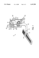
- FIG. 1 is a perspective view of the treadle assembly with a portion of the housing removed for illustrating the internal structural arrangement
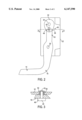
- FIG. 2 is a diagrammatic elevational view of the assembly
- FIG. 3 is a cross-sectional view, taken generally along the lines 3--3 of FIG. 2.
- the FIGURES show a treadle assembly A such as used in a heavy duty vehicle or truck having an electronically controlled engine. More specifically, the treadle assembly A includes a pedal or treadle 10 having a non-slip material such as plastic, rubber, or the like thereon. The treadle is pivotally mounted via pin 12 to a first end 14 of pedal lever or arm 16. In the illustrated embodiment, the lever has a generally L-shape. A second end 18 of the lever is disposed on an opposite side of a pivot pin 20 from the first end and the pivot pin secures the lever to housing 22.
- a biasing member such as a pair of springs 30a, 30b located on opposite sides of the lever and about the pivot pin 20, urges the lever to the position shown in FIG. 1.
- the second end 18 of the lever cooperates with a rotatable member or gear 32.
- the gear rotates about an axle 34 which passes through a sidewall of the housing 22.
- the gear includes a lobe 36 which accommodates a slot and pin assembly 40 that connects the gear to the lever second end. More particularly, in the preferred arrangement an elongated slot 42 is provided in the rotatable gear and the pin 44 extends from the lever second end (FIG. 2).
- a slot and pin assembly 40 that connects the gear to the lever second end.
- the pin 44 includes an enlarged shoulder 46 and a shaft portion 48 that extends through the slot 42.
- a roller bearing or similar bearing member 50 is interposed between the pin and the gear to minimize friction associated between the relatively moving components.
- a snap ring 52 is received adjacent one end of the pin to secure the slot and pin assembly together.
- the slot and pin connection effectively transfers the pivoting motion of the lever second end into rotational movement of the gear about its axle 34.
- the rotation of the axle 34 is input to a position sensor such as potentiometer 60 having a connection area 62 from which a lead extends for communicating an electrical output signal to the vehicle engine.
- the housing 22 is preferably secured to the operator compartment through a conventional bracket assembly 74, although it will be understood that still other mounting arrangements can be used without departing from the scope and intent of the present invention.
- the slot and pin connection transfers this motion into selective rotational movement of the gear 32.
- the slot and pin connection accommodates tolerance stackup concerns that are associated with other more precisely fit components.
- the slot and pin connection allows the components to be manufactured from stamp metal rather than employing a more expensive laser cut where a higher degree of precision of the components is required. No loss in function, however, results from the less expensive manufacturing process and structural arrangement.
- the assembly is also more forgiving of misalignment that may occur between the components so that tolerance stackup that is associated with more precisely fit components is less of a problem with the present invention.
- the treadle arm pivots and causes the gear to rotate.
- the gear rotates and provides an input to the potentiometer which sends a signal to the electronic controlled engine (not shown).
- the lever, gear, and potentiometer are all secured to the housing so that they properly interact with one another.
- the spring assembly urges the lever to the deactuated position, so that the treadle is disposed in a first or idle position as illustrated.
Abstract
A treadle assembly provides an electrical signal to an electronic controlled engine. The assembly includes a treadle suspended in the operator compartment. The treadle is pivotally mounted to a lever which pivots in response to the operator imposed depression of the treadle which, in turn, actuates a rotatable gear. The gear is in operative engagement with the potentiometer and an electrical signal is sent to the engine in response to rotation of the gear. The lever and gear are preferably interconnected by a slot and pin connection to reduce manufacturing costs associated with the components and accommodate misalignment during assembly and tolerance stackup associated with assembling individual components together.
Description
1. Field of the Invention
This invention pertains to the art of electronic control engines, and more particularly to providing an electrical input to the engine. The invention relates to an electronic treadle or pedal assembly that is simple to manufacture and assemble and is less expensive than known alternatives.
2. Background Art
Manufacturers continue to develop electronically controlled engines that are responsive to electrical signals associated with various operating parameters of the vehicle. One such parameter is the driver's desire for power that is input through depression of an accelerator pedal or treadle assembly located in the vehicle operator compartment. Depressing the treadle provides a suitable electronic signal to be sent to the electronic control unit (ECU) associated with the engine. For example, a potentiometer generates an electronic signal corresponding to the degree of depression of the treadle. One such commercially successful unit is shown and described in U.S. Pat. No. 4,528,590, the disclosure of which is commonly owned by the assignee of the present invention, and the details of which are incorporated herein by reference.
It has been proposed that mating components be used to transfer the force imposed by depression of a treadle to the input of a position sensor or rotary potentiometer. However, increasing the precision between the mating components increases the manufacturing costs and also increases the potential for wear. Accordingly, a need exists for a simplified design that achieves the same objectives, but at a decreased cost and that accommodates tolerance stackup conditions.
The present invention contemplates a new and improved treadle assembly for an electronic braking system that overcomes the above-referenced problems and others and provides a simple, economical assembly.
The treadle assembly includes a housing having a lever pivotally mounted thereto with a first end that engages a treadle and a second end engaging a rotatable member. The rotatable member is secured to the lever via a slot and pin assembly to simplify the manufacturing costs and alleviate misalignment concerns. A position sensor provides an output signal indicative of the movement of the rotatable member and, likewise, the degree of depression of the treadle.
The slot is elongated and extends generally radially on the rotatable member for receiving the pin extending from the lever.
A primary advantage of the invention is the ability to decrease the manufacturing costs associated with this design.
Yet another advantage of the invention resides in the minimal number of components of the assembly without any attendant loss in function.
Still another advantage of the invention is associated with the decreased sensitivity to misalignment.
Still other advantages and benefits of the invention will become apparent to those skilled in the art upon a reading and understanding of the following detailed description.
The invention may take physical form in various parts and arrangements of parts, a preferred embodiment of which is described in detail in this specification. A preferred arrangement of the invention is illustrated in the accompanying drawings, which include:
FIG. 1 is a perspective view of the treadle assembly with a portion of the housing removed for illustrating the internal structural arrangement;
FIG. 2 is a diagrammatic elevational view of the assembly; and
FIG. 3 is a cross-sectional view, taken generally along the lines 3--3 of FIG. 2.
Referring now to the drawings wherein the showings are for the purposes of illustrating the preferred embodiment of the invention only and not for limiting the invention, the FIGURES show a treadle assembly A such as used in a heavy duty vehicle or truck having an electronically controlled engine. More specifically, the treadle assembly A includes a pedal or treadle 10 having a non-slip material such as plastic, rubber, or the like thereon. The treadle is pivotally mounted via pin 12 to a first end 14 of pedal lever or arm 16. In the illustrated embodiment, the lever has a generally L-shape. A second end 18 of the lever is disposed on an opposite side of a pivot pin 20 from the first end and the pivot pin secures the lever to housing 22. A biasing member, such as a pair of springs 30a, 30b located on opposite sides of the lever and about the pivot pin 20, urges the lever to the position shown in FIG. 1.
The second end 18 of the lever cooperates with a rotatable member or gear 32. The gear rotates about an axle 34 which passes through a sidewall of the housing 22. The gear includes a lobe 36 which accommodates a slot and pin assembly 40 that connects the gear to the lever second end. More particularly, in the preferred arrangement an elongated slot 42 is provided in the rotatable gear and the pin 44 extends from the lever second end (FIG. 2). Of course it will be recognized by those skilled in the art that the locations of the slot and pin can be reversed without departing from the scope and intent of the subject invention.
As illustrated in FIG. 3, the pin 44 includes an enlarged shoulder 46 and a shaft portion 48 that extends through the slot 42. A roller bearing or similar bearing member 50 is interposed between the pin and the gear to minimize friction associated between the relatively moving components. In addition, a snap ring 52 is received adjacent one end of the pin to secure the slot and pin assembly together.
The slot and pin connection effectively transfers the pivoting motion of the lever second end into rotational movement of the gear about its axle 34. The rotation of the axle 34, in turn, is input to a position sensor such as potentiometer 60 having a connection area 62 from which a lead extends for communicating an electrical output signal to the vehicle engine.
The housing 22 is preferably secured to the operator compartment through a conventional bracket assembly 74, although it will be understood that still other mounting arrangements can be used without departing from the scope and intent of the present invention.
Pivotal movement of the treadle lever caused by depressing the treadle 10 urges the lever second end 18 to pivot about pin 20. The slot and pin connection transfers this motion into selective rotational movement of the gear 32. As will be appreciated, the slot and pin connection accommodates tolerance stackup concerns that are associated with other more precisely fit components. In this instance, the slot and pin connection allows the components to be manufactured from stamp metal rather than employing a more expensive laser cut where a higher degree of precision of the components is required. No loss in function, however, results from the less expensive manufacturing process and structural arrangement. The assembly is also more forgiving of misalignment that may occur between the components so that tolerance stackup that is associated with more precisely fit components is less of a problem with the present invention.
In operation, as the driver depresses the treadle, the treadle arm pivots and causes the gear to rotate. The gear rotates and provides an input to the potentiometer which sends a signal to the electronic controlled engine (not shown). The lever, gear, and potentiometer are all secured to the housing so that they properly interact with one another. The spring assembly urges the lever to the deactuated position, so that the treadle is disposed in a first or idle position as illustrated.
The invention has been described with reference to the preferred embodiment. Obviously, modifications and alterations will occur to others upon a reading and understanding of this specification. For example, the slot and pin connection can be reversed. Alternate materials of construction could also be used, or the design shape or configuration of the individual components may be altered. Likewise, a different type of biasing spring could also be used. It is intended that these modifications and alterations are included in the present specification in so far as they come within the scope of the appended claims or the equivalents thereof.
Claims (11)
1. A treadle assembly for an electronic motor vehicle system comprising:
a treadle adapted for selective depression by an operator's foot;
a lever operatively engaging the treadle adjacent a first end and having a second, output end, said lever including a pin at the second end of the lever;
a rotatable member located in operative relation to the output end of the lever having a closed-ended slot adapted to receive said pin such that translational movement of the lever causes the pin to slide in the slot and thereby transfer translational movement of the lever into selective rotation of the rotatable member; and
a position sensor operatively associated with the rotatable member for providing an output signal indicative of the degree of depression of the treadle.
2. The invention of claim 1 further comprising a housing and pivot member mounted thereto, the pivot member receiving an intermediate portion of the lever for mounting the lever for pivoting movement relative thereto.
3. The invention of claim 2 further comprising an axle secured to the housing and about which the rotatable member rotates, the position sensor mounted to the housing and receiving the axle therein.
4. The invention of claim 1 further comprising a biasing member urging the lever toward a deactuated position.
5. The invention of claim 1 further wherein the slot is provided on the rotatable member and extends radially from said rotatable member's axis of rotation.
6. The invention of claim 5 wherein the rotatable member includes a lobe having said slot formed therein.
7. The invention of claim 1 wherein the treadle is pivotally mounted to the first end of the lever.
8. A treadle assembly for supplying an electrical signal to an electronic control unit of a vehicle, the assembly comprising:
a housing;
a lever pivotally mounted to the housing and having a first end extending from the housing and a second end spaced from the first end, said lever including a pin at the second end of the lever;
a treadle secured to the lever first end and adapted for selective depression by a vehicle operator;
a gear assembly comprising a gear and an axle for securing the gear assembly to the housing, said gear including a closed-ended slot in said gear adapted to receive said pin such that translational movement of the lever causes the pin to slide in the slot and thereby transfer said translational movement of the lever into selective rotation of the gear assembly; and
a potentiometer receiving an end of the axle extending from the gear assembly to supply an electrical signal to the electronic control unit in response to depression of the treadle by the operator.
9. The invention of claim 8 further comprising a biasing spring interposed between the housing and the lever for urging the treadle toward the deactuated position.
10. The invention of claim 8 wherein the gear assembly includes the slot therein extending in a radial direction from the axle and pin on the second end of the lever.
11. The invention of claim 8 wherein the slot is elongated and extends radially from the axle in a lobe portion the gear.
Priority Applications (1)
| Application Number | Priority Date | Filing Date | Title |
|---|---|---|---|
| US09/393,539 US6147590A (en) | 1999-09-10 | 1999-09-10 | Electronic treadle linkage assembly |
Applications Claiming Priority (1)
| Application Number | Priority Date | Filing Date | Title |
|---|---|---|---|
| US09/393,539 US6147590A (en) | 1999-09-10 | 1999-09-10 | Electronic treadle linkage assembly |
Publications (1)
| Publication Number | Publication Date |
|---|---|
| US6147590A true US6147590A (en) | 2000-11-14 |
Family
ID=23555122
Family Applications (1)
| Application Number | Title | Priority Date | Filing Date |
|---|---|---|---|
| US09/393,539 Expired - Fee Related US6147590A (en) | 1999-09-10 | 1999-09-10 | Electronic treadle linkage assembly |
Country Status (1)
| Country | Link |
|---|---|
| US (1) | US6147590A (en) |
Cited By (8)
| Publication number | Priority date | Publication date | Assignee | Title |
|---|---|---|---|---|
| US20030051571A1 (en) * | 1999-10-29 | 2003-03-20 | Staker William C. | Electronic control pedal and position sensing device and assembly method |
| US6718845B2 (en) * | 2001-10-09 | 2004-04-13 | Teleflex Incorporated | Pedal assembly with radially overlying sensor and hysteresis |
| US6725741B2 (en) * | 2001-10-09 | 2004-04-27 | Teleflex Incorporated | Compact pedal assembly with electrical sensor arm pivotal about axis spaced from pedal axis |
| US20080141820A1 (en) * | 2006-12-14 | 2008-06-19 | Hangil Park | Accelerator pedal system |
| US20080202279A1 (en) * | 2005-06-17 | 2008-08-28 | Andree Burgstaler | Pedal Arrangement for a Motor Vehilce |
| US20110035039A1 (en) * | 2008-06-30 | 2011-02-10 | Bombardier Recreational Products Inc. | Lever position sensor |
| US20110083527A1 (en) * | 2009-09-24 | 2011-04-14 | Mikuni Corporation | Accelerator pedal apparatus |
| JP2020100174A (en) * | 2018-12-20 | 2020-07-02 | 株式会社デンソー | Accelerating device |
Citations (12)
| Publication number | Priority date | Publication date | Assignee | Title |
|---|---|---|---|---|
| US792241A (en) * | 1905-02-13 | 1905-06-13 | Sturtevant Mill Co | Controlling device for motor-vehicles. |
| US1438288A (en) * | 1920-09-21 | 1922-12-12 | Barbarou Marius Jean Baptiste | Pedal device for motor vehicles |
| US1990447A (en) * | 1930-01-16 | 1935-02-05 | Bendix Brake Co | Variable resistor |
| US2379774A (en) * | 1943-01-02 | 1945-07-03 | Gen Electric | Control apparatus |
| US4528590A (en) * | 1983-11-09 | 1985-07-09 | Allied Corporation | Electronic treadle |
| US4958607A (en) * | 1989-04-18 | 1990-09-25 | Williams Controls, Inc. | Foot pedal arrangement for electronic throttle control of truck engines |
| US5063811A (en) * | 1990-07-09 | 1991-11-12 | Ford Motor Company | Accelerator pedal assembly |
| US5241936A (en) * | 1991-09-09 | 1993-09-07 | Williams Controls, Inc. | Foot pedal arrangement for electronic throttle control of truck engines |
| US5408899A (en) * | 1993-06-14 | 1995-04-25 | Brecom Subsidiary Corporation No. 1 | Foot pedal devices for controlling engines |
| US5507201A (en) * | 1994-09-30 | 1996-04-16 | Ford Motor Company | Accelerator assembly for automotive vehicle |
| US5693927A (en) * | 1996-01-25 | 1997-12-02 | Wilson; Dallas W. | Vehicle accelerator pedal switch actuator |
| US5768946A (en) * | 1994-10-11 | 1998-06-23 | Cts Corporation | Pedal with integrated position sensor |
-
1999
- 1999-09-10 US US09/393,539 patent/US6147590A/en not_active Expired - Fee Related
Patent Citations (12)
| Publication number | Priority date | Publication date | Assignee | Title |
|---|---|---|---|---|
| US792241A (en) * | 1905-02-13 | 1905-06-13 | Sturtevant Mill Co | Controlling device for motor-vehicles. |
| US1438288A (en) * | 1920-09-21 | 1922-12-12 | Barbarou Marius Jean Baptiste | Pedal device for motor vehicles |
| US1990447A (en) * | 1930-01-16 | 1935-02-05 | Bendix Brake Co | Variable resistor |
| US2379774A (en) * | 1943-01-02 | 1945-07-03 | Gen Electric | Control apparatus |
| US4528590A (en) * | 1983-11-09 | 1985-07-09 | Allied Corporation | Electronic treadle |
| US4958607A (en) * | 1989-04-18 | 1990-09-25 | Williams Controls, Inc. | Foot pedal arrangement for electronic throttle control of truck engines |
| US5063811A (en) * | 1990-07-09 | 1991-11-12 | Ford Motor Company | Accelerator pedal assembly |
| US5241936A (en) * | 1991-09-09 | 1993-09-07 | Williams Controls, Inc. | Foot pedal arrangement for electronic throttle control of truck engines |
| US5408899A (en) * | 1993-06-14 | 1995-04-25 | Brecom Subsidiary Corporation No. 1 | Foot pedal devices for controlling engines |
| US5507201A (en) * | 1994-09-30 | 1996-04-16 | Ford Motor Company | Accelerator assembly for automotive vehicle |
| US5768946A (en) * | 1994-10-11 | 1998-06-23 | Cts Corporation | Pedal with integrated position sensor |
| US5693927A (en) * | 1996-01-25 | 1997-12-02 | Wilson; Dallas W. | Vehicle accelerator pedal switch actuator |
Cited By (12)
| Publication number | Priority date | Publication date | Assignee | Title |
|---|---|---|---|---|
| US20030051571A1 (en) * | 1999-10-29 | 2003-03-20 | Staker William C. | Electronic control pedal and position sensing device and assembly method |
| US6802113B2 (en) * | 1999-10-29 | 2004-10-12 | William C. Staker | Electronic control pedal position sensing device assembly method |
| US6718845B2 (en) * | 2001-10-09 | 2004-04-13 | Teleflex Incorporated | Pedal assembly with radially overlying sensor and hysteresis |
| US6725741B2 (en) * | 2001-10-09 | 2004-04-27 | Teleflex Incorporated | Compact pedal assembly with electrical sensor arm pivotal about axis spaced from pedal axis |
| US20080202279A1 (en) * | 2005-06-17 | 2008-08-28 | Andree Burgstaler | Pedal Arrangement for a Motor Vehilce |
| US20080141820A1 (en) * | 2006-12-14 | 2008-06-19 | Hangil Park | Accelerator pedal system |
| US7784377B2 (en) * | 2006-12-14 | 2010-08-31 | Hyundai Motor Company | Accelerator pedal system |
| US20110035039A1 (en) * | 2008-06-30 | 2011-02-10 | Bombardier Recreational Products Inc. | Lever position sensor |
| US8491348B2 (en) * | 2008-06-30 | 2013-07-23 | Bombardier Recreational Products Inc. | Lever position sensor |
| US20110083527A1 (en) * | 2009-09-24 | 2011-04-14 | Mikuni Corporation | Accelerator pedal apparatus |
| US8794103B2 (en) * | 2009-09-24 | 2014-08-05 | Mikuni Corporation | Accelerator pedal apparatus |
| JP2020100174A (en) * | 2018-12-20 | 2020-07-02 | 株式会社デンソー | Accelerating device |
Similar Documents
| Publication | Publication Date | Title |
|---|---|---|
| US4958607A (en) | Foot pedal arrangement for electronic throttle control of truck engines | |
| US4528590A (en) | Electronic treadle | |
| US5416295A (en) | Combined pedal force switch and position sensor | |
| US5768946A (en) | Pedal with integrated position sensor | |
| US5385068A (en) | Electronic accelerator pedal assembly with pedal force sensor | |
| US5241936A (en) | Foot pedal arrangement for electronic throttle control of truck engines | |
| EP0702749B1 (en) | Foot pedal devices for controlling engines | |
| US5507201A (en) | Accelerator assembly for automotive vehicle | |
| US20100077886A1 (en) | Accelerator Pedal for a Vehicle | |
| WO2010096164A1 (en) | Accelerator pedal for a vehicle | |
| US20050155809A1 (en) | Mechanical clutch coupling back-up for electric steering system | |
| US6147590A (en) | Electronic treadle linkage assembly | |
| US10551866B2 (en) | Pedal assembly with debris filtering mechanism | |
| JPH04224242A (en) | Throttle control device | |
| EP0548945B1 (en) | Throttle control apparatus | |
| EP1128976A1 (en) | Electronic treadle gear design | |
| JPH04224241A (en) | Throttle control device | |
| JP3436512B2 (en) | Accelerator device | |
| US6155133A (en) | Electronic treadle four bar assembly | |
| WO1995007199A1 (en) | Variable pressure windshield wiper arm | |
| JP2877600B2 (en) | Throttle control device | |
| US20010035508A1 (en) | Return spring and adjusting mechanism for an automotive throttle body | |
| US6003492A (en) | Throttle control apparatus | |
| JP2902193B2 (en) | Throttle control device | |
| JP3006250B2 (en) | Throttle control device |
Legal Events
| Date | Code | Title | Description |
|---|---|---|---|
| AS | Assignment |
Owner name: ALLIEDSIGNAL TRUCK BRAKE SYSTEMS CO., OHIO Free format text: ASSIGNMENT OF ASSIGNORS INTEREST;ASSIGNOR:MIKOLCIC, ALLEN;REEL/FRAME:010239/0629 Effective date: 19990809 |
|
| FPAY | Fee payment |
Year of fee payment: 4 |
|
| REMI | Maintenance fee reminder mailed | ||
| LAPS | Lapse for failure to pay maintenance fees | ||
| STCH | Information on status: patent discontinuation |
Free format text: PATENT EXPIRED DUE TO NONPAYMENT OF MAINTENANCE FEES UNDER 37 CFR 1.362 |
|
| FP | Expired due to failure to pay maintenance fee |
Effective date: 20081114 |