US6314831B2 - Adjustable pedal-parallel screw and rod - Google Patents
Adjustable pedal-parallel screw and rod Download PDFInfo
- Publication number
- US6314831B2 US6314831B2 US09/379,778 US37977899A US6314831B2 US 6314831 B2 US6314831 B2 US 6314831B2 US 37977899 A US37977899 A US 37977899A US 6314831 B2 US6314831 B2 US 6314831B2
- Authority
- US
- United States
- Prior art keywords
- pedal
- guide rod
- assembly
- bracket
- screw
- Prior art date
- Legal status (The legal status is an assumption and is not a legal conclusion. Google has not performed a legal analysis and makes no representation as to the accuracy of the status listed.)
- Expired - Fee Related
Links
Images


Classifications
-
- B—PERFORMING OPERATIONS; TRANSPORTING
- B60—VEHICLES IN GENERAL
- B60K—ARRANGEMENT OR MOUNTING OF PROPULSION UNITS OR OF TRANSMISSIONS IN VEHICLES; ARRANGEMENT OR MOUNTING OF PLURAL DIVERSE PRIME-MOVERS IN VEHICLES; AUXILIARY DRIVES FOR VEHICLES; INSTRUMENTATION OR DASHBOARDS FOR VEHICLES; ARRANGEMENTS IN CONNECTION WITH COOLING, AIR INTAKE, GAS EXHAUST OR FUEL SUPPLY OF PROPULSION UNITS IN VEHICLES
- B60K26/00—Arrangements or mounting of propulsion unit control devices in vehicles
-
- G—PHYSICS
- G05—CONTROLLING; REGULATING
- G05G—CONTROL DEVICES OR SYSTEMS INSOFAR AS CHARACTERISED BY MECHANICAL FEATURES ONLY
- G05G1/00—Controlling members, e.g. knobs or handles; Assemblies or arrangements thereof; Indicating position of controlling members
- G05G1/30—Controlling members actuated by foot
- G05G1/40—Controlling members actuated by foot adjustable
- G05G1/405—Controlling members actuated by foot adjustable infinitely adjustable
-
- Y—GENERAL TAGGING OF NEW TECHNOLOGICAL DEVELOPMENTS; GENERAL TAGGING OF CROSS-SECTIONAL TECHNOLOGIES SPANNING OVER SEVERAL SECTIONS OF THE IPC; TECHNICAL SUBJECTS COVERED BY FORMER USPC CROSS-REFERENCE ART COLLECTIONS [XRACs] AND DIGESTS
- Y10—TECHNICAL SUBJECTS COVERED BY FORMER USPC
- Y10T—TECHNICAL SUBJECTS COVERED BY FORMER US CLASSIFICATION
- Y10T74/00—Machine element or mechanism
- Y10T74/20—Control lever and linkage systems
- Y10T74/20528—Foot operated
-
- Y—GENERAL TAGGING OF NEW TECHNOLOGICAL DEVELOPMENTS; GENERAL TAGGING OF CROSS-SECTIONAL TECHNOLOGIES SPANNING OVER SEVERAL SECTIONS OF THE IPC; TECHNICAL SUBJECTS COVERED BY FORMER USPC CROSS-REFERENCE ART COLLECTIONS [XRACs] AND DIGESTS
- Y10—TECHNICAL SUBJECTS COVERED BY FORMER USPC
- Y10T—TECHNICAL SUBJECTS COVERED BY FORMER US CLASSIFICATION
- Y10T74/00—Machine element or mechanism
- Y10T74/20—Control lever and linkage systems
- Y10T74/20576—Elements
- Y10T74/20888—Pedals
Definitions
- the subject invention relates to an adjustable pedal assembly of the type attached to an automotive vehicle to control the brake, clutch and/or throttle in normal operation but which can be adjusted to a different position to accommodate a different driver position.
- Foot operated pedals are provided for controlling the brakes, clutch, and engine throttle in automotive vehicles.
- Pedal assemblies have been recently developed wherein the position of pedal can be adjusted to accommodate different operators and/or driving positions.
- One group of such assemblies include a guide rod slidably supporting a pedal support with a pedal lever mounted on the support.
- a screw is included for driving the pedal support along the rod between various adjusted positions.
- the screw is disposed within the guide rod which complicates the drive connection between the pedal support and the screw. Variations of such assemblies are disclosed in U.S. Pat. Nos. 3,643,525; 4,875,385; 4,989,474; 5,078,024; 5,460,061; 5,697,260; 5,722,302 and 5,819,593.
- An adjustable pedal assembly comprising a guide rod, a pedal support slidably supported on the guide rod, a pedal pivotally mounted on the support, and a screw for driving said pedal support along the rod.
- the assembly is characterized by the screw being external to and parallel to the guide rod.
- the combination of he subject invention reduces the number of components, the combined weight and the manufacturing operations. In a more specific sense, there is no need to bore out the center of the guide rod to insert the screw when the screw is located external to and parallel to the guide rod. This feature allows for a solid guide rod to be used, saving money and time in manufacturing the product.
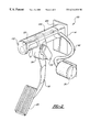
- FIG. 1 is a perspective view of a first embodiment
- FIG. 2 is a perspective view of a second embodiment
- FIG. 3 is a perspective view of a third embodiment.
- an embodiment of an adjustable pedal assembly constructed in accordance with the subject invention is generally shown at 10 , 110 and 210 , respectively, in FIGS. 1, 2 and 3 , respectively.
- Each adjustable pedal assembly 10 , 110 and 210 includes a guide rod 12 .
- the guide rod 12 in the embodiment of FIGS. 1 and 3 is D-shaped as viewed in cross section to provide a key or flat surface 13 .
- a bracket 14 or 214 is adapted for attachment to the structure of a motor vehicle and the guide rod 12 is fixed to and extends from the bracket 14 or 214 .
- a pedal support 16 , 116 or 216 is slidably supported on the guide rod 12 .
- a pedal lever 18 , 118 or 218 is mounted on the support 16 , 116 or 216 and includes a pedal pad 20 at its lower distal end.
- a screw 22 extends from the bracket 14 or 214 for driving the pedal support 16 , 116 or 216 along the guide rod 12 .
- the screw 22 threadedly engages the support 16 , 116 or 216 whereby the support 16 , 116 or 216 moves along the guide rod 12 in response to rotation of the screw 22 .
- a drive mechanism 24 , 124 or 224 for rotating the screw 22 comprises a gear box which may be driven by an electric motor 26 . In the embodiment of FIGS.
- the drive mechanism 24 or 124 is disposed on the guide rod 12 adjacent the bracket 14 , i.e., the drive mechanism 24 or 124 is secured to both the guide rod 12 and the bracket 14 .
- the bracket 214 is defined by a housing and the drive mechanism 224 is disposed in the housing of the bracket 214 , (the motor not being shown in FIG. 3 ).
- the adjustable pedal assemblies 10 , 110 and 210 are characterized by the screw 22 being external to and parallel to the guide rod 12 .
- the pedal lever 18 or 118 is pivotally attached to the support 16 or 116 .
- a pin such as that shown at 28 in FIG. 1 secures the pedal levers 18 and 118 to the respective supports 16 and 116 .
- a torsion spring 30 surrounds the pin 28 to react with the pedal levers 18 and 118 to provide a resistance to pivotal movement thereof. It is important to use a pedal assembly which provides for a hysteresis effect to allow an operator advancing a pedal using foot pressure to have to use greater pressure for pedal advancement than that required to maintain a fixed position.
- the hysteresis effect lessens the load to maintain a setting of the pedal, yet there is still enough force to cause reverse pedal action when a foot applied pressure is removed.
- the torsion spring 30 provides such a hysteresis effect.
- an electrical signal generator 32 or 132 is supported by each of the pedal supports 16 and 116 for generating an electrical signal, which, in turn, controls the brake system or throttle.
- the bracket 214 of the embodiment of FIG. 3 includes a connection 36 for rotatably supporting the bracket 214 on a vehicle in response to pivotal movement of the pedal lever.
- a pin 36 rotatably supports the bracket 214 on the vehicle structure 38 .
- the pedal lever 218 and the support 216 are defined by an integral or one piece plastic member which threadedly engages the screw 22 and is in sliding engagement with the guide rod 12 .
- the integral one piece member extends downwardly from the guide rod 12 to a pedal pad 20 end.
- the top end of the integral one piece member includes an element connector 40 adapted for connection to an element to be controlled, such as a cable assembly leading to the brake system or throttle.
- the screw 22 and the guide rod 12 extend from the brackets 14 , 114 and 214 to distal ends. These distal ends are cantilevered or unconnected in the embodiment of FIG. 1 whereas a cap 142 or 242 interconnects the distal ends in the embodiments of FIGS. 2 and 3.
- the cap 142 is integral with a cover 144 which extends between the cap 142 and the drive mechanism 124 or bracket 14 .
- the caps 142 and 242 are secured to the distal ends of the screw 22 and the guide rod 12 to maintain stability and the parallel relationship between the screw 22 and the guide rod 12 .
- the guide rod 12 extends rigidly rearward from the bracket 14 or 214 and is made of any standard metal.
- the guide rod 12 can attach either directly to the bracket 14 , 114 or 214 or to the drive mechanism 24 , 124 or 224 which is fixedly attached to the bracket 14 , 114 or 214 .
- the guide rod 12 could be slotted at either end to facilitate attachment to the bracket 14 , 114 or 214 or to the bearing caps 142 or 242 .
- the pedal support 16 , 116 or 216 which may be formed as a casting, forging or stamping, and is designed to move slidably along the guide rod 12 .
- the one piece member defining the pedal lever 218 and the support 216 is molded of an organic polymeric material, which significantly reduces weight.
- the drive mechanism 24 , 124 or 224 may be attached to a motor 26 which can be located at any position within the front of the car so long as a connection 46 can be made to the drive mechanism 24 , 124 or 224 .
- the motor can be any standard motor which can be activated by an electric signal generated by an operator.
- the use of the potentiometer as a signal generator 32 or 132 is an effective manner of generating a signal and such is disclosed in U.S. Pat. No. 5,819,593 which is assigned of the present invention.
- the signal generator 32 or 132 responds to pedal lever 18 , 118 or 218 movement by generating a signal which is used by a corresponding device, such as the vehicle computer and/or the engine controller.
Abstract
Description
Claims (11)
Priority Applications (5)
| Application Number | Priority Date | Filing Date | Title |
|---|---|---|---|
| US09/379,778 US6314831B2 (en) | 1999-08-24 | 1999-08-24 | Adjustable pedal-parallel screw and rod |
| EP00202613A EP1083472A1 (en) | 1999-08-24 | 2000-07-20 | Adjustable pedal-parallel screw and rod |
| KR10-2000-0043851A KR100395738B1 (en) | 1999-08-24 | 2000-07-28 | Adjustable pedal-parallel screw and rod |
| MXPA00008025A MXPA00008025A (en) | 1999-08-24 | 2000-08-17 | Adjustable pedal-parallel screw and rod. |
| JP2000250789A JP2001109533A (en) | 1999-08-24 | 2000-08-22 | Adjustable pedal-parallel screw and rod |
Applications Claiming Priority (1)
| Application Number | Priority Date | Filing Date | Title |
|---|---|---|---|
| US09/379,778 US6314831B2 (en) | 1999-08-24 | 1999-08-24 | Adjustable pedal-parallel screw and rod |
Publications (2)
| Publication Number | Publication Date |
|---|---|
| US20010002556A1 US20010002556A1 (en) | 2001-06-07 |
| US6314831B2 true US6314831B2 (en) | 2001-11-13 |
Family
ID=23498648
Family Applications (1)
| Application Number | Title | Priority Date | Filing Date |
|---|---|---|---|
| US09/379,778 Expired - Fee Related US6314831B2 (en) | 1999-08-24 | 1999-08-24 | Adjustable pedal-parallel screw and rod |
Country Status (5)
| Country | Link |
|---|---|
| US (1) | US6314831B2 (en) |
| EP (1) | EP1083472A1 (en) |
| JP (1) | JP2001109533A (en) |
| KR (1) | KR100395738B1 (en) |
| MX (1) | MXPA00008025A (en) |
Cited By (6)
| Publication number | Priority date | Publication date | Assignee | Title |
|---|---|---|---|---|
| US20030164058A1 (en) * | 2001-02-19 | 2003-09-04 | Franck Sauvonnet | Brake pedal designed to equip a motor vehicle |
| US6629472B2 (en) * | 2000-01-27 | 2003-10-07 | United Parts Fhs Automobil Systeme Gmbh | Adjustable pedal for vehicles |
| US6834904B2 (en) * | 2001-02-19 | 2004-12-28 | Peugeot Citroën Automobiles SA | Footrest for motor vehicle |
| US20050166702A1 (en) * | 2004-02-03 | 2005-08-04 | Christopher Rixon | Adjustable pedal assembly with step-over control |
| US7014022B2 (en) | 2001-02-19 | 2006-03-21 | Peugeot Citroën Automobiles SA | Clutch pedal designed to equip a motor vehicle |
| US9163707B2 (en) | 2011-09-30 | 2015-10-20 | Mtd Products Inc | Method for controlling the speed of a self-propelled walk-behind lawn mower |
Families Citing this family (9)
| Publication number | Priority date | Publication date | Assignee | Title |
|---|---|---|---|---|
| US6205883B1 (en) * | 1999-09-30 | 2001-03-27 | Teleflex Incorporated | Adjustable pedal-pocketed gears |
| US6564672B2 (en) | 2000-05-15 | 2003-05-20 | Grand Haven Stamped Products, Division Of Jsj Corporation | Adjustable pedal apparatus |
| US6619155B2 (en) | 2000-05-15 | 2003-09-16 | Grand Haven Stamped Products, Division Of Jsj Corporation | Adjustable pedal apparatus |
| SI22428A (en) * | 2006-12-27 | 2008-06-30 | Cimos D.D. | Pedal mechanism of a motor vehicle |
| KR101241567B1 (en) * | 2010-11-26 | 2013-03-11 | 주식회사 동희산업 | Sensuous pedal for vehicle |
| KR101316439B1 (en) | 2010-11-30 | 2013-10-08 | 주식회사 동희산업 | Organ type accelerator pedal device in vehicle |
| KR101407386B1 (en) * | 2012-04-24 | 2014-06-27 | 계명대학교 산학협력단 | position adjustable pedal assembly for automobiles |
| KR101619659B1 (en) | 2014-12-08 | 2016-05-10 | 현대자동차주식회사 | Brake pedal apparatus |
| CN112172680A (en) * | 2020-09-24 | 2021-01-05 | 敖家明 | Automobile pedal |
Citations (20)
| Publication number | Priority date | Publication date | Assignee | Title |
|---|---|---|---|---|
| GB920784A (en) * | 1960-08-17 | 1963-03-13 | Standard Pressed Steel Co | Improvements in or relating to control pedals for vehicles |
| US3288239A (en) * | 1964-05-25 | 1966-11-29 | Gen Motors Corp | Adjustable toeboard and control pedal for vehicles |
| US3359821A (en) | 1965-10-11 | 1967-12-26 | Lockheed Aircraft Corp | Connecting mechanism between a control lever and multiple controlled members |
| US3643525A (en) * | 1970-05-26 | 1972-02-22 | Gen Motors Corp | Adjustable control pedals for vehicles |
| US3643524A (en) * | 1970-05-26 | 1972-02-22 | Gen Motors Corp | Control pedals for vehicles |
| US4312246A (en) * | 1979-12-26 | 1982-01-26 | Barresi Zina V | Dual operating system for controlling a brake or the like, including a counter system to prevent or reverse operation |
| JPS5967145A (en) * | 1982-10-06 | 1984-04-16 | Toyota Tekko Kk | Pedal type parking brake operating device |
| JPS6111836A (en) * | 1984-06-26 | 1986-01-20 | Mazda Motor Corp | Pedal device of automoble |
| US4870871A (en) * | 1987-05-22 | 1989-10-03 | Wickes Manufacturing Company | Adjustable accelerator and brake pedal mechanism |
| US4875385A (en) * | 1986-08-18 | 1989-10-24 | Sitrin Gabriel M | Control pedal apparatus for a motor vehicle |
| US4903936A (en) | 1987-09-22 | 1990-02-27 | Mitsubishi Denki Kabushiki Kaisha | Throttle valve actuator including separate valve driving devices |
| JPH02116911A (en) * | 1988-10-26 | 1990-05-01 | Fuji Kiko Co Ltd | Forward/backward adjustable stepping type pedal |
| US4989474A (en) | 1986-08-18 | 1991-02-05 | Brecom Corporation | Control pedal apparatus for a motor vehicle |
| US5078024A (en) | 1986-08-18 | 1992-01-07 | Comfort Pedals Inc. | Control pedal apparatus for a motor vehicle |
| US5460061A (en) | 1993-09-17 | 1995-10-24 | Comfort Pedals, Inc. | Adjustable control pedal apparatus |
| US5697260A (en) | 1995-08-09 | 1997-12-16 | Teleflex Incorporated | Electronic adjustable pedal assembly |
| US5722302A (en) | 1995-08-09 | 1998-03-03 | Teleflex, Inc. | Adjustable pedal assembly |
| US5819593A (en) | 1995-08-09 | 1998-10-13 | Comcorp Technologies, Inc. | Electronic adjustable pedal assembly |
| US5996438A (en) * | 1998-06-23 | 1999-12-07 | General Motors Corporation | Adjustable accelerator pedal |
| US6151985A (en) * | 1999-04-01 | 2000-11-28 | Daimlerchrysler Corporation | Adjustable pedal apparatus |
Family Cites Families (1)
| Publication number | Priority date | Publication date | Assignee | Title |
|---|---|---|---|---|
| US3754480A (en) * | 1972-05-08 | 1973-08-28 | Gen Motors Corp | Vehicle control apparatus |
-
1999
- 1999-08-24 US US09/379,778 patent/US6314831B2/en not_active Expired - Fee Related
-
2000
- 2000-07-20 EP EP00202613A patent/EP1083472A1/en not_active Withdrawn
- 2000-07-28 KR KR10-2000-0043851A patent/KR100395738B1/en not_active IP Right Cessation
- 2000-08-17 MX MXPA00008025A patent/MXPA00008025A/en unknown
- 2000-08-22 JP JP2000250789A patent/JP2001109533A/en active Pending
Patent Citations (20)
| Publication number | Priority date | Publication date | Assignee | Title |
|---|---|---|---|---|
| GB920784A (en) * | 1960-08-17 | 1963-03-13 | Standard Pressed Steel Co | Improvements in or relating to control pedals for vehicles |
| US3288239A (en) * | 1964-05-25 | 1966-11-29 | Gen Motors Corp | Adjustable toeboard and control pedal for vehicles |
| US3359821A (en) | 1965-10-11 | 1967-12-26 | Lockheed Aircraft Corp | Connecting mechanism between a control lever and multiple controlled members |
| US3643525A (en) * | 1970-05-26 | 1972-02-22 | Gen Motors Corp | Adjustable control pedals for vehicles |
| US3643524A (en) * | 1970-05-26 | 1972-02-22 | Gen Motors Corp | Control pedals for vehicles |
| US4312246A (en) * | 1979-12-26 | 1982-01-26 | Barresi Zina V | Dual operating system for controlling a brake or the like, including a counter system to prevent or reverse operation |
| JPS5967145A (en) * | 1982-10-06 | 1984-04-16 | Toyota Tekko Kk | Pedal type parking brake operating device |
| JPS6111836A (en) * | 1984-06-26 | 1986-01-20 | Mazda Motor Corp | Pedal device of automoble |
| US4989474A (en) | 1986-08-18 | 1991-02-05 | Brecom Corporation | Control pedal apparatus for a motor vehicle |
| US4875385A (en) * | 1986-08-18 | 1989-10-24 | Sitrin Gabriel M | Control pedal apparatus for a motor vehicle |
| US5078024A (en) | 1986-08-18 | 1992-01-07 | Comfort Pedals Inc. | Control pedal apparatus for a motor vehicle |
| US4870871A (en) * | 1987-05-22 | 1989-10-03 | Wickes Manufacturing Company | Adjustable accelerator and brake pedal mechanism |
| US4903936A (en) | 1987-09-22 | 1990-02-27 | Mitsubishi Denki Kabushiki Kaisha | Throttle valve actuator including separate valve driving devices |
| JPH02116911A (en) * | 1988-10-26 | 1990-05-01 | Fuji Kiko Co Ltd | Forward/backward adjustable stepping type pedal |
| US5460061A (en) | 1993-09-17 | 1995-10-24 | Comfort Pedals, Inc. | Adjustable control pedal apparatus |
| US5697260A (en) | 1995-08-09 | 1997-12-16 | Teleflex Incorporated | Electronic adjustable pedal assembly |
| US5722302A (en) | 1995-08-09 | 1998-03-03 | Teleflex, Inc. | Adjustable pedal assembly |
| US5819593A (en) | 1995-08-09 | 1998-10-13 | Comcorp Technologies, Inc. | Electronic adjustable pedal assembly |
| US5996438A (en) * | 1998-06-23 | 1999-12-07 | General Motors Corporation | Adjustable accelerator pedal |
| US6151985A (en) * | 1999-04-01 | 2000-11-28 | Daimlerchrysler Corporation | Adjustable pedal apparatus |
Cited By (10)
| Publication number | Priority date | Publication date | Assignee | Title |
|---|---|---|---|---|
| US6629472B2 (en) * | 2000-01-27 | 2003-10-07 | United Parts Fhs Automobil Systeme Gmbh | Adjustable pedal for vehicles |
| US20030164058A1 (en) * | 2001-02-19 | 2003-09-04 | Franck Sauvonnet | Brake pedal designed to equip a motor vehicle |
| US6834904B2 (en) * | 2001-02-19 | 2004-12-28 | Peugeot Citroën Automobiles SA | Footrest for motor vehicle |
| US7014022B2 (en) | 2001-02-19 | 2006-03-21 | Peugeot Citroën Automobiles SA | Clutch pedal designed to equip a motor vehicle |
| US7066048B2 (en) | 2001-02-19 | 2006-06-27 | Peugeot Citroën Automobiles SA | Brake pedal designed to equip a motor vehicle |
| US20050166702A1 (en) * | 2004-02-03 | 2005-08-04 | Christopher Rixon | Adjustable pedal assembly with step-over control |
| US7270028B2 (en) | 2004-02-03 | 2007-09-18 | Drivesol Worldwide, Inc. | Adjustable pedal assembly with step-over control |
| US9163707B2 (en) | 2011-09-30 | 2015-10-20 | Mtd Products Inc | Method for controlling the speed of a self-propelled walk-behind lawn mower |
| US9651138B2 (en) | 2011-09-30 | 2017-05-16 | Mtd Products Inc. | Speed control assembly for a self-propelled walk-behind lawn mower |
| US9791037B2 (en) | 2011-09-30 | 2017-10-17 | Mtd Products Inc | Speed control assembly for a self-propelled walk-behind lawn mower |
Also Published As
| Publication number | Publication date |
|---|---|
| JP2001109533A (en) | 2001-04-20 |
| KR100395738B1 (en) | 2003-08-25 |
| US20010002556A1 (en) | 2001-06-07 |
| EP1083472A1 (en) | 2001-03-14 |
| MXPA00008025A (en) | 2002-05-23 |
| KR20010021152A (en) | 2001-03-15 |
Similar Documents
| Publication | Publication Date | Title |
|---|---|---|
| US6314831B2 (en) | Adjustable pedal-parallel screw and rod | |
| US6298745B1 (en) | Adjustable pedal assembly | |
| KR100594958B1 (en) | Adjustable vehicle control pedals | |
| US6918316B2 (en) | Adjustable pedal assembly | |
| KR0161705B1 (en) | Adjustable automobile pedal system | |
| US5086663A (en) | Adjustable pedal | |
| US6758115B2 (en) | Adjustable brake, clutch and accelerator pedals | |
| US6584871B2 (en) | Adjustable pedal assembly | |
| US6367348B1 (en) | Adjustable brake, clutch and accelerator pedals | |
| US5884532A (en) | Adjustable pedal apparatus | |
| US6289761B1 (en) | Automatic adjustable brake, clutch and accelerator pedals | |
| US20040045393A1 (en) | Electronic throttle control hysteresis mechanism | |
| EP1220072A1 (en) | Adjustable pedal mechanism with mechanical active lock-up | |
| US6389927B1 (en) | Adjustable control vehicle pedal | |
| US2724285A (en) | Apparatus for operating pedal controls of an automobile | |
| US6609438B1 (en) | Electric adjustable pedal system with two-piece upper arm | |
| AU1638900A (en) | Adjustable automobile pedal system | |
| US6209417B1 (en) | Adjustable pedal with constant ratio cable assembly | |
| EP1280034A1 (en) | Device for adjusting the position of a pedal | |
| US7066048B2 (en) | Brake pedal designed to equip a motor vehicle | |
| EP1343065B1 (en) | Device to adjust the position of pedals in a motor-vehicle | |
| KR19990026034U (en) | Spacing device of clutch pedal for automobile | |
| MXPA98003293A (en) | Regula pedal apparatus |
Legal Events
| Date | Code | Title | Description |
|---|---|---|---|
| AS | Assignment |
Owner name: TELEFLEX INCORPORATED, PENNSYLVANIA Free format text: ASSIGNMENT OF ASSIGNORS INTEREST;ASSIGNORS:RIXON, CHRISTOPHER J.;BORTOLON, CHRISTOPHER;REEL/FRAME:010196/0533 Effective date: 19990805 |
|
| AS | Assignment |
Owner name: TECHNOLOGY HOLDING COMPANY, DELAWARE Free format text: ASSIGNMENT OF ASSIGNORS INTEREST;ASSIGNOR:TELEFLEX INCORPORATED;REEL/FRAME:014499/0075 Effective date: 20030902 |
|
| RF | Reissue application filed |
Effective date: 20031113 |
|
| REMI | Maintenance fee reminder mailed | ||
| AS | Assignment |
Owner name: WELLS FARGO FOOTHILL, INC., AS AGENT, GEORGIA Free format text: SECURITY AGREEMENT;ASSIGNOR:DRIVESOL WORLDWIDE, INC.;REEL/FRAME:016769/0421 Effective date: 20051108 |
|
| LAPS | Lapse for failure to pay maintenance fees | ||
| STCH | Information on status: patent discontinuation |
Free format text: PATENT EXPIRED DUE TO NONPAYMENT OF MAINTENANCE FEES UNDER 37 CFR 1.362 |
|
| FP | Lapsed due to failure to pay maintenance fee |
Effective date: 20051113 |
|
| AS | Assignment |
Owner name: DRIVESOL WORLDWIDE, INC., MICHIGAN Free format text: RELEASE BY SECURED PARTY;ASSIGNOR:WELLS FARGO FOOTHILL, INC., AS AGENT;REEL/FRAME:022542/0868 Effective date: 20090409 |