US671925A - Excavating-machine. - Google Patents
Excavating-machine. Download PDFInfo
- Publication number
- US671925A US671925A US1569800A US1900015698A US671925A US 671925 A US671925 A US 671925A US 1569800 A US1569800 A US 1569800A US 1900015698 A US1900015698 A US 1900015698A US 671925 A US671925 A US 671925A
- Authority
- US
- United States
- Prior art keywords
- boom
- dipper
- shaft
- machine
- arm
- Prior art date
- Legal status (The legal status is an assumption and is not a legal conclusion. Google has not performed a legal analysis and makes no representation as to the accuracy of the status listed.)
- Expired - Lifetime
Links
Images

Classifications
-
- E—FIXED CONSTRUCTIONS
- E02—HYDRAULIC ENGINEERING; FOUNDATIONS; SOIL SHIFTING
- E02F—DREDGING; SOIL-SHIFTING
- E02F3/00—Dredgers; Soil-shifting machines
- E02F3/04—Dredgers; Soil-shifting machines mechanically-driven
- E02F3/28—Dredgers; Soil-shifting machines mechanically-driven with digging tools mounted on a dipper- or bucket-arm, i.e. there is either one arm or a pair of arms, e.g. dippers, buckets
- E02F3/30—Dredgers; Soil-shifting machines mechanically-driven with digging tools mounted on a dipper- or bucket-arm, i.e. there is either one arm or a pair of arms, e.g. dippers, buckets with a dipper-arm pivoted on a cantilever beam, i.e. boom
- E02F3/304—Dredgers; Soil-shifting machines mechanically-driven with digging tools mounted on a dipper- or bucket-arm, i.e. there is either one arm or a pair of arms, e.g. dippers, buckets with a dipper-arm pivoted on a cantilever beam, i.e. boom with the dipper-arm slidably mounted on the boom
Definitions
- T all wh WI i may 00711067711: having a vertical shaft 8, is suitably connect- Be it known that I, DILLON H. SNYDER, a ed with the engine of the machine, and by the citizen of the United States, residing at Torotation of this pinion in engagement with the ledo, in the county of Lucas and State of Ohio, circular rack 3 the frame or platform 5 and its 5 have invented certain new and useful Imsuperimposed load are caused to rotate horiprovements in Excavating-Machines; and I zontally, as a turn-table.
- the boom 11 is supported at its powerfullyactuating and for guiding and con- 'outer end by means of rope or chain 14, which trolling the scoop or shovel hereinafter reat one end is secured to the boom, as at 1 1*, 25 ferred to.
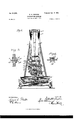
- Figure l is a side elevation of my machine inner end of the boom 11 is supported as folready for operation; Fig. 2, a rear elevation lows:
- the boom is provided with a horizontal of the same with the boiler, engine, dipper, transverse slot, as shown in Fig. 1, in which dipper-arm, and boom removed;
- Fig. 3 a side slot is a toothed rack 11*.
- Through this slot elevation of a bearing of a shaft of a friction passes shaft 18, journaled upon the frame of 3 3 wheel hereinafter referred to, showing'a dethe machine and having rigidly secured therevice for moving one end of a shaft laterally; to a pinion ll in engagement with the toothed and Fig.
- shaft 15 is loosely jouranism connected with the engine of the manaled in the frame to allow lateral play of the chine.
- the friction -wheel 15 is lar rack 3, upon which is a circular track 4;. driven by connections with the engine, the 5 is a stout platform or frame resting iipon wheel 15 being arranged to be thrown into and 50 grooved rollers or wheels 6, which rest and out of engagement withthe driving-wheel and travel upon the circular track 4.
- This lever may be held in any desired position by means of the pegs or stops 16.
- the dipper-arm 12 is swung on its pivot 12 by means of the rope or chain 17, secured to the outer extremity of the dipper-arm and passingoveraseries of pulleys, as shown, to drum 17.
- This drum is driven and controlled by the driving friction- ⁇ vheel15 through an intermediate friction-wheel 17 which is, as above described, thrown into and outof engagement with the driving anddriven wheels by means of lever 17.
- This lever may be secured in any desired position by means of stops or pegs 17.
- a drivingwheel 18 which may be driven either manually or by any suitable connection with an engine.
- the wheel 18 driven by a chain and sprocket 18 and lever 18 carrying a detent 18, arranged to be thrown into and out of gear with the driving sprocketwheel.
- the pinion on the shaft 18 is rotated, the boom 11 is projected and retracted, and thus when the dipper is in the position shown in Fig. 1 it may be driven bodily and power-- fully in a right line directly against the face of a bank. This is found to be a valuable feature in finishing excavations having vertical banks or faces.
- the pinion 7 on shaft 8 may be driven in either direction and the turn-table caused to swing as may be desired by means of a pair of cone frictionwhee1s 19, mounted and longitudinally movable upon shaft 19, suitably connected with the engine.
- the cones 19 are adapted to be thrown into or out of engagement with opposite sides of cone-wheel 20, fixed upon the shaft 8.
- the operation of my device is as follows: The machine being in position and the engine being in motion, the boom 11 is lowered to the desired point by paying out the rope or chain 14.
- the cutting portion of the dipper or shaft 13 may now be caused to describe the arc of a circle by winding up the rope or chain 17 upon its drum, thus swinging the dipperarm on its pivot.
- the dipper may be forced powerfully forward in a right line by means of the rack 11 and pinion on shaft 18.
- the boom may be lifted by means of the rope or chain 14.
- the dipper may be given, either simultaneously or separately, three different motions'viz., a curvilinear motion upon its pivot 12, a horizontal movement with the boom 11, and a vertical movement by means of the rope or chain 14.
- the dipper having been filled and being ready to dump, a lever or treadle (not shown) throws the friction-gear 19 20 into operation.
- the device is now swung upon its turn-table to the proper position, where the load is dumped in the usual manner. Now by a reversal of the above operation the dipper or shovel is returned to the proper place and the operation is repeated, and so on.
- a boom In an excavating-machine, a boom, a dipper-arm, a dipper or shovel secured to said dipper-arm, pivotal connections between the boom and the dipper-arm, means for longitudinally projecting and retracting the boom, means for swinging the dipper-arm upon its pivot, and means for raising and lowering the boom.
- An excavating-machine comprising a truck, a turn-table thereon, an engine and boiler mounted on the turn-table at one side,-
- a derrick on the turn-table at the opposite side, a boom, means for projecting and retracting the boom, means for raising and lowering the boom, a dipper-arm having a dipper or shovel secured thereto, pivotal connections between the end of the boom and the dipper-arm, and means for swinging said dipper-arm on said pivot.
Description
' Patented Apr. 9, 190i. D. H. SNYDER.
EXCAVATING MACHINE.
(Applicatioq filed May 7. 1900. (N 0 M 0 d e l 2 Sheets-Sheet I.
WITNESSES.
m: NORRIS PETERS co. wora'umo WASHINGTON, o, c
No. 67|,925. Patented Apr. 9, l90l.
D. H. SNYDER.
EXCAVATING MACHINE (Application filed May 7. 1900. (No Model.) 2 $heets-8heet 2.
UNITED STATEs PATENT OFFICE.
' DILLON H. SNYDER, OF TOLEDO, OHIO, ASSIGNOR OF ONE-HALF TO CHARLES M. HARRISON AND NATHAN BABCOOK, OF NAPOLEON, OHIO.
EXCAVATlNG-MACHINE.
SPECIFICATION forming part of Letters Patent No. 671,925, dated April 9, 1901.
Application filed May '7, 1900. Serial No. 15,698. (No model.)
T all wh WI i may 00711067711: having a vertical shaft 8, is suitably connect- Be it known that I, DILLON H. SNYDER, a ed with the engine of the machine, and by the citizen of the United States, residing at Torotation of this pinion in engagement with the ledo, in the county of Lucas and State of Ohio, circular rack 3 the frame or platform 5 and its 5 have invented certain new and useful Imsuperimposed load are caused to rotate horiprovements in Excavating-Machines; and I zontally, as a turn-table. The boiler 9 and do declare the following to be afull, clear, and the engine (not shown in the drawings) are exact description of theinvention, such aswill fixed upon a projecting portion of the floorenable others skilled in the art to which it apframe 5 at one side of the machine, the weight IO pertains to make and use the same, reference of the derrick, dipper, dipper-arm, and boom beinghad to the accompanying drawings, and being disposed at the opposite side of the to the figures of reference marked thereon, floor-platform, so that the two weights balwhich form a part of this specification. 'ance each other. From the side of the floor- My invention relates to small portable exframe opposite the boiler spring two upright 15 cavating-machines especially well adapted for pieces 10, suitably braced, as shown, and
operating in pits and trenches; and one object forming a derrick. is to provide a construction whereby the dig- 11 is a boom projecting between the mem ging operation may be carried on in any dibers of the derrick l0 and having pivot-ally serection without moving the base of the macured to its outer extremity, as at 12*, the dip- 2o chine. per-arm 12, carrying a dipper or shovel 13 of The further object of myinventionis to prothe usual form or of any other preferred convide a novel and convenient mechanism for struction. The boom 11 is supported at its powerfullyactuating and for guiding and con- 'outer end by means of rope or chain 14, which trolling the scoop or shovel hereinafter reat one end is secured to the boom, as at 1 1*, 25 ferred to. I passing thence over pulley 14 thence over a I attain these objects by means of the mechpulley 14 on the boom, thence over a roller anism and arrangement of parts hereinafter 1 st at the top of the boom, and thence to a described, and shown and illustrated in the drum 14$, journaledin a stout upright frame accompanying drawings, in whichin the rear of the machine. The opposite or 30 Figure l is a side elevation of my machine inner end of the boom 11 is supported as folready for operation; Fig. 2, a rear elevation lows: The boom is provided with a horizontal of the same with the boiler, engine, dipper, transverse slot, as shown in Fig. 1, in which dipper-arm, and boom removed; Fig. 3, a side slot is a toothed rack 11*. Through this slot elevation of a bearing of a shaft of a friction passes shaft 18, journaled upon the frame of 3 3 wheel hereinafter referred to, showing'a dethe machine and having rigidly secured therevice for moving one end of a shaft laterally; to a pinion ll in engagement with the toothed and Fig. 4: is an enlarged transverse sectional rack 11*. It will be seen that the shaft 18 elevation of the boom, hereinafter referred to, while permitting the longitudinal movement together with the shaft, pinion, and rack proof the boom forms a support for the boom. 0 o vided to actuate said boom longitudinally. The druml isdriven and controlledby means Like numerals of reference indicate like of a friction-wheel 15 and an intermediate parts throughout the drawings. friction-wheel 15*, mounted fixedly on shaft In the drawings, 1 is a stout frame mounted 15 journaled at one end in box 15 which on a low truck, the wheels of which, 2, may slides in housing 15, as illustrated in Fig. 3. 5 45 be actuated manually orby any suitable mech- The opposite end of shaft 15 is loosely jouranism connected with the engine of the manaled in the frame to allow lateral play of the chine. Upon the frame 1 is secured a circusliding box 15". The friction -wheel 15 is lar rack 3, upon which is a circular track 4;. driven by connections with the engine, the 5 is a stout platform or frame resting iipon wheel 15 being arranged to be thrown into and 50 grooved rollers or wheels 6, which rest and out of engagement withthe driving-wheel and travel upon the circular track 4. A pinion 7, the driven wheel by means of lever 16, which is connected with sliding box 15 by means of connecting-rod 16 (See Fig. This lever may be held in any desired position by means of the pegs or stops 16. The dipper-arm 12 is swung on its pivot 12 by means of the rope or chain 17, secured to the outer extremity of the dipper-arm and passingoveraseries of pulleys, as shown, to drum 17. This drum is driven and controlled by the driving friction-\vheel15 through an intermediate friction-wheel 17 which is, as above described, thrown into and outof engagement with the driving anddriven wheels by means of lever 17. This lever may be secured in any desired position by means of stops or pegs 17.
Upon the boom 11, at its end opposite the pivot 12, is a rack engaged by a pinion upon the shaft 18. Upon this shaft is a drivingwheel 18, which may be driven either manually or by any suitable connection with an engine. In this example I have shown by way of illustration the wheel 18 driven by a chain and sprocket 18 and lever 18 carrying a detent 18, arranged to be thrown into and out of gear with the driving sprocketwheel. hen the pinion on the shaft 18 is rotated, the boom 11 is projected and retracted, and thus when the dipper is in the position shown in Fig. 1 it may be driven bodily and power-- fully in a right line directly against the face of a bank. This is found to be a valuable feature in finishing excavations having vertical banks or faces.-
The pinion 7 on shaft 8 may be driven in either direction and the turn-table caused to swing as may be desired by means of a pair of cone frictionwhee1s 19, mounted and longitudinally movable upon shaft 19, suitably connected with the engine. The cones 19 are adapted to be thrown into or out of engagement with opposite sides of cone-wheel 20, fixed upon the shaft 8.
The operation of my device is as follows: The machine being in position and the engine being in motion, the boom 11 is lowered to the desired point by paying out the rope or chain 14. The cutting portion of the dipper or shaft 13 may now be caused to describe the arc of a circle by winding up the rope or chain 17 upon its drum, thus swinging the dipperarm on its pivot. If desired, the dipper may be forced powerfully forward in a right line by means of the rack 11 and pinion on shaft 18. At the same time, if desired, the boom may be lifted by means of the rope or chain 14. Thus it will be seen that the dipper may be given, either simultaneously or separately, three different motions'viz., a curvilinear motion upon its pivot 12, a horizontal movement with the boom 11, and a vertical movement by means of the rope or chain 14. The dipper having been filled and being ready to dump, a lever or treadle (not shown) throws the friction-gear 19 20 into operation. The device is now swung upon its turn-table to the proper position, where the load is dumped in the usual manner. Now by a reversal of the above operation the dipper or shovel is returned to the proper place and the operation is repeated, and so on.
Having described my invention, what I claim, and desire to secure by Letters Patent, 1S.
1. In an excavating-machine, a boom, a dipper-arm, a dipper or shovel secured to said dipper-arm, pivotal connections between the boom and the dipper-arm, means for longitudinally projecting and retracting the boom, means for swinging the dipper-arm upon its pivot, and means for raising and lowering the boom.
2. An excavating-machine, comprising a truck, a turn-table thereon, an engine and boiler mounted on the turn-table at one side,-
a derrick on the turn-table at the opposite side, a boom, means for projecting and retracting the boom, means for raising and lowering the boom, a dipper-arm having a dipper or shovel secured thereto, pivotal connections between the end of the boom and the dipper-arm, and means for swinging said dipper-arm on said pivot.
In testimony whereof I affix my signature in presence of two witnesses.
DILLON H. SNYDER. WVitnesses:
WILBER A. OWEN, L. E. BROWN.
Priority Applications (1)
| Application Number | Priority Date | Filing Date | Title |
|---|---|---|---|
| US1569800A US671925A (en) | 1900-05-07 | 1900-05-07 | Excavating-machine. |
Applications Claiming Priority (1)
| Application Number | Priority Date | Filing Date | Title |
|---|---|---|---|
| US1569800A US671925A (en) | 1900-05-07 | 1900-05-07 | Excavating-machine. |
Publications (1)
| Publication Number | Publication Date |
|---|---|
| US671925A true US671925A (en) | 1901-04-09 |
Family
ID=2740478
Family Applications (1)
| Application Number | Title | Priority Date | Filing Date |
|---|---|---|---|
| US1569800A Expired - Lifetime US671925A (en) | 1900-05-07 | 1900-05-07 | Excavating-machine. |
Country Status (1)
| Country | Link |
|---|---|
| US (1) | US671925A (en) |
Cited By (1)
| Publication number | Priority date | Publication date | Assignee | Title |
|---|---|---|---|---|
| US2418299A (en) * | 1944-11-18 | 1947-04-01 | Howard F Gorsuch | Power shovel |
-
1900
- 1900-05-07 US US1569800A patent/US671925A/en not_active Expired - Lifetime
Cited By (1)
| Publication number | Priority date | Publication date | Assignee | Title |
|---|---|---|---|---|
| US2418299A (en) * | 1944-11-18 | 1947-04-01 | Howard F Gorsuch | Power shovel |
Similar Documents
| Publication | Publication Date | Title |
|---|---|---|
| US671925A (en) | Excavating-machine. | |
| US1008338A (en) | Tractor-hoist and tractor-excavator. | |
| US1185427A (en) | Power-shovel. | |
| US939227A (en) | Dredge. | |
| US501242A (en) | Straw-stacker | |
| US419401A (en) | bald by | |
| US601106A (en) | The nor | |
| US412303A (en) | Straw-stacker | |
| US769923A (en) | Car-unloading device. | |
| US750005A (en) | quertier | |
| US941571A (en) | Loading and unloading device. | |
| US388910A (en) | Excavator | |
| US768362A (en) | Excavating-machine. | |
| US645175A (en) | Excavating-machine. | |
| US225001A (en) | Excavating-machine | |
| US809689A (en) | Excavating-machine. | |
| US853804A (en) | Ditching-machine. | |
| US956507A (en) | Wagon jack or elevator. | |
| US514829A (en) | Dredger | |
| US633850A (en) | Steam shovel or excavator. | |
| US880937A (en) | Ditching-machine. | |
| US1317696A (en) | Machine eor handling materials | |
| US868267A (en) | Excavator. | |
| US1078842A (en) | Excavator. | |
| US759764A (en) | Excavating-machine. |