US7721640B2 - Cable operated gas cylinder - Google Patents
Cable operated gas cylinder Download PDFInfo
- Publication number
- US7721640B2 US7721640B2 US11/766,676 US76667607A US7721640B2 US 7721640 B2 US7721640 B2 US 7721640B2 US 76667607 A US76667607 A US 76667607A US 7721640 B2 US7721640 B2 US 7721640B2
- Authority
- US
- United States
- Prior art keywords
- taper holder
- release arm
- holder
- taper
- cable
- Prior art date
- Legal status (The legal status is an assumption and is not a legal conclusion. Google has not performed a legal analysis and makes no representation as to the accuracy of the status listed.)
- Active, expires
Links
Images


Classifications
-
- A—HUMAN NECESSITIES
- A47—FURNITURE; DOMESTIC ARTICLES OR APPLIANCES; COFFEE MILLS; SPICE MILLS; SUCTION CLEANERS IN GENERAL
- A47C—CHAIRS; SOFAS; BEDS
- A47C3/00—Chairs characterised by structural features; Chairs or stools with rotatable or vertically-adjustable seats
- A47C3/20—Chairs or stools with vertically-adjustable seats
- A47C3/30—Chairs or stools with vertically-adjustable seats with vertically-acting fluid cylinder
-
- A—HUMAN NECESSITIES
- A47—FURNITURE; DOMESTIC ARTICLES OR APPLIANCES; COFFEE MILLS; SPICE MILLS; SUCTION CLEANERS IN GENERAL
- A47C—CHAIRS; SOFAS; BEDS
- A47C3/00—Chairs characterised by structural features; Chairs or stools with rotatable or vertically-adjustable seats
- A47C3/20—Chairs or stools with vertically-adjustable seats
-
- F—MECHANICAL ENGINEERING; LIGHTING; HEATING; WEAPONS; BLASTING
- F16—ENGINEERING ELEMENTS AND UNITS; GENERAL MEASURES FOR PRODUCING AND MAINTAINING EFFECTIVE FUNCTIONING OF MACHINES OR INSTALLATIONS; THERMAL INSULATION IN GENERAL
- F16K—VALVES; TAPS; COCKS; ACTUATING-FLOATS; DEVICES FOR VENTING OR AERATING
- F16K31/00—Actuating devices; Operating means; Releasing devices
- F16K31/44—Mechanical actuating means
- F16K31/46—Mechanical actuating means for remote operation
- F16K31/465—Mechanical actuating means for remote operation by flexible transmission means, e.g. cable, chain, bowden wire
Definitions
- the present invention relates generally to a cable operated gas cylinder and more particularly to a cable operated gas cylinder, gotten rid of the phenomenon of kinking or twisting of the cable upon rotation of the chair, thereby operable with enhanced operation reliability and product durability.
- a gas cylinder is an apparatus formed between a seat of a chair and a chair base for being used in adjusting height of the seat. Also, the gas cylinder may be applied to a variety of apparatus such as an impulse buffering apparatus for a vehicle as well as an apparatus for adjusting height of a seat of a chair.
- a gas opening/closing pin should operate up and down directions with use of a separate knob formed on the lower side of a seat of a chair. Therefore, there exists a problem that a user should bend his/her body in order to operate the knob.
- the registered patent “Adjusting Member for Height of Chair” discloses a gas cylinder operating with use of a cable, and additionally having: a separate button additionally installed on a predetermined structure exemplified as an arm rest of a chair; and a cable operated by the button, and the gas cylinder is characterized in that its up and down movements are performed by button pressing.
- the apparatus On the first place, the apparatus is so complicated that a plurality of various parts is used, and assembling process of the parts is difficult. Also, as a plurality of parts is used, manufacturing costs are increased.
- the cable will twist and kink so that operation reliability of the product becomes lower and even further the product itself gets disordered.
- An object of the present invention is therefore to provide a cable operated gas cylinder, gotten rid of the phenomenon of kinking or twisting of the cable upon rotation of the chair, thereby operable with enhanced operation reliability and product durability.
- Another object of the present invention is to provide a cable operated gas cylinder which can be more conveniently operated by a user and more simply assembled at the production spot.
- Still another object of the present invention is to provide an operating apparatus of gas cylinder operable with even more increased operational reliability and stability.
- Still another object of the present invention is to provide an operating apparatus of gas cylinder with which can be produced at still further lowered production cost of the gas cylinder.
- a cable operated gas cylinder comprises: a base tube of hollow tube shape; a spindle which is inserted at hollow part in said base tube and capable of moving up and down according to height adjusting; a cylinder which is, being filled with a gas, mounted within said spindle; a piston which is in contact with inner peripheral plane of said cylinder so as to divide the gas-filled space within said cylinder into upper part and lower part; a pipe holder which is installed at upper part of said cylinder and seals airtight the upper part of said cylinder; a gas opening/closing pin which is mounted penetratingly through central part of said pipe holder and for controlling getting in and out of the gas filled within said cylinder; a release arm which is installed at upper side of said gas opening/closing pin and for controlling the opening/closing of said gas opening/closing pin; a cable, whose one end is fixed at said release arm, for controlling turning of said release arm when being pulled by external force;
- a chair adopting aforementioned configuration has an advantageous effect that its motion reliability and product durability are enhanced because the cable does not twist or kink even when the chair rotates.
- manufacturing process at work site can be more simplified as well as convenience in use can be achieved. Due to its simplified configuration, operation stability and reliability of the gas cylinder can be increased, but production cost thereof can be far much lowered.
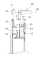
- FIG. 1 is a cross-sectional view of a gas cylinder according to the present invention
- FIG. 2 is a cross-sectional view of a release arm in a gas cylinder according to the present invention
- FIG. 3 is a top plan view of a taper holder in a gas cylinder according to the present invention.
- FIG. 4 is a cross-sectional view taken along line 4 - 4 in FIG. 3 ;
- FIG. 5 is a front view of a taper holder in a gas cylinder according to the present invention.
- FIG. 6 is an external perspective view of a taper holder in a gas cylinder according to the present invention.
- FIG. 7 is a cross-sectional view of a taper holder supporter in a gas cylinder according to the present invention.
- FIG. 8 is a cross-sectional view in combination of a taper holder and a taper holder supporter in a gas cylinder according to the present invention.
- FIG. 9 is a drawing to explain the motion of the present invention, describing a state when external force is not applied at the gas opening/closing pin.
- FIG. 10 is a drawing to explain the motion of the present invention, describing a state when external force is applied at the gas opening/closing pin.
- FIG. 1 is a cross-sectional view of a gas cylinder according to the present invention.
- a gas cylinder according to the present invention comprises: a base tube 110 of a hollow tube shape; a spindle 120 of a hollow tube shape inserted at the hollow part of said base tube 110 ; a tube guide 115 and bushing 117 further inserted at contact plane between said base tube 110 and said spindle 120 in order that up and down movement of said spindle can be done smoothly; and a cylinder 140 of a hollow tube shape further formed at inner peripheral plane of said spindle 120 .
- Said gas cylinder further comprises: a piston 130 which is in contact with the inner peripheral plane of said cylinder 140 for dividing the gas-filled space in the cylinder 140 into upper chamber 161 and lower chamber 162 ; a piston rod 135 prolonged downwards whose one end is fixed at said piston 130 and the other end is fixed at lower end of said base tube 110 ; and a fixing clip 137 for fixing the other end of said piston rod 135 at said base tube 110 .
- Said gas cylinder further comprises: a pipe holder 152 for sealing airtight the upper part of said cylinder 140 ; a gas opening/closing pin 151 mounted penetratingly through central part of said pipe holder 152 for enabling the gas within said cylinder 140 to move; an orifice 153 formed within said pipe holder 152 for enabling the gas filled within said pipe holder 152 to move in and out when said opening/closing pin 151 is down; and at least one inner seal 154 inter-positioning at contact plane for airtight sealing between outer peripheral plane of said pipe holder 152 and inner peripheral plane of said spindle 120 and/or cylinder 140 .
- said cylinder is formed with a gas chamber 160 of predetermined length and nitrogen gas is filled in said gas chamber 160 .
- Said gas chamber 160 is divided by said piston 130 into two parts, i.e., upper chamber 161 and lower chamber 162 . Up and down movement of said spindle 120 makes change in the volumes between upper chamber 161 and lower chamber 162 .
- the pressure in said upper chamber 161 and lower chamber 162 maintains a pressure (P 2 ) which is higher than atmosphere (P 1 ).
- a gas flow path 163 is formed between said cylinder 140 and said spindle 120 for providing a path for gas to move between said upper chamber 161 and lower chamber 162 .
- a taper holder 180 formed further at upper side of said pipe holder 152 , a taper holder supporter 190 in order for said taper holder 180 to be put over rotationally, a release arm 170 by which a motion of pressing upper end of said gas opening/closing pin 151 can be done, and whose stop position and motion is guided by said tape holder 180 , and a cable 165 for enabling said release arm 170 to operate.
- Said base tube 110 , spindle 120 , cylinder 140 , release arm 170 , taper holder 180 , taper holder supporter 190 , or the like can preferably be made of metallic materials in order that these parts might be able to sustain against high pressure gas filled within the cylinder 140 and not be broken by stress applied from user's weight.
- material of said pipe holder 152 is metal. But the material thereof is not limited as within metal. Even plastic material might be used also with no limitation as long as it can furnish sufficient strength.
- One end of said cable 165 is connected with said release arm 170 , and the other end with predetermined button.
- a traditional button structure can be used as it is installed at armrest of a chair.
- one end of said cable 165 can be connected with said release arm 170 , and the other end with a predetermined lever.
- the button structure or lever structure formed at the other end of said cable 165 in description as above is only for explanatory example. Any structure capable of pulling the cable 165 can be used only if such structure is able to pull the cable 165 within a range of certain length. It does not matter if any other cable-pulling structure already known in any industrial field other than the field related with a gas cylinder is used.
- a cable holder 166 is further formed fixed at upper end of said taper holder 180 in order that position of said cable 165 is guided.
- Said release arm 170 rotates around a predetermined rotational center shaft for operating of said gas opening/closing pin 151 .
- its position is not fixed, or fixed shaft structure is not adopted as a predetermined center shaft for said rotational center shaft. But by insertion into a predetermined space formed within said taper holder 180 , its position can be appointed. Lower side of said release arm 170 is supported by said gas opening/closing pin 151 .
- said taper holder 180 includes, in its inner space, said release arm 170 and is inserted at upper end of said spindle 120 . Particularly, by insertion of said release arm 170 within said taper holder 180 for settling its position, the installation process for release arm 170 is finished. Therefore, in this way there is no limitation for said release arm 170 to be operated.
- said taper holder supporter 190 is formed as a hollow cylindrical shape. At inner space of taper holder supporter 190 , the taper holder 180 is combined. In other words, said taper holder supporter 190 is combined with upper end part of inner peripheral plane of said spindle 120 , and said taper holder 180 is inserted at inner peripheral plane of taper holder supporter 190 .
- outer diameter of said taper holder 180 can be formed smaller to some extent than inner diameter of said taper holder supporter 190 . Therefore, in case said cable 165 changes its direction following rotation of chair, said taper holder 180 can rotate by guiding of taper holder supporter 190 .
- the cable 165 whose position is fixed by insertion at said release arm 170 , after its penetration through release arm 170 , can be fixed incorporated at end thereof or placed on release arm 170 thanks to a hanger 167 having an additional commodity fixed thereto.
- Unexplained numeral 155 is a washer.
- said taper holder 180 can rotate together with rotation of cable 165 connected to taper holder 180 . Hence, kinking or twisting of said cable 165 can be advantageously prevented.
- this gas flow moves to said dented part, and further moves through said orifice 153 to a gas flow path 163 formed between spindle 120 and cylinder 140 . Also, this gas flow downward along said gas flow path 163 moves further to said lower chamber 162 . Accordingly, volume of said lower chamber 162 becomes larger than that of said upper chamber 161 , and spindle 120 goes down. Together with these operations, total length of gas cylinder becomes smaller, so seat of the chair moves down.
- the external force pulling the cable 165 is removed. If said external force is removed, said gas opening/closing pin 151 moves its position upwards due to the pressure applied from a high pressure gas within upper chamber 161 ; said release arm 170 and cable 165 can recover to their original positions. Because said gas opening/closing pin 151 has moved upward, gas transfer stops between said gas chambers 161 & 162 , and accordingly the position of chair seat gets fixed.
- one end of said cable 165 is connected with said release arm 170 , and the other end with a predetermined button or lever.
- said button can be installed at armrest part of a chair, and the lever at a tilt mechanism of chair seat.
- the button installed at armrest of chair and the cable 165 connected with said button also rotate together.
- the taper holder 180 connected with said cable 165 and release arm 170 can also rotate in accordance with guiding by said taper holder supporter 190 .
- the phenomenon of kinking or twisting of said cable 165 can be prevented.
- release arm 170 and taper holder 180 will be described in detail for their configuration.
- FIG. 2 is a cross-sectional view of a release arm according to the present invention.
- Said release arm can be formed by same thickness for its overall aspect, so it will be described based only on the cross-sectional view thereof.
- Said release arm 170 comprises: a hooking prominence 171 which functions as a rotational center by protruding in a shape of a peak formed at one side of lower end part of said release arm; a pin pressing part 172 of slowly curved shape formed at approximately opposite side to said hooking prominence 171 ; a vertical interval retaining part 173 which is formed extendedly upward from said pin pressing part 172 ; a horizontal interval retaining part 174 which is formed bent to approximately horizontal direction from said vertical interval retaining part 173 ; and a cable hooking part 175 which is formed extendedly further upward from said horizontal interval retaining part 174 .
- said cable hooking part 175 comprises: a cable hooking end 176 formed dented at one side of the cable hooking part 175 in order for end of cable to be fixed, and a cable insertion hole 177 formed penetratingly through cable hooking part 175 at the dented position of said cable hooking end 176 .
- a predetermined hanger (referring to 167 of FIG. 1 ) can be placed at said cable hooking part 175 in order for the cable not to slip out (referring to 165 of FIG. 1 ), but it is not compulsory.
- FIG. 3 is a top plan view of a taper holder in a gas cylinder according to the present invention
- FIG. 4 is a cross-sectional view taken along line 4 - 4 in FIG. 3
- FIG. 5 is a front view of a taper holder in a gas cylinder according to the present invention
- FIG. 6 is an external perspective view of a taper holder in a gas cylinder according to the present invention.
- a taper holder 180 of a predetermined shape further comprised of an arm insertion hole 181 which is formed larger to some extent than the thickness of said release arm 170 so that the release arm 170 can be inserted therein; an arm guide part 182 which forms both side walls of said arm insertion hole 181 ; a guide plane 186 of a shape slowly curved in a particular form similar to shift position of the pin pressing part 172 in order that rotation of said release arm 170 can be smoothly guided by contact plane to plane with said pin pressing part (referring to 172 of FIG. 2 ); and a cable insertion groove 185 which is formed dented at upper end part of said arm guide part 182 .
- a cable holder 166 having a predetermined hole formed therein is fixed at said cable insertion groove 185 in order that cable position can be guided.
- said arm guide part 182 is formed with a lower arm guide part 183 wherein at least one part of hooking prominence 171 of said release arm 170 , pin pressing part 172 , and vertical interval retaining part 173 is inserted. And there are further formed with an upper arm guide part 184 wherein at least one part of said cable hooking part 175 , horizontal interval retaining part 174 , and said vertical interval retaining part 173 gets inserted.
- an opening can be formed at one side of said taper holder, that is, at entrance of arm insertion hole 181 .
- a part of side of said cylinder-shaped taper holder 180 may be cut out. In this way, production cost can be reduced as much as this cut-out portion.
- Said vertical interval retaining part 173 being a part of said release arm 170 , enables said release arm 170 to be relieved over from the range formed by a lower arm guide part 182 and move back and forth. Especially, said vertical interval retaining part 173 can be shaken back and forth within the range of width of said arm insertion hole 181 (referring to interval C of FIG. 4 ).
- said vertical interval retaining part 173 can, due to enlarged momentum by enlargement of distance between said cable hooking part 175 and said pin pressing part 172 , enable an external force applied to cable hooking part 175 to be even larger at said pin pressing part 172 . In this way, though in case when the pulling force for cable hooking part 175 is small, the force applied to pin pressing part 172 gets larger in some extent, so the reliability in operation of the gas cylinder can be enhanced.
- said horizontal interval retaining part 174 is formed bent for a predetermined length from said vertical interval retaining part 173 to approximately horizontal direction and more particularly to left-upper side direction, so that operational width of release arm 170 can be smoothly secured when cable 165 is pulled.
- said horizontal interval retaining part 174 were not formed as described above, the upper end part of release arm 170 would interfere with said upper arm guide part 184 on maximum pulling of said release arm 170 . That is why said horizontal interval retaining part 174 should be formed for preventing such interference.
- Said release arm 170 gets inserted at lower side of said taper holder 180 and positioned at said arm insertion hole 181 .
- opened part at lower side of said arm insertion hole 181 is formed larger than said release arm 170 , so said release arm 170 can be inserted without any obstruction.
- release arm 170 gets received within said arm insertion hole 181 , said pin pressing part 172 contacts plane to plane with said guide plane 186 , so release arm 170 is stably supported at its one side. And said hooking prominence 171 gets contacted with and caught at arm hooking part 192 of taper holder supporter 190 (which will be described later), so the release arm 170 is stably supported at its other side. Moreover, a gas opening/closing pin 151 placed at lower side of said release arm 170 can sustain weight of release arm 170 , and thus overall position of said release arm 170 can be stably maintained.
- release arm 170 when said release arm 170 changes its position, release arm 170 is guided for its position change according to contacting state between pin pressing part 172 and guide plane 186 and contacting state between hooking prominence 171 and arm hooking part 192 , and therefore said release arm 170 can operate stably.
- said hooking prominence 171 can function in operation as an overall central point for rotation of release arm 170 .
- FIG. 7 is a cross-sectional view of a taper holder supporter in a gas cylinder according to the present invention
- FIG. 8 is a cross-sectional view in combination of a taper holder and a taper holder supporter in a gas cylinder according to the present invention.
- said taper holder supporter 190 is formed in a hollow cylindrical shape. Said taper holder supporter 190 is formed at hollow part thereof with a combination hole 191 whereto said taper holder 180 can be inserted.
- said combination hole 191 of taper holder supporter 190 is formed to have a stepped portion in such a manner that diameter of lower part is larger than that of upper part.
- an arm hooking part 192 is formed at this stepped portion in order for taper holder 180 not to slip out from taper holder supporter 190 .
- said taper holder 180 is combined with the combination hole 191 according to a way of insertion from bottom upward.
- the outer diameter of lower end of said taper holder 180 is formed a bit larger than diameter of arm hooking part 192 of said taper holder supporter 190 , so that said taper holder 180 can not escape upward out of taper holder supporter 190 .
- the outer diameter of upper end of said taper holder 180 is preferably formed smaller in some extent than diameter of said taper holder supporter 190 . This is so in order that taper holder 180 connected to said cable 165 can rotate smoothly when said cable 165 rotates. By such configurations, said taper holder 180 can rotate along the inner peripheral plane of said taper holder supporter 190 . Therefore, even though a chair mounted by a gas cylinder is rotated by a user, said cable 165 can be prevented from kinking or twisting.
- a lubricant can be applied at the contact plane between outer peripheral plane of said taper holder 180 and inner peripheral plane of said taper holder supporter 190 , so that said taper holder 180 can smoothly rotate.
- FIG. 9 is a drawing to explain the motion of the present invention, describing a state when external force is not applied at the gas opening/closing pin.
- FIG. 10 is a drawing to explain the motion of the present invention, describing a state when external force is applied at the gas opening/closing pin.
- said pin pressing part 172 is pressing gas opening/closing pin 151 , and it is possible for the gas to flow and move between said chambers 161 and 162 . Accordingly, said gas cylinder can move up and down. That is, in case a user is seated on the seat of chair, the spindle moves downwards so as to make gas cylinder shrink; and in case a user is not seated on the seat of chair, the spindle moves upwards so as to make gas cylinder expand.
- the release arm 170 upon operation of said release arm 170 , the release arm 170 is capable of stably operating because lower plane at slowly curved part of said pin pressing part 172 presses said gas opening/closing pin 151 while side plane at slowly curved part of said pin pressing part 172 contacts plane to plane with said guide plane 186 . Moreover, thanks to said hooking prominence 171 being caught at said arm hooking part 192 , said release arm 170 does not change its position by parallel movement, but does rotational movement around a rotational center as the peak of end of hooking prominence 171 .
- release arm 170 can be supported for its movement by taper holder 180 without any additional configurations.
- the weight of release arm 170 can be supported by gas opening/closing pin 151 , so release arm 170 can be stably positioned.
- the cable does not kink or twist due to the taper holder formed rotational, and accordingly operation reliability and product durability are enhanced.
- the cable operated gas cylinder according to present invention can be operated more conveniently by a user and assembled more simply at production spot.
- the cable operated gas cylinder according to present invention has advantageous effects of further more increased reliability and stability in operation and still further lowered production cost.
Abstract
Description
Claims (10)
Applications Claiming Priority (2)
| Application Number | Priority Date | Filing Date | Title |
|---|---|---|---|
| KR1020060058349A KR100830598B1 (en) | 2006-06-27 | 2006-06-27 | Operating apparatus of gas cylinder with cable |
| KR10-2006-0058349 | 2006-06-27 |
Publications (2)
| Publication Number | Publication Date |
|---|---|
| US20080041224A1 US20080041224A1 (en) | 2008-02-21 |
| US7721640B2 true US7721640B2 (en) | 2010-05-25 |
Family
ID=39100116
Family Applications (1)
| Application Number | Title | Priority Date | Filing Date |
|---|---|---|---|
| US11/766,676 Active 2028-04-19 US7721640B2 (en) | 2006-06-27 | 2007-06-21 | Cable operated gas cylinder |
Country Status (2)
| Country | Link |
|---|---|
| US (1) | US7721640B2 (en) |
| KR (1) | KR100830598B1 (en) |
Cited By (7)
| Publication number | Priority date | Publication date | Assignee | Title |
|---|---|---|---|---|
| US20120104809A1 (en) * | 2010-10-28 | 2012-05-03 | Jung Yu Hsu | Control device for adjustable bicycle seat |
| US20170096186A1 (en) * | 2015-10-04 | 2017-04-06 | Shang-Hua Lai | Height adjustment device for bicycle saddle |
| US10034538B1 (en) | 2017-05-05 | 2018-07-31 | Sauder Woodworking Co. | Height-adjustable work surface assembly |
| US11104395B2 (en) * | 2019-04-06 | 2021-08-31 | D3 Innovation Inc. | Dropper post assembly for a bicycle |
| US11767073B2 (en) | 2020-10-09 | 2023-09-26 | D3 Innovation Inc. | Bicycle dropper seat post assembly with a locking spring cartridge |
| US11780520B1 (en) | 2022-04-10 | 2023-10-10 | D3 Innovation Inc. | Bicycle dropper seat post assembly with a narrow gas spring cartridge |
| US11834121B2 (en) | 2022-04-10 | 2023-12-05 | D3 Innovation Inc. | Bicycle dropper seat post assembly with a bottom mounted gas spring cartridge |
Families Citing this family (4)
| Publication number | Priority date | Publication date | Assignee | Title |
|---|---|---|---|---|
| KR101658188B1 (en) * | 2010-01-14 | 2016-09-22 | 주식회사 삼홍사 | Gas cylinder with cable |
| KR101909769B1 (en) * | 2014-09-01 | 2018-10-18 | 엘에스엠트론 주식회사 | Adjusting Height Assembly for Control Box |
| CN106068040B (en) * | 2016-07-22 | 2023-03-31 | 圣拓热控科技江苏有限公司 | Explosion-proof tail terminal box |
| KR102473449B1 (en) | 2021-03-24 | 2022-12-01 | 유한회사 애니체 | Height adjusting device for chair |
Citations (5)
| Publication number | Priority date | Publication date | Assignee | Title |
|---|---|---|---|---|
| KR20000007287A (en) | 1998-07-02 | 2000-02-07 | 이세용 | Adjusting member for height of chair |
| KR20000008481A (en) | 1998-07-14 | 2000-02-07 | 이세용 | Gas cylinder type of height adjuster for chair |
| US20040124570A1 (en) * | 2002-12-31 | 2004-07-01 | Song Huh | Gas cylinder |
| KR20040092715A (en) | 2003-04-25 | 2004-11-04 | 주식회사 삼홍사 | Operating apparatus of gas cylinder with cable |
| US20050022661A1 (en) * | 2003-07-23 | 2005-02-03 | Zanden James Vander | Snap-in rotatable cylinder control |
Family Cites Families (2)
| Publication number | Priority date | Publication date | Assignee | Title |
|---|---|---|---|---|
| JPH05245014A (en) * | 1992-03-05 | 1993-09-24 | Tokico Ltd | Bearing device |
| KR200355151Y1 (en) | 2004-04-13 | 2004-07-02 | 주식회사 한국가스스프링 | A opening and closing switch structure for valve-pin control of gas cylinder |
-
2006
- 2006-06-27 KR KR1020060058349A patent/KR100830598B1/en active IP Right Grant
-
2007
- 2007-06-21 US US11/766,676 patent/US7721640B2/en active Active
Patent Citations (5)
| Publication number | Priority date | Publication date | Assignee | Title |
|---|---|---|---|---|
| KR20000007287A (en) | 1998-07-02 | 2000-02-07 | 이세용 | Adjusting member for height of chair |
| KR20000008481A (en) | 1998-07-14 | 2000-02-07 | 이세용 | Gas cylinder type of height adjuster for chair |
| US20040124570A1 (en) * | 2002-12-31 | 2004-07-01 | Song Huh | Gas cylinder |
| KR20040092715A (en) | 2003-04-25 | 2004-11-04 | 주식회사 삼홍사 | Operating apparatus of gas cylinder with cable |
| US20050022661A1 (en) * | 2003-07-23 | 2005-02-03 | Zanden James Vander | Snap-in rotatable cylinder control |
Cited By (9)
| Publication number | Priority date | Publication date | Assignee | Title |
|---|---|---|---|---|
| US20120104809A1 (en) * | 2010-10-28 | 2012-05-03 | Jung Yu Hsu | Control device for adjustable bicycle seat |
| US8308124B2 (en) * | 2010-10-28 | 2012-11-13 | Jung Yu Hsu | Control device for adjustable bicycle seat |
| US20170096186A1 (en) * | 2015-10-04 | 2017-04-06 | Shang-Hua Lai | Height adjustment device for bicycle saddle |
| US9637192B2 (en) * | 2015-10-04 | 2017-05-02 | Shang-Hua Lai | Height adjustment device for bicycle saddle |
| US10034538B1 (en) | 2017-05-05 | 2018-07-31 | Sauder Woodworking Co. | Height-adjustable work surface assembly |
| US11104395B2 (en) * | 2019-04-06 | 2021-08-31 | D3 Innovation Inc. | Dropper post assembly for a bicycle |
| US11767073B2 (en) | 2020-10-09 | 2023-09-26 | D3 Innovation Inc. | Bicycle dropper seat post assembly with a locking spring cartridge |
| US11780520B1 (en) | 2022-04-10 | 2023-10-10 | D3 Innovation Inc. | Bicycle dropper seat post assembly with a narrow gas spring cartridge |
| US11834121B2 (en) | 2022-04-10 | 2023-12-05 | D3 Innovation Inc. | Bicycle dropper seat post assembly with a bottom mounted gas spring cartridge |
Also Published As
| Publication number | Publication date |
|---|---|
| US20080041224A1 (en) | 2008-02-21 |
| KR20080000485A (en) | 2008-01-02 |
| KR100830598B1 (en) | 2008-05-21 |
Similar Documents
| Publication | Publication Date | Title |
|---|---|---|
| US7721640B2 (en) | Cable operated gas cylinder | |
| EP1527714B1 (en) | Chair | |
| US7231866B2 (en) | Opening and closing switch structure for valve pin control of gas cylinder | |
| US7059592B2 (en) | Gas cylinder | |
| JP6009891B2 (en) | Chair | |
| JP2019529753A (en) | Actuator for lifting system and lifting system for furniture door | |
| JP5089208B2 (en) | Door moving device | |
| US5342018A (en) | Single-handle faucet | |
| WO2004023937A1 (en) | Height-adjusters for saddles of bicycles | |
| JP2008531870A (en) | Door lock mechanism | |
| JP4848306B2 (en) | Opening restriction stopper device in casement window | |
| US5941620A (en) | Corner furnishing unit | |
| JP4714729B2 (en) | Locking structure of fuel lid | |
| JP2013536338A (en) | Foot door opener | |
| JP5784338B2 (en) | Hinge with closing mechanism | |
| KR101723604B1 (en) | Apparatus for adjusting height of chair | |
| JPH0581784B2 (en) | ||
| KR100576756B1 (en) | Operating apparatus of gas cylinder with cable | |
| KR101658188B1 (en) | Gas cylinder with cable | |
| JP2660439B2 (en) | Door check mechanism in vehicle door opening and closing device and door check operation mechanism using the same | |
| JP4456969B2 (en) | Curtain on the table | |
| JP2005248507A (en) | Automatic closing door | |
| KR101112469B1 (en) | A gas spring with a slide stick for valve-pin control | |
| JP4482019B2 (en) | Vehicle seat | |
| KR101108972B1 (en) | A gas spring with a opening and closing lever for valve-pin control |
Legal Events
| Date | Code | Title | Description |
|---|---|---|---|
| AS | Assignment |
Owner name: SAMHONGSA CO., LTD.,KOREA, REPUBLIC OF Free format text: ASSIGNMENT OF ASSIGNORS INTEREST;ASSIGNOR:LEE, HO MIN;REEL/FRAME:019467/0007 Effective date: 20070619 Owner name: SAMHONGSA CO., LTD., KOREA, REPUBLIC OF Free format text: ASSIGNMENT OF ASSIGNORS INTEREST;ASSIGNOR:LEE, HO MIN;REEL/FRAME:019467/0007 Effective date: 20070619 |
|
| STCF | Information on status: patent grant |
Free format text: PATENTED CASE |
|
| FEPP | Fee payment procedure |
Free format text: PAYOR NUMBER ASSIGNED (ORIGINAL EVENT CODE: ASPN); ENTITY STATUS OF PATENT OWNER: SMALL ENTITY |
|
| REMI | Maintenance fee reminder mailed | ||
| FPAY | Fee payment |
Year of fee payment: 4 |
|
| SULP | Surcharge for late payment | ||
| MAFP | Maintenance fee payment |
Free format text: PAYMENT OF MAINTENANCE FEE, 8TH YR, SMALL ENTITY (ORIGINAL EVENT CODE: M2552) Year of fee payment: 8 |
|
| MAFP | Maintenance fee payment |
Free format text: PAYMENT OF MAINTENANCE FEE, 12TH YR, SMALL ENTITY (ORIGINAL EVENT CODE: M2553); ENTITY STATUS OF PATENT OWNER: SMALL ENTITY Year of fee payment: 12 |