US7726048B2 - Automated machine repositioning in an excavating operation - Google Patents
Automated machine repositioning in an excavating operation Download PDFInfo
- Publication number
- US7726048B2 US7726048B2 US11/606,166 US60616606A US7726048B2 US 7726048 B2 US7726048 B2 US 7726048B2 US 60616606 A US60616606 A US 60616606A US 7726048 B2 US7726048 B2 US 7726048B2
- Authority
- US
- United States
- Prior art keywords
- machine
- excavating
- backhoe
- operator
- trench
- Prior art date
- Legal status (The legal status is an assumption and is not a legal conclusion. Google has not performed a legal analysis and makes no representation as to the accuracy of the status listed.)
- Expired - Fee Related, expires
Links
Images


Classifications
-
- E—FIXED CONSTRUCTIONS
- E02—HYDRAULIC ENGINEERING; FOUNDATIONS; SOIL SHIFTING
- E02F—DREDGING; SOIL-SHIFTING
- E02F9/00—Component parts of dredgers or soil-shifting machines, not restricted to one of the kinds covered by groups E02F3/00 - E02F7/00
- E02F9/20—Drives; Control devices
- E02F9/2025—Particular purposes of control systems not otherwise provided for
- E02F9/2045—Guiding machines along a predetermined path
-
- E—FIXED CONSTRUCTIONS
- E02—HYDRAULIC ENGINEERING; FOUNDATIONS; SOIL SHIFTING
- E02F—DREDGING; SOIL-SHIFTING
- E02F9/00—Component parts of dredgers or soil-shifting machines, not restricted to one of the kinds covered by groups E02F3/00 - E02F7/00
- E02F9/20—Drives; Control devices
- E02F9/2004—Control mechanisms, e.g. control levers
Definitions
- This disclosure relates to automated machine repositioning in an excavating operation and, more particularly, to a method and a system for at least partially automating actions involved in repositioning an excavating machine during an excavating operation.
- a backhoe is mounted on a tractor or other machine body moveable along the ground on wheels or tracks.
- the backhoe may be the only excavating assemblage or handling implement on the tractor or machine body, or it may be one of a plurality of implements.
- one relatively common machine generally known as a backhoe loader, may include a backhoe mounted at one end of a tractor, and may include a loader bucket and accompanying operating linkage mounted at the other end of the tractor.
- a typical backhoe may include a boom, a stick, and a bucket.
- the boom may be pivoted to the machine for movement in a generally vertical plane
- the stick may be pivotally mounted to the boom for movement in the same generally vertical plane
- the bucket may be pivotally mounted to the stick.
- the stick may be a fixed length element or it may be of the extendable, e-stick type.
- Each of the boom, stick, and bucket may be moved about a pivotal connection by one or more actuators, such as hydraulic cylinders.
- the entire excavating assemblage of boom, stick, and bucket may be mounted on the machine body for swinging movement in a generally horizontal plane relative to the machine body.
- a hydraulic excavator may have a number of features in common with the backhoe of a backhoe loader.
- a hydraulic excavator may include a boom, a stick, and a bucket as the excavating assemblage.
- the excavating assemblage does not swing in a horizontal plane relative to the machine body as does the excavating assemblage in a backhoe loader. Rather, in a hydraulic excavator, the entire upper machine body rotates relative to an undercarriage. Thus, the position of the excavating assemblage on a worksite in a relatively horizontal plane is altered by rotating the entire upper machine body.
- the operator of a machine manipulates the machine controls to cause the boom, stick, and bucket to move in coordination such that the bucket digs into the earth generally along the direction of extent of the proposed trench.
- the bucket is moved about its pivot to become filled with earth, and the filled bucket is held in a curled position relative to the stick and lifted by coordinated movement of the boom and stick from the trench being formed.
- the excavating assemblage of boom, stick, and bucket is then swung away from the trench for dumping, either into a pile adjacent the trench, or into a waiting container or carrier, such as a dump truck.
- a proposed excavation may be larger in extent than the reach from a single set-up position of the machine that is selected to create the excavation.
- the backhoe loader may be capable of excavating only a portion of the trench from a single set-up position of the backhoe loader.
- the backhoe loader In order to complete the assigned trench, after trenching to the extent of the reach of the backhoe, it becomes necessary to move the machine to a new set-up position so that excavating can continue and the trench can be completed. Often, it may be necessary to repeat this process several times where the proposed trench has a length several time the working reach of the machine performing the excavating operation.
- the movement of a machine during a trenching operation may be referred to in a number of ways.
- the movement may be referred to as a “hop,” or it may be referred to simply as a repositioning. Regardless of the name assigned to this movement to new set-up positions between excavating phases, the movement entails a number of particular acts and requires a significant measure of skill and careful attention by the machine operator.
- the operator may be required to separately manipulate controls to alter engine speed, lift the loader bucket from ground engagement, retract machine stabilizers, alter engine speed again for engagement of a transmission gear, move the tractor or machine a proper distance for set-up at a new position, etc.
- Time may be lost in the individual performance by the operator of the several steps involved in machine movement. Swiveling between the rear facing and front facing positions to individually manipulate the several controls involved in movement to a new set-up position may be yet one more factor contributing to operator fatigue. Relying on the operator to determine the appropriate movement distance may not yield the most efficient repositioning of the tractor. It is desirable to maximize productivity by, for example, minimizing the number of machine repositionings, or hops, during an excavating operation by, for example, minimizing the repositioning or hop distance between excavating phases. Some efficient and effective manner of addressing these issues would be both beneficial and desirable.
- U.S. Pat. No. 6,371,214 to Anwar et al. discloses a system and method for automating work machine functions that are performed on a repetitive basis.
- automated work functions available include an auto lift, auto dump, and auto return to dig work function.
- Particular machine contexts for automated work functions disclosed in the Anwar et al. patent include a wheel loader and a hydraulic excavator.
- the Anwar et al. patent states that the controller can be programmed to cause the machine to move from a current location into another location.
- the Anwar et al. patent may disclose automation of some work machine functions, the Anwar et al. patent does not recognize the adverse contribution to productivity that machine repositioning may have on the overall efficiency of an excavating operation. In addition, the Anwar et al. patent does not disclose any particulars regarding machine repositioning or inefficiencies that may be incurred during machine repositioning. Furthermore, the Anwar et al. patent does not disclose automation of the series of actions which may be included in a machine repositioning phase that may occur between excavating phases of an excavating operation. Autonomous operation is difficult and expensive to achieve and, by itself, does not aid or serve as a solution to execution of machine repositioning.
- the disclosed embodiments are directed toward improvements and advancements over the foregoing technology.
- the present disclosure is directed to a method of repositioning a machine during an excavating operation from a first machine position to a second machine position.
- the method includes selecting a target distance to the second machine position.
- the method also includes activating an operator input device configured to send a control input signal to a control module to initiate a repositioning phase.
- the method further includes, during the repositioning phase, moving the machine toward the second position while maintaining operator control of movement, and determining when the machine has traveled the target distance.
- the method also includes stopping the machine under automated machine control at the second machine position.
- the present disclosure is directed to a system for control of repositioning an excavator from a first set-up position from which a first excavating phase occurs, to a second set-up position from which a second excavating phase occurs.
- the system includes an excavating assemblage.
- the system also includes a control system including an input device configured to be selectively programmed to be manipulated by an operator to initiate and control machine movement during a repositioning phase, and a control module configured to deliver an output signal to stop the excavator at the second set-up position under automated machine control.
- FIG. 1 is a generalized representation of a backhoe loader according to an exemplary disclosed embodiment
- FIG. 2 diagrammatically illustrates an exemplary embodiment of a control system
- FIG. 3 is a schematic view of a backhoe loader in the process of excavating an elongated trench according to an exemplary disclosed embodiment
- FIG. 4 is a side view of a trenching operation according to an exemplary disclosed embodiment
- FIG. 5 is a flow chart according to an exemplary disclosed embodiment
- FIG. 6 is a flow chart according to another exemplary disclosed embodiment
- FIG. 7 is a flow chart according to another exemplary disclosed embodiment.
- FIG. 8 is a flow chart according to another exemplary disclosed embodiment.
- FIG. 1 illustrates an exemplary backhoe loader 10 that may be employed in connection with embodiments of the disclosure.
- Backhoe loader 10 may include a machine, such as a tractor 12 .
- Tractor 12 may include a chassis 13 and a ground transportation assembly, including a pair of rear wheels 14 and a pair of front wheels 16 mounted to chassis 13 .
- the tractor 12 could be provided with a pair of tracks or other structure to permit ground transportation.
- Backhoe loader 10 also may include a cab 18 or other suitable facilities to accommodate an operator and to house machine controls.
- the backhoe loader 10 may include a front loader assembly 20 including a loader bucket 21 at a front end 22 of the tractor 12 , and suitable operating linkage 24 for manipulation of the loader bucket 21 under the control of actuators 26 and 27 , such as hydraulic cylinders.
- the backhoe loader 10 may include a pair of stabilizers, one of which is shown at 28 in FIG. 1 . While one stabilizer is illustrated in FIG. 1 , it will be understood that a similar stabilizer may be similarly mounted at the opposite side of the tractor 12 as can readily be seen by reference to FIG. 3 . Both stabilizers 28 are mounted adjacent a rear end 30 of tractor 12 .
- the stabilizers 28 may be hydraulically controlled (for example via hydraulic cylinder 32 ) in a relatively conventional manner to swing between a retracted, stored position out of ground contact, and an extended, deployed position in which they contact the ground.
- the backhoe loader 10 may also include an excavating assemblage 34 , for example, a backhoe mechanism, at the rear end 30 of the tractor 12 .
- the excavating assemblage 34 may include a suitable swing assembly 36 for permitting the backhoe mechanism to swing about an axis designated 37 from one side of the tractor 12 to the other.
- the swing assembly 36 may move under the control of one or more hydraulic cylinders (not shown) about the axis 37 , and may serve to move the excavating assemblage 34 from an excavating position to a dumping position, for example.
- the excavating assemblage 34 may include a boom 38 having a first end pivotally mounted adjacent the tractor 12 for movement in a generally vertical plane.
- a stick 40 may have a first end pivotally mounted adjacent the second end of the boom 38 for movement in the same generally vertical plane in which the boom 38 may move.
- An excavating implement for example, in the form of a bucket 42 , may be pivotally mounted at a second end of the stick 40 for pivotal movement in the same generally vertical plane in which the boom 38 and stick 40 may move.
- the boom 38 may be pivotally moved under the control of a hydraulic cylinder 44 .
- the stick 40 may be pivotally moved under the control of a hydraulic cylinder 46 .
- the bucket 42 may be pivotally moved under the control of a hydraulic cylinder 48 .
- FIG. 2 illustrates one exemplary control system 50 that may be employed in connection with disclosed embodiments.
- Control system 50 may include a suitable control module 52 (e.g., an electronic control module, or ECM) which, in turn, may include a suitable programmable memory and a processor.
- Control module 52 may be located in cab 18 of tractor 12 .
- An input/display device 54 may be suitably associated with the control module 52 and configured to permit an operator to input data.
- input/display device 54 may be a touch screen display device, or touch-sensitive display screen, generally known, but suitably configured for purposes to be described herein.
- Input/display device 54 may be positioned at a suitable location such that an operator may readily view it and access it, but will be unlikely, via input/display device 54 , to inadvertently activate a particular mechanism or control a particular function. In other words, input/display device 54 is so located as to increase the probability that activation of input functions will occur only upon purposeful intervention by the operator rather than by inadvertence.
- a touch screen may be suitably configured to permit input and display of a wide array of information associated with control and operation of backhoe loader 10 .
- suitable flags may appear on the touch screen to convey safety information to the operator. For example only, a suitable flag may indicate whether the machine brakes are locked.
- An input device 56 and a toggle device 58 also may be associated with control module 52 .
- Input device 56 may be one or more joysticks, keyboards, levers, or other input devices known in the art.
- input device 56 may include left joystick 90 (seen also in FIG. 1 ) and right joystick 92 .
- Toggle device 58 may be employed to alter the mode of input device 56 , which may include altering the mode of one or both of joysticks 90 , 92 .
- input device 56 may be a joystick configured to control manipulation of the various articulated elements of excavating assemblage 34 .
- the same joystick may be configured to control steering and propulsion of tractor 12 .
- Toggle device 58 may be, for example, a switch, button, lever, etc., which may be suitably mounted on a control panel within cab 18 .
- toggle device 58 may be mounted on a joystick, where input device 56 is a joystick.
- toggle device 58 may be a virtual button that an operator may access and activate on a touch screen display constituting the input/display device 54 .
- the virtual button may be an icon, a picture, an image, or any other computer generated representation that may appear on a touch screen display and be subject to activation by an operator.
- input device 56 may include at least two joysticks, such as joysticks 90 , 92 , that may be employed in connection with operation of the front loader assembly 20 .
- joysticks 90 , 92 may be employed in connection with operation of the front loader assembly 20 .
- an operator may control movement and steering of the tractor 12 with one joystick, such as the one positioned to the left of the operator, and an operator may control the manipulation of the front loader assembly with the other joystick, such as the one positioned to the right of the operator.
- the control functions of the two joysticks could be reversed, with the left joystick controlling the front loader assembly manipulation and the right joystick controlling tractor movement and steering.
- Control module 52 may be suitably configured to receive signals from and send signals to all the various subassemblies and elements of the backhoe loader 10 .
- control module 52 may send signals to and receive signals from engine 60 to control engine speed, transmission 61 to control shifting of gears, steering assembly 62 to control machine steering, stabilizer control 64 , front loader assembly control 66 , and excavating assemblage control 68 .
- Excavating assemblage control 68 may include swing assembly control 80 , boom control 82 , stick control 84 , optional e-stick control 86 , and bucket control 88 .
- engine speed may be manually regulated by an operator via, for example, a pedal 70 .
- steering may be manually regulated by an operator via, for example, a steering wheel 72 .
- FIG. 3 is a diagrammatic illustration of a tractor 12 , for example the tractor of a backhoe loader 10 , set up in position P 1 for excavating an elongated trench 74 .
- Tractor 12 may be anchored in position by the outstretched stabilizers 28 , aided by the loader bucket 21 .
- the two outstretched stabilizers 28 along with the loader bucket 21 , pressed firmly against the ground by the operating linkage 24 and actuators 26 and 27 (see FIG. 1 ), may hold the tractor 12 in a stationary position while the excavating assemblage 34 performs trenching operations within the range of movement of the pivotally mounted boom 38 , stick 40 , and bucket 42 ( FIG.
- FIG. 4 diagrammatically illustrates tractor 12 in side view supported by stabilizers 28 and loader bucket 21 .
- the trench 74 is diagrammatically shown in FIGS. 3 and 4 as being of greater continuous extent than the working reach of the excavating assemblage 34 , as is usually the case in actual practice, with the excavated portion in solid lines and the proposed, but as yet unexcavated portion in dotted lines.
- the direction in which digging along the trench proceeds is represented in FIGS. 3 and 4 by the arrow 76 .
- the distance d designates the working reach of the excavating assemblage 34 at a single set-up position of the tractor 12 .
- This working reach d represents the distance along the trench 74 that the excavating assemblage 34 can dig and still maintain the design depth of the trench and keep the bottom, or floor, of the trench reasonably smooth and free of substantial irregularities.
- the working reach d of a particular machine may vary, depending on a number of site specific factors. In particular, as the design depth of the trench increases, the working reach d will decrease. Another factor which may have some effect on the working reach d may be the type of material (rocky soil, wet clay, sandy soil, for example) being excavated.
- the shape and size of the particular bucket 42 employed in a trenching operation may affect the working reach d. Suffice it to say that the working reach d may vary with site conditions, but it is determinative of when tractor 12 is to be repositioned from a current set-up position, such as P 1 to a new set-up position, such as P 2 .
- tractor 12 After excavating the trench 74 to the design depth, and as close to the tractor 12 as is practical, the tractor 12 must be repositioned before excavating may continue. Thus, referring to FIGS. 3 and 4 , tractor 12 may be repositioned to position P 2 by moving tractor 12 in the direction of arrow 76 by the distance d. The excavating assemblage 34 at the rear portion 30 of tractor 12 will then be in a position for a new excavating phase to excavate a new section of trench 74 within a working reach d located in the area where tractor 12 had been set-up at position P 1 for the previous excavating phase.
- This distance d (designated d since it is equivalent to the working reach) may be referred to as the “hop distance” or the “repositioning distance,” for example.
- hop distance or “repositioning distance”
- the distance d for machine movement from position P 1 to position P 2 would be a hop distance or repositioning distance, as well as the working reach.
- the number of times a hydraulic excavator or the tractor 12 is repositioned during a trenching operation should be kept to a minimum.
- One goal for an excavating operation is to move the machine, during the repositioning phase, the maximum distance that it can be moved and still effectively reach the end of the bottom of the trench already excavated, while minimizing the number of hops or repositioning phases needed to complete the continuous trench.
- Time devoted to machine repositioning is down time insofar as completing the trench is concerned because the machine is not digging when it is being repositioned.
- the trench already excavated (to the right in FIG. 4 ) includes an end 75 and a point 77 where the end 75 intersects the completed bottom 79 of trench 74 .
- backhoe loader 10 should be able to effectively reach the bottom 79 of trench 74 at point 77 with excavating assemblage 34 and continue the creation of a smooth trench bottom for a newly excavated trench section when repositioned to position P 2 .
- Repositioning of a hydraulic excavator or the tractor 12 should be consistently for the same hop distance at each repositioning phase when the trenching depth remains constant, and that distance should be as close as possible to the working reach d.
- the working reach d could vary from one set-up position to another.
- a “hop” distance d, or repositioning distance d may be recommended to an operator performing a trenching operation with a backhoe loader or a hydraulic excavator. Ordinarily, an operator may use discretion and estimate a proper repositioning distance. It will be apparent that such an estimation may vary from one hop to another, as well as with the skill and experience of the operator.
- the recommended hop distance may be the greatest distance the machine can move forward, while still permitting the digging bucket to reach the bottom of the trench that has already been dug, and cleanly continue to dig the bottom of the trench and otherwise complete the trench to design specifications.
- the maximum distance that a backhoe loader or a hydraulic excavator may move during a hop or repositioning phase may be based upon a variety of factors. For example, factors such as the geometry of the machine, including the effective lengths of the fully extended boom, stick, and bucket, affect a machine's working reach and, thus, the maximum distance for repositioning.
- factors such as the geometry of the machine, including the effective lengths of the fully extended boom, stick, and bucket, affect a machine's working reach and, thus, the maximum distance for repositioning.
- the manner in which the bucket must dig into the soil i.e., the required angle of the bucket relative to the stick and the trench bottom in order to be able to dig the bottom of the trench
- the type of soil encountered i.e., the design depth of the trench all affect the maximum distance for machine repositioning between excavating phases.
- any of the factors of machine geometry, type of bucket employed, type of soil expected, etc. may be pre-programmed into the machine's control module, or in some cases sensed by the machine.
- the machine may include an appropriate sensor to sense what type of bucket is currently attached using conventional radio frequency identification (RFID) technology.
- RFID radio frequency identification
- the operator may make a manual selection for entry of appropriate factor data into the control module via, for example, a suitable input device such as input/display device 54 .
- the depth of the trench may be calculated using data from conventional sensors such as, for example, angle sensors or hydraulic cylinder position sensors.
- Another way to sense trench depth may include keeping track of where the operator has been digging by, for example, having a virtual map in the memory of the control module to show what has been dug, and to provide indication of the vertical position of the trench floor based on a current location.
- a digging plan may be loaded into the memory of the control module to give an indication of the trench depth at a given, known machine location.
- the depth may simply be manually entered into the control module by the operator.
- the machine may use them to calculate the maximum distance to be moved by, for example, employing a suitable equation or accessing a look-up table.
- a control module such as an ECM, may be programmed to calculate and recommend an efficient permissible distance that a hydraulic excavator or a backhoe loader may be moved during a repositioning phase.
- An efficient permissible distance may be defined as a hop distance or repositioning distance that, under the circumstances, is the greatest distance that a machine may move during a repositioning phase and maintain greatest or optimum efficiency in a trenching operation.
- the efficient permissible distance may be the maximum permissible distance or an optimum permissible distance under the given circumstances of machine geometry, type of material being excavated, etc.
- control module 52 may be programmed to calculate and recommend an efficient permissible distance for tractor 12 to move during a repositioning phase.
- the program for calculating and recommending the efficient permissible distance may be initiated by a machine operator.
- the machine operator may conveniently activate a suitable virtual button on input/display device 54 while seated in seat 78 and positioned facing toward the machine rear 30 and excavating assemblage 34 .
- FIG. 5 diagrammatically illustrates, in flow chart form, one possible process for automating the recommendation of a repositioning distance. While certain actions of the process are indicated in FIG. 5 , as well as indicated in a particular sequence for purposes of explanation, it should be understood that this is exemplary, and that the sequence of actions may be other than that illustrated in FIG. 5 . In addition, the actions that occur also may vary from the exemplary embodiment of FIG. 5 .
- the effective reach of the excavating assemblage being employed for excavating a trench 74 is determined.
- This effective reach is determined based on a number of factors, at least some of which may be site specific. For example, the actual combined reach of the boom, stick, and bucket, when extended by their respective actuators, may be determined by the known dimensions and geometry of these elements. The presence or absence of an extendable stick (e-stick) is another factor that must be considered.
- Site specific factors include the size and type of bucket employed, and the type and consistency of the material being excavated. For example, in sand or loose soil, machine power and component strength may be sufficient to effectively excavate to the fully extended position of the boom, stick, and bucket.
- the effective reach may be determined.
- Information on all the foregoing factors may be entered into the control module via a suitable input device such as, for example, input/display device 54 .
- the trenching depth for a first excavating phase is determined. This, for example, may be based simply on the design depth which may have been dictated by the proposed end use of the trench.
- the working reach d FIGS. 3 and 4
- the trenching depth may be determined relative to a fixed point on the machine when the machine is in a set-up position and leveled.
- a trenching operation is initiated, involving for its completion a plurality of set-up positions and a plurality of excavating phases.
- the excavating assemblage is employed during a first excavating phase to excavate a trench to the depth determined for the first excavating phase and with a working reach d.
- the trenching depth for a second excavating phase to immediately succeed the first excavating phase is determined at step 108 .
- an efficient permissible distance is calculated by which the machine may be moved while permitting trench excavation by the excavating assemblage during the second excavating phase to the depth determined for the second excavating phase and with a smooth, well-formed trench bottom.
- an efficient permissible distance is recommended.
- the recommended efficient permissible distance may be, for example, the maximum permissible distance the machine may be moved while permitting trench excavation by the excavating assemblage, the optimum permissible distance the machine may be moved while permitting trench excavation by the excavating assemblage, or some other distance that, given the surrounding circumstances, enhances the efficiency of the trenching operation beyond that subject to the vagaries of operator judgment.
- the recommendation may, for example, be recommended to a machine operator via input/display device 54 . Alternatively, the recommendation may be displayed on some other display device located proximate a machine control station, for example a display located in cab 18 .
- the recommendation in addition to or in lieu of being displayed, may include programming the control module 52 to move the machine the recommended distance.
- the recommended efficient permissible distance is, in fact, a recommendation which may suitably be overridden by the operator in the situation where control module 52 is programmed with the recommended efficient permissible distance.
- the operator may, based on discretion, site conditions, or other factors, choose not to follow the recommendation.
- FIG. 6 One exemplary embodiment of the disclosure in which the machine may be prepared for repositioning from a current set-up position to the next successive set-up position is diagrammatically illustrated in FIG. 6 in the form of a flow chart. While the actions are indicated in a particular sequence in FIG. 6 , it should be understood that this is exemplary, and that the sequence of actions may be other than that illustrated in FIG. 6 . In addition, one or more of the actions indicated may, in a given situation, be omitted. Additionally, the identified actions should not be construed as exclusive of other actions that may be included in given circumstances.
- the process may begin with the machine suitably located for initiating a trenching phase.
- stabilizers 28 may be deployed to ground contact to stabilize the machine at a first set-up position.
- loader bucket 21 may be forced into ground contact via operating linkage 24 and actuators 26 and 27 . Together, the two stabilizers 28 and the loader bucket 21 may raise the machine such that the ground engaging wheels 14 and 16 are out of ground contact and the machine is suitably leveled (see FIG. 4 ).
- excavating with the excavating assemblage 34 during a first excavating phase from the first set-up position may occur at step 204 .
- the operator may initiate, at step 206 , an automated machine preparation for repositioning mode for preparing the machine, after the excavating phase, for repositioning to a second set-up position for a second excavating phase.
- This initiation may take place by activating an input device to send input signals to a controller, such as control module 52 .
- input/display device 54 may include a virtual button on a touch screen suitably configured to send, when activated, a signal to control module 52 to initiate the automated machine preparation for repositioning mode.
- initiating the automated machine preparation for repositioning mode may be accomplished with a toggle switch, a button, a control lever, or any other suitable input device.
- step 206 a number of subsequent actions may occur. Since machine speed ordinarily is relatively high during an excavating phase in order to accommodate the loads inherent in the act of excavating, machine engine speed is reduced at step 208 to a level below the machine engine speed employed during excavating.
- the excavating assemblage 34 is moved to a stowed position, at step 212 , loader bucket 21 is moved from ground contact, and at step 214 , stabilizers 28 are retracted from ground contact.
- machine engine speed is further reduced, and at step 218 , the machine transmission is shifted into a gear suitable to facilitate machine repositioning.
- Reduction of machine engine speed at step 216 may include reduction of engine speed to idle speed responsive to output signals delivered from control module 52 . Reduction to idle speed may aid the shifting of the transmission into a suitable gear for machine repositioning at step 218 .
- the operator may suitably control propulsion and steering of the tractor 12 by an input device otherwise employed to control the excavating assemblage 34 .
- a backhoe loader is driven from one location to another by an operator seated facing the front of the machine, usually by manipulating a steering wheel, a brake pedal, an accelerator pedal, etc.
- the operator During excavating with the rear mounted excavating assemblage 34 , the operator generally is seated facing the rear of the machine.
- a common expedient by which the operator may face in a forward direction for driving the tractor forward (such as during moving from one location to another or during operation of the front loader assembly 20 ) is a rotating seat 78 .
- an operator may rotate the seat 78 from the rear facing direction (illustrated in FIG. 1 ), used during excavating with excavating assemblage 34 , to a front facing direction for forward movement of the tractor 12 during a repositioning phase.
- the operator may suitably control an input device or devices to operate the excavating assemblage 34 , including the swing mechanism 36 , the boom 38 , the stick 40 (and e-stick if present), and the bucket 42 .
- the operator may suitably control machine steering by, for example, a steering wheel 72 .
- the operator may suitably control propulsion (or engine speed) by, for example, a pedal 70 .
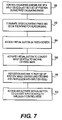
- FIG. 7 an exemplary disclosed embodiment for utilizing an input mechanism both for operating excavating assemblage 34 during an excavating phase, and for controlling steering and propulsion of tractor 12 during a repositioning phase, is diagrammatically illustrated in the form of a flow chart.
- Fully autonomous machine repositioning without operator intervention is difficult and expensive. However, with appropriate automation, an operator may be permitted to exercise control expertly (even though the operator may not be an expert operator). In this exemplary embodiment, a balance between operator control and autonomous operation may be achieved. For example, the machine operator may intervene and interrupt automated control, or the operator may retain control over one or both of steering and propulsion.
- the operator may control the excavating assemblage 34 with an input device (or input devices), such as 56 ( FIG. 2 ), at a first set-up position to excavate during a first excavating phase.
- an input device or input devices
- the right joystick 92 may control two functions of the excavating assemblage 34 and the left joystick 90 may control two other functions of the excavating assemblage 34 .
- the right joystick 92 may control swing mechanism 36 and stick 40
- the left joystick 90 may control boom 38 and bucket 42 .
- the combinations and permutations by which the joysticks 90 , 92 may be programmed may vary.
- the operator may have terminated the first excavating phase and initiated automated preparation for repositioning to the next set-up position for continued excavating.
- the machine may be at some point in the process illustrated in FIG. 6 in preparation for repositioning.
- the operator may access a virtual button located on a touch screen display, at step 304 , which may be a virtual button on the input/display device 54 illustrated in FIG. 2 .
- the operator may activate the virtual button to convert the input device (or input devices) to machine control mode.
- right and left joysticks comprise the input devices, one joystick may control propulsion and the other joystick may control steering.
- a single joystick may be converted such that, for example, forward and backward movement of the joystick controls propulsion (or engine speed) and side to side movement controls steering.
- the machine is repositioned to the next set-up position while the operator controls steering and propulsion via the input device or devices.
- the operator may retain control of those functions over which the operator needs to maintain control. For example, the operator may retain control of a “go forward” command so that the machine does not move unless the operator initiates the command.
- the controller may assist an operator initiated “stop” command.
- autonomous control and operator control act in synergy. The operator may remain facing toward the rear of the machine without the necessity of gaining access to the steering-wheel 72 and pedal 70 .
- the operator at step 310 , may access a virtual button to convert the input device or devices back to implement control mode for controlling the excavating assemblage 34 .
- Control module 52 may include a processor and memory as known in the art.
- the memory may store one or more routines, which could be software programs, for controlling the excavating assemblage 34 as well as other machine components.
- the memory may store routines for controlling the machine during automated preparation for repositioning mode.
- Control module 52 may be configured to receive information from various input devices and from various sensors that may be associated with the excavating assemblage 34 or other machine components. For example, in connection with operation of excavating assemblage 34 , various angle sensors or cylinder position sensors (not shown) may be included for determining the position of various cooperating components and enabling calculation of trench depth.
- FIG. 8 discloses a fully automated process according to an exemplary disclosed embodiment.
- the operator may be in a current trenching phase at a first set-up position.
- the machine may be controlled to excavate a proposed trench with, for example, a backhoe loader 10 . Since the proposed trench will be presumed to have a design length substantially greater than the extent to which the excavating assemblage 34 of the backhoe loader 10 can excavate from a single set-up position, it will be necessary to reposition the tractor 12 , perhaps multiple times, in order to complete a continuous excavation to the design length.
- the current trenching phase may come to an end at step 402 . Then, the operator may be ready to move the tractor forward to a new set-up position in order to begin the next trenching phase.
- the operator initiates a repositioning phase.
- the repositioning phase may be initiated by moving a physical switch or lever, for example.
- the repositioning phase may be initiated by appropriately activating a virtual button on a touch screen display, such as input/display device 54 ( FIG. 2 ). It will be recognized by those having skill in the art that these are merely examples of activating expedients, and that any other known expedient for initiating a programmed operation may be employed.
- a series of events may then take place to reposition the tractor 12 to a new set-up position.
- the engine speed may be reduced.
- Engine speed during an excavating phase may be relatively high in order to support the hydraulic system and the various hydraulic components that drive the excavating assemblage 34 , for example. However, engine speed need not be nearly so high for non-excavating functions, such as those that take place during a repositioning phase.
- Engine speed may be reduced as, or just before, the excavating assemblage 34 is moved to stowed position preparatory to repositioning. Alternatively, or additionally, engine speed may be reduced after the excavating assemblage 34 is moved to stowed position and as the loader bucket 21 is lifted and/or the stabilizers 28 are retracted.
- the excavating assemblage 34 may be moved to a stowed position out of the trench 74 and clear of ground contact.
- bucket 42 may be curled relative to stick 40
- the stick 40 and bucket 42 may be pivoted into close proximity to the boom 38
- the entire assemblage may be centered relative to the tractor 12 by the swing assembly 36 .
- the loader bucket 21 may be lifted from ground contact and stabilizers 28 may be retracted from ground contact. Movement of loader bucket 21 and stabilizers 28 may take place sequentially, simultaneously, or partly sequentially and partly simultaneously. This lifting of the loader bucket and retracting of the stabilizers allow the ground transportation wheels 14 , 16 (or other ground transportation expedients such as tracks) to then fully support the tractor 12 in preparation for movement to the next set-up position.
- Travel mode is entered by reducing engine speed further down to, for example, a low idle, allowing the transmission 61 to be smoothly placed in gear. After a slight delay encountered while the transmission 61 moves into an appropriate gear, engine 60 speed may increase somewhat in order to move the tractor 12 forward.
- the series of activities from the time the repositioning phase is initiated until just before the tractor 12 begins to move forward may be designated as an automated preparation for repositioning mode (see FIG. 6 , for example).
- the activities including stowing the excavating assemblage 34 , removing the loader bucket 21 from ground contact, retracting the stabilizers 28 , reducing engine speed, and engaging a transmission gear appropriate for repositioning may all occur automatically, without manual intervention by the machine operator.
- the travel distance during a machine repositioning phase may be determined. This determination may occur at any number of points in time. For example, as illustrated in FIG. 8 , this determination may occur at some time after entry into travel mode. As indicated at step 414 in FIG. 8 , travel distance may be determined, and this determination may either be by way of a recommendation by a suitable algorithm (see the discussion relevant to the embodiment illustrated in FIG. 5 ), or by operator selection.
- the tractor 12 may move from the current set-up position toward the next set-up position.
- the control system 50 may be programmed for semi-automation.
- the operator may manipulate one or more joysticks, or one or more suitable pedals, to command forward movement of the machine.
- either or both of the steering and propulsion of the tractor 12 may be controlled by the operator through, for example, right joystick 92 and/or left joystick 90 .
- Steering and propulsion of the tractor 12 via joystick control may be by one or more joysticks that may be converted from implement control mode to machine movement control mode in accordance with the discussion of the embodiment illustrated in FIG. 7 .
- an operator need not change positions, such as by rotating seat 78 , for example, and may use the same joystick or joysticks that are used to control the excavating assemblage by converting to steering and propulsion control mode. Control of steering and/or propulsion may thus remain with the operator. The operator may then suitably intervene to avoid any site obstructions or otherwise address safety concerns. Additionally, the operator maintains the sense of being in control, even though some functions are automated.
- tractor 12 approaches a programmed or desired distance for a new set-up location.
- the machine may slow down regardless of operator input.
- This semi-automatic control gives the operator the control that may be needed while ensuring that the target distance is accurately achieved. If the operator, inadvertently or otherwise, attempts to exceed the target distance, the operator's input is overridden. Thus the machine stops at the target distance.
- This strict control of the repositioning or hop distance permits maximizing the distance between excavating phases, while still ensuring a smooth trench bottom and minimizing the time and effort that must be expended on the excavating operation.
- Control module 52 may determine when the machine has traveled the target distance to the new set-up position. Any suitable distance determining expedient, such as a GPS tracking system or an inertial tracking system, for example, may be employed to determine how far the machine has moved.
- the tractor 12 may come to a smooth stop at the designated new set-up location, such as at a recommended efficient permissible distance from the first set-up position as determined in accordance with the procedure described in connection with FIG. 5 . Once tractor 12 has come to a stop, transition from repositioning phase to excavating phase may begin.
- the engine speed may be increased to support lowering of the loader bucket 21 and stabilizers 28 .
- the loader bucket 21 may be forced into ground contact and the stabilizers 28 may be deployed, all with sufficient force to raise and level the machine into a position supported by the loader bucket 21 and the stabilizers 28 . In this position, the ground transportation wheels 14 , 16 may be entirely out of contact with the ground (see FIG. 4 ).
- the engine 60 may increase speed to the level that supports an excavating phase.
- the excavating assemblage 34 may be moved from the stowed position to a position ready to resume trenching. Trenching may then be continued from the new set-up position within the working limits of the excavating assemblage or until the trench is finished.
- the process schematically illustrated in FIG. 8 and described above is an exemplary embodiment which may vary.
- one or more actions identified in connection with FIG. 8 may be omitted in a given situation.
- the semi-automatic mode of operation may be applicable in situations where machine functions, such as steering and propulsion, are performed by input devices other than joysticks.
- the control system may be configured such that the operator may initiate forward movement with a pedal, such as pedal 70 in FIG. 1 , and the controller may stop the machine forward movement at a desired or pre-programmed position.
- This semi-automatic control may be used either during a hop or repositioning phase or during other forward machine movement.
- semi-automatic control wherein the operator initiates movement and a machine controller stops movement, is applicable to machines other than backhoe loaders, such as, for example, a hydraulic excavator.
- Delays and inefficiencies are an ordinary part of an excavating operation requiring a plurality of set-up positions for its completion.
- various expedients including automation, such delays and inefficiencies may be avoided.
- an efficient, permissible distance for machine repositioning between excavating phases in a trenching operation may be calculated and recommended under complete automation in order to enhance efficiency.
- certain preparation activities that occur upon termination of an excavating phase and prior to machine repositioning may be automated.
- an implement control input device or input devices may be suitably converted to a mode for controlling machine steering and propulsion in order, among other things, to obviate the need for repositioning the operator seat.
- the repositioning distance a machine must move from one set-up position to the next over the course of an extended trench excavating operation ordinarily is left to operator judgment and discretion. Because an efficient permissible distance for repositioning may be calculated and recommended to the operator based on numerous measured variables, reliance for best, maximum, and/or optimum distance to move between one set-up position and the next need not be left to operator discretion based on estimations. Since a consistent and efficient distance may be immediately available to the operator and actually programmed into the machine, the trench may be more efficiently excavated and, particularly with a trench of significant length, substantial time may be saved.
- the actions which ordinarily take place in preparation for repositioning between set-up positions may be individually initiated by the machine operator. Aside from being one more fatigue factor, the efficiency and consistency of this series of actions may vary considerably, depending on the skill and experience of the operator. By automating the preparation for repositioning procedure, operator fatigue is reduced and efficiency and consistency of overall machine operation is enhanced. A novice operator may be able to operator a machine with the efficiency of an expert.
- the machine operator may conveniently access an on-board touch screen display and activate a virtual button to convert an input device or devices from excavating assemblage control to steering and propulsion control, and vice versa, the operator need not move back and forth between the controls for the excavating assemblage (at the machine rear) and the controls for steering and propulsion (at the machine front).
- the touch screen display and instant conversion from one mode to another eliminates operator fatigue factors that are unavoidably a part of heavy equipment operation.
- Employing a touch screen for converting an input device or devices from one mode to another constitutes a safety feature since inadvertent conversion from one mode to another is more improbable than it would be where a switch or button, closely associated with the input device (such as a joystick) is employed.
Abstract
Description
Claims (7)
Priority Applications (2)
| Application Number | Priority Date | Filing Date | Title |
|---|---|---|---|
| US11/606,166 US7726048B2 (en) | 2006-11-30 | 2006-11-30 | Automated machine repositioning in an excavating operation |
| PCT/US2007/023193 WO2008066650A1 (en) | 2006-11-30 | 2007-11-02 | Automated machine repositioning in an excavating operation |
Applications Claiming Priority (1)
| Application Number | Priority Date | Filing Date | Title |
|---|---|---|---|
| US11/606,166 US7726048B2 (en) | 2006-11-30 | 2006-11-30 | Automated machine repositioning in an excavating operation |
Publications (2)
| Publication Number | Publication Date |
|---|---|
| US20080127531A1 US20080127531A1 (en) | 2008-06-05 |
| US7726048B2 true US7726048B2 (en) | 2010-06-01 |
Family
ID=39135124
Family Applications (1)
| Application Number | Title | Priority Date | Filing Date |
|---|---|---|---|
| US11/606,166 Expired - Fee Related US7726048B2 (en) | 2006-11-30 | 2006-11-30 | Automated machine repositioning in an excavating operation |
Country Status (2)
| Country | Link |
|---|---|
| US (1) | US7726048B2 (en) |
| WO (1) | WO2008066650A1 (en) |
Cited By (9)
| Publication number | Priority date | Publication date | Assignee | Title |
|---|---|---|---|---|
| US20130045071A1 (en) * | 2011-08-16 | 2013-02-21 | Caterpillar, Inc. | Machine Having Hydraulically Actuated Implement System With Down Force Control, And Method |
| US20130054075A1 (en) * | 2011-08-22 | 2013-02-28 | Deere And Company | Location Control System for Feature Placement |
| US8620533B2 (en) | 2011-08-30 | 2013-12-31 | Harnischfeger Technologies, Inc. | Systems, methods, and devices for controlling a movement of a dipper |
| US9206587B2 (en) | 2012-03-16 | 2015-12-08 | Harnischfeger Technologies, Inc. | Automated control of dipper swing for a shovel |
| US9580883B2 (en) | 2014-08-25 | 2017-02-28 | Cnh Industrial America Llc | System and method for automatically controlling a lift assembly of a work vehicle |
| US10227754B2 (en) | 2011-04-14 | 2019-03-12 | Joy Global Surface Mining Inc | Swing automation for rope shovel |
| US10494788B2 (en) | 2016-11-02 | 2019-12-03 | Clark Equipment Company | System and method for defining a zone of operation for a lift arm |
| US10683638B2 (en) | 2017-09-12 | 2020-06-16 | Cnh Industrial America Llc | System for repositioning a backhoe digger |
| US10982410B2 (en) | 2016-09-08 | 2021-04-20 | Joy Global Surface Mining Inc | System and method for semi-autonomous control of an industrial machine |
Families Citing this family (12)
| Publication number | Priority date | Publication date | Assignee | Title |
|---|---|---|---|---|
| US7753132B2 (en) * | 2006-11-30 | 2010-07-13 | Caterpillar Inc | Preparation for machine repositioning in an excavating operation |
| US8170756B2 (en) * | 2007-08-30 | 2012-05-01 | Caterpillar Inc. | Excavating system utilizing machine-to-machine communication |
| GB2461910B (en) * | 2008-07-17 | 2012-07-18 | Bamford Excavators Ltd | Method of operating an apparatus |
| USD645259S1 (en) | 2009-06-19 | 2011-09-20 | Dsm Ip Assets B.V. | Film sheet for use in antiballistic articles |
| US20110213529A1 (en) * | 2010-02-26 | 2011-09-01 | Caterpillar Inc. | System and method for determing a position on an implement relative to a reference position on a machine |
| GB2522050B (en) * | 2014-01-13 | 2016-12-14 | Jc Bamford Excavators Ltd | A method of operating a material handling machine |
| GB2527795B (en) * | 2014-07-02 | 2019-11-13 | Bamford Excavators Ltd | Automation of a material handling machine digging cycle |
| JP2017043885A (en) * | 2015-08-24 | 2017-03-02 | 株式会社小松製作所 | Wheel loader |
| GB2543334B (en) | 2015-10-15 | 2020-03-11 | Bamford Excavators Ltd | A method for providing an alert |
| JP7291645B2 (en) * | 2020-01-31 | 2023-06-15 | 株式会社小松製作所 | SYSTEM, CONTROL METHOD AND EXCAVATOR FOR PREVENTING ERROR OPERATION OF WORK MACHINE |
| US11877095B2 (en) * | 2020-05-26 | 2024-01-16 | Cnh Industrial America Llc | System and method for automatically controlling a display system for a work vehicle |
| CN113047366B (en) * | 2021-04-08 | 2023-01-17 | 江苏徐工工程机械研究院有限公司 | Control method, device and system of backhoe loader and backhoe loader |
Citations (73)
| Publication number | Priority date | Publication date | Assignee | Title |
|---|---|---|---|---|
| US3339763A (en) | 1966-10-14 | 1967-09-05 | Univ Oklahoma State | Automatic back hoe control system |
| US4015729A (en) | 1976-01-02 | 1977-04-05 | J. I. Case Company | Automatic control system for backhoe |
| US4140144A (en) | 1975-12-15 | 1979-02-20 | Massey-Ferguson Inc. | Method of providing interchangeable valve control mechanisms |
| US4288196A (en) | 1979-06-14 | 1981-09-08 | Sutton Ii James O | Computer controlled backhoe |
| US4531883A (en) | 1982-12-08 | 1985-07-30 | Wain-Roy, Inc. | Backhoe stabilizer system |
| US4677555A (en) | 1983-11-28 | 1987-06-30 | Syndicat National Des Entreprises De Drainage | Method and equipment for automatic guidance of earthmoving machines and especially machines for laying drainage elements |
| US4869337A (en) | 1987-10-15 | 1989-09-26 | Clark Equipment Company | Backhoe creep lever mechanism for an excavating vehicle |
| US5065326A (en) | 1989-08-17 | 1991-11-12 | Caterpillar, Inc. | Automatic excavation control system and method |
| US5138756A (en) | 1989-12-08 | 1992-08-18 | Ford New Holland, Inc. | Method of converting backhoe controls |
| JPH05297942A (en) | 1992-04-20 | 1993-11-12 | Fujita Corp | Automatic transfer system for construction work |
| US5347448A (en) | 1992-11-25 | 1994-09-13 | Samsung Heavy Industries Co., Ltd. | Multiprocessor system for hydraulic excavator |
| EP0616275A2 (en) | 1993-03-16 | 1994-09-21 | Francis M. Fulton | Adaptive control man-augmentation system for a suspended work station |
| US5528843A (en) | 1994-08-18 | 1996-06-25 | Caterpillar Inc. | Control system for automatically controlling a work implement of an earthworking machine to capture material |
| US5546093A (en) | 1994-01-04 | 1996-08-13 | Caterpillar Inc. | System and method for providing navigation signals to an earthmoving or construction machine |
| US5699247A (en) | 1990-07-25 | 1997-12-16 | Shin Caterpillar Mitsubishi, Ltd. | Fuzzy control system and method for hydraulic backhoe or like excavator |
| US5704429A (en) * | 1996-03-30 | 1998-01-06 | Samsung Heavy Industries Co., Ltd. | Control system of an excavator |
| US5806016A (en) | 1996-03-28 | 1998-09-08 | Caterpillar Inc. | Method for determining the course of a machine |
| US5854988A (en) | 1996-06-05 | 1998-12-29 | Topcon Laser Systems, Inc. | Method for controlling an excavator |
| US6061617A (en) * | 1997-10-21 | 2000-05-09 | Case Corporation | Adaptable controller for work vehicle attachments |
| US6062317A (en) | 1999-09-03 | 2000-05-16 | Caterpillar Inc. | Method and apparatus for controlling the direction of travel of an earthworking machine |
| US6076030A (en) | 1998-10-14 | 2000-06-13 | Carnegie Mellon University | Learning system and method for optimizing control of autonomous earthmoving machinery |
| US6108949A (en) | 1997-12-19 | 2000-08-29 | Carnegie Mellon University | Method and apparatus for determining an excavation strategy |
| US6131062A (en) | 1999-01-21 | 2000-10-10 | Case Corporation | Apparatus and method for preventing an automatic operation sequence in a work vehicle |
| US6167336A (en) | 1998-05-18 | 2000-12-26 | Carnegie Mellon University | Method and apparatus for determining an excavation strategy for a front-end loader |
| US6223110B1 (en) | 1997-12-19 | 2001-04-24 | Carnegie Mellon University | Software architecture for autonomous earthmoving machinery |
| US6234254B1 (en) | 1999-03-29 | 2001-05-22 | Caterpillar Inc. | Apparatus and method for controlling the efficiency of the work cycle associated with an earthworking machine |
| US6247538B1 (en) | 1996-09-13 | 2001-06-19 | Komatsu Ltd. | Automatic excavator, automatic excavation method and automatic loading method |
| US6292729B2 (en) | 1999-04-14 | 2001-09-18 | Deere & Company | Vehicle function management system |
| US6354023B1 (en) | 1998-12-15 | 2002-03-12 | Bombardier Inc. | Snow groomers and control system therefor |
| US6363632B1 (en) | 1998-10-09 | 2002-04-02 | Carnegie Mellon University | System for autonomous excavation and truck loading |
| US6371214B1 (en) | 1999-06-11 | 2002-04-16 | Caterpillar Inc. | Methods for automating work machine functions |
| US6418364B1 (en) | 2000-12-13 | 2002-07-09 | Caterpillar Inc. | Method for determining a position and heading of a work machine |
| US6430850B1 (en) | 2000-07-25 | 2002-08-13 | Deere & Company | Seat switch activated pump |
| US6510628B1 (en) | 2001-10-31 | 2003-01-28 | Caterpillar Inc | Method and apparatus for determining a contact force of a work tool |
| US6539294B1 (en) * | 1998-02-13 | 2003-03-25 | Komatsu Ltd. | Vehicle guidance system for avoiding obstacles stored in memory |
| US6542789B2 (en) | 1998-12-22 | 2003-04-01 | Caterpillar Inc | Tool recognition and control system for a work machine |
| US6604305B2 (en) | 2001-09-28 | 2003-08-12 | Caterpillar Inc | Method and apparatus for controlling an extendable stick on a work machine |
| US6609315B1 (en) | 2002-10-31 | 2003-08-26 | Deere & Company | Automatic backhoe tool orientation control |
| US6643577B1 (en) | 2002-08-22 | 2003-11-04 | Caterpillar Inc | Operator control station and method for a work machine having more than one function |
| US6643576B1 (en) | 2000-11-15 | 2003-11-04 | Integrinautics Corporation | Rapid adjustment of trajectories for land vehicles |
| US6658767B2 (en) | 2000-10-23 | 2003-12-09 | Mastenbroek Ltd. | Trenching method and apparatus |
| US6691010B1 (en) | 2000-11-15 | 2004-02-10 | Caterpillar Inc | Method for developing an algorithm to efficiently control an autonomous excavating linkage |
| US6701239B2 (en) | 2002-04-10 | 2004-03-02 | Caterpillar Inc | Method and apparatus for controlling the updating of a machine database |
| US6718244B2 (en) | 2001-12-28 | 2004-04-06 | Case, Llc | Skid steer vehicle having an anti-diving system |
| US6725142B2 (en) | 2002-07-09 | 2004-04-20 | Caterpillar Inc | Control system for a work machine digging assembly |
| US6732458B2 (en) | 1998-03-18 | 2004-05-11 | Hitachi Construction Machinery Co., Ltd. | Automatically operated shovel and stone crushing system comprising same |
| US6736216B2 (en) | 2000-05-05 | 2004-05-18 | Leica Geosystems Gr, Llc | Laser-guided construction equipment |
| US6757994B1 (en) | 2003-04-11 | 2004-07-06 | Deere & Company | Automatic tool orientation control for backhoe with extendable dipperstick |
| US6763619B2 (en) | 2002-10-31 | 2004-07-20 | Deere & Company | Automatic loader bucket orientation control |
| US6813557B2 (en) * | 2003-03-27 | 2004-11-02 | Deere & Company | Method and system for controlling a vehicle having multiple control modes |
| US6819993B2 (en) | 2002-12-12 | 2004-11-16 | Caterpillar Inc | System for estimating a linkage position |
| US6851495B2 (en) | 2001-10-19 | 2005-02-08 | Deere & Co. | Speed control for utility vehicle operable from rearward-facing seat |
| US6879899B2 (en) | 2002-12-12 | 2005-04-12 | Caterpillar Inc | Method and system for automatic bucket loading |
| EP1526221A1 (en) | 2003-10-20 | 2005-04-27 | CNH Italia S.p.A. | Work vehicle stabilizer. |
| US6907336B2 (en) | 2003-03-31 | 2005-06-14 | Deere & Company | Method and system for efficiently traversing an area with a work vehicle |
| US6915599B2 (en) | 2003-08-25 | 2005-07-12 | Caterpillar Inc | System for controlling movement of a work machine arm |
| US6934615B2 (en) | 2003-03-31 | 2005-08-23 | Deere & Company | Method and system for determining an efficient vehicle path |
| US20050209759A1 (en) | 2004-03-22 | 2005-09-22 | Volvo Construction Equipment Holding Sweden Ab | Method of controlling travel of construction heavy equipment with electronic joysticks |
| GB2412362A (en) | 2002-08-22 | 2005-09-28 | Caterpillar Inc | Method for a work machine having more than one function |
| US6954999B1 (en) | 2004-12-13 | 2005-10-18 | Trimble Navigation Limited | Trencher guidance via GPS |
| US6980895B2 (en) | 2001-12-03 | 2005-12-27 | Cnh America Llc | Electronic control system for agricultural vehicle |
| US20060021819A1 (en) | 2004-07-30 | 2006-02-02 | Caterpillar Inc. | Work machine tool control console |
| US20060034535A1 (en) | 2004-08-10 | 2006-02-16 | Koch Roger D | Method and apparatus for enhancing visibility to a machine operator |
| US7007415B2 (en) | 2003-12-18 | 2006-03-07 | Caterpillar Inc. | Method and system of controlling a work tool |
| US7010367B2 (en) | 2003-10-16 | 2006-03-07 | Caterpillar Inc. | Operator interface for a work machine |
| US7010425B2 (en) | 2003-03-31 | 2006-03-07 | Deere & Company | Path planner and a method for planning a path of a work vehicle |
| US20060064221A1 (en) | 2004-09-21 | 2006-03-23 | Sporer Mark A | Operator selectable control pattern |
| US7032703B2 (en) | 2002-06-17 | 2006-04-25 | Caterpillar Inc. | Operator control station for controlling different work machines |
| EP1650359A2 (en) | 2004-10-21 | 2006-04-26 | Deere & Company | Multiple mode operational system for work vehicle braking or propulsion |
| US20060089773A1 (en) | 2004-10-21 | 2006-04-27 | Hendron Scott S | Multiple mode operational system for work vehicle propulsion |
| US20060090379A1 (en) | 2004-09-01 | 2006-05-04 | Ken Furem | Autonomous loading shovel system |
| US20060095186A1 (en) | 2004-10-29 | 2006-05-04 | Deere & Company, A Delaware Corporation | Multiple mode operational system for work vehicle braking |
| US20060137931A1 (en) | 2004-12-23 | 2006-06-29 | Caterpillar Inc. | Steering system with joystick mounted controls |
-
2006
- 2006-11-30 US US11/606,166 patent/US7726048B2/en not_active Expired - Fee Related
-
2007
- 2007-11-02 WO PCT/US2007/023193 patent/WO2008066650A1/en active Application Filing
Patent Citations (74)
| Publication number | Priority date | Publication date | Assignee | Title |
|---|---|---|---|---|
| US3339763A (en) | 1966-10-14 | 1967-09-05 | Univ Oklahoma State | Automatic back hoe control system |
| US4140144A (en) | 1975-12-15 | 1979-02-20 | Massey-Ferguson Inc. | Method of providing interchangeable valve control mechanisms |
| US4015729A (en) | 1976-01-02 | 1977-04-05 | J. I. Case Company | Automatic control system for backhoe |
| US4288196A (en) | 1979-06-14 | 1981-09-08 | Sutton Ii James O | Computer controlled backhoe |
| US4531883A (en) | 1982-12-08 | 1985-07-30 | Wain-Roy, Inc. | Backhoe stabilizer system |
| US4677555A (en) | 1983-11-28 | 1987-06-30 | Syndicat National Des Entreprises De Drainage | Method and equipment for automatic guidance of earthmoving machines and especially machines for laying drainage elements |
| US4869337A (en) | 1987-10-15 | 1989-09-26 | Clark Equipment Company | Backhoe creep lever mechanism for an excavating vehicle |
| US5065326A (en) | 1989-08-17 | 1991-11-12 | Caterpillar, Inc. | Automatic excavation control system and method |
| US5138756A (en) | 1989-12-08 | 1992-08-18 | Ford New Holland, Inc. | Method of converting backhoe controls |
| US5699247A (en) | 1990-07-25 | 1997-12-16 | Shin Caterpillar Mitsubishi, Ltd. | Fuzzy control system and method for hydraulic backhoe or like excavator |
| JPH05297942A (en) | 1992-04-20 | 1993-11-12 | Fujita Corp | Automatic transfer system for construction work |
| US5347448A (en) | 1992-11-25 | 1994-09-13 | Samsung Heavy Industries Co., Ltd. | Multiprocessor system for hydraulic excavator |
| EP0616275A2 (en) | 1993-03-16 | 1994-09-21 | Francis M. Fulton | Adaptive control man-augmentation system for a suspended work station |
| US5546093A (en) | 1994-01-04 | 1996-08-13 | Caterpillar Inc. | System and method for providing navigation signals to an earthmoving or construction machine |
| US5528843A (en) | 1994-08-18 | 1996-06-25 | Caterpillar Inc. | Control system for automatically controlling a work implement of an earthworking machine to capture material |
| US5806016A (en) | 1996-03-28 | 1998-09-08 | Caterpillar Inc. | Method for determining the course of a machine |
| US5704429A (en) * | 1996-03-30 | 1998-01-06 | Samsung Heavy Industries Co., Ltd. | Control system of an excavator |
| US5854988A (en) | 1996-06-05 | 1998-12-29 | Topcon Laser Systems, Inc. | Method for controlling an excavator |
| US6247538B1 (en) | 1996-09-13 | 2001-06-19 | Komatsu Ltd. | Automatic excavator, automatic excavation method and automatic loading method |
| US6061617A (en) * | 1997-10-21 | 2000-05-09 | Case Corporation | Adaptable controller for work vehicle attachments |
| US6108949A (en) | 1997-12-19 | 2000-08-29 | Carnegie Mellon University | Method and apparatus for determining an excavation strategy |
| US6223110B1 (en) | 1997-12-19 | 2001-04-24 | Carnegie Mellon University | Software architecture for autonomous earthmoving machinery |
| US6539294B1 (en) * | 1998-02-13 | 2003-03-25 | Komatsu Ltd. | Vehicle guidance system for avoiding obstacles stored in memory |
| US6732458B2 (en) | 1998-03-18 | 2004-05-11 | Hitachi Construction Machinery Co., Ltd. | Automatically operated shovel and stone crushing system comprising same |
| US6167336A (en) | 1998-05-18 | 2000-12-26 | Carnegie Mellon University | Method and apparatus for determining an excavation strategy for a front-end loader |
| US6363632B1 (en) | 1998-10-09 | 2002-04-02 | Carnegie Mellon University | System for autonomous excavation and truck loading |
| US6076030A (en) | 1998-10-14 | 2000-06-13 | Carnegie Mellon University | Learning system and method for optimizing control of autonomous earthmoving machinery |
| US6354023B1 (en) | 1998-12-15 | 2002-03-12 | Bombardier Inc. | Snow groomers and control system therefor |
| US6542789B2 (en) | 1998-12-22 | 2003-04-01 | Caterpillar Inc | Tool recognition and control system for a work machine |
| US6131062A (en) | 1999-01-21 | 2000-10-10 | Case Corporation | Apparatus and method for preventing an automatic operation sequence in a work vehicle |
| US6234254B1 (en) | 1999-03-29 | 2001-05-22 | Caterpillar Inc. | Apparatus and method for controlling the efficiency of the work cycle associated with an earthworking machine |
| US6292729B2 (en) | 1999-04-14 | 2001-09-18 | Deere & Company | Vehicle function management system |
| US6371214B1 (en) | 1999-06-11 | 2002-04-16 | Caterpillar Inc. | Methods for automating work machine functions |
| US6062317A (en) | 1999-09-03 | 2000-05-16 | Caterpillar Inc. | Method and apparatus for controlling the direction of travel of an earthworking machine |
| US6736216B2 (en) | 2000-05-05 | 2004-05-18 | Leica Geosystems Gr, Llc | Laser-guided construction equipment |
| US6430850B1 (en) | 2000-07-25 | 2002-08-13 | Deere & Company | Seat switch activated pump |
| US6658767B2 (en) | 2000-10-23 | 2003-12-09 | Mastenbroek Ltd. | Trenching method and apparatus |
| US6691010B1 (en) | 2000-11-15 | 2004-02-10 | Caterpillar Inc | Method for developing an algorithm to efficiently control an autonomous excavating linkage |
| US6643576B1 (en) | 2000-11-15 | 2003-11-04 | Integrinautics Corporation | Rapid adjustment of trajectories for land vehicles |
| US6418364B1 (en) | 2000-12-13 | 2002-07-09 | Caterpillar Inc. | Method for determining a position and heading of a work machine |
| US6604305B2 (en) | 2001-09-28 | 2003-08-12 | Caterpillar Inc | Method and apparatus for controlling an extendable stick on a work machine |
| US6851495B2 (en) | 2001-10-19 | 2005-02-08 | Deere & Co. | Speed control for utility vehicle operable from rearward-facing seat |
| US6510628B1 (en) | 2001-10-31 | 2003-01-28 | Caterpillar Inc | Method and apparatus for determining a contact force of a work tool |
| US6980895B2 (en) | 2001-12-03 | 2005-12-27 | Cnh America Llc | Electronic control system for agricultural vehicle |
| US6718244B2 (en) | 2001-12-28 | 2004-04-06 | Case, Llc | Skid steer vehicle having an anti-diving system |
| US6701239B2 (en) | 2002-04-10 | 2004-03-02 | Caterpillar Inc | Method and apparatus for controlling the updating of a machine database |
| US7032703B2 (en) | 2002-06-17 | 2006-04-25 | Caterpillar Inc. | Operator control station for controlling different work machines |
| US6725142B2 (en) | 2002-07-09 | 2004-04-20 | Caterpillar Inc | Control system for a work machine digging assembly |
| US6643577B1 (en) | 2002-08-22 | 2003-11-04 | Caterpillar Inc | Operator control station and method for a work machine having more than one function |
| GB2392147A (en) | 2002-08-22 | 2004-02-25 | Caterpillar Inc | Operator control station and method for a work machine having hybrid functions |
| GB2412362A (en) | 2002-08-22 | 2005-09-28 | Caterpillar Inc | Method for a work machine having more than one function |
| US6609315B1 (en) | 2002-10-31 | 2003-08-26 | Deere & Company | Automatic backhoe tool orientation control |
| US6763619B2 (en) | 2002-10-31 | 2004-07-20 | Deere & Company | Automatic loader bucket orientation control |
| US6819993B2 (en) | 2002-12-12 | 2004-11-16 | Caterpillar Inc | System for estimating a linkage position |
| US6879899B2 (en) | 2002-12-12 | 2005-04-12 | Caterpillar Inc | Method and system for automatic bucket loading |
| US6813557B2 (en) * | 2003-03-27 | 2004-11-02 | Deere & Company | Method and system for controlling a vehicle having multiple control modes |
| US6934615B2 (en) | 2003-03-31 | 2005-08-23 | Deere & Company | Method and system for determining an efficient vehicle path |
| US6907336B2 (en) | 2003-03-31 | 2005-06-14 | Deere & Company | Method and system for efficiently traversing an area with a work vehicle |
| US7010425B2 (en) | 2003-03-31 | 2006-03-07 | Deere & Company | Path planner and a method for planning a path of a work vehicle |
| US6757994B1 (en) | 2003-04-11 | 2004-07-06 | Deere & Company | Automatic tool orientation control for backhoe with extendable dipperstick |
| US6915599B2 (en) | 2003-08-25 | 2005-07-12 | Caterpillar Inc | System for controlling movement of a work machine arm |
| US7010367B2 (en) | 2003-10-16 | 2006-03-07 | Caterpillar Inc. | Operator interface for a work machine |
| EP1526221A1 (en) | 2003-10-20 | 2005-04-27 | CNH Italia S.p.A. | Work vehicle stabilizer. |
| US7007415B2 (en) | 2003-12-18 | 2006-03-07 | Caterpillar Inc. | Method and system of controlling a work tool |
| US20050209759A1 (en) | 2004-03-22 | 2005-09-22 | Volvo Construction Equipment Holding Sweden Ab | Method of controlling travel of construction heavy equipment with electronic joysticks |
| US20060021819A1 (en) | 2004-07-30 | 2006-02-02 | Caterpillar Inc. | Work machine tool control console |
| US20060034535A1 (en) | 2004-08-10 | 2006-02-16 | Koch Roger D | Method and apparatus for enhancing visibility to a machine operator |
| US20060090379A1 (en) | 2004-09-01 | 2006-05-04 | Ken Furem | Autonomous loading shovel system |
| US20060064221A1 (en) | 2004-09-21 | 2006-03-23 | Sporer Mark A | Operator selectable control pattern |
| EP1650359A2 (en) | 2004-10-21 | 2006-04-26 | Deere & Company | Multiple mode operational system for work vehicle braking or propulsion |
| US20060089773A1 (en) | 2004-10-21 | 2006-04-27 | Hendron Scott S | Multiple mode operational system for work vehicle propulsion |
| US20060095186A1 (en) | 2004-10-29 | 2006-05-04 | Deere & Company, A Delaware Corporation | Multiple mode operational system for work vehicle braking |
| US6954999B1 (en) | 2004-12-13 | 2005-10-18 | Trimble Navigation Limited | Trencher guidance via GPS |
| US20060137931A1 (en) | 2004-12-23 | 2006-06-29 | Caterpillar Inc. | Steering system with joystick mounted controls |
Cited By (15)
| Publication number | Priority date | Publication date | Assignee | Title |
|---|---|---|---|---|
| US11028560B2 (en) | 2011-04-14 | 2021-06-08 | Joy Global Surface Mining Inc | Swing automation for rope shovel |
| US10227754B2 (en) | 2011-04-14 | 2019-03-12 | Joy Global Surface Mining Inc | Swing automation for rope shovel |
| US8858151B2 (en) * | 2011-08-16 | 2014-10-14 | Caterpillar Inc. | Machine having hydraulically actuated implement system with down force control, and method |
| US20130045071A1 (en) * | 2011-08-16 | 2013-02-21 | Caterpillar, Inc. | Machine Having Hydraulically Actuated Implement System With Down Force Control, And Method |
| US20130054075A1 (en) * | 2011-08-22 | 2013-02-28 | Deere And Company | Location Control System for Feature Placement |
| US8620533B2 (en) | 2011-08-30 | 2013-12-31 | Harnischfeger Technologies, Inc. | Systems, methods, and devices for controlling a movement of a dipper |
| US8688334B2 (en) | 2011-08-30 | 2014-04-01 | Harnischfeger Technologies, Inc. | Systems, methods, and devices for controlling a movement of a dipper |
| US9206587B2 (en) | 2012-03-16 | 2015-12-08 | Harnischfeger Technologies, Inc. | Automated control of dipper swing for a shovel |
| US9745721B2 (en) | 2012-03-16 | 2017-08-29 | Harnischfeger Technologies, Inc. | Automated control of dipper swing for a shovel |
| US11761172B2 (en) | 2012-03-16 | 2023-09-19 | Joy Global Surface Mining Inc | Automated control of dipper swing for a shovel |
| US10655301B2 (en) | 2012-03-16 | 2020-05-19 | Joy Global Surface Mining Inc | Automated control of dipper swing for a shovel |
| US9580883B2 (en) | 2014-08-25 | 2017-02-28 | Cnh Industrial America Llc | System and method for automatically controlling a lift assembly of a work vehicle |
| US10982410B2 (en) | 2016-09-08 | 2021-04-20 | Joy Global Surface Mining Inc | System and method for semi-autonomous control of an industrial machine |
| US10494788B2 (en) | 2016-11-02 | 2019-12-03 | Clark Equipment Company | System and method for defining a zone of operation for a lift arm |
| US10683638B2 (en) | 2017-09-12 | 2020-06-16 | Cnh Industrial America Llc | System for repositioning a backhoe digger |
Also Published As
| Publication number | Publication date |
|---|---|
| WO2008066650A1 (en) | 2008-06-05 |
| US20080127531A1 (en) | 2008-06-05 |
Similar Documents
| Publication | Publication Date | Title |
|---|---|---|
| US7726048B2 (en) | Automated machine repositioning in an excavating operation | |
| US7634863B2 (en) | Repositioning assist for an excavating operation | |
| US7753132B2 (en) | Preparation for machine repositioning in an excavating operation | |
| US7694442B2 (en) | Recommending a machine repositioning distance in an excavating operation | |
| JP3534979B2 (en) | Excavator control method | |
| EP2980317A1 (en) | Multiple control patterns for hydraulically operated machines with hand and foot controls | |
| KR100676291B1 (en) | Control equipment for working machine | |
| US11879234B2 (en) | Work vehicle | |
| JPH10212740A (en) | Automatic excavating method for hydraulic shovel | |
| GB2518236A (en) | Training apparatus | |
| EP2894264B1 (en) | A method of operating a material handling machine | |
| US9617710B2 (en) | Work vehicle and method for controlling work vehicle | |
| JP4140940B2 (en) | Excavator loading machine work machine controller | |
| JP4076200B2 (en) | Excavator loading machine work machine controller | |
| JP7286287B2 (en) | Work machine display system and its control method | |
| US7627966B2 (en) | Off-fall control for a trenching operation | |
| JP4111415B2 (en) | Excavator loading machine work machine controller | |
| CN112204198B (en) | Display system for working machine and control method thereof | |
| JPS63194030A (en) | Controlling method and apparatus for service machine of power shovel | |
| WO2022244830A1 (en) | Control system and control method for loading machine | |
| JP7197315B2 (en) | Wheel loader display system and its control method | |
| JPS6243014B2 (en) | ||
| KR20240038591A (en) | Method for controlling work in agricultural tractor | |
| JPH0689552B2 (en) | Automatic excavator for loading machines |
Legal Events
| Date | Code | Title | Description |
|---|---|---|---|
| AS | Assignment |
Owner name: CATERPILLAR INC., ILLINOIS Free format text: ASSIGNMENT OF ASSIGNORS INTEREST;ASSIGNORS:STANEK, DANIEL;KOCH, ROGER D.;ALIG, JEFFREY S.;AND OTHERS;REEL/FRAME:018812/0990 Effective date: 20061129 Owner name: CATERPILLAR INC.,ILLINOIS Free format text: ASSIGNMENT OF ASSIGNORS INTEREST;ASSIGNORS:STANEK, DANIEL;KOCH, ROGER D.;ALIG, JEFFREY S.;AND OTHERS;REEL/FRAME:018812/0990 Effective date: 20061129 |
|
| STCF | Information on status: patent grant |
Free format text: PATENTED CASE |
|
| FPAY | Fee payment |
Year of fee payment: 4 |
|
| MAFP | Maintenance fee payment |
Free format text: PAYMENT OF MAINTENANCE FEE, 8TH YEAR, LARGE ENTITY (ORIGINAL EVENT CODE: M1552) Year of fee payment: 8 |
|
| FEPP | Fee payment procedure |
Free format text: MAINTENANCE FEE REMINDER MAILED (ORIGINAL EVENT CODE: REM.); ENTITY STATUS OF PATENT OWNER: LARGE ENTITY |
|
| LAPS | Lapse for failure to pay maintenance fees |
Free format text: PATENT EXPIRED FOR FAILURE TO PAY MAINTENANCE FEES (ORIGINAL EVENT CODE: EXP.); ENTITY STATUS OF PATENT OWNER: LARGE ENTITY |
|
| STCH | Information on status: patent discontinuation |
Free format text: PATENT EXPIRED DUE TO NONPAYMENT OF MAINTENANCE FEES UNDER 37 CFR 1.362 |
|
| FP | Lapsed due to failure to pay maintenance fee |
Effective date: 20220601 |