US8058875B2 - Detection of ground-laid wire using ultraviolet C-band radiation - Google Patents
Detection of ground-laid wire using ultraviolet C-band radiation Download PDFInfo
- Publication number
- US8058875B2 US8058875B2 US12/538,997 US53899709A US8058875B2 US 8058875 B2 US8058875 B2 US 8058875B2 US 53899709 A US53899709 A US 53899709A US 8058875 B2 US8058875 B2 US 8058875B2
- Authority
- US
- United States
- Prior art keywords
- wire
- ultraviolet
- band
- conductor
- ground
- Prior art date
- Legal status (The legal status is an assumption and is not a legal conclusion. Google has not performed a legal analysis and makes no representation as to the accuracy of the status listed.)
- Active, expires
Links
Images


Classifications
-
- G—PHYSICS
- G01—MEASURING; TESTING
- G01R—MEASURING ELECTRIC VARIABLES; MEASURING MAGNETIC VARIABLES
- G01R31/00—Arrangements for testing electric properties; Arrangements for locating electric faults; Arrangements for electrical testing characterised by what is being tested not provided for elsewhere
- G01R31/08—Locating faults in cables, transmission lines, or networks
- G01R31/081—Locating faults in cables, transmission lines, or networks according to type of conductors
- G01R31/083—Locating faults in cables, transmission lines, or networks according to type of conductors in cables, e.g. underground
-
- G—PHYSICS
- G01—MEASURING; TESTING
- G01R—MEASURING ELECTRIC VARIABLES; MEASURING MAGNETIC VARIABLES
- G01R31/00—Arrangements for testing electric properties; Arrangements for locating electric faults; Arrangements for electrical testing characterised by what is being tested not provided for elsewhere
- G01R31/12—Testing dielectric strength or breakdown voltage ; Testing or monitoring effectiveness or level of insulation, e.g. of a cable or of an apparatus, for example using partial discharge measurements; Electrostatic testing
- G01R31/1218—Testing dielectric strength or breakdown voltage ; Testing or monitoring effectiveness or level of insulation, e.g. of a cable or of an apparatus, for example using partial discharge measurements; Electrostatic testing using optical methods; using charged particle, e.g. electron, beams or X-rays
Definitions
- the inventive techniques and systems generally relate to detecting and tracing wire paths and, in particular, visually detecting ground-laid wire using ultraviolet c-band radiation.
- UV light is electromagnetic radiation with a wavelength shorter than that of visible light, but longer than x-rays.
- UV light includes wavelengths in the range of 100 to 400 nanometers (nm) and energies from 3 to 124 electron-volts.
- UV light is emitted by the Sun, electric arcs, and artificial light sources such as black lights.
- UV sources can cause chemical reactions that cause many substances to glow or fluoresce.
- UV light is beyond visible light, most people are aware of the effects of UV radiation through sunburn. However, the UV spectrum has many other effects, both beneficial and damaging, on human health.
- UV radiation can be classified in a number of ways, including as bands of radiation separated into the following:
- UV A-band 400-320 nm.
- UV B-band 320-280 nm.
- UV C-band 280-200 nm.
- the Sun emits UV A, UV B, and UV C-band radiation; however, the Earth atmosphere's ozone layer absorbs about 98.7% of this radiation, primarily in the UV B and UV C-bands.
- Other natural sources of UV radiation include lightning and fires.
- ordinary glass is partially transparent to UV A-band radiation, but is opaque to shorter UV wavelengths in the UV B and UV C-bands.
- Silica or Quartz glass depending on quality of materials, can be transparent to even UV C-band radiation, while window glass passes about 90% of UV light above 350 nm, but blocks over 90% of UV light below 300 nm.
- UV radiation can be an effective viricide and bactericide and is used in wastewater treatment. However, it is only beginning to find usage in drinking water sterilization. UV lamps are used to sterilize workspaces and tools used in biology laboratories and medical facilities. In particular, UV light can be an effective germicide because it can prohibit reproduction by damaging cellular DNA, even though it may not kill a host organism.
- UV C-band radiation is invisible to humans and to ordinary cameras, video gear, and night vision systems.
- Existing UV detectors generally include either solid-state devices, such as a silicon carbide or aluminum nitride device, or gas-filled tubes as sensing elements.
- UV detectors are primary used for detecting artificial light.
- the petrochemical industry uses UV detectors to monitor burning hydrogen flames which radiate strongly in the 185-260 nm range.
- UV detectors are sensitive to burning compounds, such as hydrocarbons, metals, sulfur, hydrogen, hydrazine, and ammonia.
- Industrial safety applications employ UV detectors to effectively detect arc-welding, electrical arcs, lighting, and X-rays.
- UV C-band detectors are solar blind, since the Earth's atmosphere blocks solar UV C-band radiation, which makes them useful for both indoor and outdoor applications. Furthermore, UV C-band detectors are generally unaffected by night, rain, fog, and dusty environments. Another useful feature is that UV C-band radiation reflects well off soil, pavement, and other manmade surfaces, as well as water.
- One type of UV C-band detector is a UV C-band camera that includes components such as an image intensifier tube and charge-coupled device (CCD). The tube intensifies electromagnetic energy by converting photons into electrons that dislodge other electrons to produce “intensified” energy captured by the CCD.
- CCD charge-coupled device
- Munitions include devices such as bombs, missiles, warheads, ammunition which can be used in combat and/or other attacks to cause injury.
- EOD forces can physically follow ground-laid command wires to a munitions detonation source to attempt to identify and neutralize hostile forces in the area.
- tracing the ground-laid command wire is a high risk operation with multiple hazards from booby traps, anti-handling devices, and/or enemy attacks.
- EOD technicians and support teams may face burdensome obstacles, such as steep grades and heavy brush in hostile territory as they follow the path of the command wire. Some of the dangers may be mitigated by working at night; however, military forces may become disoriented and face dangers from night-time enemy encounters and/or counter-measures.
- inventive concepts, techniques, and systems described herein enable remote tracing of ground-laid munitions command wire.
- a voltage is applied to a command wire to generate a corona on the wire that includes ultraviolet (UV) C-band radiation that can be detected by a UV C-band detector.
- UV ultraviolet
- Friendly forces can rapidly determine command wire initiation points without venturing from secured positions.
- rapid command wire tracing can enable forces to more quickly locate and neutralize enemy forces that may remain in the area.
- a system for tracing wire includes an electrical exciter adapted to apply a voltage to a ground-laid wire to generate a corona at an outer surface of the ground laid wire, at least a portion of the corona including UV C-band radiation.
- the system also includes an UV C-band detector to detect the UV C-band radiation to enable tracing of an unknown path of the ground-laid wire.
- the system includes one or more of the following features: the ultraviolet c-band detector includes an ultraviolet c-band camera that provides a detection image including a visual scene detection component and a ultraviolet c-band detection component representing at least a portion of the path of the ground-laid wire; the ultraviolet c-band detection component is adapted for viewing in the visual light range; the electrical exciter is an alternating current exciter, a direct current exciter, a plasma exciter, an inverter, a radio-frequency exciter, or a taser ®; the applied voltage is in the range of about 1,000 volts to about 3,000 volts; the wire includes a first conductor and a second conductor and the electrical exciter includes a first terminal coupled to the first conductor and a second terminal coupled to the second conductor; the wire includes a first conductor and the electrical exciter includes a first terminal coupled to the first conductor and a second terminal coupled to ground; the wire further includes a second conductor and the first terminal
- a method for tracing a wire includes electrically exciting a ground-laid wire to generate a corona at an outer surface of the ground-laid wire, at least a portion of the corona including UV C-band radiation, and tracing a path of the ground-laid wire by detecting the UV C-band radiation using an UV C-band camera.
- inventive concepts, techniques, and systems are not limited to tracing ground-laid munitions command wire to support military and/or anti-terror operations .
- inventive concepts, techniques, and systems may be applied to non-military operations, such as tracing ground-laid electrical systems and infrastructures, as well as non-electrical systems with components that can be excited to produce detectible UV C-band coronas.
- FIG. 1 is a pictorial representation of a munitions device found in the conventional art
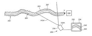
- FIG. 2 is an embodiment of an inventive system described herein for tracing a path of a ground-laid munitions command wire;
- FIG. 3A is a pictorial representation of an embodiment of an electrical exciter coupled to a command wire according to the inventive concepts, techniques, and systems;
- FIG. 3B is a pictorial representation of another embodiment of an electrical exciter coupled to a command wire according to the inventive concepts, techniques, and systems;
- FIG. 3C is a pictorial representation of a further embodiment of an electrical exciter coupled to a command wire according to the inventive concepts, techniques, and systems;
- FIG. 4 is a pictorial representation of an embodiment of an ultraviolet (UV) C-band imager of the type which may be used in the system of FIG. 2 ;
- UV ultraviolet
- FIG. 5 is a flow diagram of an embodiment of an inventive method described herein for tracing a ground-laid munitions command wire
- FIG. 6A is pictorial representation of an embodiment of positioning of a UV C-band detector for tracing portions of a path of a command wire;
- FIG. 6B is pictorial representation of another embodiment of positioning of a UV C-band detector for tracing portions of a path of a command wire;
- FIG. 6C is pictorial representation of an embodiment of the inventive concepts, systems, and techniques in which a UV C-band detector is positioned at a sufficient distance from the command wire to enable the entire path of the command wire to be traced in a single operation.
- ground-laid wire includes wire laid on and/or near the ground.
- ground-laid wire may include wire laid directly on the ground, such as on the Earth's surface, artificial ground such as roadways and other paved surfaces.
- Ground-laid wire may also include wire laid near the ground, such as over tree limbs, bushes, leaves, grass, and large exposed rocks. At least a portion of the ground-laid wire may pass through a cave. Furthermore, at least a portion of the ground-laid wire may be suspended off-the-ground, such as wire laid over a gap between two graded surfaces.
- a ground-laid wire 105 includes an initiation point 102 and a termination point 104 .
- the ground-laid wire 105 is a command wire for a munitions device 120 and the initiation point 102 is a detonation point 102 A from which the munitions device 120 is detonated, and the termination point 104 is an explosive production point 104 A at which the munitions device 120 is exploded 122 .
- a detonation mechanism 112 generates an electrical signal E that is carried over the ground-laid wire 105 from the detonation point 102 A to the explosive production point 104 A.
- the explosive production point 104 A provides the signal E as an output to munitions circuitry (not shown), which activates the munitions device 120 to produce the explosion 122 .
- the munitions device 120 can be any explosive device, such as a homemade bomb used in unconventional warfare, and may include conventional military components such as an artillery round. Terrorists, guerrillas, and/or commando forces may construct and deploy the munitions device 120 in military theaters or non-military settings.
- the munitions device 120 may be triggered using a mechanical mechanism 112 A, such as a handle or button that closes a circuit 112 B powered by an electrical storage device 112 C such as a battery, and provides the voltage signal E as an output to the command wire 105 .
- the munitions device 120 may be triggered using a remote control device 114 that communicates a signal to a receiver 116 to activate the detonation mechanism 112 and output signal E.
- the munitions device 120 may a road-side bomb triggered by a passing object (such as a vehicle) that produces a force on the munitions device 120 to activate the detonation circuit and initiate the explosion 122 .
- a passing object such as a vehicle
- Other triggering methods may be used such as trip wires.
- a system 200 includes an electrical exciter 210 adapted to apply a high-gradient voltage V to a ground-laid wire 205 capable of generating a corona 203 at an outer surface 207 of the ground-laid wire 205 .
- At least a portion of the corona includes ultraviolet (UV) C-band radiation.
- the system 200 includes an UV C-band detector 230 to detect the UV C-band radiation to enable tracing of a path 250 of the ground-laid wire 205 .
- the path of the wire 250 may be unknown; however, the system 200 may also be used to trace known or at least partially known command wire paths to, for example, verify a path of a command wire and/or to trace one or more missing portions of the path 250 . In other applications, the system 200 may be used to trace an unknown portion of a path of a command wire from a known point on the path before a munitions device is exploded to attempt to thwart the explosion, such as by deactivating and/or decommissioning the device.
- the electrical exciter 210 includes a device capable of providing a voltage over the wire 205 to generate the corona 203 .
- an electrical exciter may include an alternating current exciter, direct current exciter, a plasma exciter, an inverter, a radio-frequency exciter, or a taser®.
- the exciter 210 provides a voltage V in the range of about 1,000 volts to about 3,000 volts.
- a corona is an electro-static discharge, frequently luminous, at the surface of a conductor or between two conductors, accompanied by ionization of the surrounding atmosphere and often by a power loss. More particularly, as described herein, a corona 203 includes an electro-magnetic discharge generated at the outer surface of the wire 205 . At least a portion of the corona 203 includes UV C-band radiation in the range of about 200 nanometers (nm) to about 280 nm.
- UV C-band emission can occur when excited Nitrogen molecules (N 2 ) return to a ground state and emit a photon.
- N 2 molecules can be excited is by exposing them to high electrical voltage gradients. Both positive and negative gradients may produce excited N 2 molecules.
- the UV C-band radiation detector 230 includes a device capable of detecting light, including light in the UV C-band radiation range.
- a detector 230 may include a solid state device, such as a silicon carbide or aluminum nitride device, or a gas-filled tube.
- a detector 230 includes a UV C-band imager, a non-limiting example of which is the DayCor ⁇ Superb manufactured by Ofil Ltd. of Nes-Ziona, Israel, which is a sensitive bi-spectral visible light and UV C-band detection apparatus with absolute solar blind performance and with high pinpointing resolution.
- the detector 230 is a UV C-band camera 230 A that generates an image 232 on a display device 234 .
- the display device 234 may include a video monitor and/or an in-camera view-finder.
- the image 232 displays the UV C-band radiation detected within a field-of view (FOV) of the camera 230 A.
- FOV field-of view
- a detected corona 203 ′ will be produced along a visual path 250 ′ that generally corresponds of the path of the wire 250 .
- the image 232 displays a black background and a contrasting color, such as white, to represent the detected corona 203 ′.
- FIG. 2 shows the UV C-band detector 230 and electrical exciter 210 as separate components, in one or more embodiments a single structural unit can encompass the detector 230 and exciter 210 .
- the electrical exciter 210 may be coupled to the ground-laid wire 205 over a relatively long terminal to enable remote detection of the corona 203 .
- a ground-wire 305 as may be similar to ground-wire 205 described in conjunction with FIG. 2 , includes a first conductor 307 and a second conductor 309 , and an electrical exciter 310 , as may be similar to electrical exciter 210 described in conjunction with FIG. 2 .
- the electrical exciter 310 includes a first terminal 312 coupled to the first conductor 307 and a second terminal 314 coupled to the second conductor 309 .
- the first and second conductors 307 , 309 are twisted.
- a ground-wire 305 ′ as may be similar to ground-wire 205 described in conjunction with FIG. 2 , includes a first conductor 307 ′ and a second conductor 309 ′, and an electrical exciter 310 ′, as may be similar to electrical exciter 210 described in conjunction with FIG. 2 .
- the electrical exciter 310 ′ includes a first terminal 312 ′ coupled to the first conductor 307 ′.
- the electrical exciter 310 ′ is connected to ground 316 .
- a conductor such as a metal rod may be connected to the electrical exciter 310 ′ and inserted into the ground or soil.
- a ground-wire 305 ′′ as may be similar to ground-laid wire 205 described in conjunction with FIG. 2 , includes a first conductor 307 ′′ and a second conductor 309 ′′, and an electrical exciter 310 ′′, as may be similar to electrical exciter 210 described in conjunction with FIG. 2 .
- the electrical exciter 310 ′ includes a first terminal 312 ′′ coupled to the first conductor 307 ′′.
- the first terminal 312 ′′ is further coupled to the second conductor 309 ′′ via conductor 318 .
- ground-laid wire 205 may include a plurality of conductors, such as in a multi-conductor cable. Still further, the ground-laid wire 205 may include a stainless steel cable, metal-based fencing material, or any other material capable of carrying a current.
- the inventive concepts, techniques, and systems include an imager 430 capable of detecting UV C-band radiation 403 and visible light present within an environment 490 .
- the imager 430 generates an image 434 on a display device 432 that includes the detected UV C-band radiation 433 and the visual scene of the environment 423 .
- the detected UV C-band radiation 413 represents a corona generated by an exciter, as may be similar to exciter 210 described in conjunction with FIG. 2 , over a command wire for a munitions device.
- the imager 430 may include objective UV and/or zoom lenses, mirrors, and other components, generally denoted by reference numeral 455 .
- a detected UV C-band image 413 is transformed 415 to appear as a visual component 433 of the displayed image 434 which may overlap other displayed objects 436 within the environment 490 .
- a plurality of UV C-band detections is processed to calculate and render a line of best fit 437 representing an approximate path of the wire.
- a variety of methods may be used for computing a best fit and/or a trend-line from defined points including, but not limited to, a linear regression model using the least squares approach.
- the defined points represent detected UV C-band radiation and because very few objects emit such radiation, the resulting line of best fit 437 will correlate rather accurately with the path of the wire.
- a method 500 for tracing a ground-laid wire includes electrically exciting the wire to generate a corona at an outer surface of the wire 502 , the corona including UV C-band radiation, and tracing a path of the ground-laid wire using an UV C-band detector to detect the UV C-band radiation 506 .
- the method 500 includes positioning the UV C-band detector 504 to detect a first portion of the wire. If the first portion of the wire represents the entire path of the wire, then the method 500 may be terminated 508 . Otherwise, the method 500 further includes re-positioning the UV C-band detector 504 to trace a second portion of the wire.
- the method includes positioning the UV C-band detector 630 a number of times (i.e. two, three, or N times) to trace a number of portions (generally denoted by reference numeral 670 ) of a path of a wire 650 until a desired portion of a path of a wire 672 is traced.
- the desired portion of the path of the wire includes the entire path 650 of the ground-laid wire 605 from a starting point 650 A to an ending point 650 B.
- the traced portions may or may not overlap. Tracing overlapping portions may help ensure that portions of the path of the wire are not missed during tracing operations and, therefore, may help avoid tracing errors. However, it may be possible and may be quicker to trace non-overlapping portions of the path of the wire and to fill-in missing gaps by extrapolating between the non-overlapping portions.
- a first user 601 couples an electrical exciter 610 , as may be similar to electrical exciter 210 (and embodiments thereof) described in conjunction with FIG. 2 , to the first end 650 A of the ground-laid wire 605 to generate a corona 603 over the surface of the wire 605 , as may be similar to corona 203 described in conjunction with FIG. 2 .
- the first user 601 is a robotic device autonomously capable of performing the coupling task.
- the robotic device is remotely controlled by a human operator.
- the robotic device is provided coordinates for the first end 650 A of the ground-laid wire 605 .
- the first user 601 positions an UV C-band detector 630 at a first position 655 A to detect and trace a first portion 670 A of the ground-laid wire 605 .
- the first user 601 re-positions the detector 630 at a second position 655 B to detect a second portion 670 B of the ground-laid wire 605 .
- the first user 601 may further re-position 655 C the detector 630 until the first user 601 traces the entire path of the wire 650 from the starting point 650 A to the ending point 650 B, or a portion of the path of the wire.
- the first user 601 positions the detector 630 by rotating it about an axis R to trace one or more portions 670 ′ of the path of the wire 650 .
- the first user 601 traces a first portion 670 D of the path of the wire 650 by rotating the detector 630 a first angle ⁇ about axis R.
- First angle ⁇ is measured from a line L perpendicular to axis R (and in the plane of the paper) and generally parallel to the path of the wire 650 .
- the first user 601 traces respective second portion 670 E and third portion 670 F (and/or up to N portions) of the path of the wire 650 by rotating the detector 630 respective second angle ⁇ and third angle ⁇ .
- tracing the wire 605 includes tracing the entire path of the wire 650 in a single trace operation from a detection distance D.
- Distance D is any distance from which the entire path of the wire may be detected. Distance D will depend on various factors, such as the length of the wire, and obstacles that may impede the wire at certain positions from the wire. Other factors may affect the distance D such as the aperture of a camera detector and/or sensitivity of the detector and/or the intensity of the corona.
- a detector 630 may be mounted on an aircraft 675 to detect a corona 603 generated by an exciter 610 over the entire path of the ground-laid wire 650 .
- the aircraft 675 may include, but is not limited to, a drone aircraft, helicopter, fighter jet, balloon, etc.
- the first user 601 includes a plurality of users including an exciter user who sets up the exciter to generate the corona over the command wire and a detector user who operates the UV C-band detector to detect and trace the path of the wire 650 .
- a first user and a second user operate different UV C-band detectors to trace different portions of the path of the wire.
- the first and second users may perform the task simultaneously.
- the detected UV C-band radiation from each of the UV C-band detectors may be integrated to enable viewing as a single image.
- Such an arrangement may facilitate ground-laid munitions command wire tracing for relatively long command wires, such as 300 meters in length.
- simultaneous tracing by a plurality of UV C-band detectors may enable quicker tracing the path of the command wire to enable a quicker response to munitions detonation events.
Abstract
Description
Claims (22)
Priority Applications (1)
| Application Number | Priority Date | Filing Date | Title |
|---|---|---|---|
| US12/538,997 US8058875B2 (en) | 2009-08-11 | 2009-08-11 | Detection of ground-laid wire using ultraviolet C-band radiation |
Applications Claiming Priority (1)
| Application Number | Priority Date | Filing Date | Title |
|---|---|---|---|
| US12/538,997 US8058875B2 (en) | 2009-08-11 | 2009-08-11 | Detection of ground-laid wire using ultraviolet C-band radiation |
Publications (2)
| Publication Number | Publication Date |
|---|---|
| US20110037452A1 US20110037452A1 (en) | 2011-02-17 |
| US8058875B2 true US8058875B2 (en) | 2011-11-15 |
Family
ID=43588206
Family Applications (1)
| Application Number | Title | Priority Date | Filing Date |
|---|---|---|---|
| US12/538,997 Active 2030-06-23 US8058875B2 (en) | 2009-08-11 | 2009-08-11 | Detection of ground-laid wire using ultraviolet C-band radiation |
Country Status (1)
| Country | Link |
|---|---|
| US (1) | US8058875B2 (en) |
Citations (57)
| Publication number | Priority date | Publication date | Assignee | Title |
|---|---|---|---|---|
| US2944152A (en) | 1955-06-30 | 1960-07-05 | Mc Graw Edison Co | Fire detection |
| US3803463A (en) | 1972-07-10 | 1974-04-09 | J Cover | Weapon for immobilization and capture |
| US4253132A (en) | 1977-12-29 | 1981-02-24 | Cover John H | Power supply for weapon for immobilization and capture |
| US4376892A (en) | 1980-10-16 | 1983-03-15 | Agence Nationale De Valorisation De La Recherche (Anvar) | Detection and imaging of the spatial distribution of visible or ultraviolet photons |
| US4493114A (en) | 1983-05-02 | 1985-01-08 | The United States Of America As Represented By The Secretary Of The Navy | Optical non-line-of-sight covert, secure high data communication system |
| US4731881A (en) | 1986-06-30 | 1988-03-15 | The United States Of America As Represented By The Secretary Of The Navy | Narrow spectral bandwidth, UV solar blind detector |
| US5021668A (en) | 1989-01-16 | 1991-06-04 | Technion Research & Development Fdn. Ltd., Armament Development Authority | Electro-optical middle ultra-violet sensors |
| US5062154A (en) | 1989-03-03 | 1991-10-29 | The United States Of America As Represented By The Secretary Of The Navy | Mid range UV communications |
| US5191460A (en) | 1990-03-23 | 1993-03-02 | Gte Laboratories Incorporated | UV source for high data rate secure communication |
| US5301051A (en) | 1988-03-08 | 1994-04-05 | The United States Of America As Represented By The Secretary Of The Navy | Multi-channel, covert, non-line-of-sight UV communication |
| US5307194A (en) | 1992-03-24 | 1994-04-26 | Grumman Aerospace Corporation | Covert communication system using ultraviolet light |
| US5381098A (en) | 1993-01-04 | 1995-01-10 | Loftness; Marvin O. | Transmission line sparking locator |
| US5430604A (en) | 1993-09-17 | 1995-07-04 | Wong; Sam Q. | Hand-held electrostatic discharge generator |
| US5468963A (en) | 1987-05-19 | 1995-11-21 | British Aerospace Public Limited Company | Surveillance system |
| WO1996038831A1 (en) | 1995-05-30 | 1996-12-05 | Norris Electro Optical Systems Corporation | System for enhancing navigation and surveillance in low visibility conditions |
| US5839024A (en) * | 1997-05-19 | 1998-11-17 | Eastman Kodak Company | Corona charging of a charge retentive surface |
| WO2000023813A1 (en) | 1998-10-19 | 2000-04-27 | Sea Marshall Rescue Systems, Ltd. (Usa) | Improvements in and relating to emitters |
| US6104297A (en) | 1999-01-20 | 2000-08-15 | Danilychev; Vladimir A. | Corona discharge detection system |
| US20010029882A1 (en) | 1998-05-07 | 2001-10-18 | Dan Pharo | Personnel guidance and location control system |
| US20020104472A1 (en) | 2001-04-02 | 2002-08-08 | Neubert Timothy W. | Temporary airport safety ground transportation markers |
| US20030079671A1 (en) | 2001-10-31 | 2003-05-01 | Toyoda Gosei Co., Ltd. | Indication system of meter part |
| US20030150371A1 (en) | 2002-02-08 | 2003-08-14 | Snider Chris R. | Indicator knob with overmolded applique |
| US20040004826A1 (en) | 2001-05-14 | 2004-01-08 | Ryosuke Wakaki | Light emitting device and vehicle display device |
| US20040089219A1 (en) | 2000-12-22 | 2004-05-13 | Alf Burau | Indicating device with a pointer and a light source |
| US20040149199A1 (en) | 2003-01-15 | 2004-08-05 | Bae Systems Integrated Defense Solutions Inc. | Marking systems, methods and apparatuses |
| US20050078557A1 (en) | 2001-12-12 | 2005-04-14 | Alf Andersen | Sensor |
| US20050125926A1 (en) | 2003-07-24 | 2005-06-16 | Rekum Mireille V. | Cleaning article with indicator |
| US20050139142A1 (en) | 2002-02-06 | 2005-06-30 | Frank Kelley | Temperature indicator using thermochromic materials |
| US20050160963A1 (en) | 2002-02-12 | 2005-07-28 | Timo Siikaluoma | Device and method for detection/indication of liquid leakage |
| US20050217558A1 (en) | 2002-06-14 | 2005-10-06 | Fitzer Robert C | Shock indicator |
| US6954591B2 (en) | 1998-04-15 | 2005-10-11 | Lupton Elmer C | Non-visible communication systems |
| US20050253927A1 (en) | 2004-05-14 | 2005-11-17 | Allik Toomas H | Near infrared illuminated tripwire detector |
| US20050270175A1 (en) | 2003-09-18 | 2005-12-08 | Spot Devices, Inc. | Methods, systems and devices related to road mounted indicators for providing visual indications to approaching traffic |
| US20060065183A1 (en) | 2004-09-24 | 2006-03-30 | Drummond Scientific Company | Sealed-system critical temperature indicator |
| US20060164252A1 (en) | 2005-01-07 | 2006-07-27 | Richmond Simon N | Illuminated wind indicator |
| US20060169193A1 (en) | 2005-01-28 | 2006-08-03 | Korupt Kitens, L.L.C. | Ornament for a vehicle antenna |
| US20060174812A1 (en) | 2005-02-09 | 2006-08-10 | Christopher Marszalek | Apparatus, a system and a method for detecting a security of a device with an optical sensor |
| US20060260533A1 (en) | 2005-05-19 | 2006-11-23 | Thomas Parias | Expiration warning patch for gas expiration date management |
| US20060273087A1 (en) | 2005-06-02 | 2006-12-07 | Crawford Ross B | Lighted vessel for attachment to bottle |
| WO2007008738A1 (en) | 2005-07-07 | 2007-01-18 | See/Rescue Corporation | Water-activated and light-assisted visual locating device |
| US20070012237A1 (en) | 2005-07-16 | 2007-01-18 | Zdenek Nielsen | Pedestrian cross walk marker |
| US20070044704A1 (en) | 2005-08-30 | 2007-03-01 | Osborne Joseph H | Colored coating and formulation |
| US20070098407A1 (en) | 2002-07-19 | 2007-05-03 | Next Safety, Inc. | Methods and Apparatus for Communication Using UV Light |
| US20070119364A1 (en) | 2005-11-07 | 2007-05-31 | Taylor Dene H | Freeze indicators suitable for mass production |
| US20070125296A1 (en) | 2005-11-08 | 2007-06-07 | Taylor Dene H | Combination freeze indicators |
| US20070151502A1 (en) | 2001-08-10 | 2007-07-05 | Isadore Cooperman | Changed condition indicator |
| US20070221863A1 (en) | 2005-12-12 | 2007-09-27 | Zipf Edward C | Emission detector for the remote detection of explosives and illegal drugs |
| US20070253713A1 (en) | 2004-10-25 | 2007-11-01 | Bae Systems Information And Electronic Systems Integration Inc. | Solar Blind Ultraviolet Communication System for Unattended Ground Sensor Network |
| US20080000411A1 (en) | 2006-07-03 | 2008-01-03 | Tyler Easterwood | Protective barrier for a golf course flag stick |
| US20080022920A1 (en) | 2006-07-10 | 2008-01-31 | Patent-Treuhand-Gesellschaft Fur Elektrische Gluhlampen Mbh | Energy transducer module and light apparatus |
| US20080092800A1 (en) | 2006-10-20 | 2008-04-24 | Robert B. Smith | LED Light Bulb System |
| US20080110391A1 (en) | 2006-11-06 | 2008-05-15 | Taylor Dene H | Freeze indicators, flexible freeze indicators and manufacturing methods |
| US20080190354A1 (en) | 2006-10-30 | 2008-08-14 | Richard Edward Malpas | Detection system |
| US20080315116A1 (en) | 2006-12-21 | 2008-12-25 | Uv Doctor Management Llc | Optical UV lamp-on indicator |
| US20090010304A1 (en) | 2004-10-06 | 2009-01-08 | 3M Innovative Properties Company | Microstructured time dependent indicators |
| US20090145347A1 (en) | 2007-12-10 | 2009-06-11 | Konica Minolta Business Technologies, Inc. | Indication member |
| US20090178608A1 (en) | 2007-12-12 | 2009-07-16 | Shaw Mark D | Tactile warning pad with shearable anchor members |
-
2009
- 2009-08-11 US US12/538,997 patent/US8058875B2/en active Active
Patent Citations (58)
| Publication number | Priority date | Publication date | Assignee | Title |
|---|---|---|---|---|
| US2944152A (en) | 1955-06-30 | 1960-07-05 | Mc Graw Edison Co | Fire detection |
| US3803463A (en) | 1972-07-10 | 1974-04-09 | J Cover | Weapon for immobilization and capture |
| US4253132A (en) | 1977-12-29 | 1981-02-24 | Cover John H | Power supply for weapon for immobilization and capture |
| US4376892A (en) | 1980-10-16 | 1983-03-15 | Agence Nationale De Valorisation De La Recherche (Anvar) | Detection and imaging of the spatial distribution of visible or ultraviolet photons |
| US4493114A (en) | 1983-05-02 | 1985-01-08 | The United States Of America As Represented By The Secretary Of The Navy | Optical non-line-of-sight covert, secure high data communication system |
| US4731881A (en) | 1986-06-30 | 1988-03-15 | The United States Of America As Represented By The Secretary Of The Navy | Narrow spectral bandwidth, UV solar blind detector |
| US5468963A (en) | 1987-05-19 | 1995-11-21 | British Aerospace Public Limited Company | Surveillance system |
| US5301051A (en) | 1988-03-08 | 1994-04-05 | The United States Of America As Represented By The Secretary Of The Navy | Multi-channel, covert, non-line-of-sight UV communication |
| US5021668A (en) | 1989-01-16 | 1991-06-04 | Technion Research & Development Fdn. Ltd., Armament Development Authority | Electro-optical middle ultra-violet sensors |
| US5062154A (en) | 1989-03-03 | 1991-10-29 | The United States Of America As Represented By The Secretary Of The Navy | Mid range UV communications |
| US5191460A (en) | 1990-03-23 | 1993-03-02 | Gte Laboratories Incorporated | UV source for high data rate secure communication |
| US5307194A (en) | 1992-03-24 | 1994-04-26 | Grumman Aerospace Corporation | Covert communication system using ultraviolet light |
| US5381098A (en) | 1993-01-04 | 1995-01-10 | Loftness; Marvin O. | Transmission line sparking locator |
| US5430604A (en) | 1993-09-17 | 1995-07-04 | Wong; Sam Q. | Hand-held electrostatic discharge generator |
| WO1996038831A1 (en) | 1995-05-30 | 1996-12-05 | Norris Electro Optical Systems Corporation | System for enhancing navigation and surveillance in low visibility conditions |
| US5719567A (en) | 1995-05-30 | 1998-02-17 | Victor J. Norris, Jr. | System for enhancing navigation and surveillance in low visibility conditions |
| US5839024A (en) * | 1997-05-19 | 1998-11-17 | Eastman Kodak Company | Corona charging of a charge retentive surface |
| US6954591B2 (en) | 1998-04-15 | 2005-10-11 | Lupton Elmer C | Non-visible communication systems |
| US20010029882A1 (en) | 1998-05-07 | 2001-10-18 | Dan Pharo | Personnel guidance and location control system |
| WO2000023813A1 (en) | 1998-10-19 | 2000-04-27 | Sea Marshall Rescue Systems, Ltd. (Usa) | Improvements in and relating to emitters |
| US6104297A (en) | 1999-01-20 | 2000-08-15 | Danilychev; Vladimir A. | Corona discharge detection system |
| US20040089219A1 (en) | 2000-12-22 | 2004-05-13 | Alf Burau | Indicating device with a pointer and a light source |
| US20020104472A1 (en) | 2001-04-02 | 2002-08-08 | Neubert Timothy W. | Temporary airport safety ground transportation markers |
| US20040004826A1 (en) | 2001-05-14 | 2004-01-08 | Ryosuke Wakaki | Light emitting device and vehicle display device |
| US20070151502A1 (en) | 2001-08-10 | 2007-07-05 | Isadore Cooperman | Changed condition indicator |
| US20030079671A1 (en) | 2001-10-31 | 2003-05-01 | Toyoda Gosei Co., Ltd. | Indication system of meter part |
| US20050078557A1 (en) | 2001-12-12 | 2005-04-14 | Alf Andersen | Sensor |
| US20050139142A1 (en) | 2002-02-06 | 2005-06-30 | Frank Kelley | Temperature indicator using thermochromic materials |
| US20030150371A1 (en) | 2002-02-08 | 2003-08-14 | Snider Chris R. | Indicator knob with overmolded applique |
| US20050160963A1 (en) | 2002-02-12 | 2005-07-28 | Timo Siikaluoma | Device and method for detection/indication of liquid leakage |
| US20050217558A1 (en) | 2002-06-14 | 2005-10-06 | Fitzer Robert C | Shock indicator |
| US20070098407A1 (en) | 2002-07-19 | 2007-05-03 | Next Safety, Inc. | Methods and Apparatus for Communication Using UV Light |
| US20040149199A1 (en) | 2003-01-15 | 2004-08-05 | Bae Systems Integrated Defense Solutions Inc. | Marking systems, methods and apparatuses |
| US20050125926A1 (en) | 2003-07-24 | 2005-06-16 | Rekum Mireille V. | Cleaning article with indicator |
| US20050270175A1 (en) | 2003-09-18 | 2005-12-08 | Spot Devices, Inc. | Methods, systems and devices related to road mounted indicators for providing visual indications to approaching traffic |
| US20050253927A1 (en) | 2004-05-14 | 2005-11-17 | Allik Toomas H | Near infrared illuminated tripwire detector |
| US20060065183A1 (en) | 2004-09-24 | 2006-03-30 | Drummond Scientific Company | Sealed-system critical temperature indicator |
| US20090010304A1 (en) | 2004-10-06 | 2009-01-08 | 3M Innovative Properties Company | Microstructured time dependent indicators |
| US20070253713A1 (en) | 2004-10-25 | 2007-11-01 | Bae Systems Information And Electronic Systems Integration Inc. | Solar Blind Ultraviolet Communication System for Unattended Ground Sensor Network |
| US20060164252A1 (en) | 2005-01-07 | 2006-07-27 | Richmond Simon N | Illuminated wind indicator |
| US20060169193A1 (en) | 2005-01-28 | 2006-08-03 | Korupt Kitens, L.L.C. | Ornament for a vehicle antenna |
| US20060174812A1 (en) | 2005-02-09 | 2006-08-10 | Christopher Marszalek | Apparatus, a system and a method for detecting a security of a device with an optical sensor |
| US20060260533A1 (en) | 2005-05-19 | 2006-11-23 | Thomas Parias | Expiration warning patch for gas expiration date management |
| US20060273087A1 (en) | 2005-06-02 | 2006-12-07 | Crawford Ross B | Lighted vessel for attachment to bottle |
| WO2007008738A1 (en) | 2005-07-07 | 2007-01-18 | See/Rescue Corporation | Water-activated and light-assisted visual locating device |
| US20070012237A1 (en) | 2005-07-16 | 2007-01-18 | Zdenek Nielsen | Pedestrian cross walk marker |
| US20070044704A1 (en) | 2005-08-30 | 2007-03-01 | Osborne Joseph H | Colored coating and formulation |
| US20070119364A1 (en) | 2005-11-07 | 2007-05-31 | Taylor Dene H | Freeze indicators suitable for mass production |
| US20070125296A1 (en) | 2005-11-08 | 2007-06-07 | Taylor Dene H | Combination freeze indicators |
| US20070221863A1 (en) | 2005-12-12 | 2007-09-27 | Zipf Edward C | Emission detector for the remote detection of explosives and illegal drugs |
| US20080000411A1 (en) | 2006-07-03 | 2008-01-03 | Tyler Easterwood | Protective barrier for a golf course flag stick |
| US20080022920A1 (en) | 2006-07-10 | 2008-01-31 | Patent-Treuhand-Gesellschaft Fur Elektrische Gluhlampen Mbh | Energy transducer module and light apparatus |
| US20080092800A1 (en) | 2006-10-20 | 2008-04-24 | Robert B. Smith | LED Light Bulb System |
| US20080190354A1 (en) | 2006-10-30 | 2008-08-14 | Richard Edward Malpas | Detection system |
| US20080110391A1 (en) | 2006-11-06 | 2008-05-15 | Taylor Dene H | Freeze indicators, flexible freeze indicators and manufacturing methods |
| US20080315116A1 (en) | 2006-12-21 | 2008-12-25 | Uv Doctor Management Llc | Optical UV lamp-on indicator |
| US20090145347A1 (en) | 2007-12-10 | 2009-06-11 | Konica Minolta Business Technologies, Inc. | Indication member |
| US20090178608A1 (en) | 2007-12-12 | 2009-07-16 | Shaw Mark D | Tactile warning pad with shearable anchor members |
Non-Patent Citations (11)
| Title |
|---|
| "DayCor ® Superb Corona Detection Systems Based on UV Solar Blind Technology" http://www.daycor.com/DayCor-Family/P-superb.html, 2 pages, last visited Aug 10, 2009. |
| "Installation & Operation Manual SSD110/113 Series" Plasma Technics Inc., Version: Rev 2.2, 2006, 32 pages, http://www.plasmatechnics.com. |
| "SSD110-Solid State Drive", Plasma Technics Inc.®, 70159-cutsheet, 2 pages, http://www.plasmatechnics.com. |
| "Transforming Law Enforcement Safety X26(TM) Taser ®" Taser International, Inc., MBR0005 Rev: A, 2009, 2 pages, http://www.taser.com/SiteCollectionDocuments/Downloads/x26-trifold.pdf, 2 pages, last visited Aug 12, 2009. |
| "Transforming Law Enforcement Safety X26™ Taser ®" Taser International, Inc., MBR0005 Rev: A, 2009, 2 pages, http://www.taser.com/SiteCollectionDocuments/Downloads/x26—trifold.pdf, 2 pages, last visited Aug 12, 2009. |
| Hamamatsu, Flame Sensor UV Tron ® 2868. "Quick Detection of Flame from Distance, Compact UV Sensor with High Sensitivity and Wide Directivity, Suitable for Flame Detectors and Fire Alarms", 1997 Hamamatsu Photonics K.K., pp. 1-2, http://www.acroname.com/robotics/parts/R66-R2868.pdf, last visited Aug 10, 2009. |
| International Search Report, Form PCT/ISA/210, PCT/US2010/046285, date of mailing Nov. 12, 2010, 3 pages. |
| Notification of Transmittal of the International Search Report and the Written Opinion of the ISA, or the Declaration, PCT/US2010/046285, date of mailing Nov. 12, 2010, 1 page. |
| U.S. Appl. No. 12/538,997, filed Sep. 4, 2009. |
| Utility U.S. Appl. No. 12/902,438, filed Oct. 12, 2010, 39 pages. |
| Written Opinion of the International Searching Authority, PCT/US2010/046285 date of mailing Nov. 12, 2010, 5 pages. |
Also Published As
| Publication number | Publication date |
|---|---|
| US20110037452A1 (en) | 2011-02-17 |
Similar Documents
| Publication | Publication Date | Title |
|---|---|---|
| JP5913453B2 (en) | Search and rescue using ultraviolet radiation | |
| US8441360B2 (en) | Search and rescue using ultraviolet radiation | |
| ES2380322T3 (en) | UV light insensitive device and camera | |
| WO2021207557A1 (en) | Multispectral imaging for thermal and electrical detection systems and methods | |
| CN101706548A (en) | Optical detection device for corona discharge | |
| Sadovnichy et al. | Prompt and Follow-up Multi-wavelength Observations of the GRB 161017A | |
| US8058875B2 (en) | Detection of ground-laid wire using ultraviolet C-band radiation | |
| Vestrand et al. | RAPTOR: Closed‐Loop monitoring of the night sky and the earliest optical detection of GRB 021211 | |
| EP2500749B1 (en) | Integrated system for fighting against improvised explosive devices | |
| Dulk et al. | Search for visual aurorae on Jupiter | |
| Maini | Optoelectronics for Low-Intensity Conflicts and Homeland Security | |
| US11774353B2 (en) | Methods and apparatuses for biomimetic standoff detection of hazardous chemicals | |
| Nuthan et al. | Camouflage Technique Based Multifunctional Army Robot | |
| Roos et al. | ENERGY CONTROL IN ELECTRO-SPRAY, ELECTRO-DISTILLATION AND ELECTRIC WIND APPLICATIONS, AN INNOVATION RESUME. | |
| Yan et al. | Analysis of applying SBUVICCD to corona detection | |
| Fulton et al. | Night vision electro-optics technology transfer: a decade of activity | |
| Hagen et al. | Conference 8710: Chemical, Biological, Radiological, Nuclear, and Explosives (CBRNE) Sensing XIV | |
| FR2869682A1 (en) | Weapon for remotely destructing electric materials, electronic circuits and configuration of e.g. computer, has anticathode to create hard X ray beams passing through cathode and directed to focal point of system to be destructed | |
| Cremers et al. | Development and testing of a prototype LIBS instrument for a NASA Mars rover | |
| Martin et al. | Using Optical Nitrogen Fluorescence to Detect and Characterize Ionizing Radiation in the Atmosphere. | |
| Zhang et al. | Human-technology interaction for standoff IED detection | |
| Medvedev et al. | Specific Features of Solar Blind UV-Range Devices | |
| Talley | Remotely triggered solar blind signaling using deep ultraviolet (UV) LEDs | |
| Vestrand et al. | Mining the Sky for Explosive Optical Transients with Both Eyes Open | |
| Gupta et al. | Optical flux and spectral variability of blazars |
Legal Events
| Date | Code | Title | Description |
|---|---|---|---|
| AS | Assignment |
Owner name: RAYTHEON COMPANY, MASSACHUSETTS Free format text: ASSIGNMENT OF ASSIGNORS INTEREST;ASSIGNOR:WITZEL, JOHN GEORGE;REEL/FRAME:023089/0465 Effective date: 20090807 |
|
| AS | Assignment |
Owner name: RAYTHEON UTD, INC., VIRGINIA Free format text: ASSIGNMENT OF ASSIGNORS INTEREST;ASSIGNOR:RAYTHEON COMPANY;REEL/FRAME:024080/0794 Effective date: 20100224 |
|
| FEPP | Fee payment procedure |
Free format text: PAYOR NUMBER ASSIGNED (ORIGINAL EVENT CODE: ASPN); ENTITY STATUS OF PATENT OWNER: LARGE ENTITY |
|
| STCF | Information on status: patent grant |
Free format text: PATENTED CASE |
|
| AS | Assignment |
Owner name: RAYTHEON COMPANY, MASSACHUSETTS Free format text: MERGER;ASSIGNOR:RAYTHEON UTD INC.;REEL/FRAME:027515/0784 Effective date: 20111216 |
|
| FPAY | Fee payment |
Year of fee payment: 4 |
|
| MAFP | Maintenance fee payment |
Free format text: PAYMENT OF MAINTENANCE FEE, 8TH YEAR, LARGE ENTITY (ORIGINAL EVENT CODE: M1552); ENTITY STATUS OF PATENT OWNER: LARGE ENTITY Year of fee payment: 8 |
|
| MAFP | Maintenance fee payment |
Free format text: PAYMENT OF MAINTENANCE FEE, 12TH YEAR, LARGE ENTITY (ORIGINAL EVENT CODE: M1553); ENTITY STATUS OF PATENT OWNER: LARGE ENTITY Year of fee payment: 12 |