US8752575B2 - Faucet including cartridge assembly with radially offset key - Google Patents
Faucet including cartridge assembly with radially offset key Download PDFInfo
- Publication number
- US8752575B2 US8752575B2 US13/551,188 US201213551188A US8752575B2 US 8752575 B2 US8752575 B2 US 8752575B2 US 201213551188 A US201213551188 A US 201213551188A US 8752575 B2 US8752575 B2 US 8752575B2
- Authority
- US
- United States
- Prior art keywords
- keys
- pair
- key
- cartridge shell
- faucet
- Prior art date
- Legal status (The legal status is an assumption and is not a legal conclusion. Google has not performed a legal analysis and makes no representation as to the accuracy of the status listed.)
- Active, expires
Links
Images


Classifications
-
- F—MECHANICAL ENGINEERING; LIGHTING; HEATING; WEAPONS; BLASTING
- F16—ENGINEERING ELEMENTS AND UNITS; GENERAL MEASURES FOR PRODUCING AND MAINTAINING EFFECTIVE FUNCTIONING OF MACHINES OR INSTALLATIONS; THERMAL INSULATION IN GENERAL
- F16K—VALVES; TAPS; COCKS; ACTUATING-FLOATS; DEVICES FOR VENTING OR AERATING
- F16K3/00—Gate valves or sliding valves, i.e. cut-off apparatus with closing members having a sliding movement along the seat for opening and closing
- F16K3/02—Gate valves or sliding valves, i.e. cut-off apparatus with closing members having a sliding movement along the seat for opening and closing with flat sealing faces; Packings therefor
- F16K3/04—Gate valves or sliding valves, i.e. cut-off apparatus with closing members having a sliding movement along the seat for opening and closing with flat sealing faces; Packings therefor with pivoted closure members
-
- F—MECHANICAL ENGINEERING; LIGHTING; HEATING; WEAPONS; BLASTING
- F16—ENGINEERING ELEMENTS AND UNITS; GENERAL MEASURES FOR PRODUCING AND MAINTAINING EFFECTIVE FUNCTIONING OF MACHINES OR INSTALLATIONS; THERMAL INSULATION IN GENERAL
- F16K—VALVES; TAPS; COCKS; ACTUATING-FLOATS; DEVICES FOR VENTING OR AERATING
- F16K27/00—Construction of housing; Use of materials therefor
- F16K27/04—Construction of housing; Use of materials therefor of sliding valves
- F16K27/044—Construction of housing; Use of materials therefor of sliding valves slide valves with flat obturating members
- F16K27/045—Construction of housing; Use of materials therefor of sliding valves slide valves with flat obturating members with pivotal obturating members
-
- Y—GENERAL TAGGING OF NEW TECHNOLOGICAL DEVELOPMENTS; GENERAL TAGGING OF CROSS-SECTIONAL TECHNOLOGIES SPANNING OVER SEVERAL SECTIONS OF THE IPC; TECHNICAL SUBJECTS COVERED BY FORMER USPC CROSS-REFERENCE ART COLLECTIONS [XRACs] AND DIGESTS
- Y10—TECHNICAL SUBJECTS COVERED BY FORMER USPC
- Y10T—TECHNICAL SUBJECTS COVERED BY FORMER US CLASSIFICATION
- Y10T137/00—Fluid handling
- Y10T137/7504—Removable valve head and seat unit
- Y10T137/7668—Retained by bonnet or closure
-
- Y—GENERAL TAGGING OF NEW TECHNOLOGICAL DEVELOPMENTS; GENERAL TAGGING OF CROSS-SECTIONAL TECHNOLOGIES SPANNING OVER SEVERAL SECTIONS OF THE IPC; TECHNICAL SUBJECTS COVERED BY FORMER USPC CROSS-REFERENCE ART COLLECTIONS [XRACs] AND DIGESTS
- Y10—TECHNICAL SUBJECTS COVERED BY FORMER USPC
- Y10T—TECHNICAL SUBJECTS COVERED BY FORMER US CLASSIFICATION
- Y10T137/00—Fluid handling
- Y10T137/8593—Systems
- Y10T137/86493—Multi-way valve unit
- Y10T137/86815—Multiple inlet with single outlet
-
- Y—GENERAL TAGGING OF NEW TECHNOLOGICAL DEVELOPMENTS; GENERAL TAGGING OF CROSS-SECTIONAL TECHNOLOGIES SPANNING OVER SEVERAL SECTIONS OF THE IPC; TECHNICAL SUBJECTS COVERED BY FORMER USPC CROSS-REFERENCE ART COLLECTIONS [XRACs] AND DIGESTS
- Y10—TECHNICAL SUBJECTS COVERED BY FORMER USPC
- Y10T—TECHNICAL SUBJECTS COVERED BY FORMER US CLASSIFICATION
- Y10T137/00—Fluid handling
- Y10T137/9464—Faucets and spouts
Definitions
- the present invention relates generally to a faucet including a cartridge assembly, and, more particularly, to a faucet including a cartridge assembly with a radially offset key.
- cartridge assemblies are installed in valve bodies. Rotation of a cartridge assembly within a valve body can damage the faucet and even render the faucet inoperable.
- the cartridge assembly can include a key and the valve body can include a corresponding keyway.
- Prior keys and keyways include a center line that intersects a central longitudinal axis of the cartridge assembly.
- the present invention provides a faucet including a cartridge assembly with a radially offset key.
- the faucet includes a cartridge shell.
- the cartridge shell includes a first end and a second end.
- the cartridge shell has an exterior surface.
- the cartridge shell has an interior with a central longitudinal axis extending through a center of the interior from the first end to the second end.
- the faucet includes a key extending from the exterior surface of the cartridge shell.
- the key has an inner side and an outer side.
- the inner side and the outer side of the key lie in a plane through the first end of the cartridge shell that is perpendicular to the central longitudinal axis of the cartridge shell.
- the key has a center line extending through a center of the inner side of the key and through a center of the outer side of the key.
- the center line of the key does not intersect the central longitudinal axis of the cartridge shell.
- the faucet in another exemplary embodiment, includes a cartridge shell.
- the cartridge shell includes a first end and a second end.
- the cartridge shell has an exterior surface.
- the cartridge shell has an interior with a central longitudinal axis extending through a center of the interior from the first end to the second end.
- the faucet includes a pair of keys extending from the exterior surface of the cartridge shell.
- Each key has an inner side and an outer side. The inner side and the outer side of each key lie in a plane through the first end of the cartridge shell that is perpendicular to the central longitudinal axis of the cartridge shell.
- Each key has a center line extending through a center of the inner side of the key and through a center of the outer side of each key. The center line of each key does not intersect the central longitudinal axis of the cartridge shell.
- the faucet in another exemplary embodiment, includes a cartridge shell.
- the cartridge shell includes a first end and a second end.
- the cartridge shell has an exterior surface.
- the cartridge shell has an interior with a central longitudinal axis extending through a center of the interior from the first end to the second end.
- the faucet includes a first pair of keys extending from the exterior surface of the cartridge shell.
- the first pair keys are diametrically opposed to each other.
- Each of the first pair of keys has an inner side and an outer side. The inner side and the outer side of each first pair key lie in a plane through the first end of the cartridge shell that is perpendicular to the central longitudinal axis of the cartridge shell.
- Each first pair key has a center line extending through a center of the inner side of the key and through a center of the outer side of key.
- the center line of one of the first pair of keys is common with the center line of another of the first pair of keys.
- the faucet includes a second pair of keys extending from the exterior surface of the cartridge shell.
- the second pair keys are diametrically opposed to each other.
- Each of the second pair of keys has an inner side and an outer side.
- the inner side and the outer side of each second pair key lie in a plane through the first end of the cartridge shell that is perpendicular to the central longitudinal axis of the cartridge shell.
- Each second pair key has a center line extending through a center of the inner side of the key and through a center of the outer side of key.
- the center line of one of the second pair of keys is common with the center line of another of the second pair of keys.
- the first pair keys are diametrically opposed to the second pair keys.
- the center line of the first pair of keys is parallel to the center line of the second pair of keys.
- the center line of the first pair of keys does not intersect the central longitudinal axis of the cartridge shell.
- the center line of the second pair of keys does not intersect the central longitudinal axis of the cartridge shell.
- FIG. 1 is a perspective view of a cartridge assembly installed in a valve body according to an exemplary embodiment of the present invention
- FIG. 2 is an exploded perspective view of the cartridge assembly of FIG. 1 ;
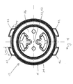
- FIG. 3 is a top plan view of the cartridge assembly of FIG. 2 ;
- FIG. 4 is a bottom plan view of the cartridge assembly of FIG. 2 ;
- FIG. 5 is a cross-sectional view of the cartridge assembly of FIG. 2 along the line A-A in FIG. 3 ;
- FIG. 6 is a cross-sectional view of the cartridge assembly of FIG. 2 along the line B-B in FIG. 3 .
- the present invention provides a faucet including a cartridge assembly with a radially offset key.
- An exemplary embodiment of a cartridge assembly 10 of the present invention is shown in FIGS. 1-6 .
- the cartridge assembly 10 is installed in a valve body 12 .
- the cartridge assembly 10 includes a cartridge shell 14 , a stem seal 16 , a stem 18 , a moveable disk 20 , a fixed disk 22 , a base seal 24 , a base seal support 26 , and a shell seal 28 .
- Cartridge assemblies and valve bodies are well-known in the art and, therefore, only the relevant components of the cartridge assembly 10 and the valve body 12 will be described in greater detail.
- the cartridge shell 14 includes a first end 30 and a second end 32 .
- the cartridge shell 14 has an exterior surface 34 with a generally cylindrical shape.
- the cartridge shell 14 has an interior 36 with a central longitudinal axis 38 extending through a center 40 of the interior 36 from the first end 30 to the second end 32 .
- the cartridge shell 14 can be formed of plastic, metal, or any other suitable material.
- each key 42 extends from the exterior surface 34 of the cartridge shell 14 .
- Each key 42 can be integrally formed with the cartridge shell 14 or can be securely affixed to the cartridge shell 14 .
- Each key 42 is generally parallelepiped shaped.
- each key 42 has an inner side 44 and an outer side 46 .
- the inner side 44 of each key 42 is formed by an interface between the key 42 and the cartridge shell 14 .
- a dashed line has been added in FIG. 3 to illustrate the inner side 44 of each key 42 .
- each key has a first side 48 and a second side 50 .
- the inner side 44 , the outer side 46 , the first side 48 , and the second side 50 of each key 42 lie in a plane through the first end 30 of the cartridge shell 14 that is perpendicular to the central longitudinal axis 38 of the cartridge shell 14 .
- the inner side 44 of each key 42 is generally parallel to the outer side 46 of each key 42 .
- each key 42 has a center line 52 extending through a center 54 of the inner side 44 of the key 42 and through a center 56 of the outer side 46 of the key 42 .
- the center line 52 of each key 42 does not intersect the central longitudinal axis 38 of the cartridge shell 14 . As a result, each key 42 is considered radially offset.
- a length (l key ) of each key 42 is approximately one-eighteenth of a circumference of the exterior surface 34 of the cartridge shell 14 .
- a depth (d key ) of each key 42 is approximately one-fourteenth of a diameter of the exterior surface 34 of the cartridge shell 14 .
- a height (h key ) of each key 42 is approximately one-fifth of a height (h shell ) of the exterior surface 34 of the cartridge shell 14 .
- the valve body 12 includes a first end 58 and a second end 60 .
- the valve body 12 has an exterior surface 62 with a generally cylindrical shape.
- the valve body 12 has an interior surface 64 with a generally cylindrical shape.
- the interior surface 64 of the valve body 12 generally corresponds to the exterior surface 34 of the cartridge shell 14 .
- the valve body 12 can be a one-handle valve body or a two-handle valve body.
- the valve body 12 can be formed of plastic, metal, or any other suitable material.
- the valve body 12 includes four (4) keyways 66 for receiving the four (4) keys 42 .
- the shape of each keyway 66 generally corresponds to the shape of each key 42 .
- Each keyway 66 can be formed as a groove in the interior surface 64 of the valve body 12 or can be formed as a notch through the interior surface 64 and through the exterior surface 62 of the valve body 12 .
- Each keyway 66 can be formed by broaching, machining, or any other suitable method.
- the cartridge assembly 10 is inserted into the valve body 12 . More specifically, the second end 32 of the cartridge shell 14 is inserted into the first end 58 of the valve body 12 . The cartridge assembly 10 is further inserted into the valve body 12 until the first end 30 of the cartridge shell 14 is generally aligned with the first end 58 of the valve body 12 .
- the interaction of the keys 42 with the keyways 66 resists rotation of the cartridge shell 14 , and thus the cartridge assembly 10 , within the valve body 12 .
- the keys 42 can generally withstand at least one-hundred twenty (120) inch pounds of force.
- cartridge assembly 10 has been described as including four (4) keys 42 and the valve body 12 has been described as including four (4) keyways 66 , one of ordinary skill in the art will appreciate that the cartridge assembly 10 could include more or less than four (4) keys 42 and the valve body 12 could include more or less than four (4) keyways 66 .
- the number of keyways 66 corresponds to the number of keys 42 .
- the cartridge assembly 10 includes a single key 42 and the valve body 12 includes a single keyway 66 .
- the center line 52 does not intersect the central longitudinal axis 38 of the cartridge shell 14 .
- the cartridge assembly 10 includes a pair of keys 42 and the valve body 12 includes a pair of keyways 66 .
- the keys 42 are diametrically opposed to each other, and the keyways 66 are diametrically opposed to each other.
- the center line 52 of one of the pair of keys 42 is common with the center line 52 of another of the pair of keys 42 .
- the center line 52 of the pair of keys 42 does not intersect the central longitudinal axis 38 of the cartridge shell 14 .
- the cartridge assembly 10 includes a pair of keys 42 and the valve body 12 includes a pair of keyways 66 .
- the keys 42 are diametrically offset from each other, and the keyways 66 are diametrically offset from each other.
- the center line 52 of one of the pair of keys 42 is parallel to the center line 52 of another of the pair of keys 42 .
- the center lines 52 of the pair of keys 42 do not intersect the central longitudinal axis 38 of the cartridge shell 14 .
- the cartridge assembly 10 includes two pairs of keys 42 and the valve body 12 includes two pairs of keyways 66 .
- the first pair keys 42 are diametrically opposed to each other, and the first pair keyways 66 are diametrically opposed to each other.
- the second pair keys 42 are diametrically opposed to each other, and the second pair keyways 66 are diametrically opposed to each other.
- the first pair keys 42 are diametrically offset from the second pair keys 42
- the first pair keyways 66 are diametrically offset from the second pair keyways 66 .
- the center line 52 of one of the first pair of keys 42 is common with the center line 52 of another of the first pair of keys 42
- the center line 52 of one of the second pair of keys 42 is common with the center line 52 of another of the second pair of keys 42
- the center line 52 of the first pair of keys 42 is parallel to the center line 52 of the second pair of keys 42 .
- the center line 52 of the first pair of keys 42 does not intersect the central longitudinal axis 38 of the cartridge shell 14
- the center line 52 of the second pair of keys 42 does not intersect the central longitudinal axis 38 of the cartridge shell 14 .
- the interaction of the keys 42 with the keyways 66 resists rotation of the cartridge shell 14 , and thus the cartridge assembly 10 , within the valve body 12 .
Abstract
Description
Claims (20)
Priority Applications (2)
| Application Number | Priority Date | Filing Date | Title |
|---|---|---|---|
| US13/551,188 US8752575B2 (en) | 2012-07-17 | 2012-07-17 | Faucet including cartridge assembly with radially offset key |
| PCT/US2013/050486 WO2014014820A2 (en) | 2012-07-17 | 2013-07-15 | Faucet including cartridge assembly with radially offset key |
Applications Claiming Priority (1)
| Application Number | Priority Date | Filing Date | Title |
|---|---|---|---|
| US13/551,188 US8752575B2 (en) | 2012-07-17 | 2012-07-17 | Faucet including cartridge assembly with radially offset key |
Publications (2)
| Publication Number | Publication Date |
|---|---|
| US20140020777A1 US20140020777A1 (en) | 2014-01-23 |
| US8752575B2 true US8752575B2 (en) | 2014-06-17 |
Family
ID=49945536
Family Applications (1)
| Application Number | Title | Priority Date | Filing Date |
|---|---|---|---|
| US13/551,188 Active 2032-12-07 US8752575B2 (en) | 2012-07-17 | 2012-07-17 | Faucet including cartridge assembly with radially offset key |
Country Status (2)
| Country | Link |
|---|---|
| US (1) | US8752575B2 (en) |
| WO (1) | WO2014014820A2 (en) |
Cited By (2)
| Publication number | Priority date | Publication date | Assignee | Title |
|---|---|---|---|---|
| USD736897S1 (en) | 2014-03-17 | 2015-08-18 | Moen Incorporated | Faucet cartridge |
| US20170350516A1 (en) * | 2016-06-02 | 2017-12-07 | Wen Wang | Valve for a Faucet Assembly |
Families Citing this family (6)
| Publication number | Priority date | Publication date | Assignee | Title |
|---|---|---|---|---|
| USD745638S1 (en) * | 2014-02-28 | 2015-12-15 | Rock Smasher Engineering | Tank valve |
| USD779046S1 (en) * | 2015-09-21 | 2017-02-14 | Fountain Master, Llc | Threaded connector |
| US10981189B2 (en) | 2017-07-07 | 2021-04-20 | Anvil International, Llc | Hanging connector for flexible sprinkler conduit |
| USD910420S1 (en) * | 2017-08-25 | 2021-02-16 | Gem Products, Inc. | Attachment point for an outrigger guide |
| USD854915S1 (en) * | 2017-11-08 | 2019-07-30 | Anvil International, Llc | Conduit hanger adapter |
| US20200149253A1 (en) * | 2018-11-13 | 2020-05-14 | Greatness Sanitary Industrial Co., Ltd | Rotary control structure for water valve |
Citations (39)
| Publication number | Priority date | Publication date | Assignee | Title |
|---|---|---|---|---|
| US3548875A (en) | 1969-03-28 | 1970-12-22 | Speakman Co | Valve cartridge |
| US3680592A (en) | 1970-05-01 | 1972-08-01 | Hydrometals Inc | Single handle faucet valve |
| US3698418A (en) | 1971-07-01 | 1972-10-17 | Milwaukee Faucets | Non-rise valve for faucets or the like |
| US3788356A (en) | 1972-08-03 | 1974-01-29 | A Moen | Faucet construction |
| US3799191A (en) | 1972-01-31 | 1974-03-26 | Exxon Production Research Co | Compartmented underwater equipment |
| US4109672A (en) | 1977-07-29 | 1978-08-29 | Price-Pfister Brass Mfg. Co. | Snap-in valve cartridge |
| US4226260A (en) | 1979-08-29 | 1980-10-07 | Milwaukee Faucets, Inc. | Single lever faucet plastic cartridge valve |
| US4305419A (en) | 1979-02-12 | 1981-12-15 | Stanadyne, Inc. | Self-cleaning water faucet valve construction |
| US4606372A (en) | 1985-05-29 | 1986-08-19 | United States Brass Corporation | Faucet valve bonnet locking means |
| US4700736A (en) | 1987-01-05 | 1987-10-20 | Sheen Guang Yue | Faucet valve |
| DE3720207A1 (en) | 1986-06-19 | 1987-12-23 | Piemontese Radiatori | Adjuster valve for radiators in vehicle heater units |
| US4838304A (en) | 1986-04-09 | 1989-06-13 | Masco Corporation | Compact cartridge for a single handle faucet valve |
| US4901749A (en) | 1987-06-25 | 1990-02-20 | Masco Corporation Of Indiana | Reversible bottom valve cartridge with an orienting mechanism |
| US5402827A (en) * | 1993-09-08 | 1995-04-04 | Emhart Inc. | Single control cartridge valve |
| US5613521A (en) | 1993-10-08 | 1997-03-25 | Masco Corporation | Mixing valve having a ball valve cartridge and a lower insert member |
| US5664603A (en) | 1993-10-08 | 1997-09-09 | Masco Corporation | Mixer valve having a ball valve element and upper sealing gasket |
| US6135151A (en) * | 1997-01-02 | 2000-10-24 | Pure Water, Inc. | Valve cartridge |
| US6431211B1 (en) | 2001-06-01 | 2002-08-13 | Shih-Ming Wang | Water controlling stem structure of a faucet |
| US20060037651A1 (en) | 2004-08-23 | 2006-02-23 | Yang Tsai C | Valve for mixing cold and hot water |
| US7063098B2 (en) | 2003-06-24 | 2006-06-20 | Sprague Gerald L | Flush cartridge apparatus and method of use |
| US7175158B2 (en) | 2002-10-04 | 2007-02-13 | Masco Corporation Of Indiana | Tub valve having versatile mounting structure |
| US7185676B2 (en) | 2004-08-17 | 2007-03-06 | Ching Yu Huang | Valve structure for faucets |
| US7240850B2 (en) | 2002-06-26 | 2007-07-10 | Kohler Mira Limited | Thermostatic mixing valve |
| US20070163446A1 (en) | 2004-02-17 | 2007-07-19 | Kraft Foods R & D, Inc. | Insert, a machine and a system for the preparation of beverages |
| US20070277889A1 (en) | 2006-05-31 | 2007-12-06 | Michael Scot Rosko | Mixing valve |
| US7337804B2 (en) | 2004-08-31 | 2008-03-04 | Masco Corporation Of Indiana | Mixing valves |
| US7357145B2 (en) | 2005-03-04 | 2008-04-15 | Hemiwedge Valve Corporation | High-pressure, hemi-wedge cartridge valve |
| US20080178951A1 (en) | 2007-01-31 | 2008-07-31 | Moen Incorporated | Valve cartridge with improved flow rate |
| US7461669B2 (en) | 2005-04-08 | 2008-12-09 | Masco Corporation Of Indiana | Seat keeper |
| USD585522S1 (en) | 2007-01-31 | 2009-01-27 | Moen Incorporated | Valve housing |
| US20090026402A1 (en) | 2007-01-31 | 2009-01-29 | Moen Incorporated | Valve cartridge insensitive to installation load |
| US20090025808A1 (en) * | 2007-01-31 | 2009-01-29 | Moen Incorporated | Valve cartridge with low point of contact for installation |
| US7549437B2 (en) | 2004-02-06 | 2009-06-23 | Asahi Organic Chemicals Industry Co., Ltd. | Valve and fluid system having that valve |
| US20100127202A1 (en) | 2008-11-26 | 2010-05-27 | Moen Incorporated | Valve body |
| USD620081S1 (en) | 2007-01-31 | 2010-07-20 | Moen Incorporated | Valve housing |
| US8056578B2 (en) | 2007-01-31 | 2011-11-15 | Moen Incorporated | Valve cartridge with lobular key |
| US8109293B2 (en) | 2007-01-31 | 2012-02-07 | Moen Incorporated | Valve cartridge with isolated friction and cartridge loads |
| US8109294B2 (en) | 2007-01-31 | 2012-02-07 | Moen Incorporated | Valve cartridge with integral stop |
| US8156963B2 (en) | 2008-12-24 | 2012-04-17 | Moen Incorporated | Faucet |
-
2012
- 2012-07-17 US US13/551,188 patent/US8752575B2/en active Active
-
2013
- 2013-07-15 WO PCT/US2013/050486 patent/WO2014014820A2/en active Application Filing
Patent Citations (41)
| Publication number | Priority date | Publication date | Assignee | Title |
|---|---|---|---|---|
| US3548875A (en) | 1969-03-28 | 1970-12-22 | Speakman Co | Valve cartridge |
| US3680592A (en) | 1970-05-01 | 1972-08-01 | Hydrometals Inc | Single handle faucet valve |
| US3698418A (en) | 1971-07-01 | 1972-10-17 | Milwaukee Faucets | Non-rise valve for faucets or the like |
| US3799191A (en) | 1972-01-31 | 1974-03-26 | Exxon Production Research Co | Compartmented underwater equipment |
| US3788356A (en) | 1972-08-03 | 1974-01-29 | A Moen | Faucet construction |
| US4109672A (en) | 1977-07-29 | 1978-08-29 | Price-Pfister Brass Mfg. Co. | Snap-in valve cartridge |
| US4305419A (en) | 1979-02-12 | 1981-12-15 | Stanadyne, Inc. | Self-cleaning water faucet valve construction |
| US4226260A (en) | 1979-08-29 | 1980-10-07 | Milwaukee Faucets, Inc. | Single lever faucet plastic cartridge valve |
| US4606372A (en) | 1985-05-29 | 1986-08-19 | United States Brass Corporation | Faucet valve bonnet locking means |
| US4838304A (en) | 1986-04-09 | 1989-06-13 | Masco Corporation | Compact cartridge for a single handle faucet valve |
| DE3720207A1 (en) | 1986-06-19 | 1987-12-23 | Piemontese Radiatori | Adjuster valve for radiators in vehicle heater units |
| US4700736A (en) | 1987-01-05 | 1987-10-20 | Sheen Guang Yue | Faucet valve |
| US4901749A (en) | 1987-06-25 | 1990-02-20 | Masco Corporation Of Indiana | Reversible bottom valve cartridge with an orienting mechanism |
| US5402827A (en) * | 1993-09-08 | 1995-04-04 | Emhart Inc. | Single control cartridge valve |
| US5613521A (en) | 1993-10-08 | 1997-03-25 | Masco Corporation | Mixing valve having a ball valve cartridge and a lower insert member |
| US5664603A (en) | 1993-10-08 | 1997-09-09 | Masco Corporation | Mixer valve having a ball valve element and upper sealing gasket |
| US6135151A (en) * | 1997-01-02 | 2000-10-24 | Pure Water, Inc. | Valve cartridge |
| US6431211B1 (en) | 2001-06-01 | 2002-08-13 | Shih-Ming Wang | Water controlling stem structure of a faucet |
| US7240850B2 (en) | 2002-06-26 | 2007-07-10 | Kohler Mira Limited | Thermostatic mixing valve |
| US7175158B2 (en) | 2002-10-04 | 2007-02-13 | Masco Corporation Of Indiana | Tub valve having versatile mounting structure |
| US7063098B2 (en) | 2003-06-24 | 2006-06-20 | Sprague Gerald L | Flush cartridge apparatus and method of use |
| US7549437B2 (en) | 2004-02-06 | 2009-06-23 | Asahi Organic Chemicals Industry Co., Ltd. | Valve and fluid system having that valve |
| US20070163446A1 (en) | 2004-02-17 | 2007-07-19 | Kraft Foods R & D, Inc. | Insert, a machine and a system for the preparation of beverages |
| US7185676B2 (en) | 2004-08-17 | 2007-03-06 | Ching Yu Huang | Valve structure for faucets |
| US20060037651A1 (en) | 2004-08-23 | 2006-02-23 | Yang Tsai C | Valve for mixing cold and hot water |
| US7337804B2 (en) | 2004-08-31 | 2008-03-04 | Masco Corporation Of Indiana | Mixing valves |
| US7357145B2 (en) | 2005-03-04 | 2008-04-15 | Hemiwedge Valve Corporation | High-pressure, hemi-wedge cartridge valve |
| US7461669B2 (en) | 2005-04-08 | 2008-12-09 | Masco Corporation Of Indiana | Seat keeper |
| US20070277889A1 (en) | 2006-05-31 | 2007-12-06 | Michael Scot Rosko | Mixing valve |
| US20090026402A1 (en) | 2007-01-31 | 2009-01-29 | Moen Incorporated | Valve cartridge insensitive to installation load |
| USD585522S1 (en) | 2007-01-31 | 2009-01-27 | Moen Incorporated | Valve housing |
| US20090025808A1 (en) * | 2007-01-31 | 2009-01-29 | Moen Incorporated | Valve cartridge with low point of contact for installation |
| US20080178951A1 (en) | 2007-01-31 | 2008-07-31 | Moen Incorporated | Valve cartridge with improved flow rate |
| USD620081S1 (en) | 2007-01-31 | 2010-07-20 | Moen Incorporated | Valve housing |
| USD633179S1 (en) | 2007-01-31 | 2011-02-22 | Moen Incorporated | Valve housing |
| US8056578B2 (en) | 2007-01-31 | 2011-11-15 | Moen Incorporated | Valve cartridge with lobular key |
| US20120025122A1 (en) | 2007-01-31 | 2012-02-02 | Moen Incorporated | Valve cartridge with lobular key |
| US8109293B2 (en) | 2007-01-31 | 2012-02-07 | Moen Incorporated | Valve cartridge with isolated friction and cartridge loads |
| US8109294B2 (en) | 2007-01-31 | 2012-02-07 | Moen Incorporated | Valve cartridge with integral stop |
| US20100127202A1 (en) | 2008-11-26 | 2010-05-27 | Moen Incorporated | Valve body |
| US8156963B2 (en) | 2008-12-24 | 2012-04-17 | Moen Incorporated | Faucet |
Non-Patent Citations (2)
| Title |
|---|
| International Search Report for International App. No. PCT/US2013/050486 dated Jan. 9, 2014 (2 pages). |
| Written Opinion of the International Searching Authority for International App. No. PCT/US2013/050486 dated Jan. 9, 2014 (7 pages). |
Cited By (3)
| Publication number | Priority date | Publication date | Assignee | Title |
|---|---|---|---|---|
| USD736897S1 (en) | 2014-03-17 | 2015-08-18 | Moen Incorporated | Faucet cartridge |
| US20170350516A1 (en) * | 2016-06-02 | 2017-12-07 | Wen Wang | Valve for a Faucet Assembly |
| US10876640B2 (en) * | 2016-06-02 | 2020-12-29 | Component Hardware Group, Inc. | Valve for a faucet assembly |
Also Published As
| Publication number | Publication date |
|---|---|
| US20140020777A1 (en) | 2014-01-23 |
| WO2014014820A3 (en) | 2014-03-20 |
| WO2014014820A2 (en) | 2014-01-23 |
Similar Documents
| Publication | Publication Date | Title |
|---|---|---|
| US8752575B2 (en) | Faucet including cartridge assembly with radially offset key | |
| US20210131575A1 (en) | Multi-port valve with partial circumferential seal arrangement | |
| KR101657445B1 (en) | Valve seat retention pin | |
| US10031532B2 (en) | Pressure balance valve of internal retention structure | |
| US11035748B2 (en) | Pressure sensor attachment structure | |
| US9464731B2 (en) | Pressure reducing valve | |
| RU2008146051A (en) | EXPANSION TOOL FOR COLD EXPANSION HOLES | |
| WO2008030835A3 (en) | Liquid filter element having keys | |
| US8813596B2 (en) | Ball screw with a circulating assembly | |
| CN107690530A (en) | Fluid pressure cylinder | |
| CN208364818U (en) | Valve chest and valve equipped with valve chest | |
| CN104612497A (en) | Padlock | |
| US20150053875A1 (en) | Closure element for a valve device and valve device | |
| US11408155B2 (en) | Fixing structure for water pipe of split type faucet body | |
| CN103660917A (en) | Radiator tank for radiator | |
| KR200330658Y1 (en) | A butterfly valve | |
| EP4077987B1 (en) | Valve with movable shutter | |
| JP2016133167A (en) | Spool change-over valve device | |
| CN204530872U (en) | Window tap | |
| CN104919646A (en) | Modular feed assembly | |
| JP7162893B2 (en) | Diversion faucet with saddle | |
| CN216200659U (en) | Expansion valve | |
| CN106320455B (en) | The convenient installing mechanism of tap | |
| CN209873984U (en) | Installation component with limiting piece | |
| US11391028B2 (en) | Flush valve assembly |
Legal Events
| Date | Code | Title | Description |
|---|---|---|---|
| AS | Assignment |
Owner name: MOEN INCORPORATED, OHIO Free format text: ASSIGNMENT OF ASSIGNORS INTEREST;ASSIGNORS:KACIK, MARK S.;KORB, YAAKOV;MOGHE, SANJEEV S.;REEL/FRAME:029135/0500 Effective date: 20120717 |
|
| STCF | Information on status: patent grant |
Free format text: PATENTED CASE |
|
| MAFP | Maintenance fee payment |
Free format text: PAYMENT OF MAINTENANCE FEE, 4TH YEAR, LARGE ENTITY (ORIGINAL EVENT CODE: M1551) Year of fee payment: 4 |
|
| AS | Assignment |
Owner name: FB GLOBAL PLUMBING GROUP LLC, OHIO Free format text: ASSIGNMENT OF ASSIGNORS INTEREST;ASSIGNOR:MOEN INCORPORATED;REEL/FRAME:051928/0720 Effective date: 20191223 |
|
| MAFP | Maintenance fee payment |
Free format text: PAYMENT OF MAINTENANCE FEE, 8TH YEAR, LARGE ENTITY (ORIGINAL EVENT CODE: M1552); ENTITY STATUS OF PATENT OWNER: LARGE ENTITY Year of fee payment: 8 |
|
| AS | Assignment |
Owner name: FORTUNE BRANDS WATER INNOVATIONS LLC, OHIO Free format text: CHANGE OF NAME;ASSIGNOR:FB GLOBAL PLUMBING GROUP LLC;REEL/FRAME:063263/0960 Effective date: 20220429 |