US9161817B2 - Robotic catheter system - Google Patents
Robotic catheter system Download PDFInfo
- Publication number
- US9161817B2 US9161817B2 US12/751,843 US75184310A US9161817B2 US 9161817 B2 US9161817 B2 US 9161817B2 US 75184310 A US75184310 A US 75184310A US 9161817 B2 US9161817 B2 US 9161817B2
- Authority
- US
- United States
- Prior art keywords
- catheter
- user
- robotic
- anatomical model
- manipulator
- Prior art date
- Legal status (The legal status is an assumption and is not a legal conclusion. Google has not performed a legal analysis and makes no representation as to the accuracy of the status listed.)
- Active, expires
Links
Images


Classifications
-
- A61B19/2203—
-
- A—HUMAN NECESSITIES
- A61—MEDICAL OR VETERINARY SCIENCE; HYGIENE
- A61B—DIAGNOSIS; SURGERY; IDENTIFICATION
- A61B34/00—Computer-aided surgery; Manipulators or robots specially adapted for use in surgery
- A61B34/20—Surgical navigation systems; Devices for tracking or guiding surgical instruments, e.g. for frameless stereotaxis
-
- A—HUMAN NECESSITIES
- A61—MEDICAL OR VETERINARY SCIENCE; HYGIENE
- A61B—DIAGNOSIS; SURGERY; IDENTIFICATION
- A61B34/00—Computer-aided surgery; Manipulators or robots specially adapted for use in surgery
- A61B34/30—Surgical robots
-
- A—HUMAN NECESSITIES
- A61—MEDICAL OR VETERINARY SCIENCE; HYGIENE
- A61B—DIAGNOSIS; SURGERY; IDENTIFICATION
- A61B34/00—Computer-aided surgery; Manipulators or robots specially adapted for use in surgery
- A61B34/30—Surgical robots
- A61B34/37—Master-slave robots
-
- A—HUMAN NECESSITIES
- A61—MEDICAL OR VETERINARY SCIENCE; HYGIENE
- A61B—DIAGNOSIS; SURGERY; IDENTIFICATION
- A61B34/00—Computer-aided surgery; Manipulators or robots specially adapted for use in surgery
- A61B34/70—Manipulators specially adapted for use in surgery
- A61B34/71—Manipulators operated by drive cable mechanisms
-
- A—HUMAN NECESSITIES
- A61—MEDICAL OR VETERINARY SCIENCE; HYGIENE
- A61B—DIAGNOSIS; SURGERY; IDENTIFICATION
- A61B34/00—Computer-aided surgery; Manipulators or robots specially adapted for use in surgery
- A61B34/70—Manipulators specially adapted for use in surgery
- A61B34/76—Manipulators having means for providing feel, e.g. force or tactile feedback
-
- A—HUMAN NECESSITIES
- A61—MEDICAL OR VETERINARY SCIENCE; HYGIENE
- A61B—DIAGNOSIS; SURGERY; IDENTIFICATION
- A61B34/00—Computer-aided surgery; Manipulators or robots specially adapted for use in surgery
- A61B34/70—Manipulators specially adapted for use in surgery
- A61B34/77—Manipulators with motion or force scaling
-
- A61B19/5244—
-
- A61B19/56—
-
- A—HUMAN NECESSITIES
- A61—MEDICAL OR VETERINARY SCIENCE; HYGIENE
- A61B—DIAGNOSIS; SURGERY; IDENTIFICATION
- A61B17/00—Surgical instruments, devices or methods, e.g. tourniquets
- A61B2017/00017—Electrical control of surgical instruments
- A61B2017/00022—Sensing or detecting at the treatment site
- A61B2017/00026—Conductivity or impedance, e.g. of tissue
-
- A—HUMAN NECESSITIES
- A61—MEDICAL OR VETERINARY SCIENCE; HYGIENE
- A61B—DIAGNOSIS; SURGERY; IDENTIFICATION
- A61B17/00—Surgical instruments, devices or methods, e.g. tourniquets
- A61B2017/00477—Coupling
-
- A61B2019/2211—
-
- A61B2019/2223—
-
- A61B2019/2234—
-
- A61B2019/2242—
-
- A61B2019/2273—
-
- A61B2019/2276—
-
- A61B2019/2292—
-
- A61B2019/2296—
-
- A61B2019/464—
-
- A61B2019/507—
-
- A61B2019/5229—
-
- A—HUMAN NECESSITIES
- A61—MEDICAL OR VETERINARY SCIENCE; HYGIENE
- A61B—DIAGNOSIS; SURGERY; IDENTIFICATION
- A61B34/00—Computer-aided surgery; Manipulators or robots specially adapted for use in surgery
- A61B34/10—Computer-aided planning, simulation or modelling of surgical operations
- A61B2034/107—Visualisation of planned trajectories or target regions
-
- A—HUMAN NECESSITIES
- A61—MEDICAL OR VETERINARY SCIENCE; HYGIENE
- A61B—DIAGNOSIS; SURGERY; IDENTIFICATION
- A61B34/00—Computer-aided surgery; Manipulators or robots specially adapted for use in surgery
- A61B34/30—Surgical robots
- A61B2034/301—Surgical robots for introducing or steering flexible instruments inserted into the body, e.g. catheters or endoscopes
-
- A—HUMAN NECESSITIES
- A61—MEDICAL OR VETERINARY SCIENCE; HYGIENE
- A61B—DIAGNOSIS; SURGERY; IDENTIFICATION
- A61B34/00—Computer-aided surgery; Manipulators or robots specially adapted for use in surgery
- A61B34/30—Surgical robots
- A61B2034/303—Surgical robots specifically adapted for manipulations within body lumens, e.g. within lumen of gut, spine, or blood vessels
-
- A—HUMAN NECESSITIES
- A61—MEDICAL OR VETERINARY SCIENCE; HYGIENE
- A61B—DIAGNOSIS; SURGERY; IDENTIFICATION
- A61B34/00—Computer-aided surgery; Manipulators or robots specially adapted for use in surgery
- A61B34/30—Surgical robots
- A61B2034/305—Details of wrist mechanisms at distal ends of robotic arms
-
- A—HUMAN NECESSITIES
- A61—MEDICAL OR VETERINARY SCIENCE; HYGIENE
- A61B—DIAGNOSIS; SURGERY; IDENTIFICATION
- A61B34/00—Computer-aided surgery; Manipulators or robots specially adapted for use in surgery
- A61B34/70—Manipulators specially adapted for use in surgery
- A61B34/74—Manipulators with manual electric input means
- A61B2034/741—Glove like input devices, e.g. "data gloves"
-
- A—HUMAN NECESSITIES
- A61—MEDICAL OR VETERINARY SCIENCE; HYGIENE
- A61B—DIAGNOSIS; SURGERY; IDENTIFICATION
- A61B34/00—Computer-aided surgery; Manipulators or robots specially adapted for use in surgery
- A61B34/70—Manipulators specially adapted for use in surgery
- A61B34/74—Manipulators with manual electric input means
- A61B2034/742—Joysticks
-
- A—HUMAN NECESSITIES
- A61—MEDICAL OR VETERINARY SCIENCE; HYGIENE
- A61B—DIAGNOSIS; SURGERY; IDENTIFICATION
- A61B90/00—Instruments, implements or accessories specially adapted for surgery or diagnosis and not covered by any of the groups A61B1/00 - A61B50/00, e.g. for luxation treatment or for protecting wound edges
- A61B90/06—Measuring instruments not otherwise provided for
- A61B2090/064—Measuring instruments not otherwise provided for for measuring force, pressure or mechanical tension
-
- A—HUMAN NECESSITIES
- A61—MEDICAL OR VETERINARY SCIENCE; HYGIENE
- A61B—DIAGNOSIS; SURGERY; IDENTIFICATION
- A61B90/00—Instruments, implements or accessories specially adapted for surgery or diagnosis and not covered by any of the groups A61B1/00 - A61B50/00, e.g. for luxation treatment or for protecting wound edges
- A61B90/36—Image-producing devices or illumination devices not otherwise provided for
- A61B90/37—Surgical systems with images on a monitor during operation
- A61B2090/372—Details of monitor hardware
-
- A—HUMAN NECESSITIES
- A61—MEDICAL OR VETERINARY SCIENCE; HYGIENE
- A61B—DIAGNOSIS; SURGERY; IDENTIFICATION
- A61B34/00—Computer-aided surgery; Manipulators or robots specially adapted for use in surgery
- A61B34/25—User interfaces for surgical systems
-
- A—HUMAN NECESSITIES
- A61—MEDICAL OR VETERINARY SCIENCE; HYGIENE
- A61M—DEVICES FOR INTRODUCING MEDIA INTO, OR ONTO, THE BODY; DEVICES FOR TRANSDUCING BODY MEDIA OR FOR TAKING MEDIA FROM THE BODY; DEVICES FOR PRODUCING OR ENDING SLEEP OR STUPOR
- A61M2205/00—General characteristics of the apparatus
- A61M2205/33—Controlling, regulating or measuring
-
- A—HUMAN NECESSITIES
- A61—MEDICAL OR VETERINARY SCIENCE; HYGIENE
- A61M—DEVICES FOR INTRODUCING MEDIA INTO, OR ONTO, THE BODY; DEVICES FOR TRANSDUCING BODY MEDIA OR FOR TAKING MEDIA FROM THE BODY; DEVICES FOR PRODUCING OR ENDING SLEEP OR STUPOR
- A61M2205/00—General characteristics of the apparatus
- A61M2205/50—General characteristics of the apparatus with microprocessors or computers
- A61M2205/502—User interfaces, e.g. screens or keyboards
- A61M2205/505—Touch-screens; Virtual keyboard or keypads; Virtual buttons; Soft keys; Mouse touches
-
- A—HUMAN NECESSITIES
- A61—MEDICAL OR VETERINARY SCIENCE; HYGIENE
- A61M—DEVICES FOR INTRODUCING MEDIA INTO, OR ONTO, THE BODY; DEVICES FOR TRANSDUCING BODY MEDIA OR FOR TAKING MEDIA FROM THE BODY; DEVICES FOR PRODUCING OR ENDING SLEEP OR STUPOR
- A61M2210/00—Anatomical parts of the body
- A61M2210/12—Blood circulatory system
- A61M2210/125—Heart
-
- A—HUMAN NECESSITIES
- A61—MEDICAL OR VETERINARY SCIENCE; HYGIENE
- A61M—DEVICES FOR INTRODUCING MEDIA INTO, OR ONTO, THE BODY; DEVICES FOR TRANSDUCING BODY MEDIA OR FOR TAKING MEDIA FROM THE BODY; DEVICES FOR PRODUCING OR ENDING SLEEP OR STUPOR
- A61M25/00—Catheters; Hollow probes
- A61M25/01—Introducing, guiding, advancing, emplacing or holding catheters
- A61M25/0105—Steering means as part of the catheter or advancing means; Markers for positioning
- A61M25/0133—Tip steering devices
- A61M25/0147—Tip steering devices with movable mechanical means, e.g. pull wires
Definitions
- This invention relates to a robotic catheter system and method for automated control of a catheter and related components.
- the instant invention relates to a robotic catheter system for manipulating a catheter and related components, for example, for diagnostic, therapeutic, mapping and ablative procedures.
- Electrophysiology catheters are used in a variety of diagnostic and/or therapeutic medical procedures to correct conditions such as atrial arrhythmia, including for example, ectopic atrial tachycardia, atrial fibrillation, and atrial flutter.
- Arrhythmia can create a variety of dangerous conditions including irregular heart rates, loss of synchronous atrioventricular contractions and stasis of blood flow which can lead to a variety of ailments and even death.
- a catheter is manipulated through a patient's vasculature to, for example, a patient's heart, and carries one or more electrodes which may be used for mapping, ablation, diagnosis, or other treatments.
- treatment may include radio frequency (RF) ablation, cryoablation, lasers, chemicals, high-intensity focused ultrasound, etc.
- RF radio frequency
- An ablation catheter imparts such ablative energy to cardiac tissue to create a lesion in the cardiac tissue. This lesion disrupts undesirable electrical pathways and thereby limits or prevents stray electrical signals that lead to arrhythmias.
- RF radio frequency
- the inventors herein have thus recognized a need for a system and method for precise and dynamic automated control of a catheter and its related components, for example, for diagnostic, therapeutic, mapping and ablative procedures, that will minimize and/or eliminate procedural variability due to a user's skill level.
- the inventors herein have also recognized a need for a system and method for performing user-specified procedures at the patient site or from a remote location.
- a robotic system for manipulating a catheter with a plurality of steering wires longitudinally within a length of the catheter includes a user interface configured to display a view of an anatomical model and to receive one or more user inputs; a catheter manipulator assembly configured to linearly actuate one or more control members of a catheter; and a robotic controller configured to provide a view of an anatomical model to the user interface; accept one or more user inputs from the user interface; register the one or more user inputs to a coordinate system associated with the anatomical model; compute one or more actuator commands from the one or more registered inputs; and cause the catheter manipulator assembly to linearly actuate one or more control members of a catheter in accordance with the computed actuator commands.
- the actuator commands may be computed, for example, by calculating an inverse Jacobian Matrix
- the robotic system may additionally include a positioning system configured to provide an indication of a position of the catheter to the controller.
- the user interface may include an input device and a display device, and in an embodiment, may be a multi-touch display interface that can receive one or more touch-based inputs from a user.
- the display may include selectable on-screen menu buttons to activate functions such as pan, rotate, zoom, direct catheter movement, or may place lesion markers, waypoints, virtual sensors, automated movement targets, or draw movement lines.
- the input device may include a detectable glove or stylus that can be located in three dimensional space using a magnetic field, electrostatic field, optical positioning system, or the like.
- the input device may be designed similar to a traditional catheter handle.
- FIG. 1 is an isometric diagrammatic view of a robotic catheter system, illustrating an exemplary layout of various system components
- FIGS. 2 a - 2 c are isometric and related diagrammatic views of a first embodiment of a robotic catheter manipulator support structure, with FIG. 2 a illustrating a robotic catheter manipulator slightly angled from a generally horizontal position;
- FIG. 2 d is a second embodiment of a robotic catheter manipulator support structure employing two manipulator assemblies.
- FIGS. 3 a - 3 c are enlarged isometric
- FIGS. 3 d - 3 i are respectively enlarged left side, right side, top, front, back and a corresponding left side view of a first embodiment of a robotic catheter manipulator assembly
- FIG. 3 j is a catheter manipulator assembly including a support device
- FIGS. 3 k - 3 m illustrate embodiments of a support device
- FIGS. 3 n - 3 q are respectively enlarged left side, right side, top and front views of the robotic catheter manipulator assembly of FIG. 3 a , illustrating use of the manipulator assembly with a robotic catheter rotatable device cartridge;
- FIGS. 4 a - 4 c are enlarged isometric views, and FIGS. 4 d - 4 g are respectively enlarged top and right side, and respectively sections A-A and B-B taken generally along lines A-A and B-B in FIG. 4 d , of a first embodiment of a manipulation base;
- FIGS. 5 a - 5 e are enlarged isometric views of a first embodiment of a robotic catheter device cartridge, with FIG. 3 a illustrating an exemplary usage of the robotic catheter device cartridge;
- FIGS. 6 a - 6 c are enlarged isometric views of second to fourth embodiments of a robotic catheter manipulator assembly
- FIGS. 7 a and 7 b are diagrammatic views of a second embodiment of a robotic catheter manipulator support structure
- FIGS. 8 a - 8 c are isometric and related diagrammatic views of a third embodiment of a robotic catheter manipulator support structure, and various components thereof;
- FIGS. 9 a and 9 b are isometric and related diagrammatic views of a fourth embodiment of a robotic catheter manipulator support structure
- FIGS. 10 a - 10 c are isometric and related diagrammatic views of a fifth embodiment of a robotic catheter manipulator support structure
- FIGS. 11 a - 11 h are isometric and related diagrammatic views of a sixth embodiment of a robotic catheter manipulator support structure, and various components thereof;
- FIGS. 12 a - 12 c are isometric and related diagrammatic views of a seventh embodiment of a robotic catheter manipulator support structure
- FIGS. 13 a - 13 o are isometric and related diagrammatic views of a eighth embodiment of a robotic catheter manipulator support structure
- FIGS. 14 a - 14 j are isometric and related diagrammatic views of a ninth embodiment of a robotic catheter manipulator support structure, and various components thereof;
- FIGS. 15 a and 15 b are exemplary joysticks usable with the robotic catheter system of FIG. 1 ;
- FIGS. 16 a - 16 e are views of an exemplary construction of the joysticks of FIGS. 14 a and 14 b;
- FIG. 17 a is an exemplary two dimensional input device usable with a robotic catheter system
- FIG. 17 b is an exemplary three dimensional input device usable with a robotic catheter system
- FIGS. 18 a - 18 b are exemplary illustrations of a three dimensional input device usable with a robotic catheter system that employ non-contact position sensing;
- FIGS. 19 a - 19 c are exemplary embodiments of a touch-sensitive input device usable with a robotic catheter system; and FIG. 19 d is an embodiment of a touch-sensitive input device used to manage multiple displays;
- FIG. 20 is a general representation of a catheter according to an embodiment of the invention, shown in an undeflected state
- FIG. 21 is a general representation of a catheter of the type illustrated in FIG. 20 , shown in a deflected state;
- FIG. 22 is a graph of catheter deflection as a function of steering wire tension
- FIGS. 23 a - 23 d are illustrations of a robotic catheter device cartridge employing multiple deflection zones
- FIG. 23 e is an isometric view of an embodiment of a robotic catheter device cartridge having multiple deflection zones coupled with an embodiment of a robotic catheter manipulator
- FIG. 24 is an exemplary view of steering wire movement for a two-wire catheter
- FIG. 25 a is a graph that generally illustrates a dynamically responsive catheter motion
- FIG. 25 b is a graph that generally illustrates a catheter motion with transition latencies
- FIG. 26 is an exemplary view of speed-zones for optimizing movement of a catheter tip
- FIG. 27 is a diagram of an embodiment of a robotic catheter system
- FIGS. 28 a - 28 b are illustrations of embodiments of specifying an intended robotic catheter movement path
- FIGS. 29 a - 29 e illustrate exemplary coordinate systems used in a robotic catheter system.
- FIG. 30 is a relational diagram for exemplary aspects of a robotic catheter system
- FIG. 31 is a flow chart illustrating an embodiment of a robotic catheter control scheme
- FIG. 32 illustrates a projection of an anatomical model to a viewing plane according to an embodiment
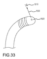
- FIG. 33 illustrates an incremental catheter movement vector
- FIG. 34 is an illustration of forward and inverse kinematic relationships
- FIG. 35 is an illustration of an embodiment of a forward kinematic relationship
- FIG. 36 is an illustration of an embodiment of an inverse kinematic relationship
- FIGS. 37 a - 37 b are schematic representations of a bendable portion of a catheter illustrating, respectively, a deflection angle and a heading angle;
- FIG. 38 is an illustration of a cross section of a catheter
- FIG. 39 is a representation of a catheter movement to accomplish a model registration
- FIGS. 40 a - 40 b are illustrations of compound catheter-sheath movement
- FIG. 41 is an embodiment of a catheter control diagram employing feedback
- FIG. 42 is an illustration of a catheter movement from which contact may be deduced.
- FIG. 43 is an illustration of a compound catheter-sheath movement for avoiding proximal obstructions.
- robotic catheter system 10 (described in detail below), also referred to as “the system,” may be likened to power steering for a catheter system.
- the system may be used, for example, to manipulate the location and orientation of catheters and sheaths in a heart chamber or in another body cavity. As shown in FIG.
- robotic catheter system 10 may generally incorporate a human input device and control system (referred to as “input control system”) 100 , e.g., a joystick and related controls, that a user such as an electrophysiologist (EP) may interact with, an electronic control system 200 that translates motions of the user at the input device into a resulting movement of a catheter tip, and a visualization system 12 that provides a user with real-time or near-real-time positioning information concerning the catheter tip.
- input control system e.g., a joystick and related controls
- E electrophysiologist
- visualization system 12 that provides a user with real-time or near-real-time positioning information concerning the catheter tip.
- the system may further include closed-loop feedback using an EnSite NavX system 14 , or similar positioning systems such as, for example, the gMPS system, commercially available from Mediguide Ltd., a robotic catheter manipulator assembly 300 for operating a robotic catheter device cartridge 400 and manipulator support structure 500 (described in detail below).
- EnSite NavX system 14 or similar positioning systems such as, for example, the gMPS system, commercially available from Mediguide Ltd., a robotic catheter manipulator assembly 300 for operating a robotic catheter device cartridge 400 and manipulator support structure 500 (described in detail below).
- the system provides the user with a similar type of control provided by a conventional manual system, but allows for repeatable, precise, and dynamic movements.
- An embodiment of robotic catheter system 10 may involve automated catheter movement.
- a user such as an EP, could identify locations (potentially forming a path) on a rendered computer model of the cardiac anatomy.
- the system can be configured to relate those digitally selected points to positions within a patient's actual/physical anatomy, and may command and control the movement of a catheter to defined positions. Once in position, either the user or system could then perform the desired treatment or therapy—which may further be in accordance with a defined algorithm.
- This system could enable full robotic control by using optimized path planning routines together with closed-loop position control.
- the system could automate certain “best-practices,” such as pulling the catheter across the surface, or making contact at an oblique angle.
- input control system 100 will be described briefly.
- the input control system 100 may generally allow a user to control the movement and advancement of both the catheter and sheath.
- input devices including, without limitation, instrumented traditional catheter handle controls, oversized catheter models, instrumented user-wearable gloves, touch screen display monitors, 2-D input devices, 3-D input devices, spatially detected styluses, and traditional joysticks.
- the input device may be configured to directly control the movement of the catheter and sheath, or may be configured to, for example, manipulate a target or cursor on an associated display.
- the joystick may be spring centering so that any movement from the center position causes an incremental movement of the actual catheter tip, or the joystick may work in absolute terms.
- Haptic feedback may also be incorporated to provide a user with a sense of when contact has been made.
- Such features may include, closed-loop feedback using an EnSite NavX system or gMPS system 14 for creating realistic cardiac chamber geometries or models, displaying activation timing and voltage data to identify arrhythmias, and guiding precise catheter movement, and/or optical force transducers; active tensioning of “passive” steering wires to reduce the system response time; cumulative ablation while the tip is following a front-to-back ironing motion; and/or reactive/resistive impedance monitoring.
- visualization system 12 will be described briefly.
- Visualization system 12 may provide a user with real-time or near-real-time positioning information concerning the catheter tip.
- system 12 may include an EnSite NavX monitor 16 or other similar monitor for displaying cardiac chamber geometries or models, displaying activation timing and voltage data to identify arrhythmias, and for facilitating guidance of catheter movement.
- a fluoroscopy monitor 18 may be provided for displaying a real-time x-ray image or for assisting a physician with catheter movement.
- Additional exemplary displays may include an ICE and EP Pruka displays, 20 , 22 , respectively.
- EnSite NavX system 14 will be described briefly.
- EnSite NavX system 14 (described in detail in U.S. Pat. No. 7,263,397, titled “Method and Apparatus for Catheter Navigation and Location and Mapping in the Heart,” incorporated by reference in its entirety) may be provided for creating realistic cardiac chamber geometries or models, displaying activation timing and voltage data to identify arrhythmias, and guiding precise catheter movement. EnSite NavX system 14 may collect electrical position data from catheters and use this information to track or navigate their movement and construct three-dimensional (3-D) models of the chamber.
- position data from the catheter may be obtained using a gMPS system, commercially available from Mediguide Ltd., and generally shown and described in U.S. Pat. No. 7,386,339 entitled “Medical Imaging and Navigation System,” which is incorporated herein by reference in its entirety.
- robotic catheter manipulator assembly 300 for operating robotic catheter device cartridges 400 will be described briefly.
- robotic catheter system 10 may include one or more robotic catheter manipulator assemblies 300 that serve as the mechanical control for the movements or actions of one or more robotic catheter device cartridges 400 .
- FIG. 1 illustrates a generally vertically oriented manipulator assembly 300 for minimizing approach angle
- FIG. 2 a illustrates a manipulator assembly 380 slightly angled from a generally horizontal position
- FIG. 2 d illustrates an embodiment where multiple manipulator assemblies can be used for a single procedure.
- FIGS. 3 a and 6 a - 6 c respectively illustrate first-fourth embodiments of assemblies 300 , namely assemblies 302 , 370 , 372 and 374 .
- Manipulator assembly 302 and its associated components will be described herein for facilitating an understanding of robotic catheter system 10 .
- the first embodiment of manipulator assembly 302 may respectively include both catheter and sheath manipulator mechanisms 304 , 306 .
- the catheter and sheath manipulator mechanisms 304 , 306 may be aligned such that the catheter can pass through the sheath in a coaxial arrangement.
- Each mechanism 304 , 306 may be further capable of independent advancement/retraction (shown generally as directions D 1 and D 2 ) and independent four-wire steering control (e.g., eight total steering wires, comprising four sheath control wires and four catheter control wires), as discussed in detail below.
- both the catheter and sheath may be capable of independent control
- the system may only provide for control of one device while allowing the other device to remain passive (e.g., the sheath is actively controlled while the catheter is passive or “along for the ride”). In a configuration where one passive device is used, it may not be necessary to include control wires in the passive device.
- a length of stiff material such as, for example, a solid metal rod or fiber reinforced composite, may be incorporated on the interior of the proximal portion of catheter 406 .
- catheter 406 may be proximally stiffened so that the length of the catheter proximally extending from sheath cartridge 404 is less likely to buckle during relative translation, as the entire length of catheter 406 extends into sheath 410 .
- robotic catheter manipulator assembly 302 Referring to FIGS. 1 and 3 a - 5 e , the first embodiment of robotic catheter manipulator assembly 302 will be described in detail.
- robotic catheter system 10 which includes one or more robotic catheter manipulator assemblies 300 , includes the first embodiment of robotic catheter manipulator assembly 302 including both catheter and sheath manipulation mechanisms 304 , 306 for manipulating, for example, catheter and sheath cartridges 402 , 404 .
- Manipulator assembly 302 may include interconnected/interlocking manipulation bases 308 , 310 for catheter and sheath cartridges 402 , 404 , and likewise may include electrical “handshake” functionality as discussed below.
- Each interlocking base 308 , 310 may be capable of travel in the longitudinal direction of the catheter/sheath (D 1 , D 2 respectively).
- D 1 and D 2 may each represent a translation of approximately 8 linear inches.
- each interlocking base may be translated by high precision drive mechanisms 312 , 314 .
- Such drive mechanisms may include, for example and without limitation, a motor driven lead screw or ball screw.
- an associated manipulation base 308 , 310 may include a plurality of fingers 316 , 318 , 320 and 322 , (e.g., one per steering wire) that extend or protrude upwardly to contact and interact with the steering wire slider blocks (such as slider blocks 412 , 414 , 416 , 418 ) to independently tension select steering wires 420 , 422 , 424 , 426 .
- Each finger can be configured to be independently actuated by a precision drive mechanism, such as a motor driven ball screw 324 , and may be outfitted with steering wire force sensors to measure corresponding steering wire tension.
- Each motor driven ball screw may further include encoders to measure a relative and/or an absolute position of each element of the system.
- bearing 332 and coupler 330 of ball screw 324 may engage frame 340 of respective bases 308 , 310 and a corresponding finger 316 , 318 , 320 or 322 may be mounted adjacent a strain gauge for measuring the corresponding steering wire tension.
- bases 308 , 310 may include exemplary components such as motors 342 , 344 , 346 and 348 , respectively coupled to fingers 316 , 318 , 320 and 322 .
- a bearing 354 may be provided for sliding of bases 308 , 310 on track 356 .
- a plurality of inductive sensors (e.g. home sensors) 358 may be provided for guiding each manipulation base to a safe position.
- Manipulator assembly 302 may be disposed in a vertical configuration (see FIG. 1 ) for minimizing both the approach angle of the catheter and the distance the catheter must extend from the patient, or slightly angled from a generally horizontal position (see FIG. 2 ).
- the approach angle and catheter extension distance may be minimized by vertically orienting the backplane of the manipulator head, with the interlocking cartridges positioned at the lower extreme such that they may travel nearly horizontally and substantially in line with the point of entry into the patient (e.g., as generally illustrated in FIG. 1 ).
- the positioning of the manipulator head structure may allow the proximal control of the catheter/sheath to be held closely to the patient's body without substantial structural interference.
- high-precision drive mechanisms 312 , 314 for translating each of the catheter and sheath cartridges 402 , 404 may be positioned generally below the manipulator bases 308 , 310 to allow the respective cartridges to be positioned toward the lower area of the manipulator. By holding a close distance, the ingress angle of the catheter/sheath may be minimized, and the manipulator control may be positioned more closely to an insertion site.
- manipulator assembly 302 may include a support device 382 positioned on the distal end of the manipulator assembly and configured to receive one or more ancillary tools, such as, for example, an introducer 384 , a guide 386 , or a hemostasis pad 388 .
- ancillary tools such as, for example, an introducer 384 , a guide 386 , or a hemostasis pad 388 .
- FIGS. 3 k - 3 m Various configurations of support devices and ancillary tools are illustrated in FIGS. 3 k - 3 m .
- the support device 382 and ancillary tools are configured to interact with a portion of the catheter and/or sheath between the manipulator and the patient. For example, as generally illustrated in FIGS.
- introducer 384 and/or guide tube 386 may direct the catheter into the patient at a fixed angle or position while allowing the manipulator to be oriented at a different relative angle.
- the support device 382 may include a hemostasis pad 388 .
- robotic catheter manipulator assembly 302 may be usable with a robotic catheter rotatable device cartridge 490 .
- manipulator base 308 may be replaced with a robotic catheter rotatable drive head 492 and a robotic catheter rotatable drive mechanism 494 .
- catheter and sheath cartridges 402 , 404 will be described in detail.
- robotic catheter system 10 may include one or more cartridges 400 , with manipulator 302 including at least two cartridges 402 , 404 , each of which may be respectively designed to control the distal movement of either the catheter or the sheath.
- catheter 406 may be substantially connected or affixed to cartridge 402 , so that advancement of cartridge 402 correspondingly advances catheter 406 , and retraction of the cartridge retracts the catheter. As further shown in FIGS.
- each cartridge 402 , 404 may include slider blocks (e.g., 412 , 414 , 416 , 418 ), each rigidly (and independently) connected or affixed to one of a plurality of catheter steering wires (e.g., 420 , 422 , 424 , 426 ) in a manner that permits independent tensioning of each steering wire.
- the cartridge may be provided as a disposable item that is capable of being easily positioned (e.g., snapped) into place in an overall assembly.
- the cartridge may include an electrical “handshake” device or component to allow the system to properly identify the cartridge (e.g., by type and/or proper placement/positioning).
- Sheath cartridge 404 may be designed in a similar manner as the catheter cartridge 402 , but will typically be configured to provide for the passage of catheter 406 .
- Assembly 302 may include a plurality (e.g., as many as ten or more) of independent driving mechanisms (e.g. motor driven ball screws 324 ).
- the catheter and sheath cartridge can be designed to be substantially similar, and in that context a reference to either may relate to both.
- the design of the catheter/sheath cartridge may include upper and lower cartridge sections 428 , 430 , and independent slider blocks 412 , 414 , 416 , 418 .
- the system is not generally limited to specific material selection or formation techniques.
- the upper and lower cartridge sections 428 , 430 may be injection molded using a polycarbonate material.
- Each slider block 412 , 414 , 416 , 418 may be connected to a separate catheter steering wire 420 , 422 , 424 , 426 , and may be formed of a Teflon-like material such as, for example, Delrin AF.
- Teflon-like slider blocks When in contact with the cartridge housing portions 428 , 430 , such Teflon-like slider blocks may maintain a low static and dynamic coefficient of friction and may avoid the need for additional lubrication.
- catheter and sheath cartridges 402 , 404 may be configured to secure or lock down onto respective interconnecting catheter and sheath manipulation bases 308 , 310 .
- one or more locking pins e.g., 432 in FIGS. 5 a , 5 d and 5 e
- such recesses 360 may include an interference lock such as a spring detent or other locking means.
- such other locking means may include a physical interference that may require affirmative/positive action by the user to release the cartridge. Such action may include or require actuation of a release lever 362 .
- cartridge 402 (and 404 ) may include one or more locator pins 434 that are configured to passively fit into mating holes on the base (e.g., 364 in FIG. 4 a ).
- a user may first manually position catheter 406 and sheath 410 (with catheter 406 inserted in sheath 410 ) within the vasculature of a patient. Once the devices are roughly positioned in relation to the heart, the user may then engage or connect (e.g., “snap-in”) the catheter cartridge into place on interconnecting/interlocking bases 308 , 310 of manipulator assembly 302 , for example, by inserting the locking/locating pins 432 , 434 of the cartridges into mating holes 360 , 364 of respective base 308 , 310 .
- each of the plurality of fingers 316 , 318 , 320 or 322 may fit into recesses formed between the distal edge of slider blocks 412 , 414 , 416 , 418 and a lower portion of the cartridge housing. Such recesses are shown in, for example, FIGS. 5 d and 5 e.
- Each finger may be designed to be actuated in a proximal direction to correspondingly push each respective slider block.
- the slider block can be configured to force the finger to self center on its geometry when contact is first made. Such a centering feature may be facilitated by the contact surface of the slider block.
- the slider block may include an engagement surface (e.g., shaped as a semi-cylindrical recess in the forward facing portion). This surface may be configured to mate or communicate with a matching round portion of a corresponding finger.
- Robotic catheter system 10 may be useful for a variety of procedures and in connection with a variety of tools and/or catheters.
- tools and/or catheters may include, without limitation, spiral catheters, ablation catheters, mapping catheters, balloon catheters, needle/dilator tools, cutting tools, cauterizing tools, and/or gripping tools.
- the system may additionally include a means of identifying the nature and/or type of catheter/tool cartridge that is installed for use, and/or position or connection related information.
- the system may automatically access/obtain additional information about the cartridge, such as, without limitation, its creation date, serial number, sterilization date, prior uses, etc.
- each cartridge may contain a chip (e.g., an EEPROM chip) that can be electrically interfaced by the manipulator head.
- a chip e.g., an EEPROM chip
- Such a chip could, for instance, be programmed during the manufacturing process and may electronically store various data, such as the make; model; serial number; creation date; and/or other special features associated with the cartridge or tool.
- the chip may contain other worthwhile information, such as an indication of previous use, catheter specific calibration or model data, and/or any other information that may relate to the safety or performance of the particular device.
- a detection means such as an optical or magnetic sensor, may initially detect the presence of the cartridge. Once presence is detected, the manipulator may energize a chip and initiate data/signal retrieval. Such retrieved data/signal may then be used by the system to control or alter various features and/or displays based on the type of device and/or information provided. While one embodiment may use a chip (e.g., EEPROM), due to its design flexibility, another embodiment may include a wireless transmission device, such as an RFID, which may be employed to facilitate the data storage/transfer instead of, or in addition to a chip.
- a chip e.g., EEPROM
- RFID wireless transmission device
- manipulator support structure 500 various embodiments are disclosed.
- Manipulator support structure 510 may generally include a support frame 512 including retractable wheels 514 and attachment assembly 516 for attachment to operation bed 518 .
- a plurality of support linkages 520 may be provided for accurately positioning one or more robotic catheter manipulator assemblies 300 / 302 .
- manipulator support structure 510 may be wheeled to operation bed 518 and attached thereto by attachment assembly 516 .
- FIG. 2 d illustrates an embodiment where multiple manipulator assemblies are provided on a common manipulator support structure 510 .
- a second manipulator 301 may be identical to the first manipulator 300 , though may include cartridges 403 and 405 that are designed to perform different tasks than the cartridges 402 , 404 on the first manipulator 300 .
- each manipulator 300 , 301 may be used together during a single procedure.
- each manipulator may control a catheter extending through a different anatomical lumen.
- one catheter may extend into the left femoral vein, while another catheter may extend through the right femoral vein.
- one or more catheters may extend through the right or left subclavian or internal jugular veins.
- each manipulator 300 , 301 may control the positioning of one or more distal tools, where the tools may be similar or different in nature.
- two manipulators may control the positioning of two ablation electrodes.
- one manipulator e.g., manipulator 300
- a second manipulator e.g., manipulator 301
- the system may be configured to test the effectiveness of an isolation procedure by using one manipulator to stimulate tissue, while a second manipulator is configured to measure transmitted impulses (or lack thereof). It should be understood that any combination of ablation, mapping, stimulation, ultrasound, cautery, or surgical tips may be used in conjunction with any of the one or more manipulators.
- Manipulator support structure 550 may generally include a support frame 552 including retractable wheels 554 and attachment assembly 556 for attachment to operation bed 518 .
- a plurality of support linkages 558 may be provided for accurately positioning robotic catheter manipulator assembly 300 .
- a handle 560 may be provided for assisting a user with extending attachment assembly 556 to an opposite side of bed 518 .
- manipulator support structure 550 may be wheeled to operation bed 518 and attached thereto by attachment assembly 556 . Thereafter, wheels 554 may be pivoted upwards upon release by a step-pedal system 562 to be positioned out of the path of operating personnel.
- Manipulator support structure 600 may generally include a portable unit 602 for transportation of manipulator support structure 600 and its related components.
- Structure 600 may include attachment assembly 604 for attachment to operation bed 518 , and a plurality of support linkages 606 for accurately positioning robotic catheter manipulator assembly 300 .
- manipulator support structure 600 may be wheeled to operation bed 518 and attached thereto by attachment assembly 604 , and thereafter detached and placed in portable unit 602 for transportation.
- Manipulator support structure 650 may generally include a track mounted unit 652 for movement of manipulator support structure 650 and its related components. Structure 650 may include attachment assembly 654 for attachment to ceiling or otherwise mounted track 656 , and a plurality of support linkages 658 for accurately positioning robotic catheter manipulator assembly 300 .
- manipulator support structure 650 in use, may be positioned relative to operation bed 518 and locked in position during use, and moved out of the use position or otherwise re-configured to a stowed position by re-positioning of support linkages 658 . As shown in FIG. 9 b , manipulator support structure may be moved generally horizontally and vertically for positioning and removal from the area of operation bed 518 .
- Manipulator support structure 700 may generally include a fixed unit 702 for movement of manipulator support structure 700 and its related components. Structure 700 may include attachment assembly 704 for attachment to the floor, and a plurality of support linkages 706 for accurately positioning robotic catheter manipulator assembly 300 . In use, manipulator support structure 700 may be mounted in place relative to operation bed 518 , or alternatively, bed 518 may be positioned adjacent structure 700 . After use, structure 700 may be re-configured to a stowed position by re-positioning of support linkages 706 .
- Manipulator support structure 750 may generally include a portable unit 752 for movement of manipulator support structure 750 and its related components.
- Structure 750 may include a pivotable support 754 for accurately positioning robotic catheter manipulator assembly 300 .
- Pivotable support 754 may be pivotable about generally vertical and horizontal axis 756 , 758 .
- a disposable sterile shield 760 may be positionable on robotic catheter manipulator assembly 300 .
- Sterile shield 760 may isolate the manipulator from a sterile field in an operating room/EP lab environment.
- the sterile interface may optionally include a sealing material or component, such as a pliable gasket-type material, to allow the manipulator fingers (e.g. 316 , 318 , 320 and 322 ) to interact with the cartridge (e.g. 402 , 404 ) without operational interference, but while maintaining a necessary degree of sterility.
- a sealing material or component such as a pliable gasket-type material
- Such a barrier or drape may permit the manipulator to be re-used without requiring additional sterilization.
- manipulator support structure 750 may be placed next to operation bed 518 , or alternatively, bed 518 may be positioned adjacent structure 750 , with an appropriate sterile shield 760 disposed on robotic catheter manipulator assembly 300 .
- structure 750 may be collapsed as shown in FIG. 11 f .
- cartridges 402 , 404 may be attached or replaced as needed by access via a hinged cover of manipulator case 764 , or alternatively, as shown in FIG. 11 h , a sectioned case 766 may be provided for cartridge replacement or access to robotic catheter manipulator assembly 300 .
- Manipulator support structure 800 may be similar in design to support structure 550 of FIGS. 7 a and 7 b .
- Manipulator support structure 800 may generally include a support frame 802 including wheels 804 and attachment assembly 806 for attachment to operation bed 518 .
- a plurality of support linkages 808 may be provided for accurately positioning robotic catheter manipulator assembly 300 .
- a touch-screen interface 810 may be provided for controlling operation of robotic catheter manipulator assembly 300 .
- manipulator support structure 800 may be wheeled to operation bed 518 and attached thereto by attachment assembly 806 .
- Manipulator support structure 850 may be similar in design to support structure 550 of FIGS. 7 a and 7 b .
- Manipulator support structure 850 may generally include a support frame 852 including wheels 854 and attachment assembly 856 for attachment to operation bed 518 .
- a plurality of support linkages 858 may be provided for accurately positioning robotic catheter manipulator assembly 300 . As shown in FIG. 13 a , and FIGS.
- a disposable cover 860 may be provided for robotic catheter manipulator assembly 300 , with the cover being used with any of the embodiments of manipulator support structures disclosed herein.
- disposable covers 860 and 862 may include a two part top and bottom cover 864 , 866 , with a saline bag attachment loop 868 and integrated handle 870 . As shown in FIGS. 13 d - 13 f , disposable covers 860 and 862 may include a two part top and bottom cover 864 , 866 , with a saline bag attachment loop 868 and integrated handle 870 . As shown in FIGS.
- cover 872 may be collapsible for permitting use of robotic catheter manipulator assembly 300 by exposing catheter/sheath 874 .
- a cover 876 may be opened and removed to permit unrestrained operation of manipulator assembly 300 .
- FIG. 13 o another transportation system for the aforementioned manipulator support structures and related components is illustrated.
- Manipulator support structure 900 may generally include a support frame 902 including retractable wheels 904 and releasable attachment assembly 906 for attachment to operation bed 518 .
- a plurality of support linkages 908 may be provided for accurately positioning robotic catheter manipulator assembly 300 .
- manipulator support structure 900 is illustrated as respectively disposed in the use and stowed/transport configurations. As shown in FIGS.
- manipulator support structure 900 may be wheeled to operation bed 518 and attached thereto by attachment assembly 906 . Thereafter, wheels 904 may be pivoted upwards upon release by a step-pedal (not shown) to be positioned out of the path of operating personnel.
- manipulator support structure 900 may include a sterile cover 910 disposed over manipulator assembly 300 .
- Other components may include irrigation tubes 912 , a USB/power connector 914 , and a control module 916 including a power port, network port and an EnSiteTM system connection.
- Saline bags may be removably hung at hangers 918 , and a foldable shelf 920 may be provided for equipment, such as, a saline pump and/or ablation generator 922 .
- manipulator assembly 300 including sterile cover 910 may further include power on/off switches 924 , 926 , and an emergency power switch 928 .
- the manipulator and cartridge electrical/control connections may be provided at 930 , 932 .
- a handle 934 may be used to maneuver manipulator assembly 300 as needed.
- Appropriate LEDs 936 , 938 may be provided for indicating proper connection of the catheter and sheath cartridges.
- manipulator assembly 300 may be pivotally connected to support linkages 908 at pivot point 940 by a two point rigid connection 942 including fasteners 944 and washer/aligner 946 .
- cartridges 400 may include a cut-out 950 sized for a resistance snap-fit onto detent 952 of a manipulation base.
- a release button 954 may be provided for release of the cartridges from manipulator assembly 300 .
- cartridges 400 may include a flexible connection for the catheter/sheath at strain relief connection 956 , and electrical connection 968 .
- an ergonomic grip area 958 may be provided for facilitating attachment, detachment and grasp of the cartridges. Referring to FIG.
- each cartridge may include a guide keel 960 including control pin slots 962 and control detent 964 engageable with respective detents and slots in the manipulation base (see FIG. 14 g ).
- a sterile cap 966 may be provided for storage and transport of the cartridges, and removal of the cap for use.
- the aforementioned articulated support structures may hold manipulator assembly 300 in a position to better facilitate treatment or therapy (e.g., adjacent the femoral vein/artery to promote catheterization).
- Such support structures discussed in reference to FIGS. 2 a - 14 j may, without limitation, include joints that may include a gas or hydraulic assist on each joint, and may further include a braking mechanism to decelerate or lock any moving component in place.
- the gas-hydraulic assist mechanisms may be provided on all joints to aid in vertical or other motion of the manipulator assembly.
- electronic or electro-mechanical braking may be provided on all joints and at all degrees of freedom.
- the brake(s) may be configured to default to a locked state so that power is needed to enable any motion.
- a normally-locked configuration may be provided so that momentary power loss will not cause any unlocking or joint movement.
- the system may also be designed with sufficient stability to prevent movement, even under minor impacts.
- an embodiment of robotic catheter system 10 can include a user input device 1000 .
- the user input device 1000 may be a two or three dimensional input device that can be used to spatially manipulate a displayed catheter or a displayed target.
- Such an interface may be akin to, for example, a traditional computer mouse, a flight joystick, a three dimensional joystick, a 3D mouse, such as those commercially available from 3Dconnexion, a Falcon joystick from Novint Technologies Inc., a touch-screen monitor, or a spatially detected stylus.
- the interface device may allow a user to provide input to the system in a manner mimicking traditional catheter handle controls.
- an embodiment of the user input device 1000 may provide instrumented sheath and catheter handles 1002 , 1004 (or vice-versa), respectively, that are able to longitudinally translate (e.g., in directions D 3 and D 4 ), independently rotate (in directions R 1 and R 2 ), and/or include one or more movable thumb tabs (e.g., elements 1006 , 1008 ).
- each degree of movement may be instrumented, for example, with a potentiometer or motor/encoder.
- an embodiment of robotic catheter system 10 may be configured such that longitudinally translating the input handle may cause a respective longitudinal translation of the catheter/sheath distal tip.
- the automated catheter system would generally effectuate this translation by advancing or retracting the cartridge.
- robotic catheter system 10 can be configured so that the rotation of either handle causes a virtual rotation of the catheter/sheath tip, and movement of a thumb tab causes a deflection in the current deflection plane.
- any or all motion controls of the device can be associated with/employ a spring centering feature that returns each control element to a set or “home” location after the element is released.
- a centering feature can allow for highly precise movement corrections of the distal tip by registering various input movements as incremental movement from the “home” location rather than by registering movement entirely in absolute terms.
- user interface device 1000 may additionally include or substitute displacement dial controls. Furthermore, to suit the desires of the user, an embodiment of such a user interface device may permit the handles to be fully interchangeable so that various combinations of controls (e.g., dial and thumb tab handles) can be used for catheter/sheath input.
- user interface device 1000 may further include safety buttons (e.g. “dead-man switches”) that must be pressed for any joystick movement to be registered by the system. This design would prevent inadvertent motion from affecting the position of the actual catheter tip.
- user interface device 1000 may further include a virtual reality surgical system, wherein the physician could be positioned within a cardiac environment (see FIG. 1 ), and physically position the catheter where desired or needed.
- the physical construction of another embodiment of the user interface device 1000 may be similar to that of an actual catheter, though on a different scale.
- the various sections may be constructed with pull wires, wire ducts, and variable stiffness sections 1010 , 1012 , 1014 associated with a conventional catheter.
- all motions of this device may be configured with a centering feature (e.g., a spring centering mechanism 1016 ), wherein the device inherently returns to an initial position when released. This configuration may be useful or suitable for an incremental input control scheme.
- the device may be constructed without a centering mechanism, where the absolute position of the device might instead be used to control the absolute position of the actual sheath and catheter.
- the input device's physical limitations may be designed to mimic an actual catheter's and sheath's physical limitations (e.g., movement restrictions based on bend radius, catheter retracted into sheath, etc.).
- each degree of movement can generally be instrumented with either a potentiometer or motor/encoder. If a motor/encoder is used, the system may also provide haptic feedback upon certain events—such as a “feel” if the catheter were to contact a virtual wall.
- An embodiment of this invention may also include an ablation activation button on the distal end of the device.
- the user input device 1000 may include a 2D or 3D input device, such as a mouse or 3D joystick.
- the user input device 1000 may include a spatially detected glove or stylus as generally illustrated in FIGS. 18 a - 18 b.
- the user input device 1000 includes a spatially detected glove, such as generally illustrated in FIG. 18 a
- the user's/wearer's index finger may be instrumented with various sensors 1040 (e.g., position and orientation sensors, and/or accelerometers).
- the user may have the ability to manipulate the actual catheter tip by moving his/her instrumented finger.
- a stylus 1050 may be substituted for the user's index finger, where the stylus 1050 is similarly instrumented with sensors 1052 configured to measure, for example, position, orientation, and/or acceleration.
- the user may be presented with a three dimensional visualization of the catheter and/or heart anatomy, such as through holographic imagery.
- the user may manipulate or interact with a visualization of the catheter, for instance, by moving the actual device within the holographic image.
- the real-time catheter position may be configured to track the three dimensional position of the user's index finger or stylus.
- the spatial positioning of the glove 1040 or stylus 1050 may be detected in three dimensional space and registered to a representation of a catheter or a target located within a model of the patient's anatomy 1060 .
- the catheter representation within the model 1060 may be configured to be displayed to the user on a two-dimensional monitor 1062 .
- the user may control the movement of the catheter representation, which is in turn configured to control the movement of the actual catheter.
- an incremental movement control scheme may be implemented by incorporating an activation switch, such as, for example, a foot pedal 1082 .
- the actuation switch may indicate to the system that successive movements should be recorded or registered within the system for the purpose of control.
- the glove or stylus input device may be locatable in 3-D space through the use of a positioning system employing a magnetic field, an electrostatic field, or through the use of an optical positioning system.
- a positioning system employing a magnetic field, an electrostatic field, or through the use of an optical positioning system.
- These systems may include, for example, the EnSite NavX system from St. Jude Medical, the gMPS system from Mediguide, the CARTO system from Biosense Webster, the Aurora system from Northern Digital, or the RMT system from Boston Scientific.
- the positioning system may be implemented within a liquid tank (e.g., water tank), where field generators (such as those associated with the St. Jude Medical NavXTM control system) are externally attached.
- a liquid tank e.g., water tank
- field generators such as those associated with the St. Jude Medical NavXTM control system
- an instrumented glove or stylus may extend into the tank while, for example, user's finger (e.g., index finger), or stylus may be instrumented with electrodes configured to measure parameters of the electric field.
- the construction and/or placement of the sensors e.g., NavX-type electrodes
- the construction and/or placement of the sensors may be similar to sensors on the distal portion of the catheter.
- the positioning system may be implemented using a magnetic positioning system.
- a magnetic positioning system 1070 may operate, for example, by emitting several magnetic fields 1072 a - 1074 c from an array of field generators 1074 a - 1074 c .
- Sensor coils e.g., sensors 1040 or 1052
- a processor 1080 may be able to resolve the sensor's position and orientation relative to each field generator or to a fixed reference sensor. Detected changes in the position and orientation of the glove or stylus sensor may then be registered and scaled by the system as a movement of a displayed catheter.
- a user interface device in the form of a touch screen monitor will now be discussed with reference to FIGS. 19 a - 19 d
- An embodiment of user interface device may include a multi-touch display interface 1100 and related hardware and software that would allow a user to physically interact with the robotic catheter system without the need for a keyboard, mouse, or other input device.
- a display may be configured to recognize multiple finger or hand contacts with or along the screen, and would allow a user to directly interface with the objects, anatomy, or devices displayed on the screen.
- an embodiment of the multi-touch interface 1100 may include multiple on-screen menu buttons 1102 that allow a user to toggle between various active functions within the image.
- Such functions may include, for example, the ability to pan, rotate, or zoom 3D objects and models within the display, select and/or direct movement of the catheter or sheath, place lesion markers, way points, virtual sensors, or automated movement targets and lines within the anatomic model.
- a user when in rotate mode, may rotate a 3D cardiac geometry 1104 by touching the screen with a finger and dragging across the screen to spin the 3D model about an axis orthogonal to both the surface normal of the screen and the direction of the dragging motion.
- a dragging motion across the screen may physically move the model across the screen.
- the zoom may be controlled, for example, through a pinching (zoom out) or expanding motion (zoom in) of multiple fingers, or through the use of an on-screen slider
- the multi-touch interface 1100 may be used to control the movement of a displayed catheter 1110 or sheath 1112 by first pressing on the image of the catheter or sheath to select it, followed by dragging the selected device in the direction of intended travel.
- the catheter 1110 or sheath 1112 may be selected by using a pinching motion as if the user is virtually grabbing the image.
- a ghost image 1114 of the current position of the device may be displayed as a reference.
- the ghost image 1114 may be based on real-time feedback of the actual catheter position as provided by a catheter positioning system such as Ensite NavX.
- the user may release the selected catheter or sheath by removing his/her finger from the screen.
- the system may then be configured to move the actual catheter in accordance with the user intended motion, and may update the ghost image 1114 to reflect the actual movement.
- the user may move a control point on the catheter or sheath and the actual catheter may be configured to track this point in real-time.
- the user may use the multi-touch interface 1100 to select target points 1120 within the image.
- These target points may be used to identify lesion points for intended or completed therapy delivery, way-points for semi-automated step-wise catheter movement, destination points for fully automated movement, or as relative markers or virtual electrophysiology sensors that may have no impact on relative movement.
- a target point may 1120 be initially set by taping on screen in a position where a target point is desired. Once a point has been set, it may be subsequently selected by re-tapping on the point. When a point is “selected,” it may change appearance, such as selected point 1122 .
- the user may for example, select it by tapping it, and then drag the point to a new location. Additionally, after selecting a point, the software may call up a list of menu options that may allow the user to configure or view one or more parameters of the point.
- parameters may include, for example, the nature of the point (e.g. marker, lesion point, waypoint, sensor) the distance of the point above the surface, or specific data recorded or computed at the point.
- the software may be configured to place the target point 1120 directly on the surface of the model 1104 as displayed.
- the system may know the relative depth of each pixel or primitive on the display. By touching on a displayed element, the system may map the target point directly to the anatomical surface.
- the software may further allow the user to specify a fixed or minimum distance from the displayed anatomical surface where the point should be located. For example, if the user specifies a distance of 10 mm prior to selecting a point, the software may locate the target point 10 mm off of the selected surface in a direction normal to the screen/viewing plane.
- the software may generate a virtual surface located 10 mm interior to the surface of the anatomical model and then map the point to the virtual surface. (i.e. 10 mm normal to the anatomical model surface).
- the user may select a point 1122 with one finger 1124 , and use a second finger 1126 to control a variable slider 1128 to specify a distance above the surface.
- the slider 1128 may likewise be located on the side of the screen and/or may appear only after a point has been selected.
- the display may also be configured to display a secondary projection of the catheter and model to aid the user in positioning the target point in three dimensional space (e.g. using a right anterior oblique (RAO) projection as the primary display, and a left anterior oblique (LAO) projection as the secondary display).
- REO right anterior oblique
- LAO left anterior oblique
- the user may use a second finger to modulate a slider (such as a slider generally illustrated in FIG. 19 c ) to control the catheter's distance from the anatomical surface in real time.
- a slider such as a slider generally illustrated in FIG. 19 c
- the user could achieve a motion where, for example, the catheter begins in contact with the tissue, gradually lifts off from the tissue while traversing a distance, and gradually lands back on the tissue.
- the user may use a physical slider or wheel, apart from the display, to modulate the distance from the surface.
- the user may also control the extension of the catheter from the sheath by placing one finger on the catheter 1112 and a second finger on the sheath 1114 and expanding or squeezing his/her fingers together.
- the user may also be able to specify a line or path 1130 along the surface of the model 1104 by touching and dragging a finger across the screen.
- Such generated line 1130 may be similar to a splined series of waypoints.
- the user may select a point along the line and “lift” that point away from the surface by, for example, using a slider or numerical input. Points adjacent to the selected point may additionally be lifted off as if they were tied to the selected point.
- the multi-touch interface 1100 may be used to manage multiple displays (such as displays A-D) in an integrated electrophysiology environment.
- Using the interface for display management purposes may include the ability to resize, move, minimize, or maximize windows that display, for example, EnSite NavX models, digital fluoroscopic displays, patient vital information, patient hospital records, real time electrocardiograph traces, CT imagery, MRI imagery, and/or any other displays desired by the user.
- a user may move or expand a window using on-screen buttons to, for example, freeze the touch screen input for the respective displays, followed by touching and dragging the window to move it, or using a multi-finger expanding motion to, for example, expand the window.
- the user input may be obtained through a spatial operating environment that is configured to monitor hand or body gestures without any required direct contact with a screen or device.
- the interface may operate together with either a two dimensional display or a three dimensional holographic image, and may allow the user to selectively manipulate, for example, the catheter or sheath, the cardiac model, various markers or waypoints within the model, or the positioning of other informational windows or displays.
- Such a gestural interface may include, for example the “G-Speak” Spatial Operating Environment, developed by Oblong Industries, Inc.
- An embodiment of user interface device 1000 that incorporates movement of a physical input device may include touch-type feedback, often referred to as “haptic feedback”
- This type of feedback may involve forces generated by a motor connected to user interface device 1000 that the user can feel while holding the device. These forces may be based on actual or computed forces being applied to a physical catheter tip.
- the unit may sense forces using a force and/or impedance sensor in the tip of the catheter and generate a corresponding force on an input handle.
- the forces can be based on a computed geometric model of the cardiac anatomy, such as that associated with the St. Jude Medical, Inc. EnSiteTM system.
- haptic feedback may be conveyed to a user by employing an input device instrumented with motors/encoders on each degree of freedom.
- the motors may operate in a passive mode for a majority of the procedure, if feedback is required by the system, the motors may be energized to produce a torque on the input controls capable of retarding the user's movement in particular degrees of freedom. While in a passive mode, the motor typically will not produce a significant retarding force, however the attached encoder may record the input for use in visualization and control routines.
- the system may first calculate the appropriateness and magnitude of such a force.
- a force may attempt to replicate a contact between an actual catheter tip and a portion of the cardiac anatomy.
- such contact may be either directly sensed through one or more force sensors on the distal tip of the catheter/sheath, or may be calculated based on a virtual catheter/sheath position within a rendered geometric computer model.
- the catheter's distal tip may be instrumented with a force sensor configured to provide an indication when physical contact is detected.
- a force sensor may include, without limitation, load cells, shape memory alloy based force sensors, piezoelectric force sensors, strain gauges, or optical-based or acoustic-based force sensors.
- a contact sensor that may be used is described in detail in U.S. patent application Ser. No. 11/941,093 entitled “Optic-Based Contact Sensing Assembly and System,” which is incorporated by reference in its entirety.
- a contact or proximity sensor may be used, such as those associated with detected electrical impedance.
- the senor may generate a signal representative of the actual physical or electrical contact. Based on the magnitude and direction of the sensed force, as well as the current position of the input device, the system may produce a corresponding torque or force on the input device that may resist further movement through the obstructing anatomy. The system can be configured so that the user would feel this reaction force as if the input device was impacting a “virtual wall.”
- the resistive force the user feels at the input joystick could be more or less “spongy.” That is, the system could be tuned so that a tip impact with the cardiac wall is either felt like a rigid impact with an immovable object, or perhaps as a contact with a soft sponge.
- haptic feedback forces may be conveyed to a user based on contact forces computed from the proximity between a virtual catheter model and a computer-generated representation of the cardiac anatomy.
- the positioning of the virtual catheter model may be obtained through an impedance-based position detection system (e.g., such as associated with St. Jude Medical's NavXTM system), or through a magnetic-based position detection system (e.g., such as associated with Mediguide's gMPS positioning system).
- a computer-generated representation of the cardiac anatomy may be derived from prior CT or MRI data, or a model (such as that created or maintained by St. Jude Medical's EnSiteTM system).
- a user may have a previously obtained geometric model of the cardiac anatomy.
- This model may be visible to an electrophysiologist user through a visualization system (such as St. Jude Medical's EnSiteTM system).
- This model may be assembled using, for example, previously captured CT or MRI images, and/or “skinned” geometry obtained by sensing actual position data of a mapping catheter (e.g., with St Jude Medical's NavXTM system or the gMPS system).
- a catheter locating system e.g., St. Jude Medical's NavXTM System or the gMPS system
- a haptic system could be used to compare the positioning of the catheter to that of the generated geometry. If the catheter is perceived to be in contact with the generated geometry, a resistive force could then be generated in connection with the associated input device—e.g., using attached motors.
- the geometric model may be registered to a repeating physiological signal such as, for example, the cardiac rhythm or respiration rhythm. As this signal is sensed in the actual procedure, the model geometry may dynamically change. This may then enable computed haptic feedback to provide a more accurate representation of the contact actually occurring within the patient.
- a repeating physiological signal such as, for example, the cardiac rhythm or respiration rhythm.
- a thumb switch on the catheter handle causes catheter deflection by tensioning a corresponding steering wire.
- Such a switch typically allows the distal tip of a catheter to laterally deflect in one of two opposing directions in a single plane. If deflection is desired in more than one plane, a user commonly must physically rotate the catheter about its longitudinal axis to cause the deflection plane to rotate.
- an indicator may be provided within a computer visualization to give the user an idea of which direction the distal tip will deflect if the deflection thumb switch is actuated.
- a representation e.g., deflection plane vector
- such a representation may include an arrow superimposed near the tip of the virtual representation of a physical catheter. Such an arrow may indicate the direction the catheter would move if the thumb switch were pulled toward the user.
- pushing a control e.g., thumb switch
- the user may then cause a rotation of this vector by rotating an input handle, which may then be sensed by the attached motor/encoder or potentiometer.
- a deflection vector could be associated with sheath visualization.
- the catheter 1210 may include at least two steering wires 1218 , 1220 , each longitudinally situated within and along a substantial length of the catheter 1210 .
- the steering wires 1218 , 1220 may be comprised of a material having a high elastic modulus—such as, for example, steel or aluminum.
- the catheter 1210 may further include a pull ring 1222 , which may take the form of a rigid ring firmly connected or affixed within a portion of the distal portion 1212 of the catheter 1210 .
- Each steering wire may be rigidly connected to pull ring 1222 , for example, via a rigid connection or coupling 1224 , 1226 .
- a rigid connection or coupling may comprise a weld, braze, or other known means of attachment.
- proximal portions of the steering wires 1218 , 1220 may be respectively connected to control members 1228 , 1230 .
- Control members 1228 , 1230 may be, for example, slider blocks such as those mentioned above, and may be used to interface or operatively connect control devices, such as the fingers of the manipulator assembly, to the steering wires 1218 , 1220 .
- control members 1228 , 1230 may both be situated at a one or more initial or common reference levels or datum (e.g., common datum X shown in FIG. 20 ).
- no initial relationship of control members 1228 , 1230 is necessary, and the positioning of each may, for instance, simply be a consequence of initial assembly.
- the distal portion 1212 of catheter 1210 may be deflected or displaced away from longitudinal axis L by selective actuation or tensioning of one or more steering wires.
- control member 1228 may be translated in a proximal direction a distance ⁇ X 1 , which causes a tension response in steering wire 1218 .
- the actuation of steering wire 1218 causes a corresponding deflection of the bendable section (i.e. the portion of catheter 1210 between fulcrum point 1236 and pull ring 1222 ) in a direction toward steering wire 1218 .
- the fulcrum 1236 generally defines the point along the length of the catheter at which the catheter 1210 transitions from a stiffer, proximal portion, to a more bendable, distal portion. In an embodiment, such increased bendability may be caused by using a material of a lesser durometer in the distal portion than in the proximal portion of the catheter.
- the fulcrum point 1236 may define a transition point of the catheter where the internal structure of the catheter is modified in a manner known in the art to promote distal bending.
- control member 1230 reactively moves or retracts a distance ⁇ X 2 in a second, substantially opposing distal direction.
- the reactive motion of control member 1230 and steering wire 1220 may depend on the difference in arc lengths between the two steering wires within the bendable section of the catheter. Assuming the distal portion bends with a constant radius of curvature, the arc lengths of the steering wires would then be a function of a transverse distance—e.g., distance T between steering wire 1218 and the central longitudinal axis L—and the bending radius of curvature of the distal portion 1212 . While, theoretically, displacements ⁇ X 1 and ⁇ X 2 can bear a linear relationship to each other, non-uniform axial compression of catheter 10 can cause the relationship between ⁇ X 1 and ⁇ X 2 to be non-linear.
- a user could, for example, actively translate control member 1230 in a proximal direction. Such a motion could cause the distal portion 1212 to rotate and deflect toward steering wire 1220 , while control member 1228 would be reactively translated in a distal direction.
- control members 1228 , 1230 may not necessarily return to their original positions (e.g., on datum X).
- FIGS. 20-21 illustrate the operation of a catheter having two steering wires oriented in a planar configuration
- other embodiments may include three or more steering wires that may cause three dimensional motion of the distal portion of the catheter.
- FIG. 22 generally shows an axial cross-section of a catheter embodiment, taken at the fulcrum point, that includes four steering wires 1240 a , 1240 b , 1240 c , 1240 d . While this illustration displays all steering wires spaced approximately 90 degrees apart, various other configurations may be provided.
- the respective tensioning of adjacent steering wires may cause a deflection of the distal portion 1212 of catheter 1210 in a unique direction, e.g., direction D.
- the distal portion of the catheter can be made to traverse circles of varying radii about longitudinal axis L (as viewed transverse to the page).
- the embodiment illustrated in FIG. 22 is similar to the two-steering wire embodiments shown in FIGS. 20-21 , since, when any wire or wires are actively tensioned, the opposing wires is permitted to reactively move a distance in an opposing distal direction. For example, as shown in FIG.
- steering wires 2 and 3 may be positively tensioned, while steering wires 1 and 4 ( 1240 a , 1240 d ) would move reactively.
- the catheter may include multiple bendable sections (e.g., sections 1310 , 1320 ), each having a separate pull ring (e.g., pull rings 1330 , 1340 ), fulcrum point (e.g., fulcrum points 1350 , 1360 ), and associated steering wires coupled with each pull ring.
- the inclusion of multiple bendable sections may allow a user to achieve compound bending postures with only a single device.
- the catheter may include a first bendable section 1310 and second bendable section 1320 that are capable of independently directed bending motions. In other embodiments, the catheter may include three or more bendable sections.
- each bendable sections has a proximal fulcrum point 1350 , 1360 , a pull ring 1330 , 1340 located distal to the fulcrum point, and a set of steering wires attached to the pull ring.
- the steering wires for both sections extend from the proximal end of the catheter, through the body of the catheter, and are affixed to the respective pull rings, as shown in FIG. 23 c .
- the fulcrum point for the second bendable section may be located at the pull ring for the first bendable section, as shown in FIG. 23 c .
- the fulcrum point may be located distal to the first pull ring.
- each of the six steering wires may be coupled with a respective slider block (e.g., slider blocks 1380 , 1382 , 1384 , 1386 , 1388 , 1390 ) within a proximal cartridge 1392 .
- the cartridge 1392 may, in turn, be configured to interface with a robotic manipulator 1394 , as shown, for example, in FIGS. 23 a , 23 d , 23 e . While FIGS. 23 a , 23 d , 23 e depict the multi-deflection zone catheter operating in a single cartridge system, it should be understood that the catheter may also be used in conjunction with a sheath cartridge as described above.
- an embodiment of robotic catheter system 1210 may provide for tensioning of the steering wires (e.g., by moving fingers/slider blocks in a proximal direction).
- active manipulator finger 1450 pushes slider block 1452 in a proximal direction.
- This motion causes the attached steering wire 1454 to tension, resulting in a distal deflection of the catheter tip.
- steering wire 1456 must move in a distal direction due, in part, to the radius of curvature R of the catheter bend.
- the manipulator fingers are not allowed to freely move due to their mechanical mounting (e.g., on a high-precision drive mechanism).
- manipulator finger 1460 may be compelled to move in a distal direction.
- each finger may be retracted to a “home” position when it is not controllably tensioning a steering wire.
- a return-to-home configuration can, at least in part, help ensure that each finger 1460 will not obstruct the distal motion of passive slider blocks 1458 . It may be desirable, however, for such a configuration to include features to address issues associated with reduced system response time and potential step-wise distal tip motion, attributable to the time needed to move fingers 1460 back into contact with slider-blocks 1458 when the passive slider blocks must be tensioned to cause a desired movement.
- FIG. 25 a includes a graph that generally illustrates a desirable, dynamically responsive catheter motion.
- FIG. 25 b illustrates a catheter motion that exhibits somewhat undesirable unresponsive states 1472 a , 1472 b , which may be occasioned by a need to re-tension reactive steering wires during a transition period.
- the distal portion of a catheter may be capable of prompt dynamic, back and forth movements, such as those illustrated in FIG. 25 a .
- Such a base or minimal tension can help ensure that no undesirable measure of slack is created in any steering wire that could potentially cause an unresponsive state (even if only momentarily) during a transition from a motion in one direction to motion in another direction.
- passive slider blocks 1458 may be allowed to freely retract yet avoid contact latencies by incorporating a force sensor in mechanical communication each manipulator finger 1460 .
- each passive finger 1460 may be controllably positioned such that a minimal contact force between finger 1460 and the passive steering wire slider block 1458 is always maintained. This ensures that all passive steering wires 1456 are maintained in a “ready” state yet are not significantly impeded.
- Such “active tensioning” may involve a closed loop algorithm that constantly monitors the force exerted on each finger 1460 through the use of, for example, strain gauges. The “active tensioning” control routine then may translate corresponding passive fingers 1460 , by actuating a connected drive mechanism, to maintain contact force between finger 1460 and slider block 1458 within a bounded range (e.g., 50-100 grams of force).
- robotic catheter system 10 may employ pre-defined “speed zones” to optimize the movement of the catheter tip.
- the user may have the ability to configure the maximum allowable catheter speed, or alternatively configures the scaling factor that relates the user input to the catheter motion, as a function of the orthogonal distance between the catheter and the nearest cardiac tissue.
- zone A may be defined as the most central, and safest area in the cardiac chamber.
- the catheter tip may be sped up so that the catheter tip can traverse this area at a faster than normal rate, e.g., 200% of the input motion.
- zones B and C may purposefully and gradually reduce the scaling factor between input motion and tip movement.
- the user may have the ability to define a region exterior to the geometry, e.g., zone D, into which the catheter is prevented from entering.
- this “exterior zone” may be modeled to provide a force that would “push” the catheter back into the acceptable area.
- the system may include a corresponding haptic response in the input joystick.
- a haptic response may involve changing the dampening force on the handle (e.g., as the tip moves closer to the wall, the user might feel as if the tip is caught in an increasingly dense sludge). Once the tip starts to cross the barrier between zone C and zone D, this feeling may be accompanied by a force that prevents inadvertent continued motion.
- the robotic catheter system 10 generally includes three primary components: a user interface 1510 , a robotic controller 1540 , and a bedside system 1550 .
- the user interface 1510 generally includes one or more input devices 1520 and one or more displays 1530 .
- the controller 1540 generally includes an anatomical model 1542 , control logic 1544 , and display logic 1546 .
- the bedside system 1550 generally includes one or more manipulator assemblies 1532 , and a positioning system 1554 .
- the one or more input devices 1520 may be configured to receive input from a physician corresponding to both a continuous movement 1522 of the input device 1520 and a discrete actuation 1524 of the input device 1520 .
- the user interface may further provide the physician with a means of selecting a particular viewing perspective 1526 of a three dimensional anatomical model 1542 .
- a continuous movement input is one that can be represented on a continuous spectrum, such as the movement of a joystick, mouse, or slider.
- the input device 1520 is configured to provide the various forms of user input from the physician to the controller 1540 for processing.
- the user interface 1510 may further include one or more visual displays 1510 that are capable of displaying one or more views 1532 of an anatomical model 1542 .
- the display 1534 may further be configured to display one or more secondary features 1534 either together with, or apart from the displayed view of the model 1532 .
- secondary features may include markers, targets, sliders, menu buttons, patient vital data, or other useful visual information that may not be strictly representative of the anatomical model 1542 .
- the displayed view of the anatomical model may be selected 1526 by the user via the input device 1520 .
- the controller 1540 may be configured to maintain a three dimensional anatomical model 1542 of the cardiac geometry, and execute both control logic 1544 and display logic 1546 .
- the control logic 1544 is configured to relate intended user actions into a controlled physical movement of the catheter and sheath.
- Such control logic may include the use of, for example, control algorithms, forward and/or inverse kinematic computations, and real-time feedback from the catheter, manipulator, or positioning system.
- the display logic 1546 is configured to use three dimensional view rotation, translation, and/or projection techniques to present the user with a displayed representation 1532 of the anatomical model 1542 corresponding to the provided view selection input 1526 .
- the display logic 1546 may further be configured to relate a user input 1522 made with respect to a presently displayed view 1532 into the coordinate system of the anatomical model.
- the bedside system 1530 generally includes one or more manipulator assemblies 1532 configured to manipulate a catheter and sheath, and a positioning system 1534 configured to detect the real-time positioning of the catheter and sheath devices within the patient.
- the controller 1540 may be configured to receive inputs from an input device 1520 configured to resemble a traditional catheter handle, as discussed above with reference to FIGS. 15 a - 15 b .
- the controller 1540 may be configured to actuate the manipulator 1552 in a manner that translates the traditional inputs into a resulting motion of the catheter distal tip as if the handle and tip were physically connected.
- the control logic 1544 may be designed to mimic the feel and operation of a non-robotic catheterization.
- the controller 1540 may be configured to register user inputs as they are made with respect to a displayed third-person view of the catheter and anatomic model 1542 .
- the physician may therefore be able to use the input device 1520 to move the virtual catheter across the display 1530 in much the same manner as in a traditional computer experience, where a user can use a mouse to drag an object across a display screen.
- a leftward motion of the input device 1520 would result in a leftward movement of the displayed catheter within the currently displayed view 1532 of the anatomical model 1542 .
- the controller 1540 would then be configured to resolve the intended Cartesian distal catheter movements into deflection and translation manipulator actuation commands through control logic 1544 that may cause the actual catheter tip to follow the intended movements.
- the controller 1520 may be configured to register user inputs as they are made with respect to a displayed third-person view of the catheter and anatomic model 1542 solely for the purpose of controlling directional bending of the catheter.
- translation of the catheter may be separately controlled through the use of a slider, wheel, unused device axis, or other similar device.
- the controller 1540 would therefore be configured to resolve the intended display-plane distal catheter movements into deflection-only manipulator actuation commands through control logic 1544 , which would cause the actual catheter tip to follow the intended movements within the display plane, but would allow movement orthogonal to the display plane to be controlled by the mechanics of the catheter.
- the controller 1520 may be configured to register user inputs as if the user was navigating the catheter from a first person point of view.
- the display 1530 would represent the anatomic model 1542 as if the viewing camera was positioned on the tip of the catheter. The physician would therefore be able to use the input device 1520 to steer the catheter in much the same way a driver steers a car while looking out of the front windshield.
- the controller may be configured to accept target locations 1610 or a series of way points (e.g., waypoints 1612 a - 1612 d ), for automated movement.
- a user may, for example, select a target point 1610 within the model that he or she intends the catheter to move to.
- the controller may then construct a path 1620 between its current location and the target.
- the controller may employ various optimization and/or path planning routines to construct an optimal path, traversing potential obstructions within the model.
- the controller may cause the catheter to move in a direction toward the target location, while employing real-time proximity feedback from the actual catheter to avoid contact with obstructing tissue. Using either method, the controller may determine the necessary steering wire movement required to cause the catheter to progress toward the target while avoiding contact with the tissue.
- the physician my use a target destination as an end-point destinations where a particular therapy may be administered.
- the physician may use interim way points (such as waypoints 1612 a - 1612 d ) or incremental target locations to construct a specific course for the catheter.
- each of the input device 1520 , the display 1530 , the anatomical model 1542 , the manipulator 1552 , the distal motion of the catheter resulting from manipulator actuation 1552 , and the positioning system 1554 may reside in different domains, having different coordinate systems.
- a “coordinate system” or “coordinate frame” is intended to refer a collection of variables representing controllable or perceivable qualities of an object or device. These variables may primarily include position and/or orientation, though should not necessarily defined in Cartesian space.
- temporal or environmental variables that are not strictly related to position or orientation may be included in a given coordinate system (e.g., time, breathing phase/magnitude, ECG phase/magnitude). It should also be noted that while a given unit may represent a physical distance, it may be represented in various forms, such as for example, inches, millimeters, volts, ohms, impedance, encoder counts, or other such quantities.
- FIGS. 29 a - 29 e illustrate the various coordinate systems described above.
- an input device shown as a generic joystick, may operate in a first coordinate system C 1 .
- the input coordinate system C 1 may include two continuous positional degrees of freedom, ⁇ x 1 , y 1 ⁇ .
- C 1 may further include additional degrees of freedom meant to reflect additional motion, orientation, and/or discrete event triggers.
- the display may have a second coordinate system C 2 that may be capable of displaying an image in two dimensional Cartesian space, ⁇ x 2 , y 2 ⁇ .
- the computerized anatomical model representing the patient's physical anatomy may be registered in the controller as a collection points in a third coordinate system C 3 , where each point may be defined in a three dimensional Cartesian space ⁇ x 3 , y 3 , z 3 ⁇ .
- a second coordinate system C 2 may be capable of displaying an image in two dimensional Cartesian space, ⁇ x 2 , y 2 ⁇ .
- the computerized anatomical model representing the patient's physical anatomy may be registered in the controller as a collection points in a third coordinate system C 3 , where each point may be defined in a three dimensional Cartesian space ⁇ x 3 , y 3 , z 3 ⁇ .
- the actual catheter and patient anatomy may exist in a fifth coordinate frame C 4 , that may have six degrees of freedom ⁇ x 4 , y 4 , z 4 , ⁇ 4 , ⁇ 4 , ⁇ 4 ⁇ established by the positioning system, where ⁇ x 4 , y 4 , z 4 ⁇ are registered positional coordinates of a given object, and ⁇ 4 , ⁇ 4 , ⁇ 4 ⁇ define the object's orientation in three dimensional space. As shown in FIG.
- the manipulator may operate in a fourth coordinate system C 5 , where each carriage has, for example, four degrees of freedom that relate to the motion of the four steering wires, and one degree of freedom that relates to the translational motion of the carriage ⁇ , ⁇ 2 , ⁇ 3 , ⁇ 4 , ⁇ T ⁇ .
- each carriage may have, for example, five degrees of freedom, thus providing a manipulator with 10 total degrees of freedom ⁇ 1 1 , ⁇ 2 1 , ⁇ 3 1 , ⁇ 4 1 , ⁇ T 1 , ⁇ 1 2 , ⁇ 2 2 , ⁇ 3 2 , ⁇ 4 2 , ⁇ T 2 ⁇ .
- the distal motion of the catheter may be locally described in a sixth coordinate system, C 6 , that may be located at the fulcrum point of the catheter.
- the distal motion within C 6 may be described either in a Cartesian space ⁇ x 6 , y 6 , z 6 ⁇ with the z-axis oriented along the longitudinal axis of the catheter, or in a pseudo-spherical space ⁇ 6 , ⁇ 6 , L 6 ⁇ .
- the coordinate systems of the computerized model C 3 and the positioning system C 5 may be configured to record temporal and environmental degrees of freedom, such as, for example, time, ECG phase, ECG rate, respiration rate, respiration phase, and/or respiration magnitude.
- the controller must understand the relationship between the various system elements and coordinate frames and be capable of transforming motions in one coordinate frame into similar motions in another coordinate frame.
- a user may perform an action at the user input device (C 1 ) while presented with a displayed view (C 2 ) of an anatomical model and distal portion of the catheter.
- the controller must transform the sensed user input motion into a corresponding motion of the proximal actuators of the manipulator (C 5 ).
- the proximal actuation of the manipulator causes a movement of the distal catheter tip (C 6 ), which is registered by the positioning system (C 4 ) and fed into the model database (C 3 ).
- the controller must then transform the updated three dimensional model (C 3 ) into a particular two dimensional view for display to the user via the display device (C 2 ).
- a model representing the subject's anatomy must first be generated ( 1700 ) and registered ( 1702 ) to the real-time positioning system.
- the controller may then display a particular view of the model ( 1704 ), and accept user inputs relative to the displayed model ( 1706 ) and register them in the model coordinate system ( 1708 ).
- the controller may compute the necessary manipulator actuation required to move the catheter as intended by the user ( 1710 ).
- the controller then may command the actuators to move in accordance with the computed actuation commands ( 1712 ) and monitor parameters of the manipulator and distal catheter tip ( 1714 ). Further detail relating to each step will be provided below.
- a model of the operative site is first generated from the physical anatomy of the subject ( 1702 ).
- This generated model may serve as a basis or a reference for the physician's control, and should reflect the features of the subject's anatomy.
- the model may be generated by, for example, using pre-existing MRI or CT imagery, or may be generated by monitoring the real-time movement of an invasive probe, such as with the EnSite NavX system available from St. Jude Medical.
- axes of a coordinate system may be generated between pairs of patch electrodes located on the skin of the patient (such as described in detail in U.S. Pat. No.
- a catheter with a position sensing electrode may be swept around the internal geometry while it communicates its position relative to the pairs of electrodes to the controller.
- a shell may be constructed around the outermost points of the recorded three dimensional data cloud. This shell may then be the basis of the anatomical model maintained by the controller.
- other similar positioning/modeling systems my be used to generate the stored anatomical model. Such systems may include, for example, the Mediguide gMPS system, or the Biosense Webster Carto system.
- the model may be registered to the coordinate system of the real time positioning system through scaling and/or rotating techniques such as those provided by the EnSite Fusion dynamic registration system, commercialized by St. Jude Medical.
- the physician In a configuration where the physician makes input movements with respect to a third person view of a displayed catheter and anatomic model, the physician must first select a viewing perspective from which to perceive the model ( 1704 ). This may be accomplished through the use of a display controller.
- the display controller may allow the physician to manipulate the displayed view of the anatomic model, and may include, for example, a 3D mouse, or spaceball such as those commercially available from 3Dconnexion, or may include various on-screen controls that would allow the user to pan, zoom, and/or rotate the model.
- the display controller may serve to manipulate a projection of the 3D model onto the 2D display by first rotating/translating the model in 3D space, and then projecting the model onto a 2D viewing plane.
- the rotation/translation may be accomplished using a homogeneous model view transformation matrix (T v ).
- the model view transformation matrix (T v ) may be of the form shown in Equation 1, where the 3 ⁇ 3 matrix of R 1-9 relates to a rotation of the model in three dimensional space, and the 3 ⁇ 1 matrix of T 1-3 relates to a translation of the model in three dimensional space.
- T V [ R 1 R 2 R 3 T 1 R 4 R 5 R 6 T 2 R 7 R 8 R 9 T 3 0 0 0 1 ] ( eq . ⁇ 1 )
- model view transformation matrices are commonly implemented through high-level commands in rendering applications, such as OpenGL, and ultimately have the effect of repositioning or rotating a model in front of a fixed camera.
- the model Once the model is positioned in three dimensional space, it may then be projected to a two dimensional viewing plane, as generally illustrated in FIG. 32 .
- the system may internally buffer a transverse depth value (i.e., z 2 ) for each two dimensional primitive or point depicted within the viewing plane.
- the model Once the model is projected to the viewing plane, it may be displayed to a user on a two dimensional computer monitor. The user then may use the displayed projection of the anatomical model as a reference while providing an input to the input device.
- the user may indicate intended movements of the catheter to the system by using an input device.
- Potential input devices may include, for example, a two or three dimensional mouse or joystick, a spatially detected stylus, a touch screen, or other similar forms or input.
- the user may specify this intended movement in a manner that directly moves the catheter tip across the screen similar to controlling a computer pointer arrow with a computer mouse.
- the user may select a point along the catheter and drag it across the screen similar to dragging an icon across a computer desktop.
- the user may use the input device to specify way-points or target points within the model for semi-automated or fully-automated movement.
- the coordinate frame of the input device (e.g., C 1 ) may be aligned with the coordinate system of the display (e.g., C 2 ), such that a leftward movement of the input device may cause a corresponding leftward movement of an object on the display (e.g., a negative x 1 movement of the input device would correspond to a negative x 2 motion within the display).
- the system may be configured to then relate the input movement (e.g., C 1 ) into the model coordinate system (C 3 ).
- This relation may generally be expressed by equation 2, where T V T is the transpose of the model view transformation matrix (T V ), and s represents an scaling factor that may be applied to scale the user input.
- (z 1 ) represents the out-of-plane movement of the input device. While in some embodiments, the input device may only be capable of two dimensional movement, this third dimension may be directly obtained from the device if, for example, a three dimensional input device, such as a 3D joystick, is used. Alternatively, when using a two-dimensional input device, this third dimension may be obtained from another input such as the rotation of a wheel. In another embodiment, (z 1 ) may be maintained as a constant that constrains the catheter's orthogonal motion to a plane that bisects the catheter's current position, and is parallel to the current viewing plane.
- the catheter may be maneuvered in three dimensions by first rotating the view using the display controller, and then moving the catheter in the new viewing plane.
- (z 1 ) may be retrieved from the stored z 2 buffer (i.e., the stored depth for each displayed point or primitive). In this manner, once a user selects a point on the display, the point may be immediately projected to the surface of the displayed anatomy.
- the display may further provide an auxiliary view to aid the user in perceiving depth. It should also be understood that if the input device is configured to convey information regarding its orientation, equation 2 may be expanded to account for such rotation.
- (z 1 ) may be allowed to vary freely based on the bending mechanics of the catheter while the directional bending of the catheter is controlled by the user.
- the manipulator may be constrained against automatic translation, and a directional movement in, for example, a two-dimensional input space (e.g., C 1 ) or two-dimensional display-space (e.g., C 2 ) would cause an inherent bending motion in the catheter.
- (z 1 ) may be determined based on a knowledge of the current catheter pose, together with the direction of intended movement ⁇ x 1 , y 1 ⁇ , and an understanding of the bending mechanics of the catheter.
- the system may be configured so that the user is actually controlling a dynamic target point that is independent of the catheter.
- the system may be configured to cause the actual catheter to track this dynamic target point a closely as possible, though to the user, the point may either not be displayed or displayed as a marker.
- the target point may be displayed as a catheter, while the real-time catheter position may be displayed as a ghost-catheter (as generally illustrated in FIG. 19 b ). This indirect control may be necessary in a system where the position and orientation of the displayed catheter reflects the position and orientation of the actual catheter as detected by the positioning system.
- the dynamic target point may initially be set to the current position of the catheter. Upon actuation of the activation switch, the target point may be allowed to moved from the current catheter position based on the motion of the input device. Upon release of the activation switch, the target point may be returned to the new-current position of the device, or locked to it's position at the time of release.
- the dynamic target point e.g., point 1810
- way-point may be compared to the current position of the actual catheter 1820 .
- the controller may use this comparison to create a desired movement vector 1830 that points in the direction of the intended movement. While the desired movement vector 1830 may reflect the desired movement of the distal portion of the catheter, the manipulator is unable to directly reproduce this motion. Instead, the manipulator must indirectly attempt to achieve such motion by controlling the proximal actuation inputs (e.g., ⁇ 1 , ⁇ 2 , ⁇ 3 , ⁇ 4 , ⁇ T ⁇ ).
- the controller may use a knowledge of the catheter dynamics to determine the proximal actuation that would be required to cause the desired distal motion.
- the system's “forward kinematic” relationships describe how known inputs (e.g., ⁇ 1 , ⁇ 2 , ⁇ 3 , ⁇ 4 , ⁇ T ⁇ ) cause a resulting movement of the distal end of the catheter (e.g., ⁇ x 6 , y 6 , z 6 ⁇ or ⁇ 6 , ⁇ 6 , L 6 ⁇ )
- “inverse kinematic” relationships operate in an opposite manner, where the system may compute the inputs that would result in a desired movement or pose.
- FIG. 35 further illustrates an embodiment of the forward kinematics of a robotic catheter system.
- known inputs e.g., ⁇ 1 , ⁇ 2 , ⁇ 3 , ⁇ 4 , ⁇ T ⁇
- steering wires lengths e.g., ⁇ L A , L B , L C , L D ⁇
- these steering wire lengths may be used to understand the deflection characteristics of the distal portion of the catheter (e.g., ⁇ 6 , ⁇ 6 , L 6 ⁇ ).
- This characterization of the current pose may then be converted into a local Cartesian reference frame (e.g., ⁇ x 6 , y 6 , z 6 ⁇ ) through a coordinate transform in step 1914 .
- the local Cartesian reference frame may then be registered to the coordinate system of the positioning system (e.g., ⁇ x 4 , y 4 , z 4 ⁇ ), which may subsequently be registered to a particular model coordinate system (e.g., ⁇ x 3 , y 3 , z 3 ⁇ ) in step 1918 .
- the system may accurately predict how a particular manipulator actuation (often referred to as “joint variables”) would affect the catheter position registered within the model. This, however, is the direct opposite of the relationships needed from a control perspective. As generally illustrated in FIG. 36 , in an embodiment of the robotic catheter system, the system must be able to convert desired movements from within the model into actuation inputs that would result in the desired movement. While the inverse kinematic relationships may be theoretically derived, they may also be computed by numerically inverting the forward kinematics. Numerical inversion, such as through pseudo-inverse Jacobian methods, is often a preferred method of determining the inverse kinematic relationships when the system is highly complex or nonlinear.
- the proximal actuation (e.g., ⁇ 1 , ⁇ 2 , ⁇ 3 , ⁇ 4 , ⁇ T ⁇ ) must first be related to the behavior of the steering wires between a distal fulcrum point and a pull ring (i.e., within the “bendable portion”).
- the changes in the lengths of the steering wires within the bendable portion directly relate to the proximal steering wire actuation by the manipulator (i.e. ⁇ L A , ⁇ L C ⁇ 1 , ⁇ 3 ⁇ ).
- length measurements may be taken directly from the steering wires within the bendable portion by, for example, passing a known current through the steering wire and measuring the voltage drop in the wire between a fixed point at the fulcrum and the distal pull ring (described in detail in commonly owned and copending application titled “Catheter With Length Determination Feature” filed 2 Mar. 2010 as U.S. patent application Ser. No. 12/716,056 which is hereby incorporated by reference herein in its entirety).
- the controller may determine the length of wire between the fixed fulcrum point and the pull ring.
- the system may use known relationships to compute the deflection characteristics of the distal portion of the catheter.
- the planar deflection of the bendable portion of the catheter can generally be expressed as a function of the nominal length (i.e., length L) of the catheter between fulcrum point 2040 and pull ring 2022 (the “bendable portion”), and either a deflection angle ⁇ or heading angle ⁇ .
- the nominal length L can be determined using equation 3
- deflection angle ⁇ can be determined using equation 4.
- the heading angle ⁇ is generally twice the deflection angle ⁇ .
- L L A + L C 2 ( eq . ⁇ 3 )
- ⁇ L C - L A 2 ⁇ 1 2 ⁇ T ( eq . ⁇ 4 )
- the calculation of the nominal length L may be affected by all four steering wire lengths ⁇ L A , L B , L C , L B ⁇ , as referenced in equation 5. Further, the deflection angle ⁇ , may be determined using the relationship expressed in equation 6, and the azimuth angle ⁇ may be determined through the relationship in equation 7.
- these local pseudo-spherical coordinates may then be transformed into a local Cartesian coordinate frame ⁇ x 6 , y 6 , z 6 ⁇ , where z 6 is aligned with the longitudinal axis of the catheter at the fulcrum point, and x 6 , for example, is aligned with steering wire “A” (as shown in FIG. 38 ).
- the local catheter position may directly be computed in a Cartesian reference frame, without the use of any intermediate reference frame.
- the system may employ empirical modeling techniques to model the catheter's behavior. These techniques may use actual observations to describe and predict how an object will behave, rather than relying on mathematically describable relationships. Examples of such empirical modeling techniques include neural network techniques such as without limitation, recurrent neural network modeling, or hysteretic recurrent neural network modeling.
- a hysteretic recurrent neural network model may accept the steering wire lengths and past local tip positions as inputs to the network, and may be configured to determine a resultant position from this information.
- the model may be trained prior to the actual procedure by experimentally manipulating the catheter throughout its full range of motion, or a portion of the full range of motion, and inputting the measured parameters and poses into the network to refine the model. These relationships may be determined from a catheter that is substantially similar in design or construction to the catheter that will be used in the procedure.
- the empirical model may reflect the kinematic properties of the catheter or sheath, and may be configured to account for material non-linearities, such as plastic deformation or axial compression, that may develop through use.
- the motions i.e., ⁇ x 6 , y 6 , z 6 ⁇ or ⁇ 6 , ⁇ 6 , L 6 ⁇
- the system may be configured to register the relative catheter-centric coordinate frame ⁇ x 6 , y 6 , z 6 ⁇ to the coordinate frame of the positioning system (i.e., ⁇ x 4 , y 4 , z 4 ⁇ ). This registration may achieved by computing a homogeneous catheter transformation matrix (T C ) of the form shown in equation. 8.
- T C may be computed by recording the point pairs at a series of three points ⁇ S 0 , S 1 , S 2 ⁇ as shown in FIG. 39 , and represented in the following table:
- L A , L B , L C , L D represent the lengths of four steering wires within the bendable section (in a four steering wire catheter embodiment), while L represents the axial translation of the catheter.
- Point S 0 may be specified such that the catheter is positioned slightly beyond the sheath, though in an undeflected state.
- the motion from S 0 to S 1 is accomplished by translating the catheter distally an amount ⁇ z, such as an amount equal to the bendable length of the catheter.
- the motion from S 1 to S 2 is then accomplished by displacing pull wire “A” a distance ⁇ a, sufficient to, for example, bring the catheter to a deflection angle of between ⁇ /4 and ⁇ /2.
- a value of ‘auto,’ as used in the table, indicates that while pull wire “A” is being displaced, pull wire C should be moved in such a manner to not impede the deflection of the catheter, though should also be auto-tensioned to prevent slack from developing.
- vectors ⁇ right arrow over (P) ⁇ 0 , ⁇ right arrow over (P) ⁇ 1 , ⁇ right arrow over (P) ⁇ 2 ⁇ may be defined within the coordinate frame of the positioning system and used to create a set of orthogonal basis vectors represented by equations 10-12.
- ⁇ right arrow over (K) ⁇ ⁇ right arrow over (P) ⁇ 0 (eq. 10)
- ⁇ right arrow over (J) ⁇ ⁇ right arrow over (P) ⁇ 1 ⁇ right arrow over (P) ⁇ 2 (eq.
- the homogeneous catheter transformation matrix may be used via equation 9 to relate the computed local motion of the catheter into the coordinate system of the positioning system, as referenced in step 1918 of FIG. 35 .
- the computed catheter motion may therefore be oriented and placed within the model.
- the forward relationships, illustrated in FIG. 35 may be useful to analytically predict how a given actuation input may move the catheter within the patient, which in turn may be related to a movement of a model of the catheter within the anatomical model.
- a Jacobian matrix may then be constructed to directly relate a change in actuation inputs or actuation input motion (e.g., ⁇ 1 , ⁇ 2 , ⁇ 3 , ⁇ 4 , ⁇ T ⁇ or ⁇ L A , L B , L C , L D ⁇ ) into a change in distal tip position within the anatomical model (e.g., ⁇ x 3 , y 3 , z 3 ⁇ ), as illustrated in equations 15-16.
- actuation inputs or actuation input motion e.g., ⁇ 1 , ⁇ 2 , ⁇ 3 , ⁇ 4 , ⁇ T ⁇ or ⁇ L A , L B , L C , L D ⁇
- anatomical model e.g., ⁇ x 3 , y 3 , z 3 ⁇
- the controller may numerically apply a small perturbation to the current position of each of the distal steering wires ( ⁇ right arrow over (L) ⁇ ) in both the positive and negative direction.
- These perturbed motions may be passed through the forward kinematic model (illustrated in FIG. 35 ) and related to end effector motions (i.e., ⁇ x 3 , y 3 , z 3 ⁇ ).
- the partial differential approximation may then be calculated by dividing the estimated change in position by the change in distal steering wire motions, as shown in equation 17.
- a computed movement of the catheter may be made in a series of discrete steps, with the Jacobian approximation being recomputed at each discrete interval.
- the system may divide the trajectory into a series of incremental movements.
- the controller may be configured to re-compute both J approx ⁇ 1 and the incremental heading needed to arrive at the next interval location (such as the movement vector 1830 represented in FIG. 33 ). These updated values may then be used to compute a series of incremental manipulator inputs or distal steering wire motions that would cause the actual catheter to follow the desired trajectory.
- the system may comprise both an actively controlled catheter and an actively controlled sheath.
- the controller may be configured to account for a greater number of input degrees of freedom, and the model may take into account the compound dynamics of the catheter/sheath combination, as generally shown in FIGS. 40 a - 40 b.
- the controller may then instruct the manipulator to move the actuators in accordance with the computed motions ( 1712 ).
- the controller may command each respective actuator to move to a specified absolute location, or may command the respective actuators to move an incremental distance from their current position.
- this motion may be achieved by directly monitoring and controlling the current linear position of the actuator in either an absolute or relative sense.
- the system may first command the desired motion in terms of a linear position, or a change in a linear position of the actuator (e.g., the finger). Once this position is commanded, a secondary motor controller may receive feedback as to the current position of the actuator from, for example, an absolute or relative linear encoder or a potentiometer, and may then use known control techniques to manipulate the drive-servomotor in a manner that achieves the resultant linear motion.
- a secondary motor controller may receive feedback as to the current position of the actuator from, for example, an absolute or relative linear encoder or a potentiometer, and may then use known control techniques to manipulate the drive-servomotor in a manner that achieves the resultant linear motion.
- the controller may be configured to move the proximal actuators (e.g., fingers) while receiving feedback on the actual length change of the distal steering wires, as generally illustrated in FIG. 41 .
- the controller may initially assume that an incremental manipulator input ⁇ right arrow over ( ⁇ ) ⁇ directly corresponds to the same motion of the distal steering wire ⁇ right arrow over (L) ⁇ . The controller may then use a distal length measurement system, such as described above, to monitor the actual movement of the distal steering wires for the purpose of reducing any inaccuracies in the assumed relationship between the manipulator inputs and the distal steering wire movement.
- the system may then monitor various parameters of the manipulator and distal catheter.
- the real-time position of the catheter as sensed by the positioning system, may be monitored. This real-time position may be used, for example, to enhance the catheter's ability to accurately track a particular target or path, determine contact with an obstruction, or provide input to or further refine the kinematic model.
- the system may monitor parameters generated by the distal portion of the catheter. Such parameters may include indication of physical contact through the use of various force sensors, an indication of electrical coupling through the use of electrical impedance monitoring, or an indication of tissue proximity through, for example, EnSite Contact proximity sensing.
- the system may monitor parameters of the manipulator to detect workspace limitations and limitations on the amount of allowable exerted force. Examples of each of these forms of feedback will be described below.
- the monitored position and orientation may be fed back to the controller in a closed-loop manner to account for model inaccuracies, external disturbances, or drift.
- the controller may be configured such that the system is either critically damped or overdamped and may cause the actual position of the distal catheter tip to rapidly converge to the desired position, though not permit the catheter to overshoot the desired position.
- positional feedback may be employed to dynamically compensate for inaccuracies in the kinematic model by periodically computing a model correction matrix.
- the model correction matrix may be applied to the forward kinematic model, and may rotate and/or translate the position of the model catheter to reflect the sensed position/orientation of the actual catheter. This correction matrix may be maintained by the system and continuously adjusted and applied during control/movement iterations.
- the catheter's actual position may also be used to infer contact with tissue by comparing the expected position with the actual position. If, during a movement, the system tensions one or more steering wires, as described above, the distal portion of the catheter is expected to bend in a predictable manner. If, during the process of tensioning, the catheter's observed movement does not correspond with the expected movement, it may be inferred that there is an obstruction preventing the expected movement.
- the system may be configured to likewise analyze the actual movement for changes or discontinuities in other relationships, such as for example, the speed of the movement
- the system may be configured to cease further movement or actuation.
- the system may be configured to determine the contact direction by analyzing the heading of the catheter movement. If the heading (i.e., movement vector 2200 ) of the catheter 2202 unexpectedly changes direction (such as to new heading 2204 ), as shown in FIG. 42 , the system may infer that an obstruction is preventing further movement in a direction normal to the surface 2206 . In such an example, the component of the movement vector 2204 in a direction normal to the surface may be reduced to zero, while movement parallel to the surface may remain (though may be reduced in magnitude due to contact friction).
- the forward kinematic relationships are constructed through empirical modeling, such as, for example, hysteretic recurrent neural network modeling
- the actual positional movement of the catheter in response to the steering wire inputs may be relied on to progressively train the model.
- Real-time feedback during a procedure may likewise be used to further refine the model if desired.
- the model is configured to account for past positions or hysteresis
- the positional feedback may also be logged and provided to the model as an input.
- the catheter used with the robotic catheter system may incorporate a sensor in the distal tip that is configured to provide an indication of physical contact between the catheter and an obstruction.
- sensors may include load cells, shape memory alloy based force sensors, piezoelectric force sensors, strain gauges, or optical-based or acoustic-based force sensors.
- the contact or force sensor may be configured to provide an indication to the controller that such contact exists. Similar to contact sensing via position monitoring, if contact is detected, the controller may be configured to refrain from applying further force on the catheter in the direction of the sensed contact.
- the system may use the indication of the force to provide a controlled amount of force between the catheter and tissue that may be pre-set by the physician.
- the catheter may incorporate an electrode on its distal tip that is configured to provide an indication of the degree of electrical coupling between the catheter and tissue.
- an indication may be based on a measured impedance and/or phase of a signal transmitted through the tissue, and may allow the system to determine the nature of the electrical coupling that exists. If the catheter is in inadequate electrical contact with the tissue, the system may, for example, alert the user, or automatically refine the position until an adequate measure of electrical coupling exists.
- the catheter 2302 and/or sheath 2304 may further include one or more electrodes 2306 , 2308 positioned along a length of the respective catheter and/or sheath to determine the proximity of tissue 2310 from the catheter/sheath body.
- each electrode may monitor the impedance and/or phase of a signal transmitted through the tissue, provide it to the controller to compute an electrical coupling index (as described in the above referenced Ser. No. 12/622,488).
- the controller may use the computed coupling index to determine the relative distance between the catheter/sheath body and the tissue 2310 transmitting the signal.
- the controller may be able to adjust the behavior of the catheter to favor either increased precision (e.g., when the catheter is immediately proximate to the tissue) or increased speed (e.g., when the catheter is away from the tissue).
- the system may be configured to adjust the pose of the catheter/sheath to avoid contacting the tissue with the device body. As generally illustrated in FIG. 43 , if proximity is detected between the body of the device and tissue, the device may be configured to translate the distal portion of the sheath near where the protruding obstruction is located. Once in position, the sheath may be caused to bend away from the protrusion, while the catheter is then bent back toward the tissue.
- each steering wire actuator and carriage may have a finite range of travel. As each is manipulated, it may draw closer to the limits on its range of travel. Therefore, the manipulator may be able to convey each actuator's current position with respect to the actuator's total range of motion. If an actuator nears or reaches a limit of its individual workspace or range of motion, the controller may be configured to prevent further attempted actuation and may alert the physician so that appropriate action may be taken.
- the manipulator may be configured to understand the full range of each actuator motion through, for example, the use of linear encoders coupled with each actuator, or the use of sensors, such as hall effect sensors, at or near the limits of the available travel.
- the limits may be hard coded as an absolute encoder count, or may be detected through an initialization routine prior to use.
- the manipulator may be configured to monitor the force exerted by each actuator. This indication of force may convey to the controller that the catheter or sheath have encountered an obstruction if the force becomes too great. Alternatively if the force applied on an actuator is lower than an acceptable range, it may signify a loss of contact between, for example, the actuator finger and the slider block. It may also signify that, for example, a steering wire's integrity has been compromised in some manner. One example of this may be a break in the coupling between the steering wire and the pull ring.
- the robotic catheter system may be a useful tool in increasing the speed, precision, repeatability, and effectiveness of a particular procedure. It may allow the physician to control the catheter motion in intuitive ways that enable dynamic path planning and may allow for certain automated motions or procedures. It is necessary that during any automated movement, the actual catheter must traverse a given space without unintentionally contacting or attempting to pass through tissue. Therefore, the system may be configured to use a knowledge of the anatomical model geometry, a knowledge of the catheter dynamics, and/or available real-time feedback from the actual catheter to circumnavigate any obstacles or anatomical features.
- contact between the tissue and a proximal portion of the catheter or sheath may serve to prevent the distal tip from reaching certain locations.
- the catheter may be configured to account for proximal contact between the catheter or sheath and a particular anatomical feature.
- joinder references do not necessarily infer that two elements are directly connected and in fixed relation to each other. It is intended that all matter contained in the above description or shown in the accompanying drawings shall be interpreted as illustrative only and not as limiting. Changes in detail or structure may be made without departing from the invention as defined in the appended claims.
Abstract
Description
{right arrow over (C)} 4 =T C ·{right arrow over (C)} 6 (eq. 9)
| Point | LA | LB | LC | LD | L | ||
| S0 | 0 | 0 | 0 | 0 | | ||
| S | |||||||
| 1 | 0 | 0 | 0 | 0 | z + Δz | ||
| S2 | Δa | 0 | auto | 0 | z + Δz | ||
{right arrow over (K)}={right arrow over (P)} 0 (eq. 10)
{right arrow over (J)}={right arrow over (P)} 1 ×{right arrow over (P)} 2 (eq. 11)
{right arrow over (I)}={right arrow over (K)}×{right arrow over (J)} (eq. 12)
These vectors may then be normalized, and used to assemble the rotation portion of the homogeneous catheter transformation matrix referenced in
Furthermore, if S0 is defined as the relative origin, for example, the transformation vector included in
{right arrow over (t)}=−R{right arrow over (s)} 0 (eq. 14)
{right arrow over ({dot over (L)}=J−1 {dot over (X)} 3 (eq. 18)
In general, however, the Jacobian Matrix (J) is not directly invertable. Therefore, in an embodiment, an approximation of J−1 may be computed using linear algebra techniques. Such an approximation may rely on the pseudo-inverse methodology generally illustrated in equation 19, where λ is a regularization value.
J −1 ≈J T(JJ T −λI)−1 (eq. 19)
{right arrow over ({dot over (L)}=J approx −1 {dot over (X)} 3 (eq. 20)
or the rate of movement in view of the actuation inputs
As the rate of movement decreases, potentially approaching zero, it may be inferred that the distal catheter tip has encountered an obstruction. If an obstruction is detected in this manner, the system may be configured to cease further movement or actuation. In an embodiment, the system may be configured to determine the contact direction by analyzing the heading of the catheter movement. If the heading (i.e., movement vector 2200) of the
Claims (20)
Priority Applications (5)
| Application Number | Priority Date | Filing Date | Title |
|---|---|---|---|
| US12/751,843 US9161817B2 (en) | 2008-03-27 | 2010-03-31 | Robotic catheter system |
| US12/964,407 US9241768B2 (en) | 2008-03-27 | 2010-12-09 | Intelligent input device controller for a robotic catheter system |
| EP11763410.5A EP2542292A4 (en) | 2010-03-31 | 2011-03-31 | Robotic catheter system |
| PCT/US2011/030656 WO2011123595A1 (en) | 2010-03-31 | 2011-03-31 | Robotic catheter system |
| US14/878,183 US10231788B2 (en) | 2008-03-27 | 2015-10-08 | Robotic catheter system |
Applications Claiming Priority (4)
| Application Number | Priority Date | Filing Date | Title |
|---|---|---|---|
| US4014308P | 2008-03-27 | 2008-03-27 | |
| US9990408P | 2008-09-24 | 2008-09-24 | |
| US12/347,811 US8343096B2 (en) | 2008-03-27 | 2008-12-31 | Robotic catheter system |
| US12/751,843 US9161817B2 (en) | 2008-03-27 | 2010-03-31 | Robotic catheter system |
Related Parent Applications (1)
| Application Number | Title | Priority Date | Filing Date |
|---|---|---|---|
| US12/347,811 Continuation-In-Part US8343096B2 (en) | 2008-03-27 | 2008-12-31 | Robotic catheter system |
Related Child Applications (2)
| Application Number | Title | Priority Date | Filing Date |
|---|---|---|---|
| US12/964,407 Continuation-In-Part US9241768B2 (en) | 2008-03-27 | 2010-12-09 | Intelligent input device controller for a robotic catheter system |
| US14/878,183 Continuation US10231788B2 (en) | 2008-03-27 | 2015-10-08 | Robotic catheter system |
Publications (2)
| Publication Number | Publication Date |
|---|---|
| US20100256558A1 US20100256558A1 (en) | 2010-10-07 |
| US9161817B2 true US9161817B2 (en) | 2015-10-20 |
Family
ID=44712622
Family Applications (2)
| Application Number | Title | Priority Date | Filing Date |
|---|---|---|---|
| US12/751,843 Active 2029-05-09 US9161817B2 (en) | 2008-03-27 | 2010-03-31 | Robotic catheter system |
| US14/878,183 Active 2030-05-23 US10231788B2 (en) | 2008-03-27 | 2015-10-08 | Robotic catheter system |
Family Applications After (1)
| Application Number | Title | Priority Date | Filing Date |
|---|---|---|---|
| US14/878,183 Active 2030-05-23 US10231788B2 (en) | 2008-03-27 | 2015-10-08 | Robotic catheter system |
Country Status (3)
| Country | Link |
|---|---|
| US (2) | US9161817B2 (en) |
| EP (1) | EP2542292A4 (en) |
| WO (1) | WO2011123595A1 (en) |
Cited By (24)
| Publication number | Priority date | Publication date | Assignee | Title |
|---|---|---|---|---|
| US20140330114A1 (en) * | 2011-11-21 | 2014-11-06 | Technische Universität München | Tracking system and method |
| US9517109B2 (en) * | 2014-09-24 | 2016-12-13 | Olympus Corporation | Medical system |
| WO2018085694A1 (en) * | 2016-11-04 | 2018-05-11 | Intuitive Surgical Operations, Inc. | Reconfigurable display in computer-assisted tele-operated surgery |
| US20180153632A1 (en) * | 2015-06-09 | 2018-06-07 | Intuitive Surgical Operation, Inc. | Configuring surgical system with surgical procedures atlas |
| US10265505B2 (en) | 2010-07-30 | 2019-04-23 | St. Jude Medical, Atrial Fibrilation Division, Inc. | Catheter with a mechanism for omni-directional deflection of a catheter shaft |
| US10912619B2 (en) | 2015-11-12 | 2021-02-09 | Intuitive Surgical Operations, Inc. | Surgical system with training or assist functions |
| US10994416B2 (en) * | 2017-12-21 | 2021-05-04 | Southeast University | Method for controlling a limb motion intention understanding and upper limb rehabilitation training robot based on force sense information and posture information |
| US11213361B2 (en) | 2019-03-15 | 2022-01-04 | Cilag Gmbh International | Robotic surgical systems with mechanisms for scaling surgical tool motion according to tissue proximity |
| US11219501B2 (en) | 2019-12-30 | 2022-01-11 | Cilag Gmbh International | Visualization systems using structured light |
| US11259793B2 (en) | 2018-07-16 | 2022-03-01 | Cilag Gmbh International | Operative communication of light |
| US11284957B2 (en) | 2019-03-15 | 2022-03-29 | Cilag Gmbh International | Robotic surgical controls with force feedback |
| US11284963B2 (en) | 2019-12-30 | 2022-03-29 | Cilag Gmbh International | Method of using imaging devices in surgery |
| US11471229B2 (en) | 2019-03-15 | 2022-10-18 | Cilag Gmbh International | Robotic surgical systems with selectively lockable end effectors |
| US11490981B2 (en) | 2019-03-15 | 2022-11-08 | Cilag Gmbh International | Robotic surgical controls having feedback capabilities |
| US11583350B2 (en) | 2019-03-15 | 2023-02-21 | Cilag Gmbh International | Jaw coordination of robotic surgical controls |
| US11648060B2 (en) | 2019-12-30 | 2023-05-16 | Cilag Gmbh International | Surgical system for overlaying surgical instrument data onto a virtual three dimensional construct of an organ |
| US11666401B2 (en) | 2019-03-15 | 2023-06-06 | Cilag Gmbh International | Input controls for robotic surgery |
| US11690690B2 (en) | 2019-03-15 | 2023-07-04 | Cilag Gmbh International | Segmented control inputs for surgical robotic systems |
| US11744667B2 (en) | 2019-12-30 | 2023-09-05 | Cilag Gmbh International | Adaptive visualization by a surgical system |
| US11759284B2 (en) | 2019-12-30 | 2023-09-19 | Cilag Gmbh International | Surgical systems for generating three dimensional constructs of anatomical organs and coupling identified anatomical structures thereto |
| US11776144B2 (en) | 2019-12-30 | 2023-10-03 | Cilag Gmbh International | System and method for determining, adjusting, and managing resection margin about a subject tissue |
| US11813746B2 (en) | 2020-12-30 | 2023-11-14 | Cilag Gmbh International | Dual driving pinion crosscheck |
| US11832996B2 (en) | 2019-12-30 | 2023-12-05 | Cilag Gmbh International | Analyzing surgical trends by a surgical system |
| US11850104B2 (en) | 2019-12-30 | 2023-12-26 | Cilag Gmbh International | Surgical imaging system |
Families Citing this family (113)
| Publication number | Priority date | Publication date | Assignee | Title |
|---|---|---|---|---|
| CN101247847B (en) | 2005-07-11 | 2013-01-09 | 导管机器人技术公司 | Remotely controlled catheter insertion system |
| BRPI0621018A2 (en) | 2005-12-06 | 2011-11-29 | St Jude Medical Atrial Fibrill Div | method and instrument for displaying catheter electrode-tissue contact in electro-anatomical mapping and navigation system |
| US9492226B2 (en) | 2005-12-06 | 2016-11-15 | St. Jude Medical, Atrial Fibrillation Division, Inc. | Graphical user interface for real-time RF lesion depth display |
| US8406866B2 (en) | 2005-12-06 | 2013-03-26 | St. Jude Medical, Atrial Fibrillation Division, Inc. | System and method for assessing coupling between an electrode and tissue |
| US8403925B2 (en) | 2006-12-06 | 2013-03-26 | St. Jude Medical, Atrial Fibrillation Division, Inc. | System and method for assessing lesions in tissue |
| US8603084B2 (en) | 2005-12-06 | 2013-12-10 | St. Jude Medical, Atrial Fibrillation Division, Inc. | System and method for assessing the formation of a lesion in tissue |
| US10362959B2 (en) | 2005-12-06 | 2019-07-30 | St. Jude Medical, Atrial Fibrillation Division, Inc. | System and method for assessing the proximity of an electrode to tissue in a body |
| US9254163B2 (en) | 2005-12-06 | 2016-02-09 | St. Jude Medical, Atrial Fibrillation Division, Inc. | Assessment of electrode coupling for tissue ablation |
| US8290578B2 (en) | 2007-12-28 | 2012-10-16 | St. Jude Medical, Atrial Fibrillation Division, Inc. | Method and apparatus for complex impedance compensation |
| US9204927B2 (en) | 2009-05-13 | 2015-12-08 | St. Jude Medical, Atrial Fibrillation Division, Inc. | System and method for presenting information representative of lesion formation in tissue during an ablation procedure |
| EP2231253B1 (en) | 2008-01-16 | 2019-06-12 | Catheter Precision, Inc. | Remotely controlled catheter insertion system |
| US8317744B2 (en) | 2008-03-27 | 2012-11-27 | St. Jude Medical, Atrial Fibrillation Division, Inc. | Robotic catheter manipulator assembly |
| US8343096B2 (en) | 2008-03-27 | 2013-01-01 | St. Jude Medical, Atrial Fibrillation Division, Inc. | Robotic catheter system |
| US8641663B2 (en) | 2008-03-27 | 2014-02-04 | St. Jude Medical, Atrial Fibrillation Division, Inc. | Robotic catheter system input device |
| US8641664B2 (en) | 2008-03-27 | 2014-02-04 | St. Jude Medical, Atrial Fibrillation Division, Inc. | Robotic catheter system with dynamic response |
| US9161817B2 (en) | 2008-03-27 | 2015-10-20 | St. Jude Medical, Atrial Fibrillation Division, Inc. | Robotic catheter system |
| US8684962B2 (en) | 2008-03-27 | 2014-04-01 | St. Jude Medical, Atrial Fibrillation Division, Inc. | Robotic catheter device cartridge |
| US9241768B2 (en) | 2008-03-27 | 2016-01-26 | St. Jude Medical, Atrial Fibrillation Division, Inc. | Intelligent input device controller for a robotic catheter system |
| US20090253985A1 (en) * | 2008-04-07 | 2009-10-08 | Magnetecs, Inc. | Apparatus and method for lorentz-active sheath display and control of surgical tools |
| IT1391274B1 (en) * | 2008-08-08 | 2011-12-01 | Medica S R L Ab | IRRIGATION AND SUCTION SYSTEM, IN PARTICULAR FOR LAPAROSCOPIC SURGERY |
| US8390438B2 (en) * | 2008-09-24 | 2013-03-05 | St. Jude Medical, Atrial Fibrillation Division, Inc. | Robotic catheter system including haptic feedback |
| US8216188B2 (en) * | 2009-06-29 | 2012-07-10 | Don Millerd | Safety catheter |
| US8216187B2 (en) * | 2009-06-29 | 2012-07-10 | Millaghi Medical, Inc. | Safety catheter |
| US9330497B2 (en) | 2011-08-12 | 2016-05-03 | St. Jude Medical, Atrial Fibrillation Division, Inc. | User interface devices for electrophysiology lab diagnostic and therapeutic equipment |
| US9439736B2 (en) | 2009-07-22 | 2016-09-13 | St. Jude Medical, Atrial Fibrillation Division, Inc. | System and method for controlling a remote medical device guidance system in three-dimensions using gestures |
| US20110112396A1 (en) | 2009-11-09 | 2011-05-12 | Magnetecs, Inc. | System and method for targeting catheter electrodes |
| US9888973B2 (en) | 2010-03-31 | 2018-02-13 | St. Jude Medical, Atrial Fibrillation Division, Inc. | Intuitive user interface control for remote catheter navigation and 3D mapping and visualization systems |
| US9918787B2 (en) | 2010-05-05 | 2018-03-20 | St. Jude Medical, Atrial Fibrillation Division, Inc. | Monitoring, managing and/or protecting system and method for non-targeted tissue |
| US8736212B2 (en) | 2010-12-16 | 2014-05-27 | St. Jude Medical, Atrial Fibrillation Division, Inc. | System and method of automatic detection and prevention of motor runaway |
| US20120158011A1 (en) | 2010-12-16 | 2012-06-21 | Sandhu Kulbir S | Proximity sensor interface in a robotic catheter system |
| US8708902B2 (en) | 2010-12-30 | 2014-04-29 | St. Jude Medical, Atrial Fibrillation Division, Inc. | Catheter configuration interface and related system |
| US9547752B2 (en) * | 2010-12-31 | 2017-01-17 | St. Jude Medical, Atrial Fibrillation Division, Inc. | Automated catheter guidance system |
| US9216070B2 (en) * | 2010-12-31 | 2015-12-22 | St. Jude Medical, Atrial Fibrillation Division, Inc. | Intuitive user guided configuration routine |
| US9033880B2 (en) * | 2011-04-05 | 2015-05-19 | Houston Medical Robotics, Inc. | Robotic insertion systems and methods |
| US9861739B2 (en) | 2011-04-05 | 2018-01-09 | Houston Medical Robotics, Inc. | Systems and methods for accessing the lumen of a vessel |
| US8945011B2 (en) * | 2011-04-05 | 2015-02-03 | Houston Medical Robotics, Inc. | Systems and methods for accessing the lumen of a vessel |
| JP5816457B2 (en) | 2011-05-12 | 2015-11-18 | オリンパス株式会社 | Surgical device |
| US8900131B2 (en) * | 2011-05-13 | 2014-12-02 | Intuitive Surgical Operations, Inc. | Medical system providing dynamic registration of a model of an anatomical structure for image-guided surgery |
| US8827934B2 (en) | 2011-05-13 | 2014-09-09 | Intuitive Surgical Operations, Inc. | Method and system for determining information of extrema during expansion and contraction cycles of an object |
| WO2012170256A1 (en) * | 2011-05-31 | 2012-12-13 | Intuitive Surgical Operations, Inc. | Positive control of robotic surgical instrument end effector |
| US9241770B2 (en) * | 2011-09-30 | 2016-01-26 | Ethicon Endo-Surgery, Inc. | Methods and devices for remotely controlling movement of surgical tools |
| CN103889360B (en) | 2011-10-21 | 2017-10-24 | 直观外科手术操作公司 | Grasping force control for robotic surgical instrument end effector |
| US20130155009A1 (en) * | 2011-11-28 | 2013-06-20 | Logiciels Smart-Use Inc. | Collaboration touch screen worktable |
| US8920368B2 (en) * | 2011-12-22 | 2014-12-30 | St. Jude Medical, Atrial Fibrillation Division, Inc. | Multi-user touch-based control of a remote catheter guidance system (RCGS) |
| US20130165946A1 (en) * | 2011-12-22 | 2013-06-27 | Kulbir S. Sandhu | Apparatus for a robotic control and guidance system |
| US9039700B2 (en) | 2011-12-29 | 2015-05-26 | St. Jude Medical, Atrial Fibrillation Division, Inc. | Irrigated ablation catheter with contact force sensing mechanism |
| US9402555B2 (en) | 2011-12-29 | 2016-08-02 | St. Jude Medical, Atrial Fibrillation Division, Inc. | Drive assembly for use in a robotic control and guidance system |
| WO2013101923A1 (en) | 2011-12-29 | 2013-07-04 | St. Jude Medical, Atrial Fibrillation Division, Inc. | System for optimized coupling of ablation catheters to body tissues and evaluation of lesions formed by the catheters |
| US8652031B2 (en) | 2011-12-29 | 2014-02-18 | St. Jude Medical, Atrial Fibrillation Division, Inc. | Remote guidance system for medical devices for use in environments having electromagnetic interference |
| US9114232B2 (en) | 2011-12-30 | 2015-08-25 | St. Jude Medical, Atrial Fibrillation Division, Inc. | Catheter for manual and remote manipulation |
| US8945025B2 (en) | 2011-12-30 | 2015-02-03 | St. Jude Medical, Atrial Fibrillation Division, Inc. | Catheter with atraumatic tip |
| WO2013101273A1 (en) | 2011-12-30 | 2013-07-04 | St. Jude Medical, Atrial Fibrillation Division, Inc. | System and method for detection and avoidance of collisions of robotically-controlled medical devices |
| US9956042B2 (en) | 2012-01-13 | 2018-05-01 | Vanderbilt University | Systems and methods for robot-assisted transurethral exploration and intervention |
| WO2013158974A1 (en) | 2012-04-20 | 2013-10-24 | Vanderbilt University | Dexterous wrists for surgical intervention |
| US9549720B2 (en) | 2012-04-20 | 2017-01-24 | Vanderbilt University | Robotic device for establishing access channel |
| US9539726B2 (en) * | 2012-04-20 | 2017-01-10 | Vanderbilt University | Systems and methods for safe compliant insertion and hybrid force/motion telemanipulation of continuum robots |
| US9179972B2 (en) | 2012-05-04 | 2015-11-10 | St. Jude Medical, Atrial Fibrillation Division, Inc. | System and method for controlling delivery of ablation energy to tissue |
| WO2013169327A1 (en) * | 2012-05-07 | 2013-11-14 | St. Jude Medical, Atrial Fibrillation Division, Inc. | Medical device navigation system stereoscopic display |
| US9333650B2 (en) * | 2012-05-11 | 2016-05-10 | Vanderbilt University | Method and system for contact detection and contact localization along continuum robots |
| DE102012212811B4 (en) * | 2012-07-20 | 2018-04-12 | Deutsches Zentrum für Luft- und Raumfahrt e.V. | Method of controlling a telesurgery robot and telesurgery robots |
| DE102012215001B4 (en) * | 2012-08-23 | 2021-12-09 | Siemens Healthcare Gmbh | Process for 2D-3D registration of a model with an X-ray image |
| WO2014057393A1 (en) * | 2012-10-09 | 2014-04-17 | Koninklijke Philips N.V. | X-ray imaging system for a catheter |
| US9820677B2 (en) | 2013-01-03 | 2017-11-21 | St. Jude Medical, Atrial Fibrillation Division, Inc. | Cointegration filter for a catheter navigation system |
| US9179971B2 (en) | 2013-02-11 | 2015-11-10 | St. Jude Medical, Atrial Fibrillation Division, Inc. | Printed electrode catheter |
| US9827056B2 (en) * | 2013-03-08 | 2017-11-28 | St. Jude Medical, Atrial Fibrillation Division, Inc. | Medical device positioner for remote catheter guidance systems |
| US9488971B2 (en) | 2013-03-11 | 2016-11-08 | The Board Of Trustees Of The Leland Stanford Junior University | Model-less control for flexible manipulators |
| US9326702B2 (en) | 2013-03-15 | 2016-05-03 | Mediguide Ltd. | Medical device navigation system |
| CN105074630A (en) * | 2013-03-27 | 2015-11-18 | 奥林巴斯株式会社 | Operation input device and master-slave system |
| WO2014181222A1 (en) * | 2013-05-09 | 2014-11-13 | Koninklijke Philips N.V. | Robotic control of an endoscope from anatomical features |
| US9993614B2 (en) | 2013-08-27 | 2018-06-12 | Catheter Precision, Inc. | Components for multiple axis control of a catheter in a catheter positioning system |
| US9724493B2 (en) | 2013-08-27 | 2017-08-08 | Catheter Precision, Inc. | Components and methods for balancing a catheter controller system with a counterweight |
| US9999751B2 (en) | 2013-09-06 | 2018-06-19 | Catheter Precision, Inc. | Adjustable nose cone for a catheter positioning system |
| US9750577B2 (en) | 2013-09-06 | 2017-09-05 | Catheter Precision, Inc. | Single hand operated remote controller for remote catheter positioning system |
| US9700698B2 (en) | 2013-09-27 | 2017-07-11 | Catheter Precision, Inc. | Components and methods for a catheter positioning system with a spreader and track |
| US9795764B2 (en) | 2013-09-27 | 2017-10-24 | Catheter Precision, Inc. | Remote catheter positioning system with hoop drive assembly |
| WO2015069887A1 (en) | 2013-11-07 | 2015-05-14 | St. Jude Medical, Cardiology Division, Inc. | Medical device with contact force sensing tip |
| WO2015089173A1 (en) | 2013-12-12 | 2015-06-18 | St. Jude Medical, Cardiology Division, Inc. | Medical device with contact force sensing tip |
| CN105813537B (en) * | 2013-12-26 | 2018-04-10 | 奥林巴斯株式会社 | pneumoperitoneum device |
| EP3079580B1 (en) | 2014-01-28 | 2017-11-22 | St. Jude Medical International Holding S.à r.l. | Medical device with a packaged electronic subassembly and method for fabricating the same |
| JP6419214B2 (en) | 2014-01-28 | 2018-11-07 | セント・ジュード・メディカル,カーディオロジー・ディヴィジョン,インコーポレイテッド | Catheter shaft with conductive traces |
| US20160081753A1 (en) * | 2014-09-18 | 2016-03-24 | KB Medical SA | Robot-Mounted User Interface For Interacting With Operation Room Equipment |
| US20170224428A1 (en) * | 2014-09-29 | 2017-08-10 | Covidien Lp | Dynamic input scaling for controls of robotic surgical system |
| WO2016073367A1 (en) * | 2014-11-03 | 2016-05-12 | The Board Of Trustees Of The Leland Stanford Junior University | Position/force control of a flexible manipulator under model-less control |
| CN107106249B (en) * | 2015-01-16 | 2019-11-29 | 奥林巴斯株式会社 | Operation input device and medical manipulator system |
| US10307078B2 (en) | 2015-02-13 | 2019-06-04 | Biosense Webster (Israel) Ltd | Training of impedance based location system using registered catheter images |
| US10105117B2 (en) * | 2015-02-13 | 2018-10-23 | Biosense Webster (Israel) Ltd. | Compensation for heart movement using coronary sinus catheter images |
| DE102015003137A1 (en) * | 2015-03-11 | 2016-09-15 | Kuka Roboter Gmbh | Medical robotic system |
| CA2976516C (en) * | 2015-07-27 | 2022-11-22 | Synaptive Medical (Barbados) Inc. | Navigational feedback for intraoperative waypoint |
| CN108463183B (en) | 2016-01-12 | 2022-02-18 | 直观外科手术操作公司 | Segmented force feedback transitions between control states |
| EP3402434B1 (en) * | 2016-01-12 | 2021-04-28 | Intuitive Surgical Operations, Inc. | Uniform scaling of haptic actuators |
| US11494984B2 (en) * | 2016-03-31 | 2022-11-08 | Brainlab Ag | Atlas-based calculation of a flight-path through a virtual representation of anatomical structures |
| US10376320B2 (en) | 2016-05-11 | 2019-08-13 | Affera, Inc. | Anatomical model generation |
| WO2017197247A2 (en) | 2016-05-12 | 2017-11-16 | Affera, Inc. | Anatomical model controlling |
| US11266811B2 (en) * | 2016-09-20 | 2022-03-08 | The Regents Of The University Of California | Hydraulically driven surgical apparatus |
| CN110325139A (en) * | 2016-10-04 | 2019-10-11 | Ip2Ipo创新有限公司 | Connector for robotic surgery instrument |
| US11793394B2 (en) | 2016-12-02 | 2023-10-24 | Vanderbilt University | Steerable endoscope with continuum manipulator |
| KR102549816B1 (en) * | 2017-07-31 | 2023-06-30 | 인튜어티브 서지컬 오퍼레이션즈 인코포레이티드 | System and method for safe operation of device |
| JP2020533061A (en) * | 2017-09-06 | 2020-11-19 | コヴィディエン リミテッド パートナーシップ | Boundary scaling of surgical robots |
| US10967504B2 (en) | 2017-09-13 | 2021-04-06 | Vanderbilt University | Continuum robots with multi-scale motion through equilibrium modulation |
| CN111386085B (en) | 2017-10-02 | 2023-12-26 | 直观外科手术操作公司 | End effector force feedback to master controller |
| JP2021521959A (en) * | 2018-04-25 | 2021-08-30 | インテュイティブ サージカル オペレーションズ, インコーポレイテッド | Systems and methods for elongated devices |
| US20210315643A1 (en) * | 2018-08-03 | 2021-10-14 | Intuitive Surgical Operations, Inc. | System and method of displaying images from imaging devices |
| CN112804960A (en) * | 2018-10-04 | 2021-05-14 | 直观外科手术操作公司 | System and method for controlling a steerable device |
| WO2020106604A1 (en) | 2018-11-20 | 2020-05-28 | Boston Scientific Scimed Inc | Systems for autonomous cardiac mapping |
| WO2020150336A1 (en) | 2019-01-15 | 2020-07-23 | Apn Health, Llc | Cardiac catheter contact force determination |
| US11707255B2 (en) * | 2019-04-02 | 2023-07-25 | Siemens Medical Solutions Usa, Inc. | Image-based probe positioning |
| US11806094B2 (en) | 2019-04-03 | 2023-11-07 | Biosense Webster (Israel) Ltd. | Catheter motion trace visualization |
| US11179214B2 (en) * | 2019-07-16 | 2021-11-23 | Asensus Surgical Us, Inc. | Haptic user interface for robotically controlled surgical instruments |
| EP4044906A4 (en) | 2019-10-15 | 2023-05-24 | Imperative Care, Inc. | Systems and methods for multivariate stroke detection |
| JP2023504266A (en) * | 2019-12-02 | 2023-02-02 | エスジー・デバイシーズ・インコーポレイテッド | Augmented Reality Display for Surgical Imaging |
| US11701492B2 (en) * | 2020-06-04 | 2023-07-18 | Covidien Lp | Active distal tip drive |
| CN114469354B (en) * | 2022-04-13 | 2022-06-24 | 深圳市爱博医疗机器人有限公司 | Slave-end initialization method of interventional operation robot and readable storage medium |
| CN115245387B (en) * | 2022-09-22 | 2022-12-20 | 深圳市爱博医疗机器人有限公司 | Elongated medical device delivery system, delivery method, apparatus, and medium |
Citations (180)
| Publication number | Priority date | Publication date | Assignee | Title |
|---|---|---|---|---|
| US3091130A (en) | 1960-06-27 | 1963-05-28 | Morse Instr Co | Single lever control for multiple actions |
| US3605725A (en) | 1968-08-07 | 1971-09-20 | Medi Tech Inc | Controlled motion devices |
| US3893449A (en) | 1973-12-21 | 1975-07-08 | Nasa | Reference apparatus for medical ultrasonic transducer |
| US4160508A (en) | 1977-08-19 | 1979-07-10 | Nasa | Controller arm for a remotely related slave arm |
| US4348556A (en) | 1981-03-30 | 1982-09-07 | Gettig Engineering & Manufacturing Co. | Multi-position switch |
| US4393728A (en) | 1979-03-16 | 1983-07-19 | Robotgruppen Hb | Flexible arm, particularly a robot arm |
| US4543090A (en) | 1983-10-31 | 1985-09-24 | Mccoy William C | Steerable and aimable catheter |
| US4758222A (en) | 1985-05-03 | 1988-07-19 | Mccoy William C | Steerable and aimable catheter |
| US4784042A (en) | 1986-02-12 | 1988-11-15 | Nathaniel A. Hardin | Method and system employing strings of opposed gaseous-fluid inflatable tension actuators in jointed arms, legs, beams and columns for controlling their movements |
| US4802487A (en) | 1987-03-26 | 1989-02-07 | Washington Research Foundation | Endoscopically deliverable ultrasound imaging system |
| EP0151479B1 (en) | 1984-02-06 | 1989-05-17 | Siemens Aktiengesellschaft | Control assembly |
| US4884557A (en) | 1987-05-15 | 1989-12-05 | Olympus Optical Co., Ltd. | Endoscope for automatically adjusting an angle with a shape memory alloy |
| US4962448A (en) | 1988-09-30 | 1990-10-09 | Demaio Joseph | Virtual pivot handcontroller |
| US4974151A (en) | 1985-02-21 | 1990-11-27 | International Business Machines Corporation | Configuration capability for devices in an open system having the capability of adding or changing devices by user commands |
| GB2211280B (en) | 1987-10-16 | 1991-10-30 | Daco Scient Limited | Joystick |
| US5078140A (en) | 1986-05-08 | 1992-01-07 | Kwoh Yik S | Imaging device - aided robotic stereotaxis system |
| US5107080A (en) | 1989-12-01 | 1992-04-21 | Massachusetts Institute Of Technology | Multiple degree of freedom damped hand controls |
| US5170817A (en) | 1991-04-03 | 1992-12-15 | Sherwood Medical Company | Support device for fluid delivery system and case therefore |
| US5238005A (en) | 1991-11-18 | 1993-08-24 | Intelliwire, Inc. | Steerable catheter guidewire |
| WO1993020535A3 (en) | 1992-03-25 | 1993-11-25 | Penny & Giles Blackwood Ltd | Joystick |
| US5298930A (en) | 1990-05-25 | 1994-03-29 | Olympus Optical Co., Ltd. | Camera and film winding mechanism thereof |
| US5303148A (en) | 1987-11-27 | 1994-04-12 | Picker International, Inc. | Voice actuated volume image controller and display controller |
| US5318525A (en) | 1992-04-10 | 1994-06-07 | Medtronic Cardiorhythm | Steerable electrode catheter |
| US5339799A (en) | 1991-04-23 | 1994-08-23 | Olympus Optical Co., Ltd. | Medical system for reproducing a state of contact of the treatment section in the operation unit |
| US5396266A (en) | 1993-06-08 | 1995-03-07 | Technical Research Associates, Inc. | Kinesthetic feedback apparatus and method |
| US5410638A (en) | 1993-05-03 | 1995-04-25 | Northwestern University | System for positioning a medical instrument within a biotic structure using a micromanipulator |
| US5441483A (en) | 1992-11-16 | 1995-08-15 | Avitall; Boaz | Catheter deflection control |
| US5449345A (en) | 1989-03-17 | 1995-09-12 | Merit Medical Systems, Inc. | Detachable and reusable digital control unit for monitoring balloon catheter data in a syringe inflation system |
| US5533967A (en) | 1992-12-01 | 1996-07-09 | Cardiac Pathways Corporation | Steerable catheter with adjustable bend location and method |
| US5545200A (en) | 1993-07-20 | 1996-08-13 | Medtronic Cardiorhythm | Steerable electrophysiology catheter |
| US5579442A (en) | 1993-04-30 | 1996-11-26 | Fujitsu Limited | Adaptive kinematic control apparatus |
| WO1996039944A1 (en) | 1995-06-07 | 1996-12-19 | Sri International | Surgical manipulator for a telerobotic system |
| US5607462A (en) | 1993-09-24 | 1997-03-04 | Cardiac Pathways Corporation | Catheter assembly, catheter and multi-catheter introducer for use therewith |
| US5607158A (en) | 1994-11-28 | 1997-03-04 | Chan; Wah L. | Detachable joystick handle |
| US5623582A (en) | 1994-07-14 | 1997-04-22 | Immersion Human Interface Corporation | Computer interface or control input device for laparoscopic surgical instrument and other elongated mechanical objects |
| US5630783A (en) | 1995-08-11 | 1997-05-20 | Steinberg; Jeffrey | Portable cystoscope |
| US5661253A (en) | 1989-11-01 | 1997-08-26 | Yamaha Corporation | Control apparatus and electronic musical instrument using the same |
| US5706827A (en) | 1994-09-21 | 1998-01-13 | Scimed Life Systems, Inc. | Magnetic lumen catheter |
| US5784542A (en) | 1995-09-07 | 1998-07-21 | California Institute Of Technology | Decoupled six degree-of-freedom teleoperated robot system |
| US5791908A (en) | 1995-03-29 | 1998-08-11 | Gillio; Robert G. | Apparatus and method for telesurgery |
| JPH10216238A (en) | 1997-02-05 | 1998-08-18 | Mitsubishi Cable Ind Ltd | Bending mechanism |
| US5808665A (en) | 1992-01-21 | 1998-09-15 | Sri International | Endoscopic surgical instrument and method for use |
| US5807377A (en) | 1996-05-20 | 1998-09-15 | Intuitive Surgical, Inc. | Force-reflecting surgical instrument and positioning mechanism for performing minimally invasive surgery with enhanced dexterity and sensitivity |
| US5828813A (en) | 1995-09-07 | 1998-10-27 | California Institute Of Technology | Six axis force feedback input device |
| US5854622A (en) | 1997-01-17 | 1998-12-29 | Brannon; Daniel J. | Joystick apparatus for measuring handle movement with six degrees of freedom |
| US5861024A (en) | 1997-06-20 | 1999-01-19 | Cardiac Assist Devices, Inc | Electrophysiology catheter and remote actuator therefor |
| US5876325A (en) | 1993-11-02 | 1999-03-02 | Olympus Optical Co., Ltd. | Surgical manipulation system |
| US5897488A (en) | 1991-09-17 | 1999-04-27 | Olympus Optical Co., Ltd. | Bending insertion instrument to be inserted into a body cavity through an endoscope |
| US5913820A (en) | 1992-08-14 | 1999-06-22 | British Telecommunications Public Limited Company | Position location system |
| US6040758A (en) | 1998-11-06 | 2000-03-21 | Midway Games Inc. | Potentiometer mounting clip for a joystick controller |
| US6063095A (en) | 1996-02-20 | 2000-05-16 | Computer Motion, Inc. | Method and apparatus for performing minimally invasive surgical procedures |
| US6113395A (en) * | 1998-08-18 | 2000-09-05 | Hon; David C. | Selectable instruments with homing devices for haptic virtual reality medical simulation |
| US6201196B1 (en) | 1995-06-02 | 2001-03-13 | Gerhard Wergen | Joystick assembly |
| US6233476B1 (en) | 1999-05-18 | 2001-05-15 | Mediguide Ltd. | Medical positioning system |
| US6233504B1 (en) | 1998-04-16 | 2001-05-15 | California Institute Of Technology | Tool actuation and force feedback on robot-assisted microsurgery system |
| US20010018591A1 (en) | 1998-02-24 | 2001-08-30 | Brock David L. | Articulated apparatus for telemanipulator system |
| US6290683B1 (en) | 1992-04-29 | 2001-09-18 | Mali-Tech Ltd. | Skin piercing needle assembly |
| US20010025183A1 (en) | 2000-02-25 | 2001-09-27 | Ramin Shahidi | Methods and apparatuses for maintaining a trajectory in sterotaxi for tracking a target inside a body |
| US6348911B1 (en) | 1995-09-27 | 2002-02-19 | Immersion Corporation | Force feedback device including safety switch and force magnitude ramping |
| US6358207B1 (en) | 1998-10-06 | 2002-03-19 | Scimed Life Systems, Inc. | Control panel for intravascular ultrasonic imaging system |
| US6396232B2 (en) | 1997-11-03 | 2002-05-28 | Cybernet Haptic Systems Corporation | Haptic pointing devices |
| US20020068868A1 (en) | 1990-02-02 | 2002-06-06 | Thompson Russell B. | Assemblies for creating compound curves in distal catheter regions |
| US20020072704A1 (en) | 1998-08-05 | 2002-06-13 | Idriss Mansouri-Ruiz | Automatic/manual longitudinal position translator and rotary drive system for catheters |
| US20020087048A1 (en) | 1998-02-24 | 2002-07-04 | Brock David L. | Flexible instrument |
| US20020184055A1 (en) | 2001-05-29 | 2002-12-05 | Morteza Naghavi | System and method for healthcare specific operating system |
| US6498944B1 (en) | 1996-02-01 | 2002-12-24 | Biosense, Inc. | Intrabody measurement |
| US6500167B1 (en) | 1997-09-05 | 2002-12-31 | Biosense Webster, Inc. | Omni-directional steerable catheter |
| US20030018232A1 (en) | 2000-06-05 | 2003-01-23 | Mentor Corporation | Automated implantation system for radioisotope seeds |
| JP2003024336A (en) | 2001-07-16 | 2003-01-28 | Hitachi Ltd | Operation instrument |
| US6522141B2 (en) | 1998-11-25 | 2003-02-18 | General Electric Company | MR imaging system with interactive MR geometry prescription control |
| US20030050733A1 (en) | 2001-09-07 | 2003-03-13 | Yulun Wang | Modularity system for computer assisted surgery |
| US6540685B1 (en) | 2000-11-09 | 2003-04-01 | Koninklijke Philips Electronics N.V. | Ultrasound diagnostic device |
| US20030114962A1 (en) | 1998-12-08 | 2003-06-19 | Intuitive Surgical, Inc., A Delaware Corporation | Image shifting apparatus and method for a telerobotic system |
| US20030121382A1 (en) | 2001-12-28 | 2003-07-03 | Xerox Corporation | In-line automated dual or selective multi-hole punch |
| US6671533B2 (en) | 2001-10-11 | 2003-12-30 | Irvine Biomedical Inc. | System and method for mapping and ablating body tissue of the interior region of the heart |
| US20040050247A1 (en) | 2001-01-11 | 2004-03-18 | Topping Michael John | Robotic device wich moves by alternately connecting each of its ends to docking stations |
| US6709667B1 (en) | 1999-08-23 | 2004-03-23 | Conceptus, Inc. | Deployment actuation system for intrafallopian contraception |
| US20040068173A1 (en) | 2002-08-06 | 2004-04-08 | Viswanathan Raju R. | Remote control of medical devices using a virtual device interface |
| WO2003049596A3 (en) | 2001-12-07 | 2004-05-21 | Computer Motion Inc | Microwrist system for surgical procedures |
| US20040133189A1 (en) | 2002-12-27 | 2004-07-08 | Olympus Corporation | Surgical operation apparatus and control method thereof |
| US20040138530A1 (en) | 2002-07-15 | 2004-07-15 | Olympus Optical Co., Ltd. | Apparatus for traction positional control |
| US20040146388A1 (en) | 2002-07-09 | 2004-07-29 | Amir Khajepour | Light weight parallel manipulators using active/passive cables |
| US6785358B2 (en) | 2001-10-09 | 2004-08-31 | General Electric Company | Voice activated diagnostic imaging control user interface |
| US20040193239A1 (en) | 2001-04-27 | 2004-09-30 | Falwell Gary S | Electrophysiology catheter for mapping and/or ablation |
| US20040243147A1 (en) | 2001-07-03 | 2004-12-02 | Lipow Kenneth I. | Surgical robot and robotic controller |
| US6850252B1 (en) | 1999-10-05 | 2005-02-01 | Steven M. Hoffberg | Intelligent electronic appliance system and method |
| US6869396B2 (en) | 2000-04-03 | 2005-03-22 | Neoguide Systems, Inc. | Steerable endoscope and improved method of insertion |
| US20050075538A1 (en) | 2003-04-01 | 2005-04-07 | Banik Michael S. | Single use endoscopic imaging system |
| US20050172405A1 (en) | 2002-09-06 | 2005-08-11 | Menkedick Douglas J. | Hospital bed |
| US20050203382A1 (en) | 2004-02-23 | 2005-09-15 | Assaf Govari | Robotically guided catheter |
| US20050222554A1 (en) | 2004-03-05 | 2005-10-06 | Wallace Daniel T | Robotic catheter system |
| US20050234320A1 (en) | 2004-03-31 | 2005-10-20 | Ge Medical Systems Global Technology Company, Llc | Method and apparatus for displaying medical information |
| US20050234293A1 (en) | 2004-03-31 | 2005-10-20 | Hironori Yamamoto | Holding device, endoscopic device, and operating method of endoscopic device |
| US6968223B2 (en) | 2002-02-01 | 2005-11-22 | Ge Medical Systems Global Technology Company, Llc | System and method for wireless voice control of an interventional or diagnostic medical device |
| GB2397177B (en) | 2003-01-11 | 2006-03-08 | Eleksen Ltd | Manually deformable input device |
| US20060052664A1 (en) | 2000-04-03 | 2006-03-09 | Julian Christopher A | Connector device for a controllable instrument |
| US20060089637A1 (en) | 2004-10-14 | 2006-04-27 | Werneth Randell L | Ablation catheter |
| US20060137476A1 (en) | 2002-08-30 | 2006-06-29 | Bull Desmond K | Apparatus for testing tension of elongated flexible member |
| US20060155321A1 (en) | 2005-01-07 | 2006-07-13 | Bressler James E | Cartridge for vascular device |
| WO2006120666A1 (en) | 2005-05-10 | 2006-11-16 | Navicath Ltd. | User interface for remote control catheterization |
| US20060276775A1 (en) * | 2005-05-03 | 2006-12-07 | Hansen Medical, Inc. | Robotic catheter system |
| US20060293643A1 (en) | 2004-03-05 | 2006-12-28 | Wallace Daniel T | Robotic catheter system |
| US20070016008A1 (en) | 2005-06-23 | 2007-01-18 | Ryan Schoenefeld | Selective gesturing input to a surgical navigation system |
| US20070022384A1 (en) | 1998-12-18 | 2007-01-25 | Tangis Corporation | Thematic response to a computer user's context, such as by a wearable personal computer |
| US20070043338A1 (en) | 2004-03-05 | 2007-02-22 | Hansen Medical, Inc | Robotic catheter system and methods |
| US20070060833A1 (en) | 2005-09-15 | 2007-03-15 | Hauck John A | Method of scaling navigation signals to account for impedance drift in tissue |
| US7193521B2 (en) | 1998-10-29 | 2007-03-20 | Medtronic Minimed, Inc. | Method and apparatus for detecting errors, fluid pressure, and occlusions in an ambulatory infusion pump |
| US7197354B2 (en) | 2004-06-21 | 2007-03-27 | Mediguide Ltd. | System for determining the position and orientation of a catheter |
| US20070073137A1 (en) | 2005-09-15 | 2007-03-29 | Ryan Schoenefeld | Virtual mouse for use in surgical navigation |
| US7199790B2 (en) | 1995-12-01 | 2007-04-03 | Immersion Corporation | Providing force feedback to a user of an interface device based on interactions of a user-controlled cursor in a graphical user interface |
| US20070100254A1 (en) | 2005-10-27 | 2007-05-03 | Olympus Medical Systems Corporation | Apparatus for assisting operations of medical instrument attached to endoscope |
| US20070120512A1 (en) | 2005-11-16 | 2007-05-31 | Alin Albu-Schaffer | Method for controlling a robot arm, and robot for implementing the method |
| US20070135803A1 (en) | 2005-09-14 | 2007-06-14 | Amir Belson | Methods and apparatus for performing transluminal and other procedures |
| US20070142726A1 (en) | 2003-10-22 | 2007-06-21 | Medtronic Vascular, Inc. | Instrumented Catheter With Distance Compensation to Sense Vulnerable Plaque |
| US7247139B2 (en) | 2003-09-09 | 2007-07-24 | Ge Medical Systems Global Technology Company, Llc | Method and apparatus for natural voice control of an ultrasound machine |
| US20070172803A1 (en) | 2005-08-26 | 2007-07-26 | Blake Hannaford | Skill evaluation |
| US20070185404A1 (en) | 2004-05-28 | 2007-08-09 | Hauck John A | Robotic surgical system and method for diagnostic data mapping |
| US20070185485A1 (en) | 2004-05-28 | 2007-08-09 | Hauck John A | Robotic surgical system and method for automated creation of ablation lesions |
| US20070185486A1 (en) | 2004-05-28 | 2007-08-09 | Hauck John A | Robotic surgical system |
| WO2007088208A1 (en) | 2006-02-03 | 2007-08-09 | The European Atomic Energy Community (Euratom), Represented By The European Commission | Robotic surgical system for performing minimally invasive medical procedures |
| US20070198008A1 (en) | 2004-05-28 | 2007-08-23 | Hauck John A | Robotic surgical system and method for automated therapy delivery |
| US20070197939A1 (en) | 2006-02-22 | 2007-08-23 | Hansen Medical, Inc. | Method of sensing forces on a working instrument |
| US20070197896A1 (en) | 2005-12-09 | 2007-08-23 | Hansen Medical, Inc | Robotic catheter system and methods |
| US7263397B2 (en) | 1998-06-30 | 2007-08-28 | St. Jude Medical, Atrial Fibrillation Division, Inc. | Method and apparatus for catheter navigation and location and mapping in the heart |
| US7276044B2 (en) | 2001-05-06 | 2007-10-02 | Stereotaxis, Inc. | System and methods for advancing a catheter |
| US20070233045A1 (en) | 2001-02-15 | 2007-10-04 | Hansen Medical, Inc. | Coaxial catheter system |
| WO2007120329A2 (en) | 2005-12-30 | 2007-10-25 | Intuitive Surgical, Inc. | Modular force sensor |
| US20070270685A1 (en) | 2006-05-19 | 2007-11-22 | Mako Surgical Corp. | Method and apparatus for controlling a haptic device |
| WO2007136803A2 (en) | 2006-05-17 | 2007-11-29 | Hansen Medical, Inc. | Robotic instrument system |
| JP2007325936A (en) | 2007-07-05 | 2007-12-20 | Toshiba Corp | Medical manipulator |
| WO2007146325A2 (en) | 2006-06-14 | 2007-12-21 | Optivia Medical Llc | Medical device introduction systems and methods |
| US20070298877A1 (en) | 1998-06-23 | 2007-12-27 | Immersion Corporation | Haptic feedback device |
| US20080009791A1 (en) | 2005-07-11 | 2008-01-10 | Cohen Todd J | Remotely controlled catheter insertion system |
| US20080013809A1 (en) | 2006-07-14 | 2008-01-17 | Bracco Imaging, Spa | Methods and apparatuses for registration in image guided surgery |
| US20080112842A1 (en) | 2006-11-09 | 2008-05-15 | Advanced Medical Optics, Inc. | Monitor drape with vents |
| US7386339B2 (en) | 1999-05-18 | 2008-06-10 | Mediguide Ltd. | Medical imaging and navigation system |
| WO2007143859A8 (en) | 2006-06-14 | 2008-07-17 | Macdonald Dettwiler & Associat | Surgical manipulator with right-angle pulley drive mechanisms |
| WO2008101228A2 (en) | 2007-02-15 | 2008-08-21 | Hansen Medical, Inc. | Robotic medical instrument system |
| US7465288B2 (en) | 2005-06-28 | 2008-12-16 | St. Jude Medical, Atrial Fibrillation Division, Inc. | Actuation handle for a catheter |
| US20080312536A1 (en) | 2007-06-16 | 2008-12-18 | Ep Medsystems, Inc. | Oscillating Phased-Array Ultrasound Imaging Catheter System |
| WO2008103212A3 (en) | 2007-02-20 | 2008-12-18 | Univ Nebraska | Methods, systems, and devices for surgical visualization and device manipulation |
| US20090012533A1 (en) | 2007-04-23 | 2009-01-08 | Hansen Medical, Inc. | Robotic instrument control system |
| US20090033623A1 (en) | 2007-08-01 | 2009-02-05 | Ming-Yen Lin | Three-dimensional virtual input and simulation apparatus |
| US20090123111A1 (en) | 2006-02-22 | 2009-05-14 | Hansen Medical, Inc. | Optical fiber grating sensors and methods of manufacture |
| US20090137952A1 (en) | 2007-08-14 | 2009-05-28 | Ramamurthy Bhaskar S | Robotic instrument systems and methods utilizing optical fiber sensor |
| US20090192519A1 (en) | 2008-01-29 | 2009-07-30 | Terumo Kabushiki Kaisha | Surgical system |
| US20090195514A1 (en) | 2007-08-09 | 2009-08-06 | Volcano Corporation | Controller user interface for a catheter lab intravascular ultrasound system |
| WO2009120982A2 (en) | 2008-03-27 | 2009-10-01 | St. Jude Medical, Atrial Fibrillation Division, Inc. | Robotic catheter system with dynamic response |
| WO2009120940A2 (en) | 2008-03-27 | 2009-10-01 | St. Jude Medical, Atrial Fibrillation Division, Inc. | Robotic catheter system |
| US20090264156A1 (en) | 2004-09-20 | 2009-10-22 | Gunther Burghardt | Foldable cellular phone device |
| WO2009120992A3 (en) | 2008-03-27 | 2009-12-30 | St. Jude Medical, Atrial Fibrillation Division Inc. | Robotic castheter system input device |
| US20090322697A1 (en) | 2008-06-26 | 2009-12-31 | Hong Fu Jin Precision Industry (Shenzhen) Co., Ltd | Touch-screen based input system and electronic device having same |
| WO2010025338A1 (en) | 2008-08-29 | 2010-03-04 | Corindus Ltd. | Catheter control system and graphical user interface |
| US20100066676A1 (en) | 2006-02-08 | 2010-03-18 | Oblong Industries, Inc. | Gestural Control of Autonomous and Semi-Autonomous Systems |
| US20100073150A1 (en) | 2008-09-24 | 2010-03-25 | Olson Eric S | Robotic catheter system including haptic feedback |
| US20100082039A1 (en) | 2008-09-26 | 2010-04-01 | Intuitive Surgical, Inc. | Method for graphically providing continuous change of state directions to a user of a medical robotic system |
| US7698966B2 (en) | 2001-12-10 | 2010-04-20 | Commissariat A L' Energie Atomique | Control member with tensed cables |
| WO2010059179A1 (en) | 2008-11-21 | 2010-05-27 | Stryker Corporation | Wireless operating room communication system including video output device and video display |
| WO2010068783A1 (en) | 2008-12-12 | 2010-06-17 | Corindus Inc. | Remote catheter procedure system |
| US7742803B2 (en) | 2005-05-06 | 2010-06-22 | Stereotaxis, Inc. | Voice controlled user interface for remote navigation systems |
| WO2010107916A1 (en) | 2009-03-18 | 2010-09-23 | Corindus Inc. | Remote catheter system with steerable catheter |
| US20100256558A1 (en) | 2008-03-27 | 2010-10-07 | Olson Eric S | Robotic catheter system |
| US20100268067A1 (en) | 2009-02-17 | 2010-10-21 | Inneroptic Technology Inc. | Systems, methods, apparatuses, and computer-readable media for image guided surgery |
| US20100314031A1 (en) | 2006-05-16 | 2010-12-16 | Wayne Heideman | Steerable Catheter Using Flat Pull Wires and Having Torque Transfer Layer Made of Braided Flat Wires |
| US7880717B2 (en) | 2003-03-26 | 2011-02-01 | Mimic Technologies, Inc. | Method, apparatus, and article for force feedback based on tension control and tracking through cables |
| US7945546B2 (en) | 2005-11-07 | 2011-05-17 | Google Inc. | Local search and mapping for mobile devices |
| US20110128555A1 (en) | 2008-07-10 | 2011-06-02 | Real View Imaging Ltd. | Broad viewing angle displays and user interfaces |
| US20110137156A1 (en) | 2009-02-17 | 2011-06-09 | Inneroptic Technology, Inc. | Systems, methods, apparatuses, and computer-readable media for image management in image-guided medical procedures |
| US20110306986A1 (en) | 2009-03-24 | 2011-12-15 | Min Kyu Lee | Surgical robot system using augmented reality, and method for controlling same |
| US20120071891A1 (en) | 2010-09-21 | 2012-03-22 | Intuitive Surgical Operations, Inc. | Method and apparatus for hand gesture control in a minimally invasive surgical system |
| US20120277663A1 (en) | 2005-06-30 | 2012-11-01 | Intuitive Surgical Operations, Inc. | Surgical instrument with robotic and manual actuation features |
| US8317745B2 (en) | 2008-03-27 | 2012-11-27 | St. Jude Medical, Atrial Fibrillation Division, Inc. | Robotic catheter rotatable device cartridge |
| US8317744B2 (en) | 2008-03-27 | 2012-11-27 | St. Jude Medical, Atrial Fibrillation Division, Inc. | Robotic catheter manipulator assembly |
| US20130006268A1 (en) | 2007-09-30 | 2013-01-03 | Intuitive Surgical Operations, Inc. | User interface methods for alternate tool modes for robotic surgical tools |
| US20130154913A1 (en) | 2010-12-16 | 2013-06-20 | Siemens Corporation | Systems and methods for a gaze and gesture interface |
| US20130165854A1 (en) | 2011-12-22 | 2013-06-27 | Kulbir Sandhu | Multi-user touch-based control of a remote catheter guidance system (rcgs) |
| US20130176220A1 (en) | 2012-01-11 | 2013-07-11 | Biosense Webster (Israel), Ltd. | Touch free operation of ablator workstation by use of depth sensors |
| US20130179162A1 (en) | 2012-01-11 | 2013-07-11 | Biosense Webster (Israel), Ltd. | Touch free operation of devices by use of depth sensors |
| US8560118B2 (en) | 2007-04-16 | 2013-10-15 | Neuroarm Surgical Ltd. | Methods, devices, and systems for non-mechanically restricting and/or programming movement of a tool of a manipulator along a single axis |
| US8926511B2 (en) | 2008-02-29 | 2015-01-06 | Biosense Webster, Inc. | Location system with virtual touch screen |
Family Cites Families (52)
| Publication number | Priority date | Publication date | Assignee | Title |
|---|---|---|---|---|
| US4494417A (en) | 1979-03-16 | 1985-01-22 | Robotgruppen Hb | Flexible arm, particularly a robot arm |
| JPS60221280A (en) | 1984-04-19 | 1985-11-05 | 三菱電機株式会社 | Hand device for industrial robot |
| US6788999B2 (en) | 1992-01-21 | 2004-09-07 | Sri International, Inc. | Surgical system |
| JPH06344285A (en) | 1993-06-08 | 1994-12-20 | Toshiba Corp | Robot |
| US6437771B1 (en) | 1995-01-18 | 2002-08-20 | Immersion Corporation | Force feedback device including flexure member between actuator and user object |
| US5767839A (en) | 1995-01-18 | 1998-06-16 | Immersion Human Interface Corporation | Method and apparatus for providing passive force feedback to human-computer interface systems |
| US5805140A (en) | 1993-07-16 | 1998-09-08 | Immersion Corporation | High bandwidth force feedback interface using voice coils and flexures |
| WO1995012290A1 (en) | 1993-10-28 | 1995-05-04 | British Telecommunications Public Limited Company | Telecommunications network traffic management system |
| JPH08280709A (en) | 1995-04-18 | 1996-10-29 | Olympus Optical Co Ltd | Display device for operation |
| US5855583A (en) | 1996-02-20 | 1999-01-05 | Computer Motion, Inc. | Method and apparatus for performing minimally invasive cardiac procedures |
| US5684512A (en) | 1996-05-20 | 1997-11-04 | Schoch; Paul T. | Ergonomic apparatus for controlling video or computer equipment |
| JP3167963B2 (en) | 1997-07-07 | 2001-05-21 | コナミ株式会社 | Manual operation device and game device |
| WO1999039315A2 (en) | 1998-01-28 | 1999-08-05 | Ht Medical Systems, Inc. | Interface device and method for interfacing instruments to vascular access simulation systems |
| IL123646A (en) | 1998-03-11 | 2010-05-31 | Refael Beyar | Remote control catheterization |
| US6096004A (en) | 1998-07-10 | 2000-08-01 | Mitsubishi Electric Information Technology Center America, Inc. (Ita) | Master/slave system for the manipulation of tubular medical tools |
| US6251015B1 (en) | 1999-03-29 | 2001-06-26 | Micron Electronics, Inc. | Game unit controller with handlebars |
| US7333648B2 (en) | 1999-11-19 | 2008-02-19 | General Electric Company | Feature quantification from multidimensional image data |
| US6610007B2 (en) | 2000-04-03 | 2003-08-26 | Neoguide Systems, Inc. | Steerable segmented endoscope and method of insertion |
| EP1199622B1 (en) | 2000-10-20 | 2007-12-12 | Deere & Company | Operating element |
| US6663588B2 (en) | 2000-11-29 | 2003-12-16 | C.R. Bard, Inc. | Active counterforce handle for use in bidirectional deflectable tip instruments |
| US7056123B2 (en) | 2001-07-16 | 2006-06-06 | Immersion Corporation | Interface apparatus with cable-driven force feedback and grounded actuators |
| US7214203B2 (en) | 2001-09-21 | 2007-05-08 | Sung-Oh Hwang | Cardiopulmonary resuscitation apparatus |
| KR100662796B1 (en) | 2001-10-04 | 2006-12-28 | 간사이 페인트 가부시키가이샤 | Light guide sheet material and method of manufacturing the sheet material |
| US6770027B2 (en) | 2001-10-05 | 2004-08-03 | Scimed Life Systems, Inc. | Robotic endoscope with wireless interface |
| DE50213135D1 (en) | 2001-10-29 | 2009-01-29 | Albert Schaeffer | INPUT DEVICE ACCORDING TO PARALLEL KINEMATIC PRINCIPLE AND WITH HAPTIC RE-COUPLING |
| US6663559B2 (en) | 2001-12-14 | 2003-12-16 | Endactive, Inc. | Interface for a variable direction of view endoscope |
| US7311705B2 (en) | 2002-02-05 | 2007-12-25 | Medtronic, Inc. | Catheter apparatus for treatment of heart arrhythmia |
| US7259906B1 (en) | 2002-09-03 | 2007-08-21 | Cheetah Omni, Llc | System and method for voice control of medical devices |
| US20050004515A1 (en) | 2002-11-15 | 2005-01-06 | Hart Charles C. | Steerable kink resistant sheath |
| JP4791967B2 (en) | 2003-05-21 | 2011-10-12 | ザ・ジョンズ・ホプキンス・ユニバーシティー | Devices, systems and methods for minimally invasive surgery of mammalian throat and other parts of body |
| US7455288B2 (en) | 2003-06-16 | 2008-11-25 | Hewlett-Packard Development Company, L.P. | Sheet media input structure |
| US8164573B2 (en) | 2003-11-26 | 2012-04-24 | Immersion Corporation | Systems and methods for adaptive interpretation of input from a touch-sensitive input device |
| EP1694208A2 (en) | 2003-11-26 | 2006-08-30 | Viatronix Incorporated | Systems and methods for automated segmentation, visualization and analysis of medical images |
| US20050197623A1 (en) | 2004-02-17 | 2005-09-08 | Leeflang Stephen A. | Variable steerable catheters and methods for using them |
| US7609178B2 (en) | 2006-04-20 | 2009-10-27 | Pressure Profile Systems, Inc. | Reconfigurable tactile sensor input device |
| WO2007056590A1 (en) | 2005-11-08 | 2007-05-18 | Trustees Of Boston University | Manipulators employing multiple deformable elongate members |
| WO2007062179A2 (en) | 2005-11-22 | 2007-05-31 | Neoguide Systems, Inc. | Method of determining the shape of a bendable instrument |
| KR100866484B1 (en) | 2006-05-17 | 2008-11-03 | 삼성전자주식회사 | Apparatus and method for sensing movement of fingers using multi-touch sensor arrays |
| US8568299B2 (en) | 2006-05-19 | 2013-10-29 | Intuitive Surgical Operations, Inc. | Methods and apparatus for displaying three-dimensional orientation of a steerable distal tip of an endoscope |
| US8543338B2 (en) | 2007-01-16 | 2013-09-24 | Simbionix Ltd. | System and method for performing computerized simulations for image-guided procedures using a patient specific model |
| JP2010521022A (en) | 2007-02-23 | 2010-06-17 | ティーピーアイ カンパニー リミテッド | Virtual keyboard input system using a pointing device used in digital equipment |
| US20080297490A1 (en) | 2007-05-29 | 2008-12-04 | Adkins Gordon K | Stylus for a touch-screen device |
| KR101442542B1 (en) | 2007-08-28 | 2014-09-19 | 엘지전자 주식회사 | Input device and portable terminal having the same |
| US8792991B2 (en) | 2008-04-29 | 2014-07-29 | Medtronic, Inc. | Therapy program modification based on therapy guidelines |
| US20090327886A1 (en) | 2008-06-27 | 2009-12-31 | Microsoft Corporation | Use of secondary factors to analyze user intention in gui element activation |
| US8332072B1 (en) | 2008-08-22 | 2012-12-11 | Titan Medical Inc. | Robotic hand controller |
| US20100079386A1 (en) | 2008-09-30 | 2010-04-01 | Scott Steven J | Human-machine interface having multiple touch combinatorial input |
| TWI378382B (en) | 2009-02-13 | 2012-12-01 | Htc Corp | Method, apparatus and computer program product for preventing on-screen buttons from being mistakenly touched |
| US9092737B2 (en) * | 2009-07-30 | 2015-07-28 | Northwestern University | Systems, methods, and apparatus for 3-D surface mapping, compliance mapping, and spatial registration with an array of cantilevered tactile hair or whisker sensors |
| US9734285B2 (en) | 2010-05-20 | 2017-08-15 | General Electric Company | Anatomy map navigator systems and methods of use |
| US20120133600A1 (en) | 2010-11-26 | 2012-05-31 | Hologic, Inc. | User interface for medical image review workstation |
| US20120158011A1 (en) * | 2010-12-16 | 2012-06-21 | Sandhu Kulbir S | Proximity sensor interface in a robotic catheter system |
-
2010
- 2010-03-31 US US12/751,843 patent/US9161817B2/en active Active
-
2011
- 2011-03-31 EP EP11763410.5A patent/EP2542292A4/en not_active Ceased
- 2011-03-31 WO PCT/US2011/030656 patent/WO2011123595A1/en active Application Filing
-
2015
- 2015-10-08 US US14/878,183 patent/US10231788B2/en active Active
Patent Citations (196)
| Publication number | Priority date | Publication date | Assignee | Title |
|---|---|---|---|---|
| US3091130A (en) | 1960-06-27 | 1963-05-28 | Morse Instr Co | Single lever control for multiple actions |
| US3605725A (en) | 1968-08-07 | 1971-09-20 | Medi Tech Inc | Controlled motion devices |
| US3893449A (en) | 1973-12-21 | 1975-07-08 | Nasa | Reference apparatus for medical ultrasonic transducer |
| US4160508A (en) | 1977-08-19 | 1979-07-10 | Nasa | Controller arm for a remotely related slave arm |
| US4393728A (en) | 1979-03-16 | 1983-07-19 | Robotgruppen Hb | Flexible arm, particularly a robot arm |
| US4348556A (en) | 1981-03-30 | 1982-09-07 | Gettig Engineering & Manufacturing Co. | Multi-position switch |
| US4543090A (en) | 1983-10-31 | 1985-09-24 | Mccoy William C | Steerable and aimable catheter |
| EP0151479B1 (en) | 1984-02-06 | 1989-05-17 | Siemens Aktiengesellschaft | Control assembly |
| US4974151A (en) | 1985-02-21 | 1990-11-27 | International Business Machines Corporation | Configuration capability for devices in an open system having the capability of adding or changing devices by user commands |
| US4758222A (en) | 1985-05-03 | 1988-07-19 | Mccoy William C | Steerable and aimable catheter |
| US4784042A (en) | 1986-02-12 | 1988-11-15 | Nathaniel A. Hardin | Method and system employing strings of opposed gaseous-fluid inflatable tension actuators in jointed arms, legs, beams and columns for controlling their movements |
| US5078140A (en) | 1986-05-08 | 1992-01-07 | Kwoh Yik S | Imaging device - aided robotic stereotaxis system |
| US4802487A (en) | 1987-03-26 | 1989-02-07 | Washington Research Foundation | Endoscopically deliverable ultrasound imaging system |
| US4884557A (en) | 1987-05-15 | 1989-12-05 | Olympus Optical Co., Ltd. | Endoscope for automatically adjusting an angle with a shape memory alloy |
| GB2211280B (en) | 1987-10-16 | 1991-10-30 | Daco Scient Limited | Joystick |
| US5303148A (en) | 1987-11-27 | 1994-04-12 | Picker International, Inc. | Voice actuated volume image controller and display controller |
| US4962448A (en) | 1988-09-30 | 1990-10-09 | Demaio Joseph | Virtual pivot handcontroller |
| US5449345A (en) | 1989-03-17 | 1995-09-12 | Merit Medical Systems, Inc. | Detachable and reusable digital control unit for monitoring balloon catheter data in a syringe inflation system |
| US5661253A (en) | 1989-11-01 | 1997-08-26 | Yamaha Corporation | Control apparatus and electronic musical instrument using the same |
| US5107080A (en) | 1989-12-01 | 1992-04-21 | Massachusetts Institute Of Technology | Multiple degree of freedom damped hand controls |
| US20020068868A1 (en) | 1990-02-02 | 2002-06-06 | Thompson Russell B. | Assemblies for creating compound curves in distal catheter regions |
| US5298930A (en) | 1990-05-25 | 1994-03-29 | Olympus Optical Co., Ltd. | Camera and film winding mechanism thereof |
| US5170817A (en) | 1991-04-03 | 1992-12-15 | Sherwood Medical Company | Support device for fluid delivery system and case therefore |
| US5339799A (en) | 1991-04-23 | 1994-08-23 | Olympus Optical Co., Ltd. | Medical system for reproducing a state of contact of the treatment section in the operation unit |
| US5897488A (en) | 1991-09-17 | 1999-04-27 | Olympus Optical Co., Ltd. | Bending insertion instrument to be inserted into a body cavity through an endoscope |
| US5520644A (en) | 1991-11-18 | 1996-05-28 | Intelliwire, Inc. | Flexible elongate device having steerable distal extremity and apparatus for use therewith and method |
| US5238005A (en) | 1991-11-18 | 1993-08-24 | Intelliwire, Inc. | Steerable catheter guidewire |
| US5808665A (en) | 1992-01-21 | 1998-09-15 | Sri International | Endoscopic surgical instrument and method for use |
| WO1993020535A3 (en) | 1992-03-25 | 1993-11-25 | Penny & Giles Blackwood Ltd | Joystick |
| US5318525A (en) | 1992-04-10 | 1994-06-07 | Medtronic Cardiorhythm | Steerable electrode catheter |
| US6290683B1 (en) | 1992-04-29 | 2001-09-18 | Mali-Tech Ltd. | Skin piercing needle assembly |
| US5913820A (en) | 1992-08-14 | 1999-06-22 | British Telecommunications Public Limited Company | Position location system |
| US5441483A (en) | 1992-11-16 | 1995-08-15 | Avitall; Boaz | Catheter deflection control |
| US5533967A (en) | 1992-12-01 | 1996-07-09 | Cardiac Pathways Corporation | Steerable catheter with adjustable bend location and method |
| US5579442A (en) | 1993-04-30 | 1996-11-26 | Fujitsu Limited | Adaptive kinematic control apparatus |
| US5410638A (en) | 1993-05-03 | 1995-04-25 | Northwestern University | System for positioning a medical instrument within a biotic structure using a micromanipulator |
| US5396266A (en) | 1993-06-08 | 1995-03-07 | Technical Research Associates, Inc. | Kinesthetic feedback apparatus and method |
| US5545200A (en) | 1993-07-20 | 1996-08-13 | Medtronic Cardiorhythm | Steerable electrophysiology catheter |
| US5607462A (en) | 1993-09-24 | 1997-03-04 | Cardiac Pathways Corporation | Catheter assembly, catheter and multi-catheter introducer for use therewith |
| US5876325A (en) | 1993-11-02 | 1999-03-02 | Olympus Optical Co., Ltd. | Surgical manipulation system |
| US5623582A (en) | 1994-07-14 | 1997-04-22 | Immersion Human Interface Corporation | Computer interface or control input device for laparoscopic surgical instrument and other elongated mechanical objects |
| US5706827A (en) | 1994-09-21 | 1998-01-13 | Scimed Life Systems, Inc. | Magnetic lumen catheter |
| US5607158A (en) | 1994-11-28 | 1997-03-04 | Chan; Wah L. | Detachable joystick handle |
| US5800178A (en) | 1995-03-29 | 1998-09-01 | Gillio; Robert G. | Virtual surgery input device |
| US5791908A (en) | 1995-03-29 | 1998-08-11 | Gillio; Robert G. | Apparatus and method for telesurgery |
| US6201196B1 (en) | 1995-06-02 | 2001-03-13 | Gerhard Wergen | Joystick assembly |
| WO1996039944A1 (en) | 1995-06-07 | 1996-12-19 | Sri International | Surgical manipulator for a telerobotic system |
| US5630783A (en) | 1995-08-11 | 1997-05-20 | Steinberg; Jeffrey | Portable cystoscope |
| US5828813A (en) | 1995-09-07 | 1998-10-27 | California Institute Of Technology | Six axis force feedback input device |
| US5784542A (en) | 1995-09-07 | 1998-07-21 | California Institute Of Technology | Decoupled six degree-of-freedom teleoperated robot system |
| US6348911B1 (en) | 1995-09-27 | 2002-02-19 | Immersion Corporation | Force feedback device including safety switch and force magnitude ramping |
| US7199790B2 (en) | 1995-12-01 | 2007-04-03 | Immersion Corporation | Providing force feedback to a user of an interface device based on interactions of a user-controlled cursor in a graphical user interface |
| US6498944B1 (en) | 1996-02-01 | 2002-12-24 | Biosense, Inc. | Intrabody measurement |
| US6063095A (en) | 1996-02-20 | 2000-05-16 | Computer Motion, Inc. | Method and apparatus for performing minimally invasive surgical procedures |
| US5807377A (en) | 1996-05-20 | 1998-09-15 | Intuitive Surgical, Inc. | Force-reflecting surgical instrument and positioning mechanism for performing minimally invasive surgery with enhanced dexterity and sensitivity |
| US5854622A (en) | 1997-01-17 | 1998-12-29 | Brannon; Daniel J. | Joystick apparatus for measuring handle movement with six degrees of freedom |
| JPH10216238A (en) | 1997-02-05 | 1998-08-18 | Mitsubishi Cable Ind Ltd | Bending mechanism |
| US5861024A (en) | 1997-06-20 | 1999-01-19 | Cardiac Assist Devices, Inc | Electrophysiology catheter and remote actuator therefor |
| US6500167B1 (en) | 1997-09-05 | 2002-12-31 | Biosense Webster, Inc. | Omni-directional steerable catheter |
| US6396232B2 (en) | 1997-11-03 | 2002-05-28 | Cybernet Haptic Systems Corporation | Haptic pointing devices |
| US20010018591A1 (en) | 1998-02-24 | 2001-08-30 | Brock David L. | Articulated apparatus for telemanipulator system |
| US6432112B2 (en) | 1998-02-24 | 2002-08-13 | Brock Rogers Surgical, Inc. | Articulated apparatus for telemanipulator system |
| US20020087048A1 (en) | 1998-02-24 | 2002-07-04 | Brock David L. | Flexible instrument |
| US6233504B1 (en) | 1998-04-16 | 2001-05-15 | California Institute Of Technology | Tool actuation and force feedback on robot-assisted microsurgery system |
| US6385509B2 (en) | 1998-04-16 | 2002-05-07 | California Institute Of Technology | Tool actuation and force feedback on robot-assisted microsurgery system |
| US20070298877A1 (en) | 1998-06-23 | 2007-12-27 | Immersion Corporation | Haptic feedback device |
| US7263397B2 (en) | 1998-06-30 | 2007-08-28 | St. Jude Medical, Atrial Fibrillation Division, Inc. | Method and apparatus for catheter navigation and location and mapping in the heart |
| US20020072704A1 (en) | 1998-08-05 | 2002-06-13 | Idriss Mansouri-Ruiz | Automatic/manual longitudinal position translator and rotary drive system for catheters |
| US6113395A (en) * | 1998-08-18 | 2000-09-05 | Hon; David C. | Selectable instruments with homing devices for haptic virtual reality medical simulation |
| US6358207B1 (en) | 1998-10-06 | 2002-03-19 | Scimed Life Systems, Inc. | Control panel for intravascular ultrasonic imaging system |
| US7193521B2 (en) | 1998-10-29 | 2007-03-20 | Medtronic Minimed, Inc. | Method and apparatus for detecting errors, fluid pressure, and occlusions in an ambulatory infusion pump |
| US6040758A (en) | 1998-11-06 | 2000-03-21 | Midway Games Inc. | Potentiometer mounting clip for a joystick controller |
| US6522141B2 (en) | 1998-11-25 | 2003-02-18 | General Electric Company | MR imaging system with interactive MR geometry prescription control |
| US20030114962A1 (en) | 1998-12-08 | 2003-06-19 | Intuitive Surgical, Inc., A Delaware Corporation | Image shifting apparatus and method for a telerobotic system |
| US20070022384A1 (en) | 1998-12-18 | 2007-01-25 | Tangis Corporation | Thematic response to a computer user's context, such as by a wearable personal computer |
| US6233476B1 (en) | 1999-05-18 | 2001-05-15 | Mediguide Ltd. | Medical positioning system |
| US7386339B2 (en) | 1999-05-18 | 2008-06-10 | Mediguide Ltd. | Medical imaging and navigation system |
| US6709667B1 (en) | 1999-08-23 | 2004-03-23 | Conceptus, Inc. | Deployment actuation system for intrafallopian contraception |
| US6850252B1 (en) | 1999-10-05 | 2005-02-01 | Steven M. Hoffberg | Intelligent electronic appliance system and method |
| US20010025183A1 (en) | 2000-02-25 | 2001-09-27 | Ramin Shahidi | Methods and apparatuses for maintaining a trajectory in sterotaxi for tracking a target inside a body |
| US20060052664A1 (en) | 2000-04-03 | 2006-03-09 | Julian Christopher A | Connector device for a controllable instrument |
| US6869396B2 (en) | 2000-04-03 | 2005-03-22 | Neoguide Systems, Inc. | Steerable endoscope and improved method of insertion |
| US20030018232A1 (en) | 2000-06-05 | 2003-01-23 | Mentor Corporation | Automated implantation system for radioisotope seeds |
| US6869390B2 (en) | 2000-06-05 | 2005-03-22 | Mentor Corporation | Automated implantation system for radioisotope seeds |
| US6540685B1 (en) | 2000-11-09 | 2003-04-01 | Koninklijke Philips Electronics N.V. | Ultrasound diagnostic device |
| US20040050247A1 (en) | 2001-01-11 | 2004-03-18 | Topping Michael John | Robotic device wich moves by alternately connecting each of its ends to docking stations |
| US20070233045A1 (en) | 2001-02-15 | 2007-10-04 | Hansen Medical, Inc. | Coaxial catheter system |
| US20040193239A1 (en) | 2001-04-27 | 2004-09-30 | Falwell Gary S | Electrophysiology catheter for mapping and/or ablation |
| US7276044B2 (en) | 2001-05-06 | 2007-10-02 | Stereotaxis, Inc. | System and methods for advancing a catheter |
| US20020184055A1 (en) | 2001-05-29 | 2002-12-05 | Morteza Naghavi | System and method for healthcare specific operating system |
| US20040243147A1 (en) | 2001-07-03 | 2004-12-02 | Lipow Kenneth I. | Surgical robot and robotic controller |
| JP2003024336A (en) | 2001-07-16 | 2003-01-28 | Hitachi Ltd | Operation instrument |
| US20030050733A1 (en) | 2001-09-07 | 2003-03-13 | Yulun Wang | Modularity system for computer assisted surgery |
| US6785358B2 (en) | 2001-10-09 | 2004-08-31 | General Electric Company | Voice activated diagnostic imaging control user interface |
| US7016469B2 (en) | 2001-10-09 | 2006-03-21 | General Electric Company | Voice activated diagnostic imaging control system |
| US6671533B2 (en) | 2001-10-11 | 2003-12-30 | Irvine Biomedical Inc. | System and method for mapping and ablating body tissue of the interior region of the heart |
| WO2003049596A3 (en) | 2001-12-07 | 2004-05-21 | Computer Motion Inc | Microwrist system for surgical procedures |
| US7698966B2 (en) | 2001-12-10 | 2010-04-20 | Commissariat A L' Energie Atomique | Control member with tensed cables |
| US20030121382A1 (en) | 2001-12-28 | 2003-07-03 | Xerox Corporation | In-line automated dual or selective multi-hole punch |
| US6968223B2 (en) | 2002-02-01 | 2005-11-22 | Ge Medical Systems Global Technology Company, Llc | System and method for wireless voice control of an interventional or diagnostic medical device |
| US20040146388A1 (en) | 2002-07-09 | 2004-07-29 | Amir Khajepour | Light weight parallel manipulators using active/passive cables |
| US20040138530A1 (en) | 2002-07-15 | 2004-07-15 | Olympus Optical Co., Ltd. | Apparatus for traction positional control |
| US20040068173A1 (en) | 2002-08-06 | 2004-04-08 | Viswanathan Raju R. | Remote control of medical devices using a virtual device interface |
| US20060137476A1 (en) | 2002-08-30 | 2006-06-29 | Bull Desmond K | Apparatus for testing tension of elongated flexible member |
| US20080201847A1 (en) | 2002-09-06 | 2008-08-28 | Menkedick Douglas J | Patient support apparatus having a diagnostic system |
| US20050172405A1 (en) | 2002-09-06 | 2005-08-11 | Menkedick Douglas J. | Hospital bed |
| US20040133189A1 (en) | 2002-12-27 | 2004-07-08 | Olympus Corporation | Surgical operation apparatus and control method thereof |
| GB2397177B (en) | 2003-01-11 | 2006-03-08 | Eleksen Ltd | Manually deformable input device |
| US7880717B2 (en) | 2003-03-26 | 2011-02-01 | Mimic Technologies, Inc. | Method, apparatus, and article for force feedback based on tension control and tracking through cables |
| US20050075538A1 (en) | 2003-04-01 | 2005-04-07 | Banik Michael S. | Single use endoscopic imaging system |
| US7247139B2 (en) | 2003-09-09 | 2007-07-24 | Ge Medical Systems Global Technology Company, Llc | Method and apparatus for natural voice control of an ultrasound machine |
| US7672849B2 (en) | 2003-09-09 | 2010-03-02 | Ge Medical Systems Global Technology Company Llc | Systems and methods for voice control of a medical imaging device |
| US20070142726A1 (en) | 2003-10-22 | 2007-06-21 | Medtronic Vascular, Inc. | Instrumented Catheter With Distance Compensation to Sense Vulnerable Plaque |
| US20050203382A1 (en) | 2004-02-23 | 2005-09-15 | Assaf Govari | Robotically guided catheter |
| US20050222554A1 (en) | 2004-03-05 | 2005-10-06 | Wallace Daniel T | Robotic catheter system |
| US20070043338A1 (en) | 2004-03-05 | 2007-02-22 | Hansen Medical, Inc | Robotic catheter system and methods |
| US7850642B2 (en) | 2004-03-05 | 2010-12-14 | Hansen Medical, Inc. | Methods using a robotic catheter system |
| US20060293643A1 (en) | 2004-03-05 | 2006-12-28 | Wallace Daniel T | Robotic catheter system |
| US20050234293A1 (en) | 2004-03-31 | 2005-10-20 | Hironori Yamamoto | Holding device, endoscopic device, and operating method of endoscopic device |
| US20050234320A1 (en) | 2004-03-31 | 2005-10-20 | Ge Medical Systems Global Technology Company, Llc | Method and apparatus for displaying medical information |
| US20070198008A1 (en) | 2004-05-28 | 2007-08-23 | Hauck John A | Robotic surgical system and method for automated therapy delivery |
| US20070185404A1 (en) | 2004-05-28 | 2007-08-09 | Hauck John A | Robotic surgical system and method for diagnostic data mapping |
| US20070185485A1 (en) | 2004-05-28 | 2007-08-09 | Hauck John A | Robotic surgical system and method for automated creation of ablation lesions |
| US20070185486A1 (en) | 2004-05-28 | 2007-08-09 | Hauck John A | Robotic surgical system |
| US7197354B2 (en) | 2004-06-21 | 2007-03-27 | Mediguide Ltd. | System for determining the position and orientation of a catheter |
| US20090264156A1 (en) | 2004-09-20 | 2009-10-22 | Gunther Burghardt | Foldable cellular phone device |
| US20060089637A1 (en) | 2004-10-14 | 2006-04-27 | Werneth Randell L | Ablation catheter |
| US20060155321A1 (en) | 2005-01-07 | 2006-07-13 | Bressler James E | Cartridge for vascular device |
| US20060276775A1 (en) * | 2005-05-03 | 2006-12-07 | Hansen Medical, Inc. | Robotic catheter system |
| US7963288B2 (en) | 2005-05-03 | 2011-06-21 | Hansen Medical, Inc. | Robotic catheter system |
| US7742803B2 (en) | 2005-05-06 | 2010-06-22 | Stereotaxis, Inc. | Voice controlled user interface for remote navigation systems |
| WO2006120666A1 (en) | 2005-05-10 | 2006-11-16 | Navicath Ltd. | User interface for remote control catheterization |
| US20070016008A1 (en) | 2005-06-23 | 2007-01-18 | Ryan Schoenefeld | Selective gesturing input to a surgical navigation system |
| US7465288B2 (en) | 2005-06-28 | 2008-12-16 | St. Jude Medical, Atrial Fibrillation Division, Inc. | Actuation handle for a catheter |
| US20120277663A1 (en) | 2005-06-30 | 2012-11-01 | Intuitive Surgical Operations, Inc. | Surgical instrument with robotic and manual actuation features |
| US20080009791A1 (en) | 2005-07-11 | 2008-01-10 | Cohen Todd J | Remotely controlled catheter insertion system |
| US20070172803A1 (en) | 2005-08-26 | 2007-07-26 | Blake Hannaford | Skill evaluation |
| US20070135803A1 (en) | 2005-09-14 | 2007-06-14 | Amir Belson | Methods and apparatus for performing transluminal and other procedures |
| US20070073137A1 (en) | 2005-09-15 | 2007-03-29 | Ryan Schoenefeld | Virtual mouse for use in surgical navigation |
| US20070060833A1 (en) | 2005-09-15 | 2007-03-15 | Hauck John A | Method of scaling navigation signals to account for impedance drift in tissue |
| US20070100254A1 (en) | 2005-10-27 | 2007-05-03 | Olympus Medical Systems Corporation | Apparatus for assisting operations of medical instrument attached to endoscope |
| US7945546B2 (en) | 2005-11-07 | 2011-05-17 | Google Inc. | Local search and mapping for mobile devices |
| US20070120512A1 (en) | 2005-11-16 | 2007-05-31 | Alin Albu-Schaffer | Method for controlling a robot arm, and robot for implementing the method |
| US20070197896A1 (en) | 2005-12-09 | 2007-08-23 | Hansen Medical, Inc | Robotic catheter system and methods |
| WO2007120329A2 (en) | 2005-12-30 | 2007-10-25 | Intuitive Surgical, Inc. | Modular force sensor |
| WO2007088208A1 (en) | 2006-02-03 | 2007-08-09 | The European Atomic Energy Community (Euratom), Represented By The European Commission | Robotic surgical system for performing minimally invasive medical procedures |
| US20100066676A1 (en) | 2006-02-08 | 2010-03-18 | Oblong Industries, Inc. | Gestural Control of Autonomous and Semi-Autonomous Systems |
| US20070197939A1 (en) | 2006-02-22 | 2007-08-23 | Hansen Medical, Inc. | Method of sensing forces on a working instrument |
| US20070233044A1 (en) | 2006-02-22 | 2007-10-04 | Hansen Medical, Inc. | Apparatus for measuring distal forces on a working instrument |
| WO2007098494A1 (en) | 2006-02-22 | 2007-08-30 | Hansen Medical, Inc. | System and apparatus for measuring distal forces on a working instrument |
| US20090123111A1 (en) | 2006-02-22 | 2009-05-14 | Hansen Medical, Inc. | Optical fiber grating sensors and methods of manufacture |
| US20100314031A1 (en) | 2006-05-16 | 2010-12-16 | Wayne Heideman | Steerable Catheter Using Flat Pull Wires and Having Torque Transfer Layer Made of Braided Flat Wires |
| WO2007136803A2 (en) | 2006-05-17 | 2007-11-29 | Hansen Medical, Inc. | Robotic instrument system |
| US20070270685A1 (en) | 2006-05-19 | 2007-11-22 | Mako Surgical Corp. | Method and apparatus for controlling a haptic device |
| WO2007143859A8 (en) | 2006-06-14 | 2008-07-17 | Macdonald Dettwiler & Associat | Surgical manipulator with right-angle pulley drive mechanisms |
| WO2007146325A2 (en) | 2006-06-14 | 2007-12-21 | Optivia Medical Llc | Medical device introduction systems and methods |
| US20080013809A1 (en) | 2006-07-14 | 2008-01-17 | Bracco Imaging, Spa | Methods and apparatuses for registration in image guided surgery |
| WO2008045831B1 (en) | 2006-10-12 | 2008-08-21 | St Jude Medical Atrial Fibrill | Robotic surgical system and method for automatic creation of ablation lesions |
| US20080112842A1 (en) | 2006-11-09 | 2008-05-15 | Advanced Medical Optics, Inc. | Monitor drape with vents |
| WO2008101228A2 (en) | 2007-02-15 | 2008-08-21 | Hansen Medical, Inc. | Robotic medical instrument system |
| WO2008103212A3 (en) | 2007-02-20 | 2008-12-18 | Univ Nebraska | Methods, systems, and devices for surgical visualization and device manipulation |
| US8560118B2 (en) | 2007-04-16 | 2013-10-15 | Neuroarm Surgical Ltd. | Methods, devices, and systems for non-mechanically restricting and/or programming movement of a tool of a manipulator along a single axis |
| US20090012533A1 (en) | 2007-04-23 | 2009-01-08 | Hansen Medical, Inc. | Robotic instrument control system |
| US20080312536A1 (en) | 2007-06-16 | 2008-12-18 | Ep Medsystems, Inc. | Oscillating Phased-Array Ultrasound Imaging Catheter System |
| JP2007325936A (en) | 2007-07-05 | 2007-12-20 | Toshiba Corp | Medical manipulator |
| US20090033623A1 (en) | 2007-08-01 | 2009-02-05 | Ming-Yen Lin | Three-dimensional virtual input and simulation apparatus |
| US20090195514A1 (en) | 2007-08-09 | 2009-08-06 | Volcano Corporation | Controller user interface for a catheter lab intravascular ultrasound system |
| US20090137952A1 (en) | 2007-08-14 | 2009-05-28 | Ramamurthy Bhaskar S | Robotic instrument systems and methods utilizing optical fiber sensor |
| US20130006268A1 (en) | 2007-09-30 | 2013-01-03 | Intuitive Surgical Operations, Inc. | User interface methods for alternate tool modes for robotic surgical tools |
| US20090192519A1 (en) | 2008-01-29 | 2009-07-30 | Terumo Kabushiki Kaisha | Surgical system |
| US8926511B2 (en) | 2008-02-29 | 2015-01-06 | Biosense Webster, Inc. | Location system with virtual touch screen |
| US8317744B2 (en) | 2008-03-27 | 2012-11-27 | St. Jude Medical, Atrial Fibrillation Division, Inc. | Robotic catheter manipulator assembly |
| US20090247993A1 (en) | 2008-03-27 | 2009-10-01 | Kirschenman Mark B | Robotic catheter system |
| US20100256558A1 (en) | 2008-03-27 | 2010-10-07 | Olson Eric S | Robotic catheter system |
| US8317745B2 (en) | 2008-03-27 | 2012-11-27 | St. Jude Medical, Atrial Fibrillation Division, Inc. | Robotic catheter rotatable device cartridge |
| WO2009120982A2 (en) | 2008-03-27 | 2009-10-01 | St. Jude Medical, Atrial Fibrillation Division, Inc. | Robotic catheter system with dynamic response |
| WO2009120940A2 (en) | 2008-03-27 | 2009-10-01 | St. Jude Medical, Atrial Fibrillation Division, Inc. | Robotic catheter system |
| WO2009120992A3 (en) | 2008-03-27 | 2009-12-30 | St. Jude Medical, Atrial Fibrillation Division Inc. | Robotic castheter system input device |
| US20090322697A1 (en) | 2008-06-26 | 2009-12-31 | Hong Fu Jin Precision Industry (Shenzhen) Co., Ltd | Touch-screen based input system and electronic device having same |
| US20110128555A1 (en) | 2008-07-10 | 2011-06-02 | Real View Imaging Ltd. | Broad viewing angle displays and user interfaces |
| US20110152882A1 (en) | 2008-08-29 | 2011-06-23 | Corindus Inc. | Catheter control system and graphical user interface |
| WO2010025338A1 (en) | 2008-08-29 | 2010-03-04 | Corindus Ltd. | Catheter control system and graphical user interface |
| US8390438B2 (en) | 2008-09-24 | 2013-03-05 | St. Jude Medical, Atrial Fibrillation Division, Inc. | Robotic catheter system including haptic feedback |
| US20100073150A1 (en) | 2008-09-24 | 2010-03-25 | Olson Eric S | Robotic catheter system including haptic feedback |
| US20100082039A1 (en) | 2008-09-26 | 2010-04-01 | Intuitive Surgical, Inc. | Method for graphically providing continuous change of state directions to a user of a medical robotic system |
| WO2010059179A1 (en) | 2008-11-21 | 2010-05-27 | Stryker Corporation | Wireless operating room communication system including video output device and video display |
| WO2010068783A1 (en) | 2008-12-12 | 2010-06-17 | Corindus Inc. | Remote catheter procedure system |
| US20110137156A1 (en) | 2009-02-17 | 2011-06-09 | Inneroptic Technology, Inc. | Systems, methods, apparatuses, and computer-readable media for image management in image-guided medical procedures |
| US20100268067A1 (en) | 2009-02-17 | 2010-10-21 | Inneroptic Technology Inc. | Systems, methods, apparatuses, and computer-readable media for image guided surgery |
| WO2010107916A1 (en) | 2009-03-18 | 2010-09-23 | Corindus Inc. | Remote catheter system with steerable catheter |
| US20110306986A1 (en) | 2009-03-24 | 2011-12-15 | Min Kyu Lee | Surgical robot system using augmented reality, and method for controlling same |
| US20120071891A1 (en) | 2010-09-21 | 2012-03-22 | Intuitive Surgical Operations, Inc. | Method and apparatus for hand gesture control in a minimally invasive surgical system |
| US20130154913A1 (en) | 2010-12-16 | 2013-06-20 | Siemens Corporation | Systems and methods for a gaze and gesture interface |
| US20130165854A1 (en) | 2011-12-22 | 2013-06-27 | Kulbir Sandhu | Multi-user touch-based control of a remote catheter guidance system (rcgs) |
| US20130176220A1 (en) | 2012-01-11 | 2013-07-11 | Biosense Webster (Israel), Ltd. | Touch free operation of ablator workstation by use of depth sensors |
| US20130179162A1 (en) | 2012-01-11 | 2013-07-11 | Biosense Webster (Israel), Ltd. | Touch free operation of devices by use of depth sensors |
Non-Patent Citations (37)
| Title |
|---|
| "International Search Report & Written Opinion", PCT/US2009/069712 Feb. 25, 2010. |
| "Supplementary European Search Report", EP 09725131 Feb. 20, 2013. |
| Author: LaBelle, Kathryn Title: Evaluation of Kinect Joint Tracking for Clinical and In-Home Stroke Rehabilitation Tools Citation: <http://netscale.cse.nd.edu/twiki/pub/Edu/KinectRehabilitation/Eval-of-Kinect-for-Rehab.pdf> Publication Date: Dec. 2011. |
| Author: Padoy, Nicolas Title: Needle Insertion Revisited (tele-surgery in depth), (online) Citation: The John Hopkins University <URL: http://www.youtube.com/watch?v=YsY-A0kLh-g> Publication Date: Jan. 2011. |
| Author: Padoy, Nicolas Title: Needle Insertion Revisited (tele-surgery in depth), (online) Citation: The John Hopkins University Publication Date: Jan. 2011. |
| International Search Report, PCT Appicaton No PCT/US2009/058121, Nov. 19, 2009, 2 pages. |
| International Search Report, PCT Application No. PCT/US2009/038525, May 27, 2009, 2 pages. |
| International Search Report, PCT Application No. PCT/US2009/038531, May 19, 2009, 3 pages. |
| International Search Report, PCT Application No. PCT/US2009/038533, Jun. 17, 2009, 2 pages. |
| International Search Report, PCT Application No. PCT/US2009/038534, May 27, 2009, 2 pages. |
| International Search Report, PCT Application No. PCT/US2009/038536, May 28, 2009, 2 pages. |
| International Search Report, PCT Application No. PCT/US2009/038597, May 18, 2009, 2 pages. |
| International Search Report, PCT Application No. PCT/US2009/038618, May 22, 2009, 2 pages. |
| International Search Report, PCT Application No. PCT/US2011/030656, Jun. 13, 2011, 8 pages. |
| Supplemental European Search Report, EP Application No. 09723739.0, Jul. 10, 2012, 6 pages. |
| Supplemental European Search Report, EP Application No. 09724550.0, Jul. 10, 2012, 6 pages. |
| Supplemental European Search Report, EP Application No. 09726364.4, Jan. 22, 2013, 7 pages. |
| Supplemental European Search Report, EP Application No. 11763450.10, Oct. 29, 2014, 9 pages. |
| Supplementary European Search Report for EP Application No. 11763410.5, dated Jun. 10, 2015. 7 pages. |
| Supplementary European Search Report, EP Application No. 09725131, Feb. 20, 2013, 7 pages. |
| Title: About the Kinect for Windows SDK-Microsoft Research (online) Citation: <URL: http://research.microsoft.com/en-us/um/redmond/projects/kinectsdk/about.aspx> Publication Date: (actual publication date unknown). |
| Title: About the Kinect for Windows SDK-Microsoft Research (online) Citation: Publication Date: (actual publication date unknown). |
| Title: Apple Wins Strategic Multitouch and Music Tempo Workout Patents Citation: Patently Apple <URL: http://www.patentlyapple.com/patently-apple/2010/04/apple-wins-strategic-multitouch-music-tempo-workout-patents.html> Publication Date: (actual publication date unknown). |
| Title: Emotiv EPOC Software Development Kit-EPOC neuroheadset (online) Citation: <URL: http://www.emotiv.com/store/hardware/epoc/bci/epoc-neuroheadset/> Publication Date: (actual publication date unknown). |
| Title: Emotiv EPOC Software Development Kit-EPOC neuroheadset (online) Citation: Publication Date: (actual publication date unknown). |
| Title: Emotiv-Brain Computer Interface Technology (online) Citation: <URL: http://www.emotiv.com> Publication Date: (actual publication date unknown). |
| Title: Emotiv-Brain Computer Interface Technology (online) Citation: Publication Date: (actual publication date unknown). |
| Title: International Search Report & Written Opinion Citation: PCT/US2012/031008 Publication Date: Jul. 20, 2012. |
| Title: International Search Report and Written Opinion Citation: PCT/US2011/030764 Publication Date: Jun. 15, 2011. |
| Title: Kinect-Wikipedia, the free encyclopedia (online) Citation: <URL: http://en.wikipedia.org/wiki/Kinect> Publication Date: (actual publication date unknown). |
| Title: Kinect-Wikipedia, the free encyclopedia (online) Citation: Publication Date: (actual publication date unknown). |
| Title: Polaris Family of Optical Tracking Systems, Polaris Vicra & Spectra-Optical Measurement Systems for Medical Citation: Northern Digital Inc. <URL: http://www.ndigital.com/medical/polarisfamily.php?act=print> Publication Date: (actual publication date unknown). |
| Title: Polaris Family of Optical Tracking Systems, Polaris Vicra & Spectra-Optical Measurement Systems for Medical Citation: Northern Digital Inc. Publication Date: (actual publication date unknown). |
| Title: The Aurora Electromagnetic Tracking System. Aurora Electromagnetic Measurement System-3D Trackinhg for Medical Guidance Citation: Northern Digital Inc. <URL: http://www.ndigital.com/medical/aurora.pho?act=print> Publication Date: (actual publication date unknown). |
| Title: The Aurora Electromagnetic Tracking System. Aurora Electromagnetic Measurement System-3D Trackinhg for Medical Guidance Citation: Northern Digital Inc. Publication Date: (actual publication date unknown). |
| Title: Wii Remote-Wikipedia, the free encyclopedia (online) Citation: <URL: http://en.wikipedia.org/wiki/Wii-Remote> Publication Date: (actual publication date unknown). |
| Title: Wii Remote-Wikipedia, the free encyclopedia (online) Citation: Publication Date: (actual publication date unknown). |
Cited By (48)
| Publication number | Priority date | Publication date | Assignee | Title |
|---|---|---|---|---|
| US10265505B2 (en) | 2010-07-30 | 2019-04-23 | St. Jude Medical, Atrial Fibrilation Division, Inc. | Catheter with a mechanism for omni-directional deflection of a catheter shaft |
| US10639017B2 (en) * | 2011-11-21 | 2020-05-05 | Nassir Navab | Tracking system and method |
| US20140330114A1 (en) * | 2011-11-21 | 2014-11-06 | Technische Universität München | Tracking system and method |
| US9517109B2 (en) * | 2014-09-24 | 2016-12-13 | Olympus Corporation | Medical system |
| US20180153632A1 (en) * | 2015-06-09 | 2018-06-07 | Intuitive Surgical Operation, Inc. | Configuring surgical system with surgical procedures atlas |
| US11058501B2 (en) * | 2015-06-09 | 2021-07-13 | Intuitive Surgical Operations, Inc. | Configuring surgical system with surgical procedures atlas |
| US11737841B2 (en) | 2015-06-09 | 2023-08-29 | Intuitive Surgical Operations, Inc. | Configuring surgical system with surgical procedures atlas |
| US11751957B2 (en) | 2015-11-12 | 2023-09-12 | Intuitive Surgical Operations, Inc. | Surgical system with training or assist functions |
| US10912619B2 (en) | 2015-11-12 | 2021-02-09 | Intuitive Surgical Operations, Inc. | Surgical system with training or assist functions |
| WO2018085694A1 (en) * | 2016-11-04 | 2018-05-11 | Intuitive Surgical Operations, Inc. | Reconfigurable display in computer-assisted tele-operated surgery |
| US10994416B2 (en) * | 2017-12-21 | 2021-05-04 | Southeast University | Method for controlling a limb motion intention understanding and upper limb rehabilitation training robot based on force sense information and posture information |
| US11304692B2 (en) | 2018-07-16 | 2022-04-19 | Cilag Gmbh International | Singular EMR source emitter assembly |
| US11559298B2 (en) | 2018-07-16 | 2023-01-24 | Cilag Gmbh International | Surgical visualization of multiple targets |
| US11259793B2 (en) | 2018-07-16 | 2022-03-01 | Cilag Gmbh International | Operative communication of light |
| US11754712B2 (en) | 2018-07-16 | 2023-09-12 | Cilag Gmbh International | Combination emitter and camera assembly |
| US11369366B2 (en) | 2018-07-16 | 2022-06-28 | Cilag Gmbh International | Surgical visualization and monitoring |
| US11419604B2 (en) | 2018-07-16 | 2022-08-23 | Cilag Gmbh International | Robotic systems with separate photoacoustic receivers |
| US11571205B2 (en) | 2018-07-16 | 2023-02-07 | Cilag Gmbh International | Surgical visualization feedback system |
| US11471151B2 (en) | 2018-07-16 | 2022-10-18 | Cilag Gmbh International | Safety logic for surgical suturing systems |
| US11564678B2 (en) | 2018-07-16 | 2023-01-31 | Cilag Gmbh International | Force sensor through structured light deflection |
| US11284957B2 (en) | 2019-03-15 | 2022-03-29 | Cilag Gmbh International | Robotic surgical controls with force feedback |
| US11490981B2 (en) | 2019-03-15 | 2022-11-08 | Cilag Gmbh International | Robotic surgical controls having feedback capabilities |
| US11471229B2 (en) | 2019-03-15 | 2022-10-18 | Cilag Gmbh International | Robotic surgical systems with selectively lockable end effectors |
| US11583350B2 (en) | 2019-03-15 | 2023-02-21 | Cilag Gmbh International | Jaw coordination of robotic surgical controls |
| US11701190B2 (en) | 2019-03-15 | 2023-07-18 | Cilag Gmbh International | Selectable variable response of shaft motion of surgical robotic systems |
| US11213361B2 (en) | 2019-03-15 | 2022-01-04 | Cilag Gmbh International | Robotic surgical systems with mechanisms for scaling surgical tool motion according to tissue proximity |
| US11666401B2 (en) | 2019-03-15 | 2023-06-06 | Cilag Gmbh International | Input controls for robotic surgery |
| US11690690B2 (en) | 2019-03-15 | 2023-07-04 | Cilag Gmbh International | Segmented control inputs for surgical robotic systems |
| US11589731B2 (en) | 2019-12-30 | 2023-02-28 | Cilag Gmbh International | Visualization systems using structured light |
| US11813120B2 (en) | 2019-12-30 | 2023-11-14 | Cilag Gmbh International | Surgical systems for generating three dimensional constructs of anatomical organs and coupling identified anatomical structures thereto |
| US11744667B2 (en) | 2019-12-30 | 2023-09-05 | Cilag Gmbh International | Adaptive visualization by a surgical system |
| US11284963B2 (en) | 2019-12-30 | 2022-03-29 | Cilag Gmbh International | Method of using imaging devices in surgery |
| US11219501B2 (en) | 2019-12-30 | 2022-01-11 | Cilag Gmbh International | Visualization systems using structured light |
| US11759284B2 (en) | 2019-12-30 | 2023-09-19 | Cilag Gmbh International | Surgical systems for generating three dimensional constructs of anatomical organs and coupling identified anatomical structures thereto |
| US11759283B2 (en) | 2019-12-30 | 2023-09-19 | Cilag Gmbh International | Surgical systems for generating three dimensional constructs of anatomical organs and coupling identified anatomical structures thereto |
| US11776144B2 (en) | 2019-12-30 | 2023-10-03 | Cilag Gmbh International | System and method for determining, adjusting, and managing resection margin about a subject tissue |
| US11937770B2 (en) | 2019-12-30 | 2024-03-26 | Cilag Gmbh International | Method of using imaging devices in surgery |
| US11648060B2 (en) | 2019-12-30 | 2023-05-16 | Cilag Gmbh International | Surgical system for overlaying surgical instrument data onto a virtual three dimensional construct of an organ |
| US11832996B2 (en) | 2019-12-30 | 2023-12-05 | Cilag Gmbh International | Analyzing surgical trends by a surgical system |
| US11850104B2 (en) | 2019-12-30 | 2023-12-26 | Cilag Gmbh International | Surgical imaging system |
| US11864729B2 (en) | 2019-12-30 | 2024-01-09 | Cilag Gmbh International | Method of using imaging devices in surgery |
| US11864956B2 (en) | 2019-12-30 | 2024-01-09 | Cilag Gmbh International | Surgical systems for generating three dimensional constructs of anatomical organs and coupling identified anatomical structures thereto |
| US11882993B2 (en) | 2019-12-30 | 2024-01-30 | Cilag Gmbh International | Method of using imaging devices in surgery |
| US11896442B2 (en) | 2019-12-30 | 2024-02-13 | Cilag Gmbh International | Surgical systems for proposing and corroborating organ portion removals |
| US11908146B2 (en) | 2019-12-30 | 2024-02-20 | Cilag Gmbh International | System and method for determining, adjusting, and managing resection margin about a subject tissue |
| US11925309B2 (en) | 2019-12-30 | 2024-03-12 | Cilag Gmbh International | Method of using imaging devices in surgery |
| US11925310B2 (en) | 2019-12-30 | 2024-03-12 | Cilag Gmbh International | Method of using imaging devices in surgery |
| US11813746B2 (en) | 2020-12-30 | 2023-11-14 | Cilag Gmbh International | Dual driving pinion crosscheck |
Also Published As
| Publication number | Publication date |
|---|---|
| WO2011123595A1 (en) | 2011-10-06 |
| US20160106957A1 (en) | 2016-04-21 |
| EP2542292A4 (en) | 2015-07-08 |
| US20100256558A1 (en) | 2010-10-07 |
| EP2542292A1 (en) | 2013-01-09 |
| US10231788B2 (en) | 2019-03-19 |
Similar Documents
| Publication | Publication Date | Title |
|---|---|---|
| US10231788B2 (en) | Robotic catheter system | |
| US20180185104A1 (en) | Intuitive user interface control for remote catheter navigation and 3d mapping and visualizaton systems | |
| US8343096B2 (en) | Robotic catheter system | |
| US9241768B2 (en) | Intelligent input device controller for a robotic catheter system | |
| CN102046235B (en) | Robotic catheter device cartridge | |
| US10357322B2 (en) | System and method for controlling a remote medical device guidance system in three-dimensions using gestures | |
| EP2797657B1 (en) | System and method for detection and avoidance of collisions of robotically-controlled medical devices | |
| US8390438B2 (en) | Robotic catheter system including haptic feedback | |
| US8317744B2 (en) | Robotic catheter manipulator assembly | |
| JP7241061B2 (en) | Systems and methods for safe operation of equipment | |
| US20220009084A1 (en) | Systems and methods for control of steerable devices | |
| WO2020072272A1 (en) | Systems and methods of device control with operator and motion sensing |
Legal Events
| Date | Code | Title | Description |
|---|---|---|---|
| AS | Assignment |
Owner name: ST. JUDE MEDICAL, ATRIAL FIBRILLATION DIVISION, IN Free format text: ASSIGNMENT OF ASSIGNORS INTEREST;ASSIGNORS:OLSON, ERIC S.;HAUCK, JOHN A.;PATRONIK, NICHOLAS A.;AND OTHERS;SIGNING DATES FROM 20100423 TO 20100621;REEL/FRAME:024737/0609 |
|
| STCF | Information on status: patent grant |
Free format text: PATENTED CASE |
|
| MAFP | Maintenance fee payment |
Free format text: PAYMENT OF MAINTENANCE FEE, 4TH YEAR, LARGE ENTITY (ORIGINAL EVENT CODE: M1551); ENTITY STATUS OF PATENT OWNER: LARGE ENTITY Year of fee payment: 4 |
|
| MAFP | Maintenance fee payment |
Free format text: PAYMENT OF MAINTENANCE FEE, 8TH YEAR, LARGE ENTITY (ORIGINAL EVENT CODE: M1552); ENTITY STATUS OF PATENT OWNER: LARGE ENTITY Year of fee payment: 8 |