US9717486B2 - Apparatus for pitch and yaw rotation - Google Patents
Apparatus for pitch and yaw rotation Download PDFInfo
- Publication number
- US9717486B2 US9717486B2 US14/536,899 US201414536899A US9717486B2 US 9717486 B2 US9717486 B2 US 9717486B2 US 201414536899 A US201414536899 A US 201414536899A US 9717486 B2 US9717486 B2 US 9717486B2
- Authority
- US
- United States
- Prior art keywords
- cables
- actuator
- wrist
- distal
- disk
- Prior art date
- Legal status (The legal status is an assumption and is not a legal conclusion. Google has not performed a legal analysis and makes no representation as to the accuracy of the status listed.)
- Expired - Lifetime
Links
Images


Classifications
-
- A—HUMAN NECESSITIES
- A61—MEDICAL OR VETERINARY SCIENCE; HYGIENE
- A61B—DIAGNOSIS; SURGERY; IDENTIFICATION
- A61B17/00—Surgical instruments, devices or methods, e.g. tourniquets
- A61B17/00234—Surgical instruments, devices or methods, e.g. tourniquets for minimally invasive surgery
-
- A—HUMAN NECESSITIES
- A61—MEDICAL OR VETERINARY SCIENCE; HYGIENE
- A61B—DIAGNOSIS; SURGERY; IDENTIFICATION
- A61B34/00—Computer-aided surgery; Manipulators or robots specially adapted for use in surgery
- A61B34/30—Surgical robots
-
- A—HUMAN NECESSITIES
- A61—MEDICAL OR VETERINARY SCIENCE; HYGIENE
- A61B—DIAGNOSIS; SURGERY; IDENTIFICATION
- A61B34/00—Computer-aided surgery; Manipulators or robots specially adapted for use in surgery
- A61B34/70—Manipulators specially adapted for use in surgery
- A61B34/71—Manipulators operated by drive cable mechanisms
-
- A—HUMAN NECESSITIES
- A61—MEDICAL OR VETERINARY SCIENCE; HYGIENE
- A61B—DIAGNOSIS; SURGERY; IDENTIFICATION
- A61B34/00—Computer-aided surgery; Manipulators or robots specially adapted for use in surgery
- A61B34/70—Manipulators specially adapted for use in surgery
- A61B34/72—Micromanipulators
-
- A—HUMAN NECESSITIES
- A61—MEDICAL OR VETERINARY SCIENCE; HYGIENE
- A61B—DIAGNOSIS; SURGERY; IDENTIFICATION
- A61B1/00—Instruments for performing medical examinations of the interior of cavities or tubes of the body by visual or photographical inspection, e.g. endoscopes; Illuminating arrangements therefor
- A61B1/005—Flexible endoscopes
- A61B1/0051—Flexible endoscopes with controlled bending of insertion part
- A61B1/0055—Constructional details of insertion parts, e.g. vertebral elements
-
- A—HUMAN NECESSITIES
- A61—MEDICAL OR VETERINARY SCIENCE; HYGIENE
- A61B—DIAGNOSIS; SURGERY; IDENTIFICATION
- A61B1/00—Instruments for performing medical examinations of the interior of cavities or tubes of the body by visual or photographical inspection, e.g. endoscopes; Illuminating arrangements therefor
- A61B1/005—Flexible endoscopes
- A61B1/0051—Flexible endoscopes with controlled bending of insertion part
- A61B1/0057—Constructional details of force transmission elements, e.g. control wires
-
- A—HUMAN NECESSITIES
- A61—MEDICAL OR VETERINARY SCIENCE; HYGIENE
- A61B—DIAGNOSIS; SURGERY; IDENTIFICATION
- A61B1/00—Instruments for performing medical examinations of the interior of cavities or tubes of the body by visual or photographical inspection, e.g. endoscopes; Illuminating arrangements therefor
- A61B1/005—Flexible endoscopes
- A61B1/008—Articulations
-
- A—HUMAN NECESSITIES
- A61—MEDICAL OR VETERINARY SCIENCE; HYGIENE
- A61B—DIAGNOSIS; SURGERY; IDENTIFICATION
- A61B17/00—Surgical instruments, devices or methods, e.g. tourniquets
- A61B17/00234—Surgical instruments, devices or methods, e.g. tourniquets for minimally invasive surgery
- A61B2017/00292—Surgical instruments, devices or methods, e.g. tourniquets for minimally invasive surgery mounted on or guided by flexible, e.g. catheter-like, means
- A61B2017/003—Steerable
- A61B2017/00305—Constructional details of the flexible means
- A61B2017/00314—Separate linked members
-
- A—HUMAN NECESSITIES
- A61—MEDICAL OR VETERINARY SCIENCE; HYGIENE
- A61B—DIAGNOSIS; SURGERY; IDENTIFICATION
- A61B17/00—Surgical instruments, devices or methods, e.g. tourniquets
- A61B2017/00681—Aspects not otherwise provided for
- A61B2017/0069—Aspects not otherwise provided for with universal joint, cardan joint
-
- A—HUMAN NECESSITIES
- A61—MEDICAL OR VETERINARY SCIENCE; HYGIENE
- A61B—DIAGNOSIS; SURGERY; IDENTIFICATION
- A61B17/00—Surgical instruments, devices or methods, e.g. tourniquets
- A61B17/28—Surgical forceps
- A61B17/29—Forceps for use in minimally invasive surgery
- A61B2017/2901—Details of shaft
- A61B2017/2908—Multiple segments connected by articulations
-
- A—HUMAN NECESSITIES
- A61—MEDICAL OR VETERINARY SCIENCE; HYGIENE
- A61B—DIAGNOSIS; SURGERY; IDENTIFICATION
- A61B17/00—Surgical instruments, devices or methods, e.g. tourniquets
- A61B17/28—Surgical forceps
- A61B17/29—Forceps for use in minimally invasive surgery
- A61B2017/2926—Details of heads or jaws
- A61B2017/2927—Details of heads or jaws the angular position of the head being adjustable with respect to the shaft
- A61B2017/2929—Details of heads or jaws the angular position of the head being adjustable with respect to the shaft with a head rotatable about the longitudinal axis of the shaft
-
- A—HUMAN NECESSITIES
- A61—MEDICAL OR VETERINARY SCIENCE; HYGIENE
- A61B—DIAGNOSIS; SURGERY; IDENTIFICATION
- A61B17/00—Surgical instruments, devices or methods, e.g. tourniquets
- A61B17/28—Surgical forceps
- A61B17/29—Forceps for use in minimally invasive surgery
- A61B2017/2926—Details of heads or jaws
- A61B2017/2932—Transmission of forces to jaw members
- A61B2017/2933—Transmission of forces to jaw members camming or guiding means
- A61B2017/2936—Pins in guiding slots
-
- A—HUMAN NECESSITIES
- A61—MEDICAL OR VETERINARY SCIENCE; HYGIENE
- A61B—DIAGNOSIS; SURGERY; IDENTIFICATION
- A61B34/00—Computer-aided surgery; Manipulators or robots specially adapted for use in surgery
- A61B34/30—Surgical robots
- A61B2034/304—Surgical robots including a freely orientable platform, e.g. so called 'Stewart platforms'
-
- A—HUMAN NECESSITIES
- A61—MEDICAL OR VETERINARY SCIENCE; HYGIENE
- A61B—DIAGNOSIS; SURGERY; IDENTIFICATION
- A61B34/00—Computer-aided surgery; Manipulators or robots specially adapted for use in surgery
- A61B34/30—Surgical robots
- A61B2034/305—Details of wrist mechanisms at distal ends of robotic arms
- A61B2034/306—Wrists with multiple vertebrae
Definitions
- the present invention relates generally to surgical tools and, more particularly, to various wrist mechanisms in surgical tools for performing robotic surgery.
- Minimally invasive medical techniques are aimed at reducing the amount of extraneous tissue that is damaged during diagnostic or surgical procedures, thereby reducing patient recovery time, discomfort, and deleterious side effects.
- the average length of a hospital stay for a standard surgery may also be shortened significantly using minimally invasive surgical techniques.
- an increased adoption of minimally invasive techniques could save millions of hospital days, and millions of dollars annually in hospital residency costs alone.
- Patient recovery times, patient discomfort, surgical side effects, and time away from work may also be reduced with minimally invasive surgery.
- the most common form of minimally invasive surgery may be endoscopy.
- laparoscopy which is minimally invasive inspection and surgery inside the abdominal cavity.
- laparoscopic surgical instruments In standard laparoscopic surgery, a patient's abdomen is insufflated with gas, and cannula sleeves are passed through small (approximately 1 ⁇ 2 inch) incisions to provide entry ports for laparoscopic surgical instruments.
- the laparoscopic surgical instruments generally include a laparoscope (for viewing the surgical field) and working tools.
- the working tools are similar to those used in conventional (open) surgery, except that the working end or end effector of each tool is separated from its handle by an extension tube.
- end effector means the actual working part of the surgical instrument and can include clamps, graspers, scissors, staplers, and needle holders, for example.
- the surgeon passes these working tools or instruments through the cannula sleeves to an internal surgical site and manipulates them from outside the abdomen.
- the surgeon monitors the procedure by means of a monitor that displays an image of the surgical site taken from the laparoscope.
- Similar endoscopic techniques are employed in, e.g., arthroscopy, retroperitoneoscopy, pelviscopy, nephroscopy, cystoscopy, cisternoscopy, sinoscopy, hysteroscopy, urethroscopy and the like.
- MIS minimally invasive surgical
- Minimally invasive telesurgical robotic systems are being developed to increase a surgeon's dexterity when working within an internal surgical site, as well as to allow a surgeon to operate on a patient from a remote location.
- the surgeon is often provided with an image of the surgical site at a computer workstation. While viewing a three-dimensional image of the surgical site on a suitable viewer or display, the surgeon performs the surgical procedures on the patient by manipulating master input or control devices of the workstation. The master controls the motion of a servomechanically operated surgical instrument.
- the telesurgical system can provide mechanical actuation and control of a variety of surgical instruments or tools having end effectors such as, e.g., tissue graspers, needle drivers, or the like, that perform various functions for the surgeon, e.g., holding or driving a needle, grasping a blood vessel, or dissecting tissue, or the like, in response to manipulation of the master control devices.
- end effectors such as, e.g., tissue graspers, needle drivers, or the like, that perform various functions for the surgeon, e.g., holding or driving a needle, grasping a blood vessel, or dissecting tissue, or the like, in response to manipulation of the master control devices.
- Some surgical tools employ a roll-pitch-yaw mechanism for providing three degrees of rotational movement to an end effector around three perpendicular axes.
- the pitch and yaw rotations are typically provided by a wrist mechanism coupled between a shaft of the tool and an end effector, and the roll rotation is typically provided by rotation of the shaft.
- the yaw and roll rotational movements overlap, resulting in the loss of one degree of rotational movement, referred to as a singularity.
- a wrist mechanism includes a plurality of disks or vertebrae stacked or coupled in series.
- the most proximal vertebrae or disk of the stack is coupled to a proximal end member segment, such as the working end of a tool or instrument shaft; and the most distal vertebrae or disk is coupled to a distal end member segment, such as an end-effector or end-effector support member.
- Each disk is configured to rotate in at least one degree of freedom or DOF (e.g., in pitch or in yaw) with respect to each neighboring disk or end member.
- DOF degree of freedom
- disk or vertebrae may include any proximal or distal end members, unless the context indicates reference to an intermediate segment disposed between the proximal and distal end members.
- disk or vertebrae will be used interchangeably herein to refer to the segment member or segment subassembly, it being understood that the wrist mechanisms having aspects of the invention may include segment members or segment subassemblies of alternative shapes and configurations, which are not necessarily disk-like in general appearance.
- Actuation cables or tendon elements are used to manipulate and control movement of the disks, so as to effect movement of the wrist mechanism.
- the wrist mechanism resembles in some respects tendon-actuated steerable members such as are used in gastroscopes and similar medical instruments.
- multi-disk wrist mechanisms having aspects of the invention may include a number of novel aspects.
- a wrist embodiment may be positively positionable, and provides that each disk rotates through a positively determinable angle and orientation. For this reason, this embodiment is called a positively positionable multi-disk wrist (PPMD wrist).
- each disk is configured to rotate with respect to a neighboring disk by a nonattached contact.
- a nonattached contact refers to a contact that is not attached or joined by a fastener, a pivot pin, or another joining member.
- the disks maintain contact with each other by, for example, the tension of the actuation cables.
- the disks are free to separate upon release of the tension of the actuation cables.
- a nonattached contact may involve rolling and/or sliding between the disks, and/or between a disk and an adjacent distal or proximal wrist portion.
- shaped contact surfaces may be included such that nonattached rolling contact may permit pivoting of the adjacent disks, while balancing the amount of cable motion on opposite sides of the disks.
- nonattached contact aspect of the these exemplary embodiments promotes convenient, simplified manufacturing and assembly processes and reduced part count, which is particularly useful in embodiments having a small overall wrist diameter.
- alternative embodiments having aspects of the invention may have one or more adjacent disks pivotally attached to one another and/or to a distal or proximal wrist portion in the same or substantially similar configurations by employing one or more fastener devices such as pins, rivets, bushings and the like.
- Additional embodiments are described which achieve a cable-balancing configuration by inclusion of one or more inter-disk struts having radial plugs which engage the adjacent disks (or disk and adjacent proximal or distal wrist portion).
- Alternative configurations of the intermediate strut and radial plugs may provide a nonattached connection or an attached connection.
- some of the cables are distal cables that extend from a proximal disk through at least one intermediate disk to a terminal connection to a distal disk.
- the remaining cables are medial cables that extend from the proximal disk to a terminal connection to a middle disk.
- the cables are actuated by a cable actuator assembly arranged to move each cable so as to deflect the wrist mechanism.
- the cable actuator assembly may include a gimbaled cable actuator plate.
- the actuator plate includes a plurality of small radius holes or grooves for receiving the medial cables and a plurality of large radius holes or grooves for receiving the distal cables.
- the holes or grooves restrain the medial cables to a small radius of motion (e.g., 1 ⁇ 2 R) and the distal cables to a large radius of motion (R), so that the medial cables to the medial disk move a smaller distance (e.g., only half as far) compared to the distal cables to the distal disk, for a given gimbal motion or rotation relative to the particular cable.
- the cable actuator may have a plurality of sets of holes at selected radii (e.g., R, 2 ⁇ 3R, and 1 ⁇ 3R).
- the wrist embodiments described are particularly suitable for robotic surgical systems, although they may be included in manually operated endoscopic tools.
- Embodiments including a cable actuator assembly having aspects of the invention provide to the simultaneous actuation of a substantial plurality of cables, and provide for a predetermined proportionality of motion of a plurality of distinct cable sets. This capability is provided with a simple, inexpensive structure which avoids highly complex control mechanisms.
- a mechanically redundant number of cables permits the cable diameter to be smaller, permits increasing the moment arm or mechanical advantage of the cables, and permits a larger unobstructed longitudinal center lumen along the centerline of the disks.
- a grip actuation mechanism for operating a gripping end effector.
- the grip actuation mechanism may include a grip cable actuator disposed in a tool or instrument proximal base or “back end.”
- the path length of a grip actuation cable may tend to vary in length during bending of the wrist in the event that cable paths do not coincide with the neutral axis.
- the change in cable path lengths may be accounted for in the back end mechanism used to secure and control the cables. This may be achieved by including a cable tension regulating device in the grip actuation mechanism, so as to decouple the control of the end effector such as grip jaws from the bending of the wrist.
- the back end mechanism is configured to allow for the replacement of the end effector, the wrist, and the shaft of the surgical instrument with relative ease.
- a minimally invasive surgical instrument comprises an elongate shaft having a working end, a proximal end, and a shaft axis between the working end and the proximal end.
- a wrist member has a proximal portion connected to the working end.
- An end effector is connected to a distal portion of the wrist member.
- the wrist member comprises at least three vertebrae connected in series between the working end of the elongate shaft and the end effector.
- the vertebrae include a proximal vertebra connected to the working end of the elongate shaft and a distal vertebra connected to the end effector.
- Each vertebra is pivotable relative to an adjacent vertebra by a pivotal connection, which may employ a nonattached (or alternatively an attached) contact. At least one of the vertebrae is pivotable relative to an adjacent vertebra by a pitch contact around a pitch axis which is nonparallel to the shaft axis. At least one of the vertebrae is pivotable relative to an adjacent vertebra by another contact around a second axis which is nonparallel to the shaft axis and nonparallel to the pitch axis.
- a minimally invasive surgical instrument comprises an elongate shaft having a working end, a proximal end, and a shaft axis between the working end and the proximal end.
- a wrist member has a proximal portion or proximal end member connected to the working end, and a distal portion or distal end member connected to an end effector.
- the wrist member comprises at least three vertebrae connected in series between the working end of the elongate shaft and an end effector.
- the vertebrae include a proximal vertebra connected to the working end of the elongate shaft and a distal vertebra connected to the end effector.
- Each vertebra is pivotable relative to an adjacent vertebra by a pivotable vertebral joint.
- At least one of the vertebrae is pivotable relative to an adjacent vertebra by a pitch joint around a pitch axis which is nonparallel to the shaft axis.
- At least one of the vertebrae is pivotable relative to an adjacent vertebra by a yaw joint around a yaw axis which is nonparallel to the shaft axis and perpendicular to the pitch axis.
- An end effector is connected to a distal portion of the wrist member.
- a plurality of cables are coupled with the vertebrae to move the vertebrae relative to each other.
- the plurality of cables include at least one distal cable coupled with the terminating at the distal vertebra and extending proximally to a cable actuator member, and at least one intermediate cable coupled with and terminating at an intermediate vertebra disposed between the proximal vertebra and the distal vertebra and extending to the cable actuator member.
- the cable actuator member is configured to adjust positions of the vertebrae by moving the distal cable by a distal displacement and the intermediate cable by an intermediate displacement shorter than the distal displacement.
- a ratio of each intermediate displacement to the distal displacement is generally proportional to a ratio of a distance from the proximal vertebra to the intermediate vertebra to which the intermediate cable is connected and a distance from the proximal vertebra to the distal vertebra to which the distal cable is connected.
- a method of performing minimally invasive endoscopic surgery in a body cavity of a patient comprises introducing an elongate shaft having a working end into the cavity.
- the elongate shaft has a proximal end and a shaft axis between the working end and the proximal end.
- a wrist member comprises at least three vertebrae connected in series between the working end of the elongate shaft and the end effector.
- the vertebrae include a proximal vertebra connected to the working end of the elongate shaft and a distal vertebra connected to the end effector.
- Each vertebra is pivotable relative to an adjacent vertebra by a pivotal coupling, which may employ a nonattached contact.
- An end effector is connected to a distal portion of the wrist member.
- the end effector is positioned by rotating the wrist member to pivot at least one vertebra relative to an adjacent vertebra by a pivotal pitch coupling around a pitch axis which is nonparallel to the shaft axis.
- the end effector is repositioned by rotating the wrist member to pivot at least one vertebra relative to an adjacent vertebra by another pivotal coupling around a second axis which is nonparallel to the shaft axis and nonparallel to the pitch axis.
- a minimally invasive surgical instrument has an end effector which comprises a grip support having a left pivot and a right pivot.
- a left jaw is rotatable around the left pivot of the grip support and a right jaw is rotatable around the right pivot of the grip support.
- a left slider pin is attached to the left jaw and spaced from the left pivot pin, and a right slider pin is attached to the right jaw and spaced from the right pivot pin.
- a slotted member includes a left slider pin slot in which the left slider pin is slidable to move the left jaw between an open position and a closed position, and a right slider pin slot in which the right slider pin is slidable to move the right jaw between an open position and a closed position.
- a slider pin actuator is movable relative to the slotted member to cause the left slider pin to slide in the left slider pin slot and the right slider pin to slide in the right slider pin slot, to move the left jaw and the right jaw between the open position and the closed position.
- a method of performing minimally invasive endoscopic surgery in a body cavity of a patient comprises providing a tool comprising an elongate shaft having a working end coupled with an end effector, a proximal end, and a shaft axis between the working end and the proximal end.
- the end effector includes a grip support having a left pivot and a right pivot; a left jaw rotatable around the left pivot of the grip support and a right jaw rotatable around the right pivot of the grip support, a left slider pin attached to the left jaw and spaced from the left pivot pin, a right slider pin attached to the right jaw and spaced from the right pivot pin; and a slotted member including a left slider pin slot in which the left slider pin is slidable to move the left jaw between an open position and a closed position, and a right slider pin slot in which the right slider pin is slidable to move the right jaw between an open position and a closed position.
- the method further comprises introducing the end effector into a surgical site; and moving the left slider pin to slide in the left slider pin slot and the right slider pin to slide in the right slider pin slot, to move the left jaw and the right jaw between the open position and the closed position.
- a medical instrument comprises a base shaft having a working end, a proximal end, and a shaft axis between the working end and the proximal end.
- a segmented wrist member comprises a plurality of spaced-apart segment vertebrae disposed sequentially adjacent to one another along a wrist longitudinal line.
- the plurality of vertebrae include a proximal vertebra connected to the shaft working end, a distal vertebra supporting an end effector, and at least one intermediate vertebra disposed between the proximal vertebra and the distal vertebra, the at least one intermediate vertebrae being connected to each adjacent vertebra by a pivotally movable segment coupling.
- Each segment coupling has a coupling axis nonparallel to the wrist longitudinal line.
- At least two of the coupling axes are non-parallel to one another.
- At least one of the intermediate vertebrae is a medial vertebra.
- a plurality of movable tendon elements are disposed generally longitudinally with respect to the shaft and wrist member. The tendon elements each have a proximal portion, and have a distal portion connected to one of the distal vertebra and the medial vertebra so as to pivotally actuate the connected vertebra.
- At least one of the tendons is connected to the at least one medial vertebra and at least one of the tendons is connected to the distal vertebra.
- a tendon actuation mechanism is drivingly coupled to the tendons and configured to controllably move at least selected ones of the plurality of tendons so as to pivotally actuate the plurality of connected vertebrae to laterally bend the wrist member with respect to the shaft.
- the actuating assembly comprises a tendon actuator member which is configured to be movable to at least pivot in one degree of freedom, and which includes a plurality of tendon engagement portions. Each engagement portion is drivingly couplable to at least one of the plurality of tendons.
- a drive mechanism is drivingly coupled to the actuator member so as to controllably pivot the actuator member in the at least one degree of freedom, so as to move at least one of the tendons relative to the shaft-like member so as to actuate the distal moveable member.
- a minimally invasive surgical instrument comprises a shaft having a working end, a proximal end, and a shaft axis between the working end and the proximal end.
- a segmented wrist member comprises a plurality of spaced-apart segment vertebrae disposed sequentially adjacent to one another along a wrist longitudinal line.
- the plurality of vertebrae include a proximal vertebra connected to the shaft working end, a distal vertebra supporting an end effector, and at least one intermediate vertebra disposed between the proximal vertebra and the distal vertebra.
- the at least one intermediate vertebrae is connected to each adjacent vertebra by a pivotally movable segment coupling.
- Each segment coupling has a coupling axis nonparallel to the wrist longitudinal line. At least two of the coupling axes are non-parallel to one another.
- the movable segment couplings include at least one spring-like element arranged to regulate the pivotal motion of at least one adjacent vertebra.
- a plurality of movable tendon elements are disposed generally longitudinally with respect to the shaft and wrist member. The tendon elements each have a proximal portion, and a distal portion connected to the distal vertebra so as to pivotally actuate the distal vertebra.
- a tendon actuation mechanism is drivingly coupled to the tendons and configured to controllably move at least one of the plurality of tendons so as to pivotally actuate the plurality of connected vertebrae to laterally bend the wrist member with respect to the shaft.
- Another aspect is directed a segment pivoted coupling mechanism for pivotally coupling two adjacent segment vertebrae of a multi-segment flexible member of a medical instrument, wherein the two adjacent segments have bending direction with respect to one another, and wherein the flexible member has at least one neutral bending axis.
- the instrument includes at least two movable actuation tendon passing through at least two apertures in each adjacent vertebrae, wherein the at least two apertures in each of the vertebra are spaced apart on opposite sides of the neutral axis with respect to the pivot direction, and wherein openings of the apertures are disposed one adjacent surfaces of the two vertebrae so as to generally define an aperture plane.
- the coupling mechanism comprises at least one inter-vertebral engagement element coupled to each of the vertebrae, the element pivotally engaging the vertebrae so as to define at least two spaced-apart parallel cooperating pivot axes, each one of the pivot axes being aligned generally within the aperture plane of a respective one of the adjacent vertebra, so as to provide that each vertebra is pivotally movable about its respective pivot axis, so as to balance the motion of the tendons on opposite sides of the neutral axis when the flexible member is deflected in the bending direction.
- FIG. 1 is an elevational view schematically illustrating the rotation of a gastroscope-style wrist
- FIG. 2 is an elevational view schematically illustrating an S-shape configuration of the gastroscope-style wrist of FIG. 1 ;
- FIG. 3 is an elevational view schematically illustrating a gastroscope-style wrist having vertebrae connected by springs in accordance with an embodiment of the present invention
- FIG. 4 is a partial cross-sectional view of a gastroscope-style wrist having vertebrae connected by wave springs according to an embodiment of the invention
- FIG. 5 is a perspective view of a positively positionable multi-disk (PPMD) wrist in pitch rotation according to an embodiment of the present invention
- FIG. 6 is a perspective view of the PPMD wrist of FIG. 5 in yaw rotation
- FIG. 7 is an elevational view of the PPMD wrist of FIG. 5 in a straight position
- FIG. 8 is an elevational view of the PPMD wrist of FIG. 5 in pitch rotation
- FIG. 9 is a perspective view of a PPMD wrist in a straight position according to another embodiment of the present invention.
- FIG. 10 is a perspective view of the PPMD wrist of FIG. 9 in pitch rotation
- FIG. 11 is a perspective view of the PPMD wrist of FIG. 9 in yaw rotation
- FIG. 12 is an upper perspective of an intermediate disk in the PPMD wrist of FIG. 9 ;
- FIG. 13 is a lower perspective of the intermediate disk of FIG. 12 ;
- FIG. 14 is a perspective view of a PPMD wrist in pitch rotation in accordance with another embodiment of the present invention.
- FIG. 15 is a perspective view of the PPMD wrist of FIG. 14 in yaw rotation
- FIG. 16 is a perspective view of a PPMD wrist in pitch rotation according to another embodiment of the present invention.
- FIG. 17 is a perspective view of a PPMD wrist in a straight position in accordance with another embodiment of the present invention.
- FIG. 18 is a perspective view of the PPMD wrist of FIG. 17 in pitch rotation
- FIG. 19 is an elevational view of the PPMD wrist of FIG. 17 in pitch rotation
- FIG. 20 is a perspective view of the PPMD wrist of FIG. 17 in yaw rotation
- FIG. 21 is an elevational view of the PPMD wrist of FIG. 17 in yaw rotation
- FIG. 22 is an elevational view of the PPMD wrist of FIG. 17 showing the actuation cables extending through the disks according to an embodiment of the invention
- FIG. 23 is an elevational view of the PPMD wrist of FIG. 17 in pitch rotation
- FIG. 24 is an elevational view of the PPMD wrist of FIG. 17 in yaw rotation
- FIG. 25 is an cross-sectional view of the coupling between the disks of the PPMD wrist of FIG. 17 illustrating the rolling contact therebetween;
- FIG. 26 is a perspective view of a gimbaled cable actuator according to an embodiment of the invention.
- FIG. 28 is a perspective view of the gimbaled cable actuator of FIG. 27 with the actuator links configured in yaw rotation;
- FIG. 30 is a perspective view of the parallel linkage in the gimbaled cable actuator of FIG. 27 illustrating details of the actuator plate;
- FIG. 32 is another perspective view of the parallel linkage of FIG. 30 illustrating details of the actuator plate
- FIG. 33 is a perspective view of the parallel linkage of FIG. 30 illustrating the cover plate over the actuator plate and a mounting member around the actuator plate for mounting the actuator links;
- FIG. 34 is a perspective view of the gimbaled cable actuator of FIG. 27 mounted on a lower housing member;
- FIG. 35 is a perspective view of the gimbaled cable actuator of FIG. 27 mounted between a lower housing member and an upper housing member;
- FIG. 36 is a perspective view of a surgical instrument according to an embodiment of the present invention.
- FIG. 37 is a perspective view of the wrist and end effector of the surgical instrument of FIG. 36 ;
- FIG. 38 is a partially cut-out perspective view of the wrist and end effector of the surgical instrument of FIG. 36 ;
- FIGS. 38A and 39 are additional partially cut-out perspective views of the wrist and end effector of the surgical instrument of FIG. 36 ;
- FIGS. 39A and 39B are plan views illustrating the opening and closing actuators for the end effector of the surgical instrument of FIG. 36 ;
- FIG. 39C is a perspective view of an end effector according to another embodiment.
- FIG. 40 is the perspective view of FIG. 39 illustrating wrist control cables
- FIG. 41 is an elevational view of the wrist and end effector of the surgical instrument of FIG. 36 ;
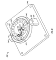
- FIG. 42 is a perspective view of a back end mechanism of the surgical instrument of FIG. 36 according to an embodiment of the present invention.
- FIG. 43 is a perspective view of a lower member in the back end mechanism of FIG. 42 according to an embodiment of the present invention.
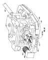
- FIGS. 44-46 are perspective views of the back end mechanism according to another embodiment of the present invention.
- FIG. 47 is a perspective view of a mechanism for securing the actuation cables in the back end of the surgical instrument of FIGS. 44-46 according to another embodiment of the present invention.
- FIG. 48 is a perspective view of a back end mechanism of the surgical instrument of FIG. 36 according to another embodiment of the present invention.
- FIGS. 49 and 50 are perspective views of a back end mechanism of the surgical instrument of FIG. 36 according to another embodiment of the present invention.
- FIG. 51 is a perspective of a PPMD wrist according to another embodiment
- FIG. 52 is an exploded view of a vertebra or disk segment in the PPMD wrist of FIG. 51 ;
- FIGS. 53 and 54 are elevational views of the PPMD wrist of FIG. 51 ;
- FIGS. 55 and 56 are perspective views illustrating the cable connections for the PPMD wrist of FIG. 51 ;
- FIGS. 57 and 58 are perspective views of a gimbaled cable actuator according to another embodiment
- FIG. 59 is a perspective view of the gimbal plate of the actuator of FIG. 55 ;
- FIGS. 60-62 are exploded perspective views of the gimbaled cable actuator of FIG. 55 ;
- FIG. 63 is another perspective view of the gimbaled cable actuator of FIG. 55 ;
- FIGS. 64-67 are perspective views of the back end according to another embodiment
- FIG. 68A is an elevational view of a straight wrist according to another embodiment
- FIG. 68C is a schematic view of a cable actuator plate according to another embodiment.
- end effector refers to an actual working distal part that is manipulable by means of the wrist member for a medical function, e.g., for effecting a predetermined treatment of a target tissue.
- some end effectors have a single working member such as a scalpel, a blade, or an electrode.
- Other end effectors have a pair or plurality of working members such as forceps, graspers, scissors, or clip appliers, for example.
- the disks or vertebrae are configured to have openings which collectively define a longitudinal lumen or space along the wrist, providing a conduit for any one of a number of alternative elements or instrumentalities associated with the operation of an end effector.
- Examples include conductors for electrically activated end effectors (e.g., electrosurgical electrodes; transducers, sensors, and the like); conduits for fluids, gases or solids (e.g., for suction, insufflation, irrigation, treatment fluids, accessory introduction, biopsy extraction and the like); mechanical elements for actuating moving end effector members (e.g., cables, flexible elements or articulated elements for operating grips, forceps, scissors); wave guides; sonic conduction elements; fiberoptic elements; and the like.
- Such a longitudinal conduit may be provided with a liner, insulator or guide element such as a elastic polymer tube; spiral wire wound tube or the like.
- the terms “surgical instrument”, “instrument”, “surgical tool”, or “tool” refer to a member having a working end which carries one or more end effectors to be introduced into a surgical site in a cavity of a patient, and is actuatable from outside the cavity to manipulate the end effector(s) for effecting a desired treatment or medical function of a target tissue in the surgical site.
- the instrument or tool typically includes a shaft carrying the end effector(s) at a distal end, and is preferably servomechanically actuated by a telesurgical system for performing functions such as holding or driving a needle, grasping a blood vessel, and dissecting tissue.
- a gastroscope style wrist has a plurality of vertebrae stacked one on top of another with alternating yaw (Y) and pitch (P) axes.
- Y yaw
- P pitch
- an example of a gastroscope-style wrist may include twelve vertebrae. Such a wrist typically bends in a relatively long arc. The vertebrae are held together and manipulated by a plurality of cables. The use of four or more cables allows the angle of one end of the wrist to be determined when moved with respect to the other end of the wrist. Accessories can be conveniently delivered through the middle opening of the wrist.
- the wrist can be articulated to move continuously to have orientation in a wide range of angles (in roll, pitch, and yaw) with good control and no singularity.
- FIGS. 1 and 2 show a typical prior art gastroscope style flexible wrist-like multi-segment member having a plurality of vertebrae or disks coupled in series in alternating yaw and pitch pivotal arrangement (YPYP . . . Y).
- FIG. 1 shows the rotation of a gastroscope-style wrist 40 having vertebrae 42 , preferably rotating at generally uniform angles between neighboring vertebrae 42 .
- the gastroscope-style wrist can take on an S shape with two arcs, as seen in FIG. 2 .
- backlash can be a problem when the angles between neighboring vertebrae vary widely along the stack.
- angles of yaw and pitch between adjacent segments may typically take a range of non-uniform, or indeterminate values during bending.
- a multi-segment wrist or flexible member may exhibit unpredictable or only partially controlled behavior in response to tendon actuation inputs. Among other things, this can reduce the bending precision, repeatability and useful strength of the flexible member.
- One way to minimize backlash and avoid the S-shape configuration is to provide springs 54 between the vertebrae 52 of the wrist 50 , as schematically illustrated in FIG. 3 .
- the springs 54 help keep the angles between the vertebrae 52 relatively uniform during rotation of the stack to minimize backlash.
- the springs 54 also stiffen the wrist 50 and stabilize the rotation to avoid the S-shape configuration.
- FIG. 4 shows an end effector in the form of a scissor or forcep mechanism 66 .
- Actuation members such as cables or pulleys for actuating the mechanism 66 may conveniently extend through the middle opening of the wrist 60 .
- the middle opening or lumen allows other items to be passed therethrough.
- yaw and pitch may be arbitrary as terms of generalized description of a multi-segment wrist or flexible member, the Y and P axes typically being generally perpendicular to a longitudinal centerline of the member and also typically generally perpendicular to each other. Note, however, that various alternative embodiments having aspects of the invention are feasible having Y and P axes which are not generally perpendicular to a centerline and/or not generally perpendicular to one another. Likewise, a simplified member may be useful while having only a single degree of freedom in bending motion (Y or P).
- a constant velocity or PPMD wrist also has a plurality of vertebrae or disks stacked one on top of another in a series of pivotally coupled engagements and manipulated by cables.
- one set of the cables extend to and terminate at the last vertebrae or distal end disk at the distal end of the wrist, while the remaining set of cables (medial cables) extend to and terminate at a middle disk.
- one of a yaw (Y) or pitch (P) coupling is repeated in two consecutive segments.
- the coupling sequence may be YPPY or PYYP, and medial segment disk (number 3 of 5) is bounded by two Y or two P couplings.
- This arrangement has the property that permits a “constant velocity” rolling motion in a “roll, pitch, yaw” type instrument distal end.
- This property “constant velocity” may simplify control algorithms for a dexterous surgical manipulation instrument, and produce smoother operation characteristics. Note that this coupling sequence is quite distinct from the alternating YPYP . . . coupling arrangement of the prior art gastroscope style wrist shown in FIGS. 1 and 2 , which includes a strictly alternating sequence of yaw and pitch axes.
- the wrist 70 has five disks 72 - 76 stacked with pitch, yaw, yaw, and pitch joints (the disk count including proximal and distal end member disks).
- the disks are annular and form a hollow center or lumen.
- Each disk has a plurality of apertures 78 for passing through actuation cables.
- sixteen cables are used.
- Eight distal cables 80 extend to the fifth disk 76 at the distal end; and eight medial cables 82 extend to the third disk 74 in the middle.
- the number of cables may change in other embodiments, although a minimum of three cables (or four in a symmetrical arrangement), more desirably six or eight cables, are used.
- each disk is about 3 mm
- the outer diameter is about 2 mm
- the apertures for passing through the cables are about 0.5 mm in diameter.
- a mechanically redundant number of cables permits the cable diameter to be smaller, and thus permits the cables to terminate at apertures positioned farther outward radially from the center line of the medial or distal disk, thus increasing the moment arm or mechanical advantage of applied cable forces.
- the resulting smaller cable diameter permits a larger unobstructed longitudinal center lumen along the centerline of the disks.
- FIG. 5 shows alternating pairs of long or distal cables 80 and short or medial cable 82 disposed around the disks.
- the cables 80 , 82 extending through the disks are parallel to a wrist central axis or neutral axis 83 extending through the centers of the disks.
- the wrist neutral axis 83 is fixed in length during bending of the wrist 70 .
- the cables 80 , 82 are straight; when the disks are rotated during bending of the wrist 70 , the cables 80 , 82 bend with the wrist neutral axis.
- the disks are configured to roll on each other in nonattached, rolling contact to maintain the contact points between adjacent disks in the center, as formed by pairs of pins 86 coupled to apertures 78 disposed on opposite sides of the disks.
- the pins 86 are configured and sized such that they provide the full range of rotation between the disks and stay coupled to the apertures 78 .
- the apertures 78 may be replaced by slots for receiving the pins 86 in other embodiments.
- the contour of pins 86 is preferably of a “gear tooth-like” profile, so as to make constant smooth contact with the perimeter 87 of its engaged aperture during disk rotation, so as to provide a smooth non-slip rolling engagement.
- FIG. 5 and 8 show the wrist 70 in a 90° pitch position (by rotation of the two pitch joints), while FIG. 6 shows the wrist 70 in a 90° yaw position (by rotation of the two yaw joints).
- FIG. 7 the wrist 70 is in an upright or straight position.
- combined pitch and yaw bending of the wrist member can be achieved by rotation of the disks both in pitch and in yaw.
- the wrist 70 is singularity free over a 180° range.
- the lumen formed by the annular disks can be used for isolation and for passing pull cables for grip.
- the force applied to the wrist 70 is limited by the strength of the cables.
- a cable tension of about 15 lb. is needed for a yaw moment of about 0.25 N-m.
- the grip mechanism needs to be able to bend sharply. Precision of the cable system depends on the friction of the cables rubbing on the apertures 78 .
- the cables 80 , 82 can be preloaded to remove backlash. Because wear is a concern, wear-resistant materials should desirably be selected for the wrist 70 and cables.
- FIGS. 9-13 show an alternative embodiment of a wrist 90 having a different coupling mechanism between the disks 92 - 96 which include apertures 98 for passing through actuation cables.
- the disks are connected by a coupling between pairs of curved protrusions 100 and slots 102 disposed on opposite sides of the disks, as best seen in the disk 94 of FIGS. 12-13 .
- the other two intermediate disks 93 , 95 are similar to the middle disk 94 .
- the curved protrusions 100 are received by the curved slots 102 which support the protrusions 100 for rotational or rolling movement relative to the slots 102 to generate, for instance, the 90° pitch of the wrist 90 as shown in FIG.
- FIG. 9 shows two distal cables 104 extending to and terminating at the distal disk 96 , and two medial cables 106 extending to and terminating at the middle disk 94 .
- the coupling between the disks 122 - 126 is formed by nonattached, rolling contact between matching gear teeth 130 disposed on opposite sides of the disks.
- the gear teeth 130 guide the disks in yaw and pitch rotations to produce, for instance, the 90° pitch of the wrist 120 as shown in FIG. 14 and the 90° yaw of the wrist 120 as shown in FIG. 15 .
- the coupling mechanism between the disks includes apertured members 150 , 152 cooperating with one another to permit insertion of a fastener through the apertures to form a hinge mechanism.
- the hinge mechanisms disposed on opposite sides of the disks guide the disks in pitch and yaw rotations to produce, for instance, the 90° pitch of the wrist 140 as seen in FIG. 16 .
- the example shown in FIG. 16 is not a “constant velocity” YPPY arrangement, but may alternatively be so configured.
- FIGS. 17-24 show yet another embodiment of the wrist 160 having a different coupling mechanism between the disks 162 - 166 .
- the first or proximal disk 162 includes a pair of pitch protrusions 170 disposed on opposite sides about 180° apart.
- the second disk 163 includes a pair of matching pitch protrusions 172 coupled with the pair of pitch protrusions 170 on one side, and on the other side a pair of yaw protrusions 174 disposed about 90° offset from the pitch protrusions 172 .
- the third or middle disk 164 includes a pair of matching yaw protrusions 176 coupled with the pair of yaw protrusions 174 on one side, and on the other side a pair of yaw protrusions 178 aligned with the pair of yaw protrusions 174 .
- the fourth disk 165 includes a pair of matching yaw protrusions 180 coupled with the pair of yaw protrusions 178 on one side, and on the other side a pair of pitch protrusions 182 disposed about 90° offset from the yaw protrusions 180 .
- the fifth or distal disk 166 includes a pair of matching pitch protrusions 184 coupled with the pitch protrusions 182 of the fourth disk 165 .
- the protrusions 172 and 176 having curved, convex rolling surfaces that make nonattached, rolling contact with each other to guide the disks in pitch or yaw rotations to produce, for instance, the 90° pitch of the wrist 160 as seen in FIGS. 18 and 19 and the 90° yaw of the wrist 160 as seen in FIGS. 20 and 21 .
- the coupling between the protrusions is each formed by a pin 190 connected to a slot 192 .
- FIGS. 22-24 illustrate the wrist 160 manipulated by actuation cables to achieve a straight position, a 90° pitch position, and a 90° yaw position, respectively.
- FIG. 25 illustrates the rolling contact between the curved rolling surfaces of protrusions 170 , 172 for disks 162 , 163 , which maintain contact at a rolling contact point 200 .
- the rolling action implies two virtual pivot points 202 , 204 on the two disks 162 , 163 , respectively.
- the relative rotation between the disks 162 , 163 is achieved by pulling cables 212 , 214 , 216 , 218 .
- Each pair of cables ( 212 , 218 ) and ( 214 , 216 ) are equidistant from the center line 220 that passes through the contact point 200 and the virtual pivot points 202 , 204 .
- the disk 162 has cable exit points 222 for the cables, and the disk 163 has cable exit points 224 for the cables.
- the cable exit points 222 are coplanar with the virtual pivot point 202 of the disk 162
- the cable exit points 224 are coplanar with the virtual pivot point 204 of the disk 164 . In this way, upon rotation of the disks 162 , 163 , each pair of cables ( 212 ′, 218 ′) and ( 214 ′, 216 ′) are kept equidistant from the center line 220 .
- the non-attached, rolling engagement contour arrangement shown in FIG. 25 may be referred to as a “cable balancing pivotal mechanism.”
- This “cable balancing” property facilitates coupling of pairs of cables with minimal backlash. Note that the example of FIGS. 17-24 has this “cable balancing” property, although due to the size of these figures, the engagement rolling contours are shown at a small scale.
- the instrument cable actuator(s) may employ a cable tension regulation device to take up cable slack or backlash.
- the above embodiments show five disks, but the number of disks may be increased to seven, nine, etc.
- the range of rotation increases from 180° to 270°.
- typically 1 ⁇ 3 of the cables terminate at disk 3; 1 ⁇ 3 terminate at disk 5; and 1 ⁇ 3 terminate at disk 7 (most distal).
- FIG. 26 shows an exemplary pivoted plate cable actuator mechanism 240 having aspects of the invention, for manipulating the cables, for instance, in the PPMD wrist 160 shown in FIGS. 17-21 .
- the actuator 240 includes a base 242 having a pair of gimbal ring supports 244 with pivots 245 for supporting a gimbal ring 246 for rotation, for example, in pitch.
- the ring 246 includes pivots 247 for supporting a rocker or actuator plate 250 in rotation, for example, in yaw.
- the actuator plate 250 includes sixteen holes 252 for passing through sixteen cables for manipulating the wrist 160 (from the proximal disk 162 , eight distal cables extend to the distal disk 166 and eight medial cables extend to the middle disk 164 ).
- the actuator plate 250 includes a central aperture 256 having a plurality of grooves for receiving the cables. There are eight small radius grooves 258 and eight large radius grooves 260 distributed in pairs around the central aperture 256 .
- the small radius grooves 258 receive medial cables that extend to the middle disk 164
- the large radius grooves 260 receive distal cables that extend to the distal disk 166 .
- the large radius for grooves 260 is equal to about twice the small radius for grooves 258 .
- the cables are led to the rim of the central aperture 256 through the grooves 258 , 260 which restrain half of the cables to a small radius of motion and half of the cables to a large radius of motion, so that the medial cables to the medial disk 164 move only half as far as the distal cables to the distal disk 166 , for a given gimbal motion.
- the dual radius groove arrangement facilitates such motion and control of the cables when the actuator plate 250 is rotated in the gimbaled cable actuator 240 .
- a pair of set screws 266 are desirably provided to fix the cable attachment after pretensioning.
- the gimbaled cable actuator 240 acts as a master for manipulating and controlling movement of the slave PPMD wrist 160 .
- Various kinds of conventional actuator may be coupled to actuator plate assembly to controllably tilt the plate in two degrees of freedom to actuate to cables.
- FIGS. 27-35 illustrate another embodiment of a gimbaled cable actuator 300 for manipulating the cables to control movement of the PPMD wrist, in which an articulated parallel strut/ball joint assembly is employed to provide a “gimbaled” support for actuator plate 302 (i.e., the plate is supported so as to permit plate tilting in two DOF).
- the actuator 300 includes a rocker or actuator plate 302 mounted in a gimbal configuration.
- the actuator plate 302 is moved by a first actuator link 304 and a second actuator link 306 to produce pitch and yaw rotations.
- the actuator links 304 , 306 are rotatably coupled to a mounting member 308 disposed around the actuator plate 302 . As best seen in FIG.
- ball ends 310 are used for coupling the actuator links 304 , 306 with the mounting member 308 to form ball-in-socket joints in the specific embodiment shown, but other suitable rotational connections may be used in alternate embodiments.
- the actuator links 304 , 306 are driven to move generally longitudinally by first and second follower gear quadrants 314 , 316 , respectively, which are rotatably coupled with the actuator links 304 , 306 via pivot joints 318 , 320 , as shown in FIGS. 27 and 28 .
- the gear quadrants 314 , 316 are rotated by first and second drive gears 324 , 326 , respectively, which are in turn actuated by drive spools 334 , 336 , as best seen in FIGS. 34 and 35 .
- the actuator plate 302 is coupled to a parallel linkage 340 as illustrated in FIGS. 30-33 .
- the parallel linkage 340 includes a pair of parallel links 342 coupled to a pair of parallel rings 344 which form a parallelogram in a plane during movement of the parallel linkage 340 .
- the pair of parallel links 342 are rotatably connected to the pair of parallel rings 344 , which are in turn rotatably connected to a parallel linkage housing 346 via pivots 348 to rotate in pitch.
- the pair of parallel links 342 may be coupled to the actuator plate 302 via ball-in-socket joints 349 , as best seen in FIG. 32 , although other suitable coupling mechanisms may be used in alternate embodiments.
- FIGS. 27 and 29 show the actuator plate 302 of the gimbaled cable actuator 300 in pitch rotation with both actuator links 304 , 306 moving together so that the actuator plate 302 is constrained by the parallel linkage 340 to move in pitch rotation.
- the first and second actuator links 304 , 306 move in opposite directions to produce a yaw rotation of the actuator plate 302 .
- Mixed pitch and yaw rotations result from adjusting the mixed movement of the actuator links 304 , 306 .
- the actuator plate 302 includes eight small radius apertures 360 for receiving medial cables and eight large radius apertures 362 for receiving distal cables.
- FIG. 32 shows a medial cable 364 for illustrative purposes.
- the medial and distal actuation cables extend through the hollow center of the parallel linkage housing 346 and the hollow center of the shaft 370 ( FIGS. 27 and 28 ), for instance, to the middle and distal disks 164 , 166 of the PPMD wrist 160 of FIGS. 17-21 .
- FIG. 34 shows the gimbaled cable actuator 300 mounted on a lower housing member 380 .
- FIG. 35 shows an upper housing member 382 mounted on the lower housing member 380 .
- the upper housing member 382 includes pivots 384 for rotatably mounting the gear quadrants 314 , 316 .
- a cover plate 390 may be mounted over the actuator plate 302 by fasteners 392 , as seen in FIGS. 27, 28, 31, 33, and 34 .
- the most distal disk may serve as a mounting base for various kinds of single-element and multi-element end effectors, such as scalpels, forceps, scissors, cautery tools, retractors, and the like.
- the central lumen internal to the disks may serve as a conduit for end-effector actuator elements (e.g., end effector actuator cables), and may also house fluid conduits (e.g., irrigation or suction) or electrical conductors.
- gimbal ring support assembly 240 is shown in FIG. 26 for actuator plate 250
- an articulated gimbal-like structure 300 is shown in FIGS. 27-35 for actuator plate 302
- alternative embodiments of the pivoted-plate cable actuator mechanism having aspects of the invention may have different structures and arrangements for supporting and controllably moving the actuator plate 250 .
- the plate may be supported and moved by various types of mechanisms and articulated linkages to permit at least tilting motion in two DOF, for example a Stewart platform and the like.
- the plate assembly may be controllably actuated by a variety of alternative drive mechanisms, such as motor-driven linkages, hydraulic actuators; electromechanical actuators, linear motors, magnetically coupled drives and the like.
- a back end or instrument manipulating mechanism 410 is located at an opposed end of the shaft 402 , and is arranged releasably to couple the instrument 400 to a robotic arm or system.
- the robotic arm is used to manipulate the back end mechanism 410 to operate the wrist-like mechanism 404 and the end effector 406 .
- Examples of such robotic systems are found in various related applications as listed above, such as PCT International Application No. PCT/US98/19508, entitled “Robotic Apparatus”, filed on Sep. 18, 1998, and published as WO99/50721; and U.S. patent application Ser. No. 09/398,958, entitled “Surgical Tools for Use in Minimally Invasive Telesurgical Applications”, filed on Sep. 17, 1999.
- the shaft 402 is rotatably coupled to the back end mechanism 410 to enable angular displacement of the shaft 402 relative to the back end mechanism 410 as indicated by arrows H.
- the jaws 422 , 424 close in rotation around the pivot pins 426 , 428 .
- the sliding movement of the slider pins 432 , 434 is generated by their contact with the opening actuator 436 as it moves relative to the closing actuator 438 .
- the opening actuator 436 acts as a cam on the slider pins 432 , 434 .
- the closing of the jaws 422 , 424 is produced by pulling the closing actuator 438 back toward the shaft 402 relative to the opening actuator 436 using a closing actuator cable 448 , as shown in FIG. 39A .
- the opening of the jaws 422 , 424 is produced by pulling the opening actuator 436 back toward the shaft 402 relative to the closing actuator 438 using an opening actuator cable 446 , as shown in FIG. 39B .
- the opening actuator cable 446 is typically crimped into the hollow tail of the opening actuator 436
- the closing actuator cable 448 is typically crimped into the hollow tail of the closing actuator 438 .
- the opening actuator cable 446 and the closing actuator cable 448 are moved in conjunction with one another, so that the opening actuator 436 and the closing actuator 438 move simultaneously at an equal rate, but in opposite directions.
- the actuation cables 446 , 448 are manipulated at the back end mechanism 410 , as described in more detail below.
- the closing actuator 438 is a slotted member and the closing actuator cable 446 may be referred to as the slotted member cable.
- the opening actuator 436 is a slider pin actuator and the opening actuator cable 448 may be referred to as the slider pin actuator cable.
- FIG. 40 shows one distal cable 452 and one medial cable 454 for illustrative purposes.
- Each cable ( 452 , 454 ) extends through adjacent sets of apertures with free ends extending proximally through the tool shaft 402 , and makes two passes through the length of the wrist 404 .
- actuation cables 446 , 448 and the wrist control cables such as 452 , 454 pass through the lumen formed by the annular disks 412 - 416 back through the shaft 402 to the back end mechanism 410 , where these cables are manipulated.
- a conduit 450 is provided in the lumen formed by the annular disks 412 - 416 (see FIG. 39 ) to minimize or reduce cable snagging or the like.
- the conduit 450 is formed by a coil spring connected between the proximal disk 412 and the distal disk 416 . The coil spring bends with the disks 412 - 416 without interfering with the movement of the disks 412 - 416 .
- the grip support 420 may be fastened to the wrist 404 using any suitable method.
- the grip support 420 is held tightly to the wrist 404 by support cables 462 , 464 , as illustrated in FIGS. 38 and 38A .
- Each support cable extends through a pair of adjacent holes in the grip support 420 toward the wrist 404 .
- the support cables 462 , 464 also pass through the lumen formed by the annular disks 412 - 416 back through the shaft 402 to the back end mechanism 410 , where they are secured.
- the wrist 404 has a wrist central axis or neutral axis 470 that is fixed in length during bending of the wrist 404 .
- the various cables vary in length during bending of the wrist 404 as they take on cable paths that do not coincide with the neutral axis, such as the cable path 472 shown. Constraining the cables to bend substantially along the neutral axis 470 (e.g., by squeezing down the space in the wrist 404 ) reduces the variation in cable lengths, but will tend to introduce excessive wear problems. In some embodiments, the change in cable lengths will be accounted for in the back end mechanism 410 , as described below.
- the support cables 462 , 464 (see FIGS. 38 and 38A ) used to hold the grip support 420 to the wrist 404 extend through a central tube after passing through the shaft 402 .
- the support cables 462 , 464 are clamped to a lower arm 480 and lower clamp block 482 which are screwed tight.
- the lower arm 480 includes a pivot end 486 and a spring attachment end 488 .
- the pivot end 486 is rotatably mounted to the back end housing or structure 490 , as shown in FIG. 42 .
- the spring attachment end 488 is connected to a spring 492 which is fixed to the back end housing 490 .
- the spring 492 biases the lower arm 480 to apply tension to the support cables 462 , 464 to hold the grip support 420 tightly to the wrist 404 .
- FIG. 43 shows another way to secure the support cables 462 , 464 by using four recesses or slots 484 in the lower arm 480 instead of the clamp block 482 .
- a sleeve is crimped onto each of the ends of the support cables 462 , 464 , and the sleeves are tucked into the recesses or slots 484 . This is done by pushing the lower arm 480 inward against the spring force, and slipping the sleeved cables into their slots.
- FIG. 44 shows an additional mechanism that allows the lengths of the actuation cables 446 , 448 (see FIG. 39 ) to change without affecting the position of the grip jaws 422 , 424 .
- the actuation cables 446 , 448 extending through the shaft 402 are clamped to a grip actuation pivoting shaft 500 at opposite sides of the actuation cable clamping member 502 with respect to the pivoting shaft 500 .
- the clamping member 502 rotates with the grip actuation pivoting shaft 500 so as to pull one actuation cable while simultaneously releasing the other to operate the jaws 422 , 424 of the end effector 406 .
- the cable securing member 502 ′ includes a pair of oppositely disposed recesses or slots 504 .
- a sleeve is crimped onto each of the ends of the actuation cables 446 , 448 , and the sleeves are tucked into the recesses or slots 504 . This is done by pushing the upper arm 530 inward against the spring force, and slipping the sleeved cables into their slots.
- the grip actuation pivot shaft 500 is controlled by a pair of control cables 506 , 508 that are connected to the motor input shaft 510 .
- the two control cables 506 , 508 are clamped to the grip actuation pivot shaft 500 by two hub clamps 512 , 514 , respectively. From the hub clamps 512 , 514 , the control cables 506 , 508 travel to two helical gear reduction idler pulleys 516 , 518 , and then to the motor input shaft 510 , where they are secured by two additional hub clamps 522 , 524 .
- the two control cables 506 , 508 are oppositely wound to provide the proper torque transfer in both clockwise and counterclockwise directions. Rotation of the motor input shaft 510 twists the grip actuation pivot shaft 500 via the control cables 506 , 508 , which in turn pulls one actuation cable while simultaneously releasing the other, thereby actuating the jaws 422 , 424 of the end effector 406 .
- the grip actuation pivot shaft 500 and the pair of helical gear reduction idler pulleys 516 , 518 are pivotally supported by a link box 520 .
- the link box 520 is connected to a link beam 522 , which is pivotally supported along the axis of the motor input shaft 510 to allow the grip actuation pivot shaft 500 to move back and forth to account for change in cable length due to bending of the wrist 404 , without changing the relative position of the two actuation cables 446 , 448 that control the grip jaws 422 , 424 .
- This feature decouples the control of the grip jaws 422 , 424 from the bending of the wrist 404 .
- FIGS. 45 and 46 show the addition of an upper arm 530 which is similar to the lower arm 480 .
- the upper arm 530 also has a pivot end 536 and a spring attachment end 538 .
- the pivot end 536 is rotatably mounted to the back end housing 490 along the same pivot axis as the pivot end 486 of the lower arm 480 .
- the upper arm 530 is connected to the grip actuation pivot shaft 500 .
- the spring attachment end 538 is connected to a spring 542 which is fixed to the back end housing 490 .
- the spring 542 biases the upper arm 530 to apply a pretension to the actuation cables 446 , 448 .
- the springs 492 , 542 are not shown in FIG. 46 for simplicity and clarity.
- the configuration of the back end mechanism 410 facilitates relatively easy replacement of the actuators 436 , 438 and actuation cables 446 , 448 , as well as the working members or jaws 422 , 424 .
- the cables can be released from the back end mechanism 410 with relative ease, particularly when the cables are secured to recesses by crimped sleeves (see FIGS. 43, 47 ).
- the wrist cables e.g., the distal cable 452 and medial cable 454 in FIG. 40
- the wrist cables are clamped to the actuator plate 302 with a cover plate 390 (see FIGS. 27-35 ).
- the wrist cables are fastened to a smaller plate (e.g., by clamping), and the smaller plate is fed from the instrument from the front 550 of the back end housing 490 and affixed to the actuator plate 302 .
- the actuator plate 302 may be repositioned to the front 550 of the back end housing 490 to eliminate the need to thread the smaller plate through the length of the shaft 402 .
- FIGS. 49 and 50 show another back end mechanism 410 B illustrating another way of securing the cables.
- the support cables 462 , 464 (see FIGS. 38 and 38A ) are clamped to the arm 560 by a clamping block 562 .
- the arm 560 has a pivot end 564 and a spring attachment end 566 .
- the pivot end 564 is rotatably mounted to the back end housing or structure 490 .
- the spring attachment end 566 is connected to one or more springs 570 which are fixed to the back end housing 490 .
- the springs 570 bias the arm 560 to apply tension to the support cables 462 , 464 to hold the grip support 420 tightly to the wrist 404 .
- the actuation cables 446 , 448 extend around pulleys 580 connected to the arm 560 , and terminate at a pair of hub clamps 582 , 584 provided along the motor input shaft 590 .
- This relatively simple arrangement achieves the accommodation of cable length changes and pretensioning of the cables.
- the support cables 462 , 464 are tensioned by the springs 570 .
- the actuation cables 446 , 448 are tensioned by applying a torque to the hub clamps 582 , 584 .
- the replacement of the end effector 406 and wrist 404 will be more difficult than some of the embodiments described above.
- FIGS. 51-67 illustrate another PPMD wrist tool that is designed to have certain components that are more compact or easier to manufacture or assemble.
- the PPMD wrist 600 connected between a tool shaft 602 and an end effector 604 .
- the wrist 600 includes eight nested disk segments 611 - 618 that are preferably identical, which improves manufacturing efficiency and cost-effectiveness.
- An individual disk segment 610 is seen in FIG. 52 .
- Four struts 620 are provided, each of which is used to connect a pair of disk segments together.
- An individual strut 620 is shown in FIG. 52 .
- the disk segment 610 includes a mating side having a plurality of mating extensions 622 extending in the axial direction (four mating extensions spaced around the circumference in a specific embodiment), and a pivoting side having a gear tooth 624 and a gear slot 626 .
- the gear tooth 624 and gear slot 626 are disposed on opposite sides relative to a center opening 628 . Twelve apertures 630 are distributed around the circumference of the disk segment 610 to receive cables for wrist actuation, as described in more detail below.
- the disk segment 610 further includes a pair of radial grooves or slots 632 disposed on opposite sides relative to the center opening 628 . In the specific embodiment shown, the radial grooves 632 are aligned with the gear tooth 624 and gear slot 626 .
- the strut 620 includes a ring 634 , a pair of upper radial plugs or projections 636 disposed on opposite sides of the ring 634 , and a pair of lower radial plugs or projections 638 disposed on opposite sides of the ring 634 .
- the upper radial projections 636 and lower radial projections 638 are aligned with each other.
- the pair of lower radial projections 638 are inserted by sliding into the pair of radial grooves 632 of a lower disk segment.
- An upper disk segment is oriented in an opposite direction from the lower disk segment, so that the pivoting side with the gear tooth 624 , gear slot 626 , and radial grooves 632 faces toward the strut 620 .
- the pair of upper radial projections 638 of the strut 620 are inserted by sliding into the pair of radial grooves 632 of the upper disk segment.
- the radial projections and radial grooves are circular cylindrical in shape to facilitate pivoting between the disk segments.
- the gear tooth 624 of the lower disk segment is aligned with the gear slot 626 of the upper disk segment to pivot relative thereto, while the gear tooth 624 of the upper disk segment is aligned with the gear slot 626 of the lower disk segment to pivot relative thereto. This is best seen in FIG. 51 .
- the movement between the gear tooth 624 and gear slot 626 is made by another nonattached contact.
- the proximal or first disk segment 611 is connected to the end of the tool shaft 602 by the mating extensions 622 of the disk segment 611 and mating extensions 603 of the shaft 602 .
- the second disk segment 612 is oriented opposite from the first disk segment 611 , and is coupled to the first segment 611 by a strut 620 .
- the gear tooth 624 of the second disk segment 612 is engaged with the gear slot 626 of the first disk segment 611
- the gear tooth 624 of the first disk segment 611 is engaged with the gear slot 626 of the second disk segment 612 .
- the third disk segment 613 is oriented opposite from the second disk segment 612 , with their mating sides facing one another and the mating extensions 622 mating with each other.
- the second disk segment 612 and the third disk segment 613 forms a whole disk.
- the fourth disk segment 614 and fifth disk segment 615 form a whole disk
- the sixth disk segment 616 and the seventh disk segment 617 form another whole disk.
- the other three struts 620 are used to rotatably connect, respectively, third and fourth disk segments 613 , 614 ; fifth and sixth disk segments 615 , 616 ; and seventh and eighth disk segments 617 , 618 .
- the eighth or distal disk segment 618 is connected to the end effector 604 by the mating extensions 622 of the disk segment 618 and the mating extensions 605 of the end effector 604 .
- the rotational coupling between the first disk segment 611 and second disk segment 612 provides pitch rotation 640 of typically about 45°
- the rotational coupling between the seventh disk segment 617 and eighth disk segment 618 provides additional pitch rotation 640 of typically about 45° for a total pitch of about 90°.
- the four disk segments in the middle are circumferentially offset by 90° to provide yaw rotation.
- the rotational coupling between the third disk segment 613 and fourth disk segment 614 provides yaw rotation 642 of typically about 45°
- the rotational coupling between the fifth disk segment 615 and sixth disk segment 161 provides additional yaw rotation 642 of typically about 45° for a total yaw of about 90°.
- different orientations of the disk segments may be formed in other embodiments to achieve different combinations of pitch and yaw rotation, and additional disk segments may be included to allow the wrist to rotate in pitch and yaw by greater than 90°.
- FIGS. 57-63 show a gimbal mechanism 700 in the back end of the tool.
- the gimbal mechanism 700 is more compact than the gimbal mechanism comprising the gimbal plate 302 and parallel linkage mechanism 340 of FIGS. 35-40 .
- the gimbal mechanism 700 includes another gimbal member or ring 702 that is mounted to rotate around an axis 704 .
- a gimbal plate or actuator plate 706 is mounted to the outer ring 700 to rotate around an orthogonal axis 708 .
- a lock plate 710 is placed over the gimbal plate 706 . As seen in FIG.
- the cables 650 from the wrist 600 are inserted through twelve cable holes 714 , 716 of the gimbal plate 706 , and pulled substantially straight back along arrow 716 toward the proximal end of the back end of the tool.
- the gimbal plate 706 includes six large radius apertures 714 for receiving distal cables 650 A and six small radius apertures 716 for receiving medial cables 650 B.
- the gimbal plate 706 has a first actuator connection 718 and a second actuator connection 719 for connecting to actuator links, as described below.
- FIGS. 60 and 61 show the gimbal plate 706 and the lock plate 710 prior to assembly.
- the lock plate 710 is used to lock the cables 650 A, 650 B in place by moving wedges against the cables 650 .
- the lock plate has three outward wedges 720 with radially outward facing wedge surfaces and three inward wedges 722 with radially inward facing wedge surface, which are alternately arranged around the lock plate 710 .
- the gimbal plate 706 has corresponding loose or movable wedges that mate with the fixed wedges 720 , 722 of the lock plate 710 . As best seen in FIG.
- the gimbal plate 706 includes three movable inward wedges 730 with radially inward facing wedge surfaces and curved outward surfaces 731 , and three movable outward wedges 732 with radially outward facing wedge surfaces and curved inward surface 733 . These movable wedges 730 , 732 are alternately arranged and inserted into slots provided circumferentially around the gimbal plate 706 .
- the lock plate 710 is assembled with the gimbal plate 706 after the cables 650 are inserted through the cable holes 714 , 716 of the gimbal plate 706 .
- the three outward wedges 720 of the lock plate 720 mate with the three movable inward wedges 730 in the slots of the gimbal plate 706 to push the movable inward wedges 730 radially outward against the six distal cables 650 A extending through the six large radius apertures 714 , which are captured between the curved outward surfaces 731 of the wedges 730 and the gimbal plate wall.
- the three inward wedges 722 of the lock plate 720 mate with the three movable outward wedges 732 in the slots of the gimbal plate 706 to push the movable outward wedges 732 radially inward against the six medial cables 650 B extending through the six small radius apertures 716 , which are captured between the curved inward surfaces 733 of the wedges 732 and the gimbal plate wall.
- the lock plate 710 is attached to the gimbal plate 706 using fasteners 738 such as threaded bolts or the like, which may be inserted from the gimbal plate 706 into the lock plate 710 , or vice versa.
- fasteners 738 such as threaded bolts or the like
- the gimbaled cable actuator 800 incorporating the gimbal mechanism 700 as illustrated in the back end 801 FIGS. 64-67 is similar to the gimbaled cable actuator 300 of FIGS. 32-40 , but are rearranged and reconfigured to be more compact and efficient.
- the gimbaled cable actuator 800 is mounted on a lower housing member of the back end and the upper housing member is removed to show the internal details.
- the gimbal plate 706 of the gimbal mechanism 700 is moved by a first actuator link 804 rotatably coupled to the first actuator connection 718 of the gimbal plate 706 , and a second actuator link 806 rotatably coupled to the second actuator connection 719 of the gimbal plate 706 , to produce pitch and yaw rotations.
- the rotatable coupling at the first actuator connection 718 and the second actuator connection 719 may be ball-in-socket connections.
- the actuator links 804 , 806 are driven to move generally longitudinally by first and second follower gear quadrants 814 , 816 , respectively, which are rotatably coupled with the actuator links 804 , 806 via pivot joints.
- the gear quadrants 814 , 816 are rotated by first and second drive gears 824 , 826 , respectively, which are in turn actuated by drive spools 834 , 836 .
- the gear quadrants 814 , 816 rotate around a common pivot axis 838 .
- the arrangement is more compact than that of FIGS. 32-40 .
- the first and second actuator links 804 , 806 move in opposite directions to produce a yaw rotation of the gimbal plate 706 , and move together in the same direction to produce a pitch rotation of the gimbal plate 706 .
- Mixed pitch and yaw rotations result from adjusting the mixed movement of the actuator links 804 , 806 .
- Helical drive gear 840 and follower gear 842 are used to produce row rotation for improved efficiency and cost-effectiveness.
- FIGS. 68A, 68B, and 68C illustrate schematically a PPMD wrist embodiment and corresponding actuator plate having aspects of the invention, wherein the wrist includes more than five segments or disks, and has more than one medial disk with cable termination.
- the PPMD wrist shown in this example has 7 disks (numbered 1-7 from proximal shaft end disk to distal end effector support disk), separated by 6 pivotal couplings in a P,YY,PP,Y configuration.
- Three exemplary cable paths are shown, for cable sets c1, c2 and c3, which terminate at medial disks 3, 5 and 7 respectively.
- FIG. 68A shows the wrist in a straight conformation
- FIG. 68B shows the wrist in a yaw-deflected or bent conformation.
- the wrist may similarly be deflected in pitch (into or out of page), or a combination of these. Except for the number of segments and cable sets, the wrist shown is generally similar to the embodiment shown in FIGS. 17-24 .
- the wrist shown is of the type having at least a pair of generally parallel adjacent axes (e.g., . . . YPPY . . . or . . . PYYP . . . ), but may alternatively be configured with a PY,PY,PY alternating perpendicular axes arrangement. Still further alternative embodiments may have combination configurations of inter-disk couplings, such as PYYP,YP and the like.
- the wrist illustrated has a constant segment length and sequentially repeated pivot axes orientations. In more general alternative exemplary embodiments, the “Y” and “P” axes need not be substantially perpendicular to each other and need not be substantially perpendicular to the centerline, and the sequential segments need not be of a constant length.
- FIG. 68C shows schematically the cable actuator plate layout, including cable set connections at r1, r2 and r3, corresponding to cable sets c1, c2 and c3 respectively. Four connections are shown per cable set, but the number may be 3, and may be greater than 4.
Abstract
Description
Claims (15)
Priority Applications (3)
| Application Number | Priority Date | Filing Date | Title |
|---|---|---|---|
| US14/536,899 US9717486B2 (en) | 2001-06-29 | 2014-11-10 | Apparatus for pitch and yaw rotation |
| US15/624,344 US10105128B2 (en) | 2001-06-29 | 2017-06-15 | Apparatus for pitch and yaw rotation |
| US16/162,652 US11051794B2 (en) | 2001-06-29 | 2018-10-17 | Apparatus for pitch and yaw rotation |
Applications Claiming Priority (7)
| Application Number | Priority Date | Filing Date | Title |
|---|---|---|---|
| US30196701P | 2001-06-29 | 2001-06-29 | |
| US32770201P | 2001-10-05 | 2001-10-05 | |
| US10/187,248 US6817974B2 (en) | 2001-06-29 | 2002-06-28 | Surgical tool having positively positionable tendon-actuated multi-disk wrist joint |
| US10/980,119 US7736356B2 (en) | 2001-06-29 | 2004-11-01 | Surgical tool having positively positionable tendon-actuated multi-disk wrist joint |
| US12/782,833 US8142421B2 (en) | 2001-06-29 | 2010-05-19 | Surgical tool having positively positionable tendon-actuated multi-disk wrist joint |
| US13/414,445 US8911428B2 (en) | 2001-06-29 | 2012-03-07 | Apparatus for pitch and yaw rotation |
| US14/536,899 US9717486B2 (en) | 2001-06-29 | 2014-11-10 | Apparatus for pitch and yaw rotation |
Related Parent Applications (1)
| Application Number | Title | Priority Date | Filing Date |
|---|---|---|---|
| US13/414,445 Continuation US8911428B2 (en) | 2001-06-29 | 2012-03-07 | Apparatus for pitch and yaw rotation |
Related Child Applications (1)
| Application Number | Title | Priority Date | Filing Date |
|---|---|---|---|
| US15/624,344 Continuation US10105128B2 (en) | 2001-06-29 | 2017-06-15 | Apparatus for pitch and yaw rotation |
Publications (2)
| Publication Number | Publication Date |
|---|---|
| US20150066002A1 US20150066002A1 (en) | 2015-03-05 |
| US9717486B2 true US9717486B2 (en) | 2017-08-01 |
Family
ID=27392222
Family Applications (7)
| Application Number | Title | Priority Date | Filing Date |
|---|---|---|---|
| US10/187,248 Expired - Lifetime US6817974B2 (en) | 2001-06-29 | 2002-06-28 | Surgical tool having positively positionable tendon-actuated multi-disk wrist joint |
| US10/980,119 Active 2025-09-03 US7736356B2 (en) | 2001-06-29 | 2004-11-01 | Surgical tool having positively positionable tendon-actuated multi-disk wrist joint |
| US12/782,833 Expired - Lifetime US8142421B2 (en) | 2001-06-29 | 2010-05-19 | Surgical tool having positively positionable tendon-actuated multi-disk wrist joint |
| US13/414,445 Expired - Lifetime US8911428B2 (en) | 2001-06-29 | 2012-03-07 | Apparatus for pitch and yaw rotation |
| US14/536,899 Expired - Lifetime US9717486B2 (en) | 2001-06-29 | 2014-11-10 | Apparatus for pitch and yaw rotation |
| US15/624,344 Expired - Lifetime US10105128B2 (en) | 2001-06-29 | 2017-06-15 | Apparatus for pitch and yaw rotation |
| US16/162,652 Expired - Lifetime US11051794B2 (en) | 2001-06-29 | 2018-10-17 | Apparatus for pitch and yaw rotation |
Family Applications Before (4)
| Application Number | Title | Priority Date | Filing Date |
|---|---|---|---|
| US10/187,248 Expired - Lifetime US6817974B2 (en) | 2001-06-29 | 2002-06-28 | Surgical tool having positively positionable tendon-actuated multi-disk wrist joint |
| US10/980,119 Active 2025-09-03 US7736356B2 (en) | 2001-06-29 | 2004-11-01 | Surgical tool having positively positionable tendon-actuated multi-disk wrist joint |
| US12/782,833 Expired - Lifetime US8142421B2 (en) | 2001-06-29 | 2010-05-19 | Surgical tool having positively positionable tendon-actuated multi-disk wrist joint |
| US13/414,445 Expired - Lifetime US8911428B2 (en) | 2001-06-29 | 2012-03-07 | Apparatus for pitch and yaw rotation |
Family Applications After (2)
| Application Number | Title | Priority Date | Filing Date |
|---|---|---|---|
| US15/624,344 Expired - Lifetime US10105128B2 (en) | 2001-06-29 | 2017-06-15 | Apparatus for pitch and yaw rotation |
| US16/162,652 Expired - Lifetime US11051794B2 (en) | 2001-06-29 | 2018-10-17 | Apparatus for pitch and yaw rotation |
Country Status (5)
| Country | Link |
|---|---|
| US (7) | US6817974B2 (en) |
| EP (7) | EP2659854B1 (en) |
| JP (8) | JP4332031B2 (en) |
| AU (1) | AU2002318461A1 (en) |
| WO (1) | WO2003001986A2 (en) |
Cited By (5)
| Publication number | Priority date | Publication date | Assignee | Title |
|---|---|---|---|---|
| US10105128B2 (en) | 2001-06-29 | 2018-10-23 | Intuitive Surgical Operations, Inc. | Apparatus for pitch and yaw rotation |
| US10506920B2 (en) | 2001-06-29 | 2019-12-17 | Intuitive Surgical Operations, Inc. | Articulate and swappable endoscope for a surgical robot |
| US10524868B2 (en) | 2002-12-06 | 2020-01-07 | Intuitive Surgical Operations, Inc. | Flexible wrist for surgical tool |
| US11066152B2 (en) * | 2018-05-25 | 2021-07-20 | The Boeing Company | Slotted entry gimbal |
| US11576738B2 (en) | 2018-10-08 | 2023-02-14 | Auris Health, Inc. | Systems and instruments for tissue sealing |
Families Citing this family (1419)
| Publication number | Priority date | Publication date | Assignee | Title |
|---|---|---|---|---|
| US7789875B2 (en) | 1998-02-24 | 2010-09-07 | Hansen Medical, Inc. | Surgical instruments |
| US6949106B2 (en) | 1998-02-24 | 2005-09-27 | Endovia Medical, Inc. | Surgical instrument |
| US8303576B2 (en) | 1998-02-24 | 2012-11-06 | Hansen Medical, Inc. | Interchangeable surgical instrument |
| US7758569B2 (en) | 1998-02-24 | 2010-07-20 | Hansen Medical, Inc. | Interchangeable surgical instrument |
| US7713190B2 (en) | 1998-02-24 | 2010-05-11 | Hansen Medical, Inc. | Flexible instrument |
| US7901399B2 (en) | 1998-02-24 | 2011-03-08 | Hansen Medical, Inc. | Interchangeable surgical instrument |
| US7775972B2 (en) | 1998-02-24 | 2010-08-17 | Hansen Medical, Inc. | Flexible instrument |
| US8414598B2 (en) | 1998-02-24 | 2013-04-09 | Hansen Medical, Inc. | Flexible instrument |
| US20020087148A1 (en) * | 1998-02-24 | 2002-07-04 | Brock David L. | Flexible instrument |
| US7344547B2 (en) | 1998-09-15 | 2008-03-18 | Phavel Systems, Inc. | Laparoscopic instruments and trocar systems and related surgical method |
| EP1224918A3 (en) | 1999-05-10 | 2002-12-18 | endoVia Medical Inc. | Surgical instrument |
| US7637905B2 (en) | 2003-01-15 | 2009-12-29 | Usgi Medical, Inc. | Endoluminal tool deployment system |
| US8574243B2 (en) * | 1999-06-25 | 2013-11-05 | Usgi Medical, Inc. | Apparatus and methods for forming and securing gastrointestinal tissue folds |
| US6626899B2 (en) | 1999-06-25 | 2003-09-30 | Nidus Medical, Llc | Apparatus and methods for treating tissue |
| US8768516B2 (en) | 2009-06-30 | 2014-07-01 | Intuitive Surgical Operations, Inc. | Control of medical robotic system manipulator about kinematic singularities |
| JP2004504095A (en) | 2000-07-20 | 2004-02-12 | ティヴァ メディカル インコーポレイテッド | Hand-operated surgical instruments |
| WO2002034108A2 (en) | 2000-10-19 | 2002-05-02 | Applied Medical Resources Corporation | Surgical access apparatus and method |
| US7699835B2 (en) | 2001-02-15 | 2010-04-20 | Hansen Medical, Inc. | Robotically controlled surgical instruments |
| US7766894B2 (en) | 2001-02-15 | 2010-08-03 | Hansen Medical, Inc. | Coaxial catheter system |
| US8414505B1 (en) | 2001-02-15 | 2013-04-09 | Hansen Medical, Inc. | Catheter driver system |
| US20030135204A1 (en) | 2001-02-15 | 2003-07-17 | Endo Via Medical, Inc. | Robotically controlled medical instrument with a flexible section |
| US6994708B2 (en) * | 2001-04-19 | 2006-02-07 | Intuitive Surgical | Robotic tool with monopolar electro-surgical scissors |
| US7367973B2 (en) * | 2003-06-30 | 2008-05-06 | Intuitive Surgical, Inc. | Electro-surgical instrument with replaceable end-effectors and inhibited surface conduction |
| US8398634B2 (en) | 2002-04-18 | 2013-03-19 | Intuitive Surgical Operations, Inc. | Wristed robotic surgical tool for pluggable end-effectors |
| US7824401B2 (en) * | 2004-10-08 | 2010-11-02 | Intuitive Surgical Operations, Inc. | Robotic tool with wristed monopolar electrosurgical end effectors |
| US10835307B2 (en) | 2001-06-12 | 2020-11-17 | Ethicon Llc | Modular battery powered handheld surgical instrument containing elongated multi-layered shaft |
| US20050182298A1 (en) * | 2002-12-06 | 2005-08-18 | Intuitive Surgical Inc. | Cardiac tissue ablation instrument with flexible wrist |
| US20060199999A1 (en) * | 2001-06-29 | 2006-09-07 | Intuitive Surgical Inc. | Cardiac tissue ablation instrument with flexible wrist |
| WO2003015848A1 (en) | 2001-08-14 | 2003-02-27 | Applied Medical Resources Corporation | Access sealing apparatus and method |
| US6958037B2 (en) | 2001-10-20 | 2005-10-25 | Applied Medical Resources Corporation | Wound retraction apparatus and method |
| US7494499B2 (en) * | 2002-02-15 | 2009-02-24 | Olympus Corporation | Surgical therapeutic instrument |
| US9155544B2 (en) | 2002-03-20 | 2015-10-13 | P Tech, Llc | Robotic systems and methods |
| EP2340792B1 (en) | 2002-06-05 | 2012-05-09 | Applied Medical Resources Corporation | Wound retractor |
| CA2633137C (en) * | 2002-08-13 | 2012-10-23 | The Governors Of The University Of Calgary | Microsurgical robot system |
| US20040176751A1 (en) | 2002-08-14 | 2004-09-09 | Endovia Medical, Inc. | Robotic medical instrument system |
| US7331967B2 (en) | 2002-09-09 | 2008-02-19 | Hansen Medical, Inc. | Surgical instrument coupling mechanism |
| JP2004154877A (en) * | 2002-11-05 | 2004-06-03 | Japan Science & Technology Agency | Bending mechanism formed of multi-joint slider link |
| US8133241B2 (en) * | 2002-12-10 | 2012-03-13 | Battelle Memorial Institute | Articulated elements and methods for use |
| US7083615B2 (en) | 2003-02-24 | 2006-08-01 | Intuitive Surgical Inc | Surgical tool having electrocautery energy supply conductor with inhibited current leakage |
| US20050020884A1 (en) | 2003-02-25 | 2005-01-27 | Hart Charles C. | Surgical access system |
| US20040199052A1 (en) * | 2003-04-01 | 2004-10-07 | Scimed Life Systems, Inc. | Endoscopic imaging system |
| US7591783B2 (en) * | 2003-04-01 | 2009-09-22 | Boston Scientific Scimed, Inc. | Articulation joint for video endoscope |
| US20040215301A1 (en) * | 2003-04-23 | 2004-10-28 | Lokhoff Nicolaas M. | Medical lead with a pivotal tip |
| US20070084897A1 (en) | 2003-05-20 | 2007-04-19 | Shelton Frederick E Iv | Articulating surgical stapling instrument incorporating a two-piece e-beam firing mechanism |
| US9060770B2 (en) | 2003-05-20 | 2015-06-23 | Ethicon Endo-Surgery, Inc. | Robotically-driven surgical instrument with E-beam driver |
| JP4791967B2 (en) * | 2003-05-21 | 2011-10-12 | ザ・ジョンズ・ホプキンス・ユニバーシティー | Devices, systems and methods for minimally invasive surgery of mammalian throat and other parts of body |
| US8100824B2 (en) | 2003-05-23 | 2012-01-24 | Intuitive Surgical Operations, Inc. | Tool with articulation lock |
| US7410483B2 (en) | 2003-05-23 | 2008-08-12 | Novare Surgical Systems, Inc. | Hand-actuated device for remote manipulation of a grasping tool |
| US7090637B2 (en) | 2003-05-23 | 2006-08-15 | Novare Surgical Systems, Inc. | Articulating mechanism for remote manipulation of a surgical or diagnostic tool |
| US8182417B2 (en) * | 2004-11-24 | 2012-05-22 | Intuitive Surgical Operations, Inc. | Articulating mechanism components and system for easy assembly and disassembly |
| US8562640B2 (en) * | 2007-04-16 | 2013-10-22 | Intuitive Surgical Operations, Inc. | Tool with multi-state ratcheted end effector |
| US8007511B2 (en) | 2003-06-06 | 2011-08-30 | Hansen Medical, Inc. | Surgical instrument design |
| US7121781B2 (en) | 2003-06-11 | 2006-10-17 | Intuitive Surgical | Surgical instrument with a universal wrist |
| US20050043582A1 (en) * | 2003-06-17 | 2005-02-24 | Stokes Michael J. | Surgical instrument having an increased range of motion |
| US7960935B2 (en) | 2003-07-08 | 2011-06-14 | The Board Of Regents Of The University Of Nebraska | Robotic devices with agent delivery components and related methods |
| CA2533204A1 (en) | 2003-08-06 | 2005-02-17 | Applied Medical Resources Corporation | Surgical device with tack-free gel and method of manufacture |
| US7163510B2 (en) | 2003-09-17 | 2007-01-16 | Applied Medical Resources Corporation | Surgical instrument access device |
| US8764765B2 (en) | 2003-09-23 | 2014-07-01 | Covidien Lp | Laparoscopic instrument and related surgical method |
| US7753901B2 (en) * | 2004-07-21 | 2010-07-13 | Tyco Healthcare Group Lp | Laparoscopic instrument and cannula assembly and related surgical method |
| US7850600B1 (en) | 2003-09-23 | 2010-12-14 | Tyco Healthcare Group Lp | Laparoscopic instrument and trocar system and related surgical method |
| US20050131457A1 (en) * | 2003-12-15 | 2005-06-16 | Ethicon, Inc. | Variable stiffness shaft |
| US8182501B2 (en) | 2004-02-27 | 2012-05-22 | Ethicon Endo-Surgery, Inc. | Ultrasonic surgical shears and method for sealing a blood vessel using same |
| US7976539B2 (en) | 2004-03-05 | 2011-07-12 | Hansen Medical, Inc. | System and method for denaturing and fixing collagenous tissue |
| EP1720480A1 (en) | 2004-03-05 | 2006-11-15 | Hansen Medical, Inc. | Robotic catheter system |
| US7974674B2 (en) | 2004-05-28 | 2011-07-05 | St. Jude Medical, Atrial Fibrillation Division, Inc. | Robotic surgical system and method for surface modeling |
| US8528565B2 (en) | 2004-05-28 | 2013-09-10 | St. Jude Medical, Atrial Fibrillation Division, Inc. | Robotic surgical system and method for automated therapy delivery |
| US7632265B2 (en) | 2004-05-28 | 2009-12-15 | St. Jude Medical, Atrial Fibrillation Division, Inc. | Radio frequency ablation servo catheter and method |
| US8755864B2 (en) | 2004-05-28 | 2014-06-17 | St. Jude Medical, Atrial Fibrillation Division, Inc. | Robotic surgical system and method for diagnostic data mapping |
| US10258285B2 (en) | 2004-05-28 | 2019-04-16 | St. Jude Medical, Atrial Fibrillation Division, Inc. | Robotic surgical system and method for automated creation of ablation lesions |
| US9782130B2 (en) | 2004-05-28 | 2017-10-10 | St. Jude Medical, Atrial Fibrillation Division, Inc. | Robotic surgical system |
| US10863945B2 (en) | 2004-05-28 | 2020-12-15 | St. Jude Medical, Atrial Fibrillation Division, Inc. | Robotic surgical system with contact sensing feature |
| US7678117B2 (en) * | 2004-06-07 | 2010-03-16 | Novare Surgical Systems, Inc. | Articulating mechanism with flex-hinged links |
| US7828808B2 (en) * | 2004-06-07 | 2010-11-09 | Novare Surgical Systems, Inc. | Link systems and articulation mechanisms for remote manipulation of surgical or diagnostic tools |
| US8353897B2 (en) | 2004-06-16 | 2013-01-15 | Carefusion 2200, Inc. | Surgical tool kit |
| US7241290B2 (en) | 2004-06-16 | 2007-07-10 | Kinetic Surgical, Llc | Surgical tool kit |
| US8961407B2 (en) | 2004-07-21 | 2015-02-24 | Covidien Lp | Surgical port assembly |
| US8075476B2 (en) * | 2004-07-27 | 2011-12-13 | Intuitive Surgical Operations, Inc. | Cannula system and method of use |
| US11896225B2 (en) | 2004-07-28 | 2024-02-13 | Cilag Gmbh International | Staple cartridge comprising a pan |
| US8215531B2 (en) | 2004-07-28 | 2012-07-10 | Ethicon Endo-Surgery, Inc. | Surgical stapling instrument having a medical substance dispenser |
| US20060041252A1 (en) | 2004-08-17 | 2006-02-23 | Odell Roger C | System and method for monitoring electrosurgical instruments |
| FR2875282B1 (en) * | 2004-09-15 | 2006-11-24 | Centre Nat Rech Scient Cnrse | AXIALLY ORIENTABLE AND RIGID TORSION MECHANICAL TRANSMISSION |
| AU2005295010B2 (en) | 2004-10-08 | 2012-05-31 | Ethicon Endo-Surgery, Inc. | Ultrasonic surgical instrument |
| US9700334B2 (en) * | 2004-11-23 | 2017-07-11 | Intuitive Surgical Operations, Inc. | Articulating mechanisms and link systems with torque transmission in remote manipulation of instruments and tools |
| US7785252B2 (en) * | 2004-11-23 | 2010-08-31 | Novare Surgical Systems, Inc. | Articulating sheath for flexible instruments |
| GB2421912A (en) * | 2005-01-11 | 2006-07-12 | Anthony Blacker | Laparoscopic forceps |
| US20060201130A1 (en) * | 2005-01-31 | 2006-09-14 | Danitz David J | Articulating mechanisms with joint assembly and manual handle for remote manipulation of instruments and tools |
| US8375808B2 (en) * | 2005-12-30 | 2013-02-19 | Intuitive Surgical Operations, Inc. | Force sensing for surgical instruments |
| US7752920B2 (en) * | 2005-12-30 | 2010-07-13 | Intuitive Surgical Operations, Inc. | Modular force sensor |
| US8945095B2 (en) * | 2005-03-30 | 2015-02-03 | Intuitive Surgical Operations, Inc. | Force and torque sensing for surgical instruments |
| US8463439B2 (en) | 2009-03-31 | 2013-06-11 | Intuitive Surgical Operations, Inc. | Optic fiber connection for a force sensing instrument |
| US8496647B2 (en) | 2007-12-18 | 2013-07-30 | Intuitive Surgical Operations, Inc. | Ribbed force sensor |
| US8465474B2 (en) | 2009-05-19 | 2013-06-18 | Intuitive Surgical Operations, Inc. | Cleaning of a surgical instrument force sensor |
| WO2006110716A2 (en) * | 2005-04-12 | 2006-10-19 | Tiffen Acquisition, Llc | Folding hinge |
| US9339323B2 (en) | 2005-05-12 | 2016-05-17 | Aesculap Ag | Electrocautery method and apparatus |
| US8728072B2 (en) | 2005-05-12 | 2014-05-20 | Aesculap Ag | Electrocautery method and apparatus |
| US8696662B2 (en) | 2005-05-12 | 2014-04-15 | Aesculap Ag | Electrocautery method and apparatus |
| US7942874B2 (en) | 2005-05-12 | 2011-05-17 | Aragon Surgical, Inc. | Apparatus for tissue cauterization |
| US9789608B2 (en) | 2006-06-29 | 2017-10-17 | Intuitive Surgical Operations, Inc. | Synthetic representation of a surgical robot |
| US8155910B2 (en) | 2005-05-27 | 2012-04-10 | St. Jude Medical, Atrial Fibrillation Divison, Inc. | Robotically controlled catheter and method of its calibration |
| WO2007005976A1 (en) | 2005-07-01 | 2007-01-11 | Hansen Medical, Inc. | Robotic catheter system |
| US9271720B2 (en) * | 2005-08-11 | 2016-03-01 | Biomet Sports Medicine, Llc | Steerable suture passing device |
| US8052597B2 (en) | 2005-08-30 | 2011-11-08 | Boston Scientific Scimed, Inc. | Method for forming an endoscope articulation joint |
| US20070194082A1 (en) | 2005-08-31 | 2007-08-23 | Morgan Jerome R | Surgical stapling device with anvil having staple forming pockets of varying depths |
| US7669746B2 (en) | 2005-08-31 | 2010-03-02 | Ethicon Endo-Surgery, Inc. | Staple cartridges for forming staples having differing formed staple heights |
| US11484312B2 (en) | 2005-08-31 | 2022-11-01 | Cilag Gmbh International | Staple cartridge comprising a staple driver arrangement |
| US7934630B2 (en) | 2005-08-31 | 2011-05-03 | Ethicon Endo-Surgery, Inc. | Staple cartridges for forming staples having differing formed staple heights |
| US11246590B2 (en) | 2005-08-31 | 2022-02-15 | Cilag Gmbh International | Staple cartridge including staple drivers having different unfired heights |
| US10159482B2 (en) | 2005-08-31 | 2018-12-25 | Ethicon Llc | Fastener cartridge assembly comprising a fixed anvil and different staple heights |
| US8800838B2 (en) | 2005-08-31 | 2014-08-12 | Ethicon Endo-Surgery, Inc. | Robotically-controlled cable-based surgical end effectors |
| US9237891B2 (en) | 2005-08-31 | 2016-01-19 | Ethicon Endo-Surgery, Inc. | Robotically-controlled surgical stapling devices that produce formed staples having different lengths |
| JP5132565B2 (en) | 2005-10-14 | 2013-01-30 | アプライド メディカル リソーシーズ コーポレイション | Method for manufacturing hand access instrument for laparoscopy |
| US20070191713A1 (en) | 2005-10-14 | 2007-08-16 | Eichmann Stephen E | Ultrasonic device for cutting and coagulating |
| US20070106317A1 (en) | 2005-11-09 | 2007-05-10 | Shelton Frederick E Iv | Hydraulically and electrically actuated articulation joints for surgical instruments |
| JP5152993B2 (en) | 2005-12-30 | 2013-02-27 | インテュイティブ サージカル インコーポレイテッド | Modular force sensor |
| US7930065B2 (en) | 2005-12-30 | 2011-04-19 | Intuitive Surgical Operations, Inc. | Robotic surgery system including position sensors using fiber bragg gratings |
| US9962066B2 (en) | 2005-12-30 | 2018-05-08 | Intuitive Surgical Operations, Inc. | Methods and apparatus to shape flexible entry guides for minimally invasive surgery |
| US8628518B2 (en) | 2005-12-30 | 2014-01-14 | Intuitive Surgical Operations, Inc. | Wireless force sensor on a distal portion of a surgical instrument and method |
| US7670334B2 (en) | 2006-01-10 | 2010-03-02 | Ethicon Endo-Surgery, Inc. | Surgical instrument having an articulating end effector |
| US7621930B2 (en) | 2006-01-20 | 2009-11-24 | Ethicon Endo-Surgery, Inc. | Ultrasound medical instrument having a medical ultrasonic blade |
| US7753904B2 (en) | 2006-01-31 | 2010-07-13 | Ethicon Endo-Surgery, Inc. | Endoscopic surgical instrument with a handle that can articulate with respect to the shaft |
| US8186555B2 (en) | 2006-01-31 | 2012-05-29 | Ethicon Endo-Surgery, Inc. | Motor-driven surgical cutting and fastening instrument with mechanical closure system |
| US8161977B2 (en) | 2006-01-31 | 2012-04-24 | Ethicon Endo-Surgery, Inc. | Accessing data stored in a memory of a surgical instrument |
| US7845537B2 (en) | 2006-01-31 | 2010-12-07 | Ethicon Endo-Surgery, Inc. | Surgical instrument having recording capabilities |
| US20110006101A1 (en) | 2009-02-06 | 2011-01-13 | EthiconEndo-Surgery, Inc. | Motor driven surgical fastener device with cutting member lockout arrangements |
| US20110290856A1 (en) | 2006-01-31 | 2011-12-01 | Ethicon Endo-Surgery, Inc. | Robotically-controlled surgical instrument with force-feedback capabilities |
| US20110024477A1 (en) | 2009-02-06 | 2011-02-03 | Hall Steven G | Driven Surgical Stapler Improvements |
| US8708213B2 (en) | 2006-01-31 | 2014-04-29 | Ethicon Endo-Surgery, Inc. | Surgical instrument having a feedback system |
| US11793518B2 (en) | 2006-01-31 | 2023-10-24 | Cilag Gmbh International | Powered surgical instruments with firing system lockout arrangements |
| US8763879B2 (en) | 2006-01-31 | 2014-07-01 | Ethicon Endo-Surgery, Inc. | Accessing data stored in a memory of surgical instrument |
| US20120292367A1 (en) | 2006-01-31 | 2012-11-22 | Ethicon Endo-Surgery, Inc. | Robotically-controlled end effector |
| US11224427B2 (en) | 2006-01-31 | 2022-01-18 | Cilag Gmbh International | Surgical stapling system including a console and retraction assembly |
| US8820603B2 (en) | 2006-01-31 | 2014-09-02 | Ethicon Endo-Surgery, Inc. | Accessing data stored in a memory of a surgical instrument |
| US9861359B2 (en) | 2006-01-31 | 2018-01-09 | Ethicon Llc | Powered surgical instruments with firing system lockout arrangements |
| US11278279B2 (en) | 2006-01-31 | 2022-03-22 | Cilag Gmbh International | Surgical instrument assembly |
| US8992422B2 (en) * | 2006-03-23 | 2015-03-31 | Ethicon Endo-Surgery, Inc. | Robotically-controlled endoscopic accessory channel |
| US8721630B2 (en) | 2006-03-23 | 2014-05-13 | Ethicon Endo-Surgery, Inc. | Methods and devices for controlling articulation |
| US20070225562A1 (en) | 2006-03-23 | 2007-09-27 | Ethicon Endo-Surgery, Inc. | Articulating endoscopic accessory channel |
| US8574229B2 (en) | 2006-05-02 | 2013-11-05 | Aesculap Ag | Surgical tool |
| US8182415B2 (en) | 2006-06-13 | 2012-05-22 | Intuitive Surgical Operations, Inc. | Minimally invasive surgical system |
| US9561045B2 (en) * | 2006-06-13 | 2017-02-07 | Intuitive Surgical Operations, Inc. | Tool with rotation lock |
| US8597280B2 (en) * | 2006-06-13 | 2013-12-03 | Intuitive Surgical Operations, Inc. | Surgical instrument actuator |
| US8409244B2 (en) * | 2007-04-16 | 2013-04-02 | Intuitive Surgical Operations, Inc. | Tool with end effector force limiter |
| US7862554B2 (en) | 2007-04-16 | 2011-01-04 | Intuitive Surgical Operations, Inc. | Articulating tool with improved tension member system |
| EP2038712B2 (en) † | 2006-06-13 | 2019-08-28 | Intuitive Surgical Operations, Inc. | Control system configured to compensate for non-ideal actuator-to-joint linkage characteristics in a medical robotic system |
| US8974440B2 (en) | 2007-08-15 | 2015-03-10 | Board Of Regents Of The University Of Nebraska | Modular and cooperative medical devices and related systems and methods |
| CA2991346C (en) | 2006-06-22 | 2020-03-10 | Board Of Regents Of The University Of Nebraska | Magnetically coupleable robotic devices and related methods |
| US8679096B2 (en) | 2007-06-21 | 2014-03-25 | Board Of Regents Of The University Of Nebraska | Multifunctional operational component for robotic devices |
| US9579088B2 (en) | 2007-02-20 | 2017-02-28 | Board Of Regents Of The University Of Nebraska | Methods, systems, and devices for surgical visualization and device manipulation |
| US8322455B2 (en) | 2006-06-27 | 2012-12-04 | Ethicon Endo-Surgery, Inc. | Manually driven surgical cutting and fastening instrument |
| US10008017B2 (en) | 2006-06-29 | 2018-06-26 | Intuitive Surgical Operations, Inc. | Rendering tool information as graphic overlays on displayed images of tools |
| US9718190B2 (en) | 2006-06-29 | 2017-08-01 | Intuitive Surgical Operations, Inc. | Tool position and identification indicator displayed in a boundary area of a computer display screen |
| US10258425B2 (en) | 2008-06-27 | 2019-04-16 | Intuitive Surgical Operations, Inc. | Medical robotic system providing an auxiliary view of articulatable instruments extending out of a distal end of an entry guide |
| US20080082109A1 (en) * | 2006-09-08 | 2008-04-03 | Hansen Medical, Inc. | Robotic surgical system with forward-oriented field of view guide instrument navigation |
| US8485412B2 (en) | 2006-09-29 | 2013-07-16 | Ethicon Endo-Surgery, Inc. | Surgical staples having attached drivers and stapling instruments for deploying the same |
| US10568652B2 (en) | 2006-09-29 | 2020-02-25 | Ethicon Llc | Surgical staples having attached drivers of different heights and stapling instruments for deploying the same |
| US10130359B2 (en) | 2006-09-29 | 2018-11-20 | Ethicon Llc | Method for forming a staple |
| US9345462B2 (en) | 2006-12-01 | 2016-05-24 | Boston Scientific Scimed, Inc. | Direct drive endoscopy systems and methods |
| US8556807B2 (en) * | 2006-12-21 | 2013-10-15 | Intuitive Surgical Operations, Inc. | Hermetically sealed distal sensor endoscope |
| US8814779B2 (en) | 2006-12-21 | 2014-08-26 | Intuitive Surgical Operations, Inc. | Stereoscopic endoscope |
| US9232959B2 (en) | 2007-01-02 | 2016-01-12 | Aquabeam, Llc | Multi fluid tissue resection methods and devices |
| US8459520B2 (en) | 2007-01-10 | 2013-06-11 | Ethicon Endo-Surgery, Inc. | Surgical instrument with wireless communication between control unit and remote sensor |
| US11291441B2 (en) | 2007-01-10 | 2022-04-05 | Cilag Gmbh International | Surgical instrument with wireless communication between control unit and remote sensor |
| US8684253B2 (en) | 2007-01-10 | 2014-04-01 | Ethicon Endo-Surgery, Inc. | Surgical instrument with wireless communication between a control unit of a robotic system and remote sensor |
| US8652120B2 (en) | 2007-01-10 | 2014-02-18 | Ethicon Endo-Surgery, Inc. | Surgical instrument with wireless communication between control unit and sensor transponders |
| US11039836B2 (en) | 2007-01-11 | 2021-06-22 | Cilag Gmbh International | Staple cartridge for use with a surgical stapling instrument |
| US8701958B2 (en) | 2007-01-11 | 2014-04-22 | Ethicon Endo-Surgery, Inc. | Curved end effector for a surgical stapling device |
| EP2124800B1 (en) * | 2007-02-15 | 2010-11-17 | Hansen Medical, Inc. | Robotic medical instrument system |
| US7655004B2 (en) | 2007-02-15 | 2010-02-02 | Ethicon Endo-Surgery, Inc. | Electroporation ablation apparatus, system, and method |
| US7540666B2 (en) * | 2007-02-27 | 2009-06-02 | Corning Cable Systems Llc | Articulated force application for multi-fiber ferrules |
| US8727197B2 (en) | 2007-03-15 | 2014-05-20 | Ethicon Endo-Surgery, Inc. | Staple cartridge cavity configuration with cooperative surgical staple |
| US8066717B2 (en) | 2007-03-19 | 2011-11-29 | Restoration Robotics, Inc. | Device and method for harvesting and implanting follicular units |
| US8057498B2 (en) | 2007-11-30 | 2011-11-15 | Ethicon Endo-Surgery, Inc. | Ultrasonic surgical instrument blades |
| US8911460B2 (en) | 2007-03-22 | 2014-12-16 | Ethicon Endo-Surgery, Inc. | Ultrasonic surgical instruments |
| US8142461B2 (en) | 2007-03-22 | 2012-03-27 | Ethicon Endo-Surgery, Inc. | Surgical instruments |
| US8398640B2 (en) | 2007-03-23 | 2013-03-19 | John Riley Hawkins | Volume measuring intervertebral tool system and method |
| US8893946B2 (en) | 2007-03-28 | 2014-11-25 | Ethicon Endo-Surgery, Inc. | Laparoscopic tissue thickness and clamp load measuring devices |
| EP3245941B1 (en) | 2007-03-30 | 2019-05-01 | Covidien LP | Laparoscopic port assembly |
| US8050523B2 (en) | 2007-04-20 | 2011-11-01 | Koninklijke Philips Electronics N.V. | Optical fiber shape sensing systems |
| US20090138025A1 (en) * | 2007-05-04 | 2009-05-28 | Hansen Medical, Inc. | Apparatus systems and methods for forming a working platform of a robotic instrument system by manipulation of components having controllably rigidity |
| EP2146643A4 (en) | 2007-05-11 | 2012-05-30 | Applied Med Resources | Surgical retractor with gel pad |
| US8226552B2 (en) | 2007-05-11 | 2012-07-24 | Applied Medical Resources Corporation | Surgical retractor |
| AU2008255056A1 (en) | 2007-05-18 | 2008-11-27 | Boston Scientific Limited | Articulating torqueable hollow device |
| WO2008144077A1 (en) * | 2007-05-18 | 2008-11-27 | Boston Scientific Scimed, Inc. | Drive systems and methods of use |
| US7549564B2 (en) * | 2007-06-22 | 2009-06-23 | Ethicon Endo-Surgery, Inc. | Surgical stapling instrument with an articulating end effector |
| US7810693B2 (en) | 2007-05-30 | 2010-10-12 | Ethicon Endo-Surgery, Inc. | Surgical stapling and cutting instrument with articulatable end effector |
| US7798386B2 (en) | 2007-05-30 | 2010-09-21 | Ethicon Endo-Surgery, Inc. | Surgical instrument articulation joint cover |
| US8931682B2 (en) | 2007-06-04 | 2015-01-13 | Ethicon Endo-Surgery, Inc. | Robotically-controlled shaft based rotary drive systems for surgical instruments |
| US7832408B2 (en) | 2007-06-04 | 2010-11-16 | Ethicon Endo-Surgery, Inc. | Surgical instrument having a directional switching mechanism |
| US7905380B2 (en) | 2007-06-04 | 2011-03-15 | Ethicon Endo-Surgery, Inc. | Surgical instrument having a multiple rate directional switching mechanism |
| US11672531B2 (en) | 2007-06-04 | 2023-06-13 | Cilag Gmbh International | Rotary drive systems for surgical instruments |
| US8534528B2 (en) | 2007-06-04 | 2013-09-17 | Ethicon Endo-Surgery, Inc. | Surgical instrument having a multiple rate directional switching mechanism |
| US9469034B2 (en) | 2007-06-13 | 2016-10-18 | Intuitive Surgical Operations, Inc. | Method and system for switching modes of a robotic system |
| US8620473B2 (en) | 2007-06-13 | 2013-12-31 | Intuitive Surgical Operations, Inc. | Medical robotic system with coupled control modes |
| US8308040B2 (en) | 2007-06-22 | 2012-11-13 | Ethicon Endo-Surgery, Inc. | Surgical stapling instrument with an articulatable end effector |
| US7658311B2 (en) | 2007-06-22 | 2010-02-09 | Ethicon Endo-Surgery, Inc. | Surgical stapling instrument with a geared return mechanism |
| US7753245B2 (en) | 2007-06-22 | 2010-07-13 | Ethicon Endo-Surgery, Inc. | Surgical stapling instruments |
| US11849941B2 (en) | 2007-06-29 | 2023-12-26 | Cilag Gmbh International | Staple cartridge having staple cavities extending at a transverse angle relative to a longitudinal cartridge axis |
| JP5591696B2 (en) | 2007-07-12 | 2014-09-17 | ボード オブ リージェンツ オブ ザ ユニバーシティ オブ ネブラスカ | Biopsy elements, arm devices, and medical devices |
| US8523889B2 (en) | 2007-07-27 | 2013-09-03 | Ethicon Endo-Surgery, Inc. | Ultrasonic end effectors with increased active length |
| US8808319B2 (en) | 2007-07-27 | 2014-08-19 | Ethicon Endo-Surgery, Inc. | Surgical instruments |
| US8430898B2 (en) | 2007-07-31 | 2013-04-30 | Ethicon Endo-Surgery, Inc. | Ultrasonic surgical instruments |
| US8512365B2 (en) | 2007-07-31 | 2013-08-20 | Ethicon Endo-Surgery, Inc. | Surgical instruments |
| US9044261B2 (en) | 2007-07-31 | 2015-06-02 | Ethicon Endo-Surgery, Inc. | Temperature controlled ultrasonic surgical instruments |
| US20090076536A1 (en) | 2007-08-15 | 2009-03-19 | Board Of Regents Of The University Of Nebraska | Medical inflation, attachment, and delivery devices and related methods |
| US8579897B2 (en) | 2007-11-21 | 2013-11-12 | Ethicon Endo-Surgery, Inc. | Bipolar forceps |
| WO2009035812A1 (en) * | 2007-09-10 | 2009-03-19 | Boston Scientific Scimed, Inc. | Medical instrument with a deflectable distal portion |
| ITRM20070476A1 (en) * | 2007-09-14 | 2009-03-15 | Uni Degli Studi Di Roma Rl A S | MOBILE PLATFORM CONTROLLED WITH SELECTIVE SENSING, IN PARTICULAR FOR ENDOSCOPIC SURGICAL DEVICES |
| US8623027B2 (en) | 2007-10-05 | 2014-01-07 | Ethicon Endo-Surgery, Inc. | Ergonomic surgical instruments |
| KR100911248B1 (en) * | 2007-10-17 | 2009-08-07 | 국립암센터 | Small caliber laparoscope surgical apparatus |
| US20090112059A1 (en) | 2007-10-31 | 2009-04-30 | Nobis Rudolph H | Apparatus and methods for closing a gastrotomy |
| JP5128904B2 (en) * | 2007-10-31 | 2013-01-23 | 株式会社東芝 | manipulator |
| JP5364255B2 (en) * | 2007-10-31 | 2013-12-11 | テルモ株式会社 | Medical manipulator |
| US8480657B2 (en) | 2007-10-31 | 2013-07-09 | Ethicon Endo-Surgery, Inc. | Detachable distal overtube section and methods for forming a sealable opening in the wall of an organ |
| US8241331B2 (en) * | 2007-11-08 | 2012-08-14 | Spine21 Ltd. | Spinal implant having a post-operative adjustable dimension |
| US8372064B2 (en) * | 2007-11-08 | 2013-02-12 | Angiodynamics, Inc. | Articulatable device for delivering therapeutic energy to tissue |
| CA2942567C (en) | 2007-11-26 | 2021-08-17 | Attractive Surgical, Llc | Magnaretractor system and method |
| US10010339B2 (en) | 2007-11-30 | 2018-07-03 | Ethicon Llc | Ultrasonic surgical blades |
| FR2924919B1 (en) * | 2007-12-12 | 2010-01-22 | Salah Hassanin | SURGICAL AND INDUSTRIAL HANDS-FREE ROBOT ASSEMBLY FOR ENDOSCOPY |
| US8561473B2 (en) | 2007-12-18 | 2013-10-22 | Intuitive Surgical Operations, Inc. | Force sensor temperature compensation |
| GB2455804A (en) * | 2007-12-21 | 2009-06-24 | Oliver Crispin Robotics Ltd | A robotic arm for use with a rotary machine |
| US9043018B2 (en) * | 2007-12-27 | 2015-05-26 | Intuitive Surgical Operations, Inc. | Medical device with orientable tip for robotically directed laser cutting and biomaterial application |
| US20090171332A1 (en) * | 2007-12-27 | 2009-07-02 | Intuitive Surgical, Inc. | Medical device with orientable tip for robotically directed laser cutting and biomaterial application |
| EP2237815B1 (en) | 2008-01-22 | 2020-08-19 | Applied Medical Resources Corporation | Surgical instrument access device |
| US9462932B2 (en) * | 2008-01-24 | 2016-10-11 | Boston Scientific Scimed, Inc. | Structure for use as part of a medical device |
| US8870867B2 (en) | 2008-02-06 | 2014-10-28 | Aesculap Ag | Articulable electrosurgical instrument with a stabilizable articulation actuator |
| US8561870B2 (en) | 2008-02-13 | 2013-10-22 | Ethicon Endo-Surgery, Inc. | Surgical stapling instrument |
| US7905381B2 (en) | 2008-09-19 | 2011-03-15 | Ethicon Endo-Surgery, Inc. | Surgical stapling instrument with cutting member arrangement |
| US7819298B2 (en) | 2008-02-14 | 2010-10-26 | Ethicon Endo-Surgery, Inc. | Surgical stapling apparatus with control features operable with one hand |
| US7866527B2 (en) | 2008-02-14 | 2011-01-11 | Ethicon Endo-Surgery, Inc. | Surgical stapling apparatus with interlockable firing system |
| US8752749B2 (en) | 2008-02-14 | 2014-06-17 | Ethicon Endo-Surgery, Inc. | Robotically-controlled disposable motor-driven loading unit |
| BRPI0901282A2 (en) | 2008-02-14 | 2009-11-17 | Ethicon Endo Surgery Inc | surgical cutting and fixation instrument with rf electrodes |
| US8584919B2 (en) | 2008-02-14 | 2013-11-19 | Ethicon Endo-Sugery, Inc. | Surgical stapling apparatus with load-sensitive firing mechanism |
| US8636736B2 (en) | 2008-02-14 | 2014-01-28 | Ethicon Endo-Surgery, Inc. | Motorized surgical cutting and fastening instrument |
| US8573465B2 (en) | 2008-02-14 | 2013-11-05 | Ethicon Endo-Surgery, Inc. | Robotically-controlled surgical end effector system with rotary actuated closure systems |
| US8459525B2 (en) | 2008-02-14 | 2013-06-11 | Ethicon Endo-Sugery, Inc. | Motorized surgical cutting and fastening instrument having a magnetic drive train torque limiting device |
| US8758391B2 (en) | 2008-02-14 | 2014-06-24 | Ethicon Endo-Surgery, Inc. | Interchangeable tools for surgical instruments |
| US9179912B2 (en) | 2008-02-14 | 2015-11-10 | Ethicon Endo-Surgery, Inc. | Robotically-controlled motorized surgical cutting and fastening instrument |
| US7793812B2 (en) | 2008-02-14 | 2010-09-14 | Ethicon Endo-Surgery, Inc. | Disposable motor-driven loading unit for use with a surgical cutting and stapling apparatus |
| US8657174B2 (en) | 2008-02-14 | 2014-02-25 | Ethicon Endo-Surgery, Inc. | Motorized surgical cutting and fastening instrument having handle based power source |
| US8622274B2 (en) | 2008-02-14 | 2014-01-07 | Ethicon Endo-Surgery, Inc. | Motorized cutting and fastening instrument having control circuit for optimizing battery usage |
| US11272927B2 (en) | 2008-02-15 | 2022-03-15 | Cilag Gmbh International | Layer arrangements for surgical staple cartridges |
| US9615826B2 (en) | 2010-09-30 | 2017-04-11 | Ethicon Endo-Surgery, Llc | Multiple thickness implantable layers for surgical stapling devices |
| US20090206131A1 (en) | 2008-02-15 | 2009-08-20 | Ethicon Endo-Surgery, Inc. | End effector coupling arrangements for a surgical cutting and stapling instrument |
| US8182418B2 (en) | 2008-02-25 | 2012-05-22 | Intuitive Surgical Operations, Inc. | Systems and methods for articulating an elongate body |
| WO2009111736A1 (en) | 2008-03-06 | 2009-09-11 | Aquabeam Llc | Tissue ablation and cautery with optical energy carried in fluid stream |
| US8226664B2 (en) | 2008-03-18 | 2012-07-24 | Restoration Robotics, Inc. | Biological unit removal tools with movable retention member |
| WO2009120622A1 (en) * | 2008-03-24 | 2009-10-01 | Boston Scientific Scimed, Inc. | Flexible endoscope with core member |
| US8727966B2 (en) | 2008-03-31 | 2014-05-20 | Intuitive Surgical Operations, Inc. | Endoscope with rotationally deployed arms |
| US7969866B2 (en) * | 2008-03-31 | 2011-06-28 | Telefonaktiebolaget L M Ericsson (Publ) | Hierarchical virtual private LAN service hub connectivity failure recovery |
| US7886743B2 (en) * | 2008-03-31 | 2011-02-15 | Intuitive Surgical Operations, Inc. | Sterile drape interface for robotic surgical instrument |
| US9895813B2 (en) | 2008-03-31 | 2018-02-20 | Intuitive Surgical Operations, Inc. | Force and torque sensing in a surgical robot setup arm |
| US10368838B2 (en) * | 2008-03-31 | 2019-08-06 | Intuitive Surgical Operations, Inc. | Surgical tools for laser marking and laser cutting |
| JP5513483B2 (en) | 2008-04-11 | 2014-06-04 | ザ リージェンツ オブ ザ ユニバーシティ オブ ミシガン | Minimum access equipment |
| US9629689B2 (en) | 2008-04-11 | 2017-04-25 | Flexdex, Inc. | Attachment apparatus for remote access tools |
| US9869339B2 (en) | 2008-04-11 | 2018-01-16 | Flexdex, Inc. | End-effector jaw closure transmission systems for remote access tools |
| US10405936B2 (en) | 2008-04-11 | 2019-09-10 | The Regents Of The University Of Michigan | Parallel kinematic mechanisms with decoupled rotational motions |
| BRPI0822560A8 (en) * | 2008-04-18 | 2016-01-19 | Fortimedix B V | INSTRUMENT FOR ENDOSCOPIC OR SIMILAR APPLICATIONS |
| US8679003B2 (en) | 2008-05-30 | 2014-03-25 | Ethicon Endo-Surgery, Inc. | Surgical device and endoscope including same |
| KR101016102B1 (en) * | 2008-05-30 | 2011-02-17 | 정창욱 | Tool for Minimally Invasive Surgery |
| US8771260B2 (en) | 2008-05-30 | 2014-07-08 | Ethicon Endo-Surgery, Inc. | Actuating and articulating surgical device |
| US8906035B2 (en) | 2008-06-04 | 2014-12-09 | Ethicon Endo-Surgery, Inc. | Endoscopic drop off bag |
| US8403926B2 (en) | 2008-06-05 | 2013-03-26 | Ethicon Endo-Surgery, Inc. | Manually articulating devices |
| US8361112B2 (en) | 2008-06-27 | 2013-01-29 | Ethicon Endo-Surgery, Inc. | Surgical suture arrangement |
| CN102084141A (en) | 2008-06-27 | 2011-06-01 | 忠诚股份有限公司 | Flexible wrist-type element and methods of manufacture and use thereof |
| KR101056204B1 (en) * | 2008-06-27 | 2011-08-11 | 정창욱 | Minimally invasive surgical instruments |
| US7815376B2 (en) * | 2008-06-30 | 2010-10-19 | Intuitive Surgical Operations, Inc. | Fixture for shape-sensing optical fiber in a kinematic chain |
| US8888792B2 (en) | 2008-07-14 | 2014-11-18 | Ethicon Endo-Surgery, Inc. | Tissue apposition clip application devices and methods |
| US8821480B2 (en) * | 2008-07-16 | 2014-09-02 | Intuitive Surgical Operations, Inc. | Four-cable wrist with solid surface cable channels |
| US9186221B2 (en) * | 2008-07-16 | 2015-11-17 | Intuitive Surgical Operations Inc. | Backend mechanism for four-cable wrist |
| US9204923B2 (en) | 2008-07-16 | 2015-12-08 | Intuitive Surgical Operations, Inc. | Medical instrument electronically energized using drive cables |
| US8968355B2 (en) * | 2008-08-04 | 2015-03-03 | Covidien Lp | Articulating surgical device |
| US9089360B2 (en) | 2008-08-06 | 2015-07-28 | Ethicon Endo-Surgery, Inc. | Devices and techniques for cutting and coagulating tissue |
| KR100999466B1 (en) * | 2008-08-12 | 2010-12-09 | 정창욱 | Tool for Minimally Invasive Surgery And Method for Using the Same |
| US8500728B2 (en) | 2008-08-18 | 2013-08-06 | Encision, Inc. | Enhanced control systems including flexible shielding and support systems for electrosurgical applications |
| US9833281B2 (en) | 2008-08-18 | 2017-12-05 | Encision Inc. | Enhanced control systems including flexible shielding and support systems for electrosurgical applications |
| US8465475B2 (en) | 2008-08-18 | 2013-06-18 | Intuitive Surgical Operations, Inc. | Instrument with multiple articulation locks |
| US8452148B2 (en) | 2008-08-29 | 2013-05-28 | Corning Cable Systems Llc | Independently translatable modules and fiber optic equipment trays in fiber optic equipment |
| US11294136B2 (en) | 2008-08-29 | 2022-04-05 | Corning Optical Communications LLC | High density and bandwidth fiber optic apparatuses and related equipment and methods |
| US8409200B2 (en) | 2008-09-03 | 2013-04-02 | Ethicon Endo-Surgery, Inc. | Surgical grasping device |
| PL3476312T3 (en) | 2008-09-19 | 2024-03-11 | Ethicon Llc | Surgical stapler with apparatus for adjusting staple height |
| US11648005B2 (en) | 2008-09-23 | 2023-05-16 | Cilag Gmbh International | Robotically-controlled motorized surgical instrument with an end effector |
| US8210411B2 (en) | 2008-09-23 | 2012-07-03 | Ethicon Endo-Surgery, Inc. | Motor-driven surgical cutting instrument |
| US9386983B2 (en) | 2008-09-23 | 2016-07-12 | Ethicon Endo-Surgery, Llc | Robotically-controlled motorized surgical instrument |
| US9005230B2 (en) | 2008-09-23 | 2015-04-14 | Ethicon Endo-Surgery, Inc. | Motorized surgical instrument |
| US9050083B2 (en) | 2008-09-23 | 2015-06-09 | Ethicon Endo-Surgery, Inc. | Motorized surgical instrument |
| US9339342B2 (en) | 2008-09-30 | 2016-05-17 | Intuitive Surgical Operations, Inc. | Instrument interface |
| US20100082042A1 (en) * | 2008-09-30 | 2010-04-01 | Drews Michael J | Biological unit removal tool with occluding member |
| US9259274B2 (en) * | 2008-09-30 | 2016-02-16 | Intuitive Surgical Operations, Inc. | Passive preload and capstan drive for surgical instruments |
| US8142473B2 (en) | 2008-10-03 | 2012-03-27 | Tyco Healthcare Group Lp | Method of transferring rotational motion in an articulating surgical instrument |
| US8608045B2 (en) | 2008-10-10 | 2013-12-17 | Ethicon Endo-Sugery, Inc. | Powered surgical cutting and stapling apparatus with manually retractable firing system |
| AU2009303470B2 (en) | 2008-10-13 | 2015-04-23 | Applied Medical Resources Corporation | Single port access system |
| US20100116080A1 (en) * | 2008-11-11 | 2010-05-13 | Intuitive Surgical, Inc. | Robotic linkage |
| US8157834B2 (en) | 2008-11-25 | 2012-04-17 | Ethicon Endo-Surgery, Inc. | Rotational coupling device for surgical instrument with flexible actuators |
| DE202008015763U1 (en) * | 2008-11-27 | 2010-04-08 | Q Medical International Ag | Instrument for laparoscopic surgery |
| US8161838B2 (en) * | 2008-12-22 | 2012-04-24 | Intuitive Surgical Operations, Inc. | Method and apparatus for reducing at least one friction force opposing an axial force exerted through an actuator element |
| US8245594B2 (en) * | 2008-12-23 | 2012-08-21 | Intuitive Surgical Operations, Inc. | Roll joint and method for a surgical apparatus |
| US20100160724A1 (en) * | 2008-12-23 | 2010-06-24 | Intuitive Surgical, Inc. | Flexible surgical instrument with links undergoing solid-state transitions |
| US8939963B2 (en) * | 2008-12-30 | 2015-01-27 | Intuitive Surgical Operations, Inc. | Surgical instruments with sheathed tendons |
| US8361066B2 (en) | 2009-01-12 | 2013-01-29 | Ethicon Endo-Surgery, Inc. | Electrical ablation devices |
| US20100198248A1 (en) * | 2009-02-02 | 2010-08-05 | Ethicon Endo-Surgery, Inc. | Surgical dissector |
| US8397971B2 (en) | 2009-02-05 | 2013-03-19 | Ethicon Endo-Surgery, Inc. | Sterilizable surgical instrument |
| US8414577B2 (en) | 2009-02-05 | 2013-04-09 | Ethicon Endo-Surgery, Inc. | Surgical instruments and components for use in sterile environments |
| US8517239B2 (en) | 2009-02-05 | 2013-08-27 | Ethicon Endo-Surgery, Inc. | Surgical stapling instrument comprising a magnetic element driver |
| JP2012517287A (en) | 2009-02-06 | 2012-08-02 | エシコン・エンド−サージェリィ・インコーポレイテッド | Improvement of driven surgical stapler |
| US8444036B2 (en) | 2009-02-06 | 2013-05-21 | Ethicon Endo-Surgery, Inc. | Motor driven surgical fastener device with mechanisms for adjusting a tissue gap within the end effector |
| CL2009000279A1 (en) | 2009-02-06 | 2009-08-14 | Biotech Innovations Ltda | Remote guidance and traction system for mini-invasive surgery, comprising: at least one surgical and removable endopinza with hooking means and a portion of ferro-magnaetic material, a cylindrical introduction guide, a detachment mechanism, and at least a means of remote traction with magnet. |
| US8858547B2 (en) | 2009-03-05 | 2014-10-14 | Intuitive Surgical Operations, Inc. | Cut and seal instrument |
| KR101176864B1 (en) | 2009-04-27 | 2012-08-27 | 한양대학교 에리카산학협력단 | Driving apparatus for endoscopic surgical tool |
| US9254123B2 (en) | 2009-04-29 | 2016-02-09 | Hansen Medical, Inc. | Flexible and steerable elongate instruments with shape control and support elements |
| DE102009022119A1 (en) * | 2009-05-20 | 2010-11-25 | Karl Storz Gmbh & Co. Kg | Endoscopic manipulator |
| US9700339B2 (en) | 2009-05-20 | 2017-07-11 | Ethicon Endo-Surgery, Inc. | Coupling arrangements and methods for attaching tools to ultrasonic surgical instruments |
| US9075216B2 (en) | 2009-05-21 | 2015-07-07 | Corning Cable Systems Llc | Fiber optic housings configured to accommodate fiber optic modules/cassettes and fiber optic panels, and related components and methods |
| DE102009042150A1 (en) * | 2009-05-29 | 2010-12-02 | Aesculap Ag | Surgical instrument to be used in combination with a trocar or something similar has proximal and distal ends as well as an end section with an articulated zone |
| DE102009042491A1 (en) | 2009-05-29 | 2010-12-02 | Aesculap Ag | Surgical instrument for use as shaver, has zone arranged in area of distal section, and drive element rotatably supported in shaft, where flexible section of element exhibits length in axial direction, which corresponds to length of zone |
| CN106918885B (en) | 2009-06-19 | 2021-09-21 | 康宁光缆系统有限责任公司 | High density and bandwidth fiber optic devices and related apparatus and methods |
| US8918212B2 (en) | 2009-06-24 | 2014-12-23 | Intuitive Surgical Operations, Inc. | Arm with a combined shape and force sensor |
| US10080482B2 (en) | 2009-06-30 | 2018-09-25 | Intuitive Surgical Operations, Inc. | Compliant surgical device |
| US8663220B2 (en) | 2009-07-15 | 2014-03-04 | Ethicon Endo-Surgery, Inc. | Ultrasonic surgical instruments |
| US20110022078A1 (en) | 2009-07-23 | 2011-01-27 | Cameron Dale Hinman | Articulating mechanism |
| US20110021871A1 (en) * | 2009-07-27 | 2011-01-27 | Gerry Berkelaar | Laparoscopic surgical instrument |
| US9675329B2 (en) * | 2009-07-27 | 2017-06-13 | Multi Scopic Instruments, Llc | Endoscopic surgical instrument |
| US20110034771A1 (en) * | 2009-08-07 | 2011-02-10 | Gyrus Acmi, Inc. | Endoscope resilient deflection section frame |
| US9492927B2 (en) | 2009-08-15 | 2016-11-15 | Intuitive Surgical Operations, Inc. | Application of force feedback on an input device to urge its operator to command an articulated instrument to a preferred pose |
| US8465476B2 (en) | 2009-09-23 | 2013-06-18 | Intuitive Surgical Operations, Inc. | Cannula mounting fixture |
| US8888789B2 (en) * | 2009-09-23 | 2014-11-18 | Intuitive Surgical Operations, Inc. | Curved cannula surgical system control |
| US20110071541A1 (en) | 2009-09-23 | 2011-03-24 | Intuitive Surgical, Inc. | Curved cannula |
| US8623028B2 (en) | 2009-09-23 | 2014-01-07 | Intuitive Surgical Operations, Inc. | Surgical port feature |
| WO2011060031A1 (en) | 2009-09-23 | 2011-05-19 | Intuitive Surgical Operations, Inc. | Curved cannula surgical system |
| US8551115B2 (en) | 2009-09-23 | 2013-10-08 | Intuitive Surgical Operations, Inc. | Curved cannula instrument |
| JP5723373B2 (en) | 2009-09-30 | 2015-05-27 | ユナイテッド ビデオ プロパティーズ, インコーポレイテッド | System and method for identifying audio content using an interactive media guidance application |
| US9474540B2 (en) | 2009-10-08 | 2016-10-25 | Ethicon-Endo-Surgery, Inc. | Laparoscopic device with compound angulation |
| US8951248B2 (en) | 2009-10-09 | 2015-02-10 | Ethicon Endo-Surgery, Inc. | Surgical generator for ultrasonic and electrosurgical devices |
| USRE47996E1 (en) | 2009-10-09 | 2020-05-19 | Ethicon Llc | Surgical generator for ultrasonic and electrosurgical devices |
| US10441345B2 (en) | 2009-10-09 | 2019-10-15 | Ethicon Llc | Surgical generator for ultrasonic and electrosurgical devices |
| US10172669B2 (en) | 2009-10-09 | 2019-01-08 | Ethicon Llc | Surgical instrument comprising an energy trigger lockout |
| US8747404B2 (en) | 2009-10-09 | 2014-06-10 | Ethicon Endo-Surgery, Inc. | Surgical instrument for transmitting energy to tissue comprising non-conductive grasping portions |
| US11090104B2 (en) | 2009-10-09 | 2021-08-17 | Cilag Gmbh International | Surgical generator for ultrasonic and electrosurgical devices |
| US8574231B2 (en) | 2009-10-09 | 2013-11-05 | Ethicon Endo-Surgery, Inc. | Surgical instrument for transmitting energy to tissue comprising a movable electrode or insulator |
| US20110098704A1 (en) | 2009-10-28 | 2011-04-28 | Ethicon Endo-Surgery, Inc. | Electrical ablation devices |
| US8888687B2 (en) * | 2009-10-28 | 2014-11-18 | Boston Scientific Scimed, Inc. | Method and apparatus related to a flexible assembly at a distal end portion of a medical device |
| US8608652B2 (en) | 2009-11-05 | 2013-12-17 | Ethicon Endo-Surgery, Inc. | Vaginal entry surgical devices, kit, system, and method |
| US8183520B2 (en) | 2009-11-13 | 2012-05-22 | Intuitive Surgical Operations, Inc. | Optical fiber shape sensor calibration |
| KR102009224B1 (en) * | 2009-11-13 | 2019-08-09 | 인튜어티브 서지컬 오퍼레이션즈 인코포레이티드 | End effector with redundant closing mechanisms |
| EP3616854A1 (en) | 2009-11-13 | 2020-03-04 | Intuitive Surgical Operations Inc. | Motor interface for parallel drive shafts within an independently rotating member |
| EP2489324B1 (en) | 2009-11-13 | 2020-08-19 | Intuitive Surgical Operations, Inc. | Surgical tool with a compact wrist |
| US9259275B2 (en) | 2009-11-13 | 2016-02-16 | Intuitive Surgical Operations, Inc. | Wrist articulation by linked tension members |
| US20110129186A1 (en) * | 2009-11-30 | 2011-06-02 | Lewallen C Paul | Fiber Optic Module Assembly and Associated Methods |
| DE102009056982A1 (en) | 2009-12-07 | 2011-06-09 | Deutsches Zentrum für Luft- und Raumfahrt e.V. | Surgical manipulation instrument |
| US8496574B2 (en) | 2009-12-17 | 2013-07-30 | Ethicon Endo-Surgery, Inc. | Selectively positionable camera for surgical guide tube assembly |
| US8353487B2 (en) | 2009-12-17 | 2013-01-15 | Ethicon Endo-Surgery, Inc. | User interface support devices for endoscopic surgical instruments |
| US8894633B2 (en) | 2009-12-17 | 2014-11-25 | Board Of Regents Of The University Of Nebraska | Modular and cooperative medical devices and related systems and methods |
| US9028483B2 (en) | 2009-12-18 | 2015-05-12 | Ethicon Endo-Surgery, Inc. | Surgical instrument comprising an electrode |
| US8506564B2 (en) | 2009-12-18 | 2013-08-13 | Ethicon Endo-Surgery, Inc. | Surgical instrument comprising an electrode |
| US8887595B2 (en) | 2009-12-22 | 2014-11-18 | Intuitive Surgical Operations, Inc. | Instrument wrist with cycloidal surfaces |
| US8220688B2 (en) | 2009-12-24 | 2012-07-17 | Ethicon Endo-Surgery, Inc. | Motor-driven surgical cutting instrument with electric actuator directional control assembly |
| US8851354B2 (en) | 2009-12-24 | 2014-10-07 | Ethicon Endo-Surgery, Inc. | Surgical cutting instrument that analyzes tissue thickness |
| US8267300B2 (en) | 2009-12-30 | 2012-09-18 | Ethicon Endo-Surgery, Inc. | Dampening device for endoscopic surgical stapler |
| US8608046B2 (en) | 2010-01-07 | 2013-12-17 | Ethicon Endo-Surgery, Inc. | Test device for a surgical tool |
| WO2011092692A2 (en) | 2010-01-26 | 2011-08-04 | Novolap Medical Ltd. | Articulating medical instrument |
| US9005198B2 (en) | 2010-01-29 | 2015-04-14 | Ethicon Endo-Surgery, Inc. | Surgical instrument comprising an electrode |
| US8992099B2 (en) | 2010-02-04 | 2015-03-31 | Corning Cable Systems Llc | Optical interface cards, assemblies, and related methods, suited for installation and use in antenna system equipment |
| KR20120139661A (en) | 2010-02-04 | 2012-12-27 | 아에스쿨랍 아게 | Laparoscopic radiofrequency surgical device |
| US9339341B2 (en) | 2010-02-08 | 2016-05-17 | Intuitive Surgical Operations, Inc. | Direct pull surgical gripper |
| US8951272B2 (en) | 2010-02-11 | 2015-02-10 | Ethicon Endo-Surgery, Inc. | Seal arrangements for ultrasonically powered surgical instruments |
| US8961547B2 (en) | 2010-02-11 | 2015-02-24 | Ethicon Endo-Surgery, Inc. | Ultrasonic surgical instruments with moving cutting implement |
| US8486096B2 (en) | 2010-02-11 | 2013-07-16 | Ethicon Endo-Surgery, Inc. | Dual purpose surgical instrument for cutting and coagulating tissue |
| US8469981B2 (en) | 2010-02-11 | 2013-06-25 | Ethicon Endo-Surgery, Inc. | Rotatable cutting implement arrangements for ultrasonic surgical instruments |
| US10376331B2 (en) * | 2010-02-12 | 2019-08-13 | Intuitive Surgical Operations, Inc. | Sheaths for jointed instruments |
| US9089351B2 (en) | 2010-02-12 | 2015-07-28 | Intuitive Surgical Operations, Inc. | Sheath for surgical instrument |
| EP2542163B1 (en) | 2010-03-03 | 2016-09-14 | Basel S. Hassoun | Surgical instrument |
| WO2011108840A2 (en) * | 2010-03-05 | 2011-09-09 | 주식회사 이턴 | Surgical instrument, coupling structure of the surgical instrument, and method for adjusting origin point |
| WO2011111258A1 (en) | 2010-03-08 | 2011-09-15 | オリンパスメディカルシステムズ株式会社 | Medical device with multiple curving sections |
| US8419727B2 (en) | 2010-03-26 | 2013-04-16 | Aesculap Ag | Impedance mediated power delivery for electrosurgery |
| US8696665B2 (en) | 2010-03-26 | 2014-04-15 | Ethicon Endo-Surgery, Inc. | Surgical cutting and sealing instrument with reduced firing force |
| US8827992B2 (en) | 2010-03-26 | 2014-09-09 | Aesculap Ag | Impedance mediated control of power delivery for electrosurgery |
| US8913866B2 (en) | 2010-03-26 | 2014-12-16 | Corning Cable Systems Llc | Movable adapter panel |
| US8623044B2 (en) * | 2010-04-12 | 2014-01-07 | Ethicon Endo-Surgery, Inc. | Cable actuated end-effector for a surgical instrument |
| US8709035B2 (en) | 2010-04-12 | 2014-04-29 | Ethicon Endo-Surgery, Inc. | Electrosurgical cutting and sealing instruments with jaws having a parallel closure motion |
| US8834518B2 (en) | 2010-04-12 | 2014-09-16 | Ethicon Endo-Surgery, Inc. | Electrosurgical cutting and sealing instruments with cam-actuated jaws |
| CA2796221C (en) | 2010-04-16 | 2018-02-13 | Ccs Technology, Inc. | Sealing and strain relief device for data cables |
| KR101173619B1 (en) | 2010-04-29 | 2012-08-13 | 한국과학기술원 | Robot apparatus for endoscopic surgery |
| US9519118B2 (en) | 2010-04-30 | 2016-12-13 | Corning Optical Communications LLC | Removable fiber management sections for fiber optic housings, and related components and methods |
| US8879881B2 (en) | 2010-04-30 | 2014-11-04 | Corning Cable Systems Llc | Rotatable routing guide and assembly |
| US9075217B2 (en) | 2010-04-30 | 2015-07-07 | Corning Cable Systems Llc | Apparatuses and related components and methods for expanding capacity of fiber optic housings |
| US9226760B2 (en) | 2010-05-07 | 2016-01-05 | Ethicon Endo-Surgery, Inc. | Laparoscopic devices with flexible actuation mechanisms |
| US8562592B2 (en) | 2010-05-07 | 2013-10-22 | Ethicon Endo-Surgery, Inc. | Compound angle laparoscopic methods and devices |
| US9033998B1 (en) | 2010-05-13 | 2015-05-19 | Titan Medical Inc. | Independent roll wrist mechanism |
| US8746252B2 (en) | 2010-05-14 | 2014-06-10 | Intuitive Surgical Operations, Inc. | Surgical system sterile drape |
| US8603077B2 (en) | 2010-05-14 | 2013-12-10 | Intuitive Surgical Operations, Inc. | Force transmission for robotic surgical instrument |
| US8644988B2 (en) * | 2010-05-14 | 2014-02-04 | Intuitive Surgical Operations, Inc. | Drive force control in medical instrument providing position measurements |
| US8685020B2 (en) | 2010-05-17 | 2014-04-01 | Ethicon Endo-Surgery, Inc. | Surgical instruments and end effectors therefor |
| GB2480498A (en) | 2010-05-21 | 2011-11-23 | Ethicon Endo Surgery Inc | Medical device comprising RF circuitry |
| US8888776B2 (en) | 2010-06-09 | 2014-11-18 | Ethicon Endo-Surgery, Inc. | Electrosurgical instrument employing an electrode |
| US8764747B2 (en) | 2010-06-10 | 2014-07-01 | Ethicon Endo-Surgery, Inc. | Electrosurgical instrument comprising sequentially activated electrodes |
| US8753338B2 (en) | 2010-06-10 | 2014-06-17 | Ethicon Endo-Surgery, Inc. | Electrosurgical instrument employing a thermal management system |
| US9005199B2 (en) | 2010-06-10 | 2015-04-14 | Ethicon Endo-Surgery, Inc. | Heat management configurations for controlling heat dissipation from electrosurgical instruments |
| WO2011159930A2 (en) | 2010-06-16 | 2011-12-22 | Medtronic, Inc. | Damping systems for stabilizing medications in drug delivery devices |
| US9149324B2 (en) | 2010-07-08 | 2015-10-06 | Ethicon Endo-Surgery, Inc. | Surgical instrument comprising an articulatable end effector |
| US9486296B2 (en) * | 2010-07-08 | 2016-11-08 | Warsaw Orthopedic, Inc. | Surgical assembly with flexible arm |
| US9138284B2 (en) | 2010-07-09 | 2015-09-22 | Intuitive Surgical Operations, Inc. | Electrosurgical tool cover |
| US8613383B2 (en) | 2010-07-14 | 2013-12-24 | Ethicon Endo-Surgery, Inc. | Surgical instruments with electrodes |
| US8795327B2 (en) | 2010-07-22 | 2014-08-05 | Ethicon Endo-Surgery, Inc. | Electrosurgical instrument with separate closure and cutting members |
| US8979843B2 (en) | 2010-07-23 | 2015-03-17 | Ethicon Endo-Surgery, Inc. | Electrosurgical cutting and sealing instrument |
| US9011437B2 (en) | 2010-07-23 | 2015-04-21 | Ethicon Endo-Surgery, Inc. | Electrosurgical cutting and sealing instrument |
| US9192431B2 (en) | 2010-07-23 | 2015-11-24 | Ethicon Endo-Surgery, Inc. | Electrosurgical cutting and sealing instrument |
| US8783543B2 (en) | 2010-07-30 | 2014-07-22 | Ethicon Endo-Surgery, Inc. | Tissue acquisition arrangements and methods for surgical stapling devices |
| US8801735B2 (en) | 2010-07-30 | 2014-08-12 | Ethicon Endo-Surgery, Inc. | Surgical circular stapler with tissue retention arrangements |
| US8968267B2 (en) | 2010-08-06 | 2015-03-03 | Board Of Regents Of The University Of Nebraska | Methods and systems for handling or delivering materials for natural orifice surgery |
| US8974372B2 (en) | 2010-08-25 | 2015-03-10 | Barry M. Fell | Path-following robot |
| US8360296B2 (en) | 2010-09-09 | 2013-01-29 | Ethicon Endo-Surgery, Inc. | Surgical stapling head assembly with firing lockout for a surgical stapler |
| US8827948B2 (en) | 2010-09-17 | 2014-09-09 | Hansen Medical, Inc. | Steerable catheters |
| US9173698B2 (en) | 2010-09-17 | 2015-11-03 | Aesculap Ag | Electrosurgical tissue sealing augmented with a seal-enhancing composition |
| US9289212B2 (en) | 2010-09-17 | 2016-03-22 | Ethicon Endo-Surgery, Inc. | Surgical instruments and batteries for surgical instruments |
| US8632525B2 (en) | 2010-09-17 | 2014-01-21 | Ethicon Endo-Surgery, Inc. | Power control arrangements for surgical instruments and batteries |
| US20120078244A1 (en) | 2010-09-24 | 2012-03-29 | Worrell Barry C | Control features for articulating surgical device |
| US9402682B2 (en) | 2010-09-24 | 2016-08-02 | Ethicon Endo-Surgery, Llc | Articulation joint features for articulating surgical device |
| US8733613B2 (en) | 2010-09-29 | 2014-05-27 | Ethicon Endo-Surgery, Inc. | Staple cartridge |
| US10945731B2 (en) | 2010-09-30 | 2021-03-16 | Ethicon Llc | Tissue thickness compensator comprising controlled release and expansion |
| CA2812553C (en) | 2010-09-30 | 2019-02-12 | Ethicon Endo-Surgery, Inc. | Fastener system comprising a retention matrix and an alignment matrix |
| US11812965B2 (en) | 2010-09-30 | 2023-11-14 | Cilag Gmbh International | Layer of material for a surgical end effector |
| US20120080498A1 (en) | 2010-09-30 | 2012-04-05 | Ethicon Endo-Surgery, Inc. | Curved end effector for a stapling instrument |
| US9204880B2 (en) | 2012-03-28 | 2015-12-08 | Ethicon Endo-Surgery, Inc. | Tissue thickness compensator comprising capsules defining a low pressure environment |
| US9314246B2 (en) | 2010-09-30 | 2016-04-19 | Ethicon Endo-Surgery, Llc | Tissue stapler having a thickness compensator incorporating an anti-inflammatory agent |
| US9332974B2 (en) | 2010-09-30 | 2016-05-10 | Ethicon Endo-Surgery, Llc | Layered tissue thickness compensator |
| US9220500B2 (en) | 2010-09-30 | 2015-12-29 | Ethicon Endo-Surgery, Inc. | Tissue thickness compensator comprising structure to produce a resilient load |
| US9220501B2 (en) | 2010-09-30 | 2015-12-29 | Ethicon Endo-Surgery, Inc. | Tissue thickness compensators |
| US9351730B2 (en) | 2011-04-29 | 2016-05-31 | Ethicon Endo-Surgery, Llc | Tissue thickness compensator comprising channels |
| US11298125B2 (en) | 2010-09-30 | 2022-04-12 | Cilag Gmbh International | Tissue stapler having a thickness compensator |
| US11925354B2 (en) | 2010-09-30 | 2024-03-12 | Cilag Gmbh International | Staple cartridge comprising staples positioned within a compressible portion thereof |
| US9386988B2 (en) | 2010-09-30 | 2016-07-12 | Ethicon End-Surgery, LLC | Retainer assembly including a tissue thickness compensator |
| US9629814B2 (en) | 2010-09-30 | 2017-04-25 | Ethicon Endo-Surgery, Llc | Tissue thickness compensator configured to redistribute compressive forces |
| US9414838B2 (en) | 2012-03-28 | 2016-08-16 | Ethicon Endo-Surgery, Llc | Tissue thickness compensator comprised of a plurality of materials |
| US8893949B2 (en) | 2010-09-30 | 2014-11-25 | Ethicon Endo-Surgery, Inc. | Surgical stapler with floating anvil |
| US9113865B2 (en) | 2010-09-30 | 2015-08-25 | Ethicon Endo-Surgery, Inc. | Staple cartridge comprising a layer |
| US9364233B2 (en) | 2010-09-30 | 2016-06-14 | Ethicon Endo-Surgery, Llc | Tissue thickness compensators for circular surgical staplers |
| US9232941B2 (en) | 2010-09-30 | 2016-01-12 | Ethicon Endo-Surgery, Inc. | Tissue thickness compensator comprising a reservoir |
| US9307989B2 (en) | 2012-03-28 | 2016-04-12 | Ethicon Endo-Surgery, Llc | Tissue stapler having a thickness compensator incorportating a hydrophobic agent |
| US9700317B2 (en) | 2010-09-30 | 2017-07-11 | Ethicon Endo-Surgery, Llc | Fastener cartridge comprising a releasable tissue thickness compensator |
| EP2621348B1 (en) | 2010-10-01 | 2019-06-12 | Applied Medical Resources Corporation | Natural orifice surgery system |
| US9289115B2 (en) | 2010-10-01 | 2016-03-22 | Applied Medical Resources Corporation | Natural orifice surgery system |
| US8695866B2 (en) | 2010-10-01 | 2014-04-15 | Ethicon Endo-Surgery, Inc. | Surgical instrument having a power control circuit |
| US8979890B2 (en) | 2010-10-01 | 2015-03-17 | Ethicon Endo-Surgery, Inc. | Surgical instrument with jaw member |
| US8628529B2 (en) | 2010-10-26 | 2014-01-14 | Ethicon Endo-Surgery, Inc. | Surgical instrument with magnetic clamping force |
| US9279951B2 (en) | 2010-10-27 | 2016-03-08 | Corning Cable Systems Llc | Fiber optic module for limited space applications having a partially sealed module sub-assembly |
| US9342997B2 (en) | 2010-10-29 | 2016-05-17 | The University Of North Carolina At Chapel Hill | Modular staged reality simulator |
| US9805625B2 (en) | 2010-10-29 | 2017-10-31 | KindHeart, Inc. | Surgical simulation assembly |
| US9116324B2 (en) | 2010-10-29 | 2015-08-25 | Corning Cable Systems Llc | Stacked fiber optic modules and fiber optic equipment configured to support stacked fiber optic modules |
| US9060765B2 (en) | 2010-11-08 | 2015-06-23 | Bovie Medical Corporation | Electrosurgical apparatus with retractable blade |
| US9101379B2 (en) | 2010-11-12 | 2015-08-11 | Intuitive Surgical Operations, Inc. | Tension control in actuation of multi-joint medical instruments |
| AU2011336747A1 (en) | 2010-11-30 | 2013-06-20 | Corning Cable Systems Llc | Fiber device holder and strain relief device |
| EP2645943A1 (en) | 2010-12-02 | 2013-10-09 | Agile Endosurgery, Inc. | Surgical tool |
| US9486189B2 (en) | 2010-12-02 | 2016-11-08 | Hitachi Aloka Medical, Ltd. | Assembly for use with surgery system |
| US8715277B2 (en) | 2010-12-08 | 2014-05-06 | Ethicon Endo-Surgery, Inc. | Control of jaw compression in surgical instrument having end effector with opposing jaw members |
| WO2012078951A1 (en) * | 2010-12-09 | 2012-06-14 | Freehand Endoscopic Devices, Inc. | Surgical instrument |
| KR101075294B1 (en) * | 2011-01-12 | 2011-10-19 | 정창욱 | Instrument for minimally invasive surgery |
| WO2012100211A2 (en) | 2011-01-20 | 2012-07-26 | Hansen Medical, Inc. | System and method for endoluminal and transluminal therapy |
| JP5669590B2 (en) | 2011-01-20 | 2015-02-12 | オリンパス株式会社 | Master-slave manipulator and medical master-slave manipulator |
| US10092291B2 (en) | 2011-01-25 | 2018-10-09 | Ethicon Endo-Surgery, Inc. | Surgical instrument with selectively rigidizable features |
| WO2012106510A2 (en) | 2011-02-02 | 2012-08-09 | Corning Cable Systems Llc | Dense fiber optic connector assemblies and related connectors and cables suitable for establishing optical connections for optical backplanes in equipment racks |
| US8578810B2 (en) * | 2011-02-14 | 2013-11-12 | Intuitive Surgical Operations, Inc. | Jointed link structures exhibiting preferential bending, and related methods |
| KR102028644B1 (en) | 2011-02-18 | 2019-10-04 | 인튜어티브 서지컬 오퍼레이션즈 인코포레이티드 | Fusing and cutting surgical instrument and related methods |
| US9233241B2 (en) | 2011-02-28 | 2016-01-12 | Ethicon Endo-Surgery, Inc. | Electrical ablation devices and methods |
| US9314620B2 (en) | 2011-02-28 | 2016-04-19 | Ethicon Endo-Surgery, Inc. | Electrical ablation devices and methods |
| US9254169B2 (en) | 2011-02-28 | 2016-02-09 | Ethicon Endo-Surgery, Inc. | Electrical ablation devices and methods |
| US8632462B2 (en) | 2011-03-14 | 2014-01-21 | Ethicon Endo-Surgery, Inc. | Trans-rectum universal ports |
| US9049987B2 (en) | 2011-03-17 | 2015-06-09 | Ethicon Endo-Surgery, Inc. | Hand held surgical device for manipulating an internal magnet assembly within a patient |
| KR101259701B1 (en) * | 2011-03-24 | 2013-05-06 | 정창욱 | Instrument for Minimally Invasive Surgery Having Curved Shaft |
| US20120253326A1 (en) * | 2011-03-29 | 2012-10-04 | Tyco Healthcare Group Lp | Articulation of Laparoscopic Instrument |
| CN102167103B (en) * | 2011-03-31 | 2012-10-10 | 西北工业大学 | Machine body of bionic quadruped robot |
| DE102011001973A1 (en) | 2011-04-12 | 2012-10-18 | Aesculap Ag | control device |
| US9161512B2 (en) * | 2011-04-28 | 2015-10-20 | Technologies Holdings Corp. | Milking box with robotic attacher comprising an arm that pivots, rotates, and grips |
| AU2012250197B2 (en) | 2011-04-29 | 2017-08-10 | Ethicon Endo-Surgery, Inc. | Staple cartridge comprising staples positioned within a compressible portion thereof |
| US9008485B2 (en) | 2011-05-09 | 2015-04-14 | Corning Cable Systems Llc | Attachment mechanisms employed to attach a rear housing section to a fiber optic housing, and related assemblies and methods |
| ES2822115T3 (en) | 2011-05-10 | 2021-04-29 | Applied Med Resources | Wound retractor device |
| US9259289B2 (en) | 2011-05-13 | 2016-02-16 | Intuitive Surgical Operations, Inc. | Estimation of a position and orientation of a frame used in controlling movement of a tool |
| US9161771B2 (en) | 2011-05-13 | 2015-10-20 | Intuitive Surgical Operations Inc. | Medical instrument with snake wrist structure |
| US9072535B2 (en) | 2011-05-27 | 2015-07-07 | Ethicon Endo-Surgery, Inc. | Surgical stapling instruments with rotatable staple deployment arrangements |
| US11207064B2 (en) | 2011-05-27 | 2021-12-28 | Cilag Gmbh International | Automated end effector component reloading system for use with a robotic system |
| CN103596516B (en) * | 2011-05-31 | 2018-01-16 | 直观外科手术操作公司 | The surgical instruments of control detection failure situation |
| WO2012170256A1 (en) | 2011-05-31 | 2012-12-13 | Intuitive Surgical Operations, Inc. | Positive control of robotic surgical instrument end effector |
| KR101336381B1 (en) | 2011-06-07 | 2013-12-04 | 정창욱 | Instrument for Minimally Invasive Surgery |
| US9060781B2 (en) | 2011-06-10 | 2015-06-23 | Board Of Regents Of The University Of Nebraska | Methods, systems, and devices relating to surgical end effectors |
| US9339327B2 (en) | 2011-06-28 | 2016-05-17 | Aesculap Ag | Electrosurgical tissue dissecting device |
| US8989547B2 (en) | 2011-06-30 | 2015-03-24 | Corning Cable Systems Llc | Fiber optic equipment assemblies employing non-U-width-sized housings and related methods |
| CA3082073C (en) | 2011-07-11 | 2023-07-25 | Board Of Regents Of The University Of Nebraska | Robotic surgical devices, systems, and related methods |
| DE102011107510B4 (en) | 2011-07-15 | 2022-07-14 | Deutsches Zentrum für Luft- und Raumfahrt e.V. | Modular multi-bar mechanism |
| US8568390B2 (en) * | 2011-07-20 | 2013-10-29 | Covidien Lp | Articulating surgical apparatus |
| WO2013016275A1 (en) | 2011-07-22 | 2013-01-31 | Cook Medical Technologies Llc | Irrigation devices adapted to be used with a light source for the identification and treatment of bodily passages |
| US9259265B2 (en) | 2011-07-22 | 2016-02-16 | Ethicon Endo-Surgery, Llc | Surgical instruments for tensioning tissue |
| US20130030363A1 (en) | 2011-07-29 | 2013-01-31 | Hansen Medical, Inc. | Systems and methods utilizing shape sensing fibers |
| US20130038930A1 (en) * | 2011-08-08 | 2013-02-14 | Gradient Lens Corporation | Alignment apparatus |
| US8945174B2 (en) | 2011-08-15 | 2015-02-03 | Intuitive Surgical Operations, Inc. | Medical instrument with flexible jaw mechanism |
| US20130046317A1 (en) * | 2011-08-15 | 2013-02-21 | Intuitive Surgical Operations, Inc. | Medical instrument with flexible wrist mechanism |
| CN103732161B (en) * | 2011-08-15 | 2016-11-09 | 直观外科手术操作公司 | Medicine equipment with soft pawl and/or performance on compliant wrist mechanism |
| US10098703B2 (en) | 2011-08-16 | 2018-10-16 | Intuitive Surgical Operations, Inc. | Surgical instrument with commonly actuated robotic and manual features |
| WO2013026012A1 (en) * | 2011-08-18 | 2013-02-21 | President And Fellows Of Harvard College | Hybrid snake robot for minimally invasive intervention |
| WO2013026920A1 (en) | 2011-08-25 | 2013-02-28 | Endocontrol | Surgical instrument with disengageable handle |
| KR101521289B1 (en) * | 2011-08-29 | 2015-05-21 | 주식회사 모바수 | Instrument for Minimally Invasive Surgery Having Improved Articulation Unit |
| US9044243B2 (en) | 2011-08-30 | 2015-06-02 | Ethcon Endo-Surgery, Inc. | Surgical cutting and fastening device with descendible second trigger arrangement |
| US8953924B2 (en) | 2011-09-02 | 2015-02-10 | Corning Cable Systems Llc | Removable strain relief brackets for securing fiber optic cables and/or optical fibers to fiber optic equipment, and related assemblies and methods |
| KR101322104B1 (en) * | 2011-09-08 | 2013-10-28 | 주식회사 모바수 | Instrument for Minimally Invasive Surgery Having Attachable/Detachable End Effector |
| US9050084B2 (en) | 2011-09-23 | 2015-06-09 | Ethicon Endo-Surgery, Inc. | Staple cartridge including collapsible deck arrangement |
| US9387048B2 (en) | 2011-10-14 | 2016-07-12 | Intuitive Surgical Operations, Inc. | Catheter sensor systems |
| US9452276B2 (en) | 2011-10-14 | 2016-09-27 | Intuitive Surgical Operations, Inc. | Catheter with removable vision probe |
| US10238837B2 (en) | 2011-10-14 | 2019-03-26 | Intuitive Surgical Operations, Inc. | Catheters with control modes for interchangeable probes |
| US20130303944A1 (en) | 2012-05-14 | 2013-11-14 | Intuitive Surgical Operations, Inc. | Off-axis electromagnetic sensor |
| CN103889360B (en) | 2011-10-21 | 2017-10-24 | 直观外科手术操作公司 | Grasping force control for robotic surgical instrument end effector |
| US9333025B2 (en) | 2011-10-24 | 2016-05-10 | Ethicon Endo-Surgery, Llc | Battery initialization clip |
| EP2807989B1 (en) | 2011-11-23 | 2020-09-30 | Livsmed Inc. | Surgical instrument |
| US9038832B2 (en) | 2011-11-30 | 2015-05-26 | Corning Cable Systems Llc | Adapter panel support assembly |
| KR101257379B1 (en) | 2011-12-01 | 2013-04-23 | 한국과학기술원 | Joint driving apparatus |
| EP2606838B1 (en) * | 2011-12-20 | 2015-06-03 | University of Dundee | Medical tubular shaft instrument |
| US9226741B2 (en) * | 2012-01-09 | 2016-01-05 | Covidien Lp | Triangulation methods with hollow segments |
| JP6377530B2 (en) | 2012-01-10 | 2018-08-22 | ボード オブ リージェンツ オブ ザ ユニバーシティ オブ ネブラスカ | Surgical insertion device |
| US9956042B2 (en) | 2012-01-13 | 2018-05-01 | Vanderbilt University | Systems and methods for robot-assisted transurethral exploration and intervention |
| US9272128B2 (en) | 2012-01-31 | 2016-03-01 | Boston Scientific Scimed, Inc. | Methods and systems for attaching medical device sections |
| US9138297B2 (en) | 2012-02-02 | 2015-09-22 | Intuitive Surgical Operations, Inc. | Systems and methods for controlling a robotic surgical system |
| EP2811932B1 (en) * | 2012-02-10 | 2019-06-26 | Ethicon LLC | Robotically controlled surgical instrument |
| US9044230B2 (en) | 2012-02-13 | 2015-06-02 | Ethicon Endo-Surgery, Inc. | Surgical cutting and fastening instrument with apparatus for determining cartridge and firing motion status |
| EP3351196A1 (en) | 2012-02-29 | 2018-07-25 | Procept Biorobotics Corporation | Automated image-guided tissue resection and treatment |
| US9078653B2 (en) | 2012-03-26 | 2015-07-14 | Ethicon Endo-Surgery, Inc. | Surgical stapling device with lockout system for preventing actuation in the absence of an installed staple cartridge |
| BR112014024098B1 (en) | 2012-03-28 | 2021-05-25 | Ethicon Endo-Surgery, Inc. | staple cartridge |
| US9198662B2 (en) | 2012-03-28 | 2015-12-01 | Ethicon Endo-Surgery, Inc. | Tissue thickness compensator having improved visibility |
| JP6305979B2 (en) | 2012-03-28 | 2018-04-04 | エシコン・エンド−サージェリィ・インコーポレイテッドEthicon Endo−Surgery,Inc. | Tissue thickness compensator with multiple layers |
| RU2644272C2 (en) | 2012-03-28 | 2018-02-08 | Этикон Эндо-Серджери, Инк. | Limitation node with tissue thickness compensator |
| KR102025125B1 (en) * | 2012-04-02 | 2019-11-04 | 삼성전자주식회사 | Driving device usable with robot arm and robot arm |
| US9439668B2 (en) | 2012-04-09 | 2016-09-13 | Ethicon Endo-Surgery, Llc | Switch arrangements for ultrasonic surgical instruments |
| US9211134B2 (en) | 2012-04-09 | 2015-12-15 | Carefusion 2200, Inc. | Wrist assembly for articulating laparoscopic surgical instruments |
| US9265514B2 (en) | 2012-04-17 | 2016-02-23 | Miteas Ltd. | Manipulator for grasping tissue |
| US9549720B2 (en) | 2012-04-20 | 2017-01-24 | Vanderbilt University | Robotic device for establishing access channel |
| WO2013158974A1 (en) | 2012-04-20 | 2013-10-24 | Vanderbilt University | Dexterous wrists for surgical intervention |
| US9539726B2 (en) | 2012-04-20 | 2017-01-10 | Vanderbilt University | Systems and methods for safe compliant insertion and hybrid force/motion telemanipulation of continuum robots |
| KR101405087B1 (en) * | 2012-04-27 | 2014-06-10 | 한양대학교 에리카산학협력단 | An articulation for surgical instrument |
| US9498292B2 (en) | 2012-05-01 | 2016-11-22 | Board Of Regents Of The University Of Nebraska | Single site robotic device and related systems and methods |
| US9333650B2 (en) | 2012-05-11 | 2016-05-10 | Vanderbilt University | Method and system for contact detection and contact localization along continuum robots |
| US11135026B2 (en) | 2012-05-11 | 2021-10-05 | Peter L. Bono | Robotic surgical system |
| US9427255B2 (en) | 2012-05-14 | 2016-08-30 | Ethicon Endo-Surgery, Inc. | Apparatus for introducing a steerable camera assembly into a patient |
| CN103417298B (en) * | 2012-05-25 | 2017-10-10 | 三星电子株式会社 | Arm unit and the robot with the arm unit |
| KR102023906B1 (en) * | 2012-05-25 | 2019-09-24 | 삼성전자주식회사 | Arm unit and robot having the same |
| US9101358B2 (en) | 2012-06-15 | 2015-08-11 | Ethicon Endo-Surgery, Inc. | Articulatable surgical instrument comprising a firing drive |
| US11864745B2 (en) * | 2012-06-21 | 2024-01-09 | Globus Medical, Inc. | Surgical robotic system with retractor |
| CA2876846C (en) | 2012-06-22 | 2021-04-06 | Board Of Regents Of The University Of Nebraska | Local control robotic surgical devices and related methods |
| BR112014032776B1 (en) | 2012-06-28 | 2021-09-08 | Ethicon Endo-Surgery, Inc | SURGICAL INSTRUMENT SYSTEM AND SURGICAL KIT FOR USE WITH A SURGICAL INSTRUMENT SYSTEM |
| US9072536B2 (en) | 2012-06-28 | 2015-07-07 | Ethicon Endo-Surgery, Inc. | Differential locking arrangements for rotary powered surgical instruments |
| US9204879B2 (en) | 2012-06-28 | 2015-12-08 | Ethicon Endo-Surgery, Inc. | Flexible drive member |
| US20140005640A1 (en) | 2012-06-28 | 2014-01-02 | Ethicon Endo-Surgery, Inc. | Surgical end effector jaw and electrode configurations |
| US9408606B2 (en) | 2012-06-28 | 2016-08-09 | Ethicon Endo-Surgery, Llc | Robotically powered surgical device with manually-actuatable reversing system |
| US9101385B2 (en) | 2012-06-28 | 2015-08-11 | Ethicon Endo-Surgery, Inc. | Electrode connections for rotary driven surgical tools |
| US9125662B2 (en) | 2012-06-28 | 2015-09-08 | Ethicon Endo-Surgery, Inc. | Multi-axis articulating and rotating surgical tools |
| US8747238B2 (en) | 2012-06-28 | 2014-06-10 | Ethicon Endo-Surgery, Inc. | Rotary drive shaft assemblies for surgical instruments with articulatable end effectors |
| US11202631B2 (en) | 2012-06-28 | 2021-12-21 | Cilag Gmbh International | Stapling assembly comprising a firing lockout |
| US9289256B2 (en) | 2012-06-28 | 2016-03-22 | Ethicon Endo-Surgery, Llc | Surgical end effectors having angled tissue-contacting surfaces |
| US20140001231A1 (en) | 2012-06-28 | 2014-01-02 | Ethicon Endo-Surgery, Inc. | Firing system lockout arrangements for surgical instruments |
| US9119657B2 (en) | 2012-06-28 | 2015-09-01 | Ethicon Endo-Surgery, Inc. | Rotary actuatable closure arrangement for surgical end effector |
| US9282974B2 (en) | 2012-06-28 | 2016-03-15 | Ethicon Endo-Surgery, Llc | Empty clip cartridge lockout |
| US9561038B2 (en) | 2012-06-28 | 2017-02-07 | Ethicon Endo-Surgery, Llc | Interchangeable clip applier |
| US9028494B2 (en) | 2012-06-28 | 2015-05-12 | Ethicon Endo-Surgery, Inc. | Interchangeable end effector coupling arrangement |
| JP6290201B2 (en) | 2012-06-28 | 2018-03-07 | エシコン・エンド−サージェリィ・インコーポレイテッドEthicon Endo−Surgery,Inc. | Lockout for empty clip cartridge |
| US20140005705A1 (en) | 2012-06-29 | 2014-01-02 | Ethicon Endo-Surgery, Inc. | Surgical instruments with articulating shafts |
| US9408622B2 (en) | 2012-06-29 | 2016-08-09 | Ethicon Endo-Surgery, Llc | Surgical instruments with articulating shafts |
| US20140005702A1 (en) | 2012-06-29 | 2014-01-02 | Ethicon Endo-Surgery, Inc. | Ultrasonic surgical instruments with distally positioned transducers |
| US9226767B2 (en) | 2012-06-29 | 2016-01-05 | Ethicon Endo-Surgery, Inc. | Closed feedback control for electrosurgical device |
| US9198714B2 (en) | 2012-06-29 | 2015-12-01 | Ethicon Endo-Surgery, Inc. | Haptic feedback devices for surgical robot |
| US9351754B2 (en) | 2012-06-29 | 2016-05-31 | Ethicon Endo-Surgery, Llc | Ultrasonic surgical instruments with distally positioned jaw assemblies |
| US9820768B2 (en) | 2012-06-29 | 2017-11-21 | Ethicon Llc | Ultrasonic surgical instruments with control mechanisms |
| US9326788B2 (en) | 2012-06-29 | 2016-05-03 | Ethicon Endo-Surgery, Llc | Lockout mechanism for use with robotic electrosurgical device |
| US9393037B2 (en) | 2012-06-29 | 2016-07-19 | Ethicon Endo-Surgery, Llc | Surgical instruments with articulating shafts |
| US9250409B2 (en) | 2012-07-02 | 2016-02-02 | Corning Cable Systems Llc | Fiber-optic-module trays and drawers for fiber-optic equipment |
| US9078662B2 (en) | 2012-07-03 | 2015-07-14 | Ethicon Endo-Surgery, Inc. | Endoscopic cap electrode and method for using the same |
| EP2874532B1 (en) * | 2012-07-20 | 2021-11-10 | Boston Scientific Scimed, Inc. | Elongate medical device with articulating portion |
| JP6042652B2 (en) | 2012-07-30 | 2016-12-14 | オリンパス株式会社 | Surgical tools and medical manipulators |
| US9545290B2 (en) | 2012-07-30 | 2017-01-17 | Ethicon Endo-Surgery, Inc. | Needle probe guide |
| US10314649B2 (en) | 2012-08-02 | 2019-06-11 | Ethicon Endo-Surgery, Inc. | Flexible expandable electrode and method of intraluminal delivery of pulsed power |
| US9572623B2 (en) | 2012-08-02 | 2017-02-21 | Ethicon Endo-Surgery, Inc. | Reusable electrode and disposable sheath |
| US9770305B2 (en) | 2012-08-08 | 2017-09-26 | Board Of Regents Of The University Of Nebraska | Robotic surgical devices, systems, and related methods |
| CA2880622C (en) | 2012-08-08 | 2021-01-12 | Board Of Regents Of The University Of Nebraska | Robotic surgical devices, systems and related methods |
| US9277957B2 (en) | 2012-08-15 | 2016-03-08 | Ethicon Endo-Surgery, Inc. | Electrosurgical devices and methods |
| EP2892437A4 (en) * | 2012-09-07 | 2016-06-15 | Basel S Hassoun | Improved surgical instrument |
| KR101401138B1 (en) | 2012-09-14 | 2014-05-30 | 재단법인대구경북과학기술원 | Surgery robot |
| US9042702B2 (en) | 2012-09-18 | 2015-05-26 | Corning Cable Systems Llc | Platforms and systems for fiber optic cable attachment |
| US9314593B2 (en) | 2012-09-24 | 2016-04-19 | Cook Medical Technologies Llc | Medical devices for the identification and treatment of bodily passages |
| BR122020022677B1 (en) * | 2012-09-26 | 2023-01-10 | Aesculap Ag | ELECTRO SURGICAL DEVICE FOR CUTTING AND SEALING TISSUES |
| US9492224B2 (en) | 2012-09-28 | 2016-11-15 | EthiconEndo-Surgery, LLC | Multi-function bi-polar forceps |
| US9993283B2 (en) * | 2012-10-02 | 2018-06-12 | Covidien Lp | Selectively deformable ablation device |
| US9386985B2 (en) | 2012-10-15 | 2016-07-12 | Ethicon Endo-Surgery, Llc | Surgical cutting instrument |
| US9095367B2 (en) | 2012-10-22 | 2015-08-04 | Ethicon Endo-Surgery, Inc. | Flexible harmonic waveguides/blades for surgical instruments |
| ES2551077T3 (en) | 2012-10-26 | 2015-11-16 | Ccs Technology, Inc. | Fiber optic management unit and fiber optic distribution device |
| DE102012220666B4 (en) | 2012-11-13 | 2021-09-02 | Deutsches Zentrum für Luft- und Raumfahrt e.V. | Modular multi-joint mechanism |
| EP2919674B1 (en) | 2012-11-14 | 2023-06-14 | Intuitive Surgical Operations, Inc. | Systems for a dual-control surgical instrument |
| US20140135804A1 (en) | 2012-11-15 | 2014-05-15 | Ethicon Endo-Surgery, Inc. | Ultrasonic and electrosurgical devices |
| US20140148673A1 (en) | 2012-11-28 | 2014-05-29 | Hansen Medical, Inc. | Method of anchoring pullwire directly articulatable region in catheter |
| CN103085083B (en) * | 2013-01-07 | 2015-06-24 | 汪雯 | Flexible continuous body mechanical structure capable of bending and stretching |
| WO2014110042A1 (en) | 2013-01-08 | 2014-07-17 | Intuitive Surgical Operations, Inc. | Surgical instruments having improved wear resistance, and methods of making the same |
| US10231867B2 (en) | 2013-01-18 | 2019-03-19 | Auris Health, Inc. | Method, apparatus and system for a water jet |
| US9386984B2 (en) | 2013-02-08 | 2016-07-12 | Ethicon Endo-Surgery, Llc | Staple cartridge comprising a releasable cover |
| US10507066B2 (en) | 2013-02-15 | 2019-12-17 | Intuitive Surgical Operations, Inc. | Providing information of tools by filtering image areas adjacent to or on displayed images of the tools |
| CN105073055B (en) | 2013-02-15 | 2018-02-06 | 直观外科手术操作公司 | The system and method that near-end for operating theater instruments controls |
| EP2956202B1 (en) * | 2013-02-17 | 2018-07-25 | Human Extensions Ltd. | Steerable medical device |
| US10098527B2 (en) | 2013-02-27 | 2018-10-16 | Ethidcon Endo-Surgery, Inc. | System for performing a minimally invasive surgical procedure |
| US8985862B2 (en) | 2013-02-28 | 2015-03-24 | Corning Cable Systems Llc | High-density multi-fiber adapter housings |
| EP2961308B1 (en) * | 2013-02-28 | 2020-03-18 | Cook Medical Technologies LLC | Medical devices, systems, and methods for the visualization and treatment of bodily passages |
| US10092292B2 (en) | 2013-02-28 | 2018-10-09 | Ethicon Llc | Staple forming features for surgical stapling instrument |
| BR112015021098B1 (en) | 2013-03-01 | 2022-02-15 | Ethicon Endo-Surgery, Inc | COVERAGE FOR A JOINT JOINT AND SURGICAL INSTRUMENT |
| US20140249557A1 (en) | 2013-03-01 | 2014-09-04 | Ethicon Endo-Surgery, Inc. | Thumbwheel switch arrangements for surgical instruments |
| RU2669463C2 (en) | 2013-03-01 | 2018-10-11 | Этикон Эндо-Серджери, Инк. | Surgical instrument with soft stop |
| US10149720B2 (en) | 2013-03-08 | 2018-12-11 | Auris Health, Inc. | Method, apparatus, and a system for facilitating bending of an instrument in a surgical or medical robotic environment |
| US9339285B2 (en) | 2013-03-12 | 2016-05-17 | Levita Magnetics International Corp. | Grasper with magnetically-controlled positioning |
| US9345481B2 (en) | 2013-03-13 | 2016-05-24 | Ethicon Endo-Surgery, Llc | Staple cartridge tissue thickness sensor system |
| US10058310B2 (en) * | 2013-03-13 | 2018-08-28 | Ethicon Llc | Electrosurgical device with drum-driven articulation |
| US10226273B2 (en) | 2013-03-14 | 2019-03-12 | Ethicon Llc | Mechanical fasteners for use with surgical energy devices |
| US9883860B2 (en) | 2013-03-14 | 2018-02-06 | Ethicon Llc | Interchangeable shaft assemblies for use with a surgical instrument |
| US20140277334A1 (en) | 2013-03-14 | 2014-09-18 | Hansen Medical, Inc. | Active drives for robotic catheter manipulators |
| US9743987B2 (en) | 2013-03-14 | 2017-08-29 | Board Of Regents Of The University Of Nebraska | Methods, systems, and devices relating to robotic surgical devices, end effectors, and controllers |
| WO2014152418A1 (en) | 2013-03-14 | 2014-09-25 | Board Of Regents Of The University Of Nebraska | Methods, systems, and devices relating to force control surgical systems |
| US20140296869A1 (en) * | 2013-03-14 | 2014-10-02 | Intuitive Surgical Operations, Inc. | Surgical instrument shaft |
| US9629629B2 (en) | 2013-03-14 | 2017-04-25 | Ethicon Endo-Surgey, LLC | Control systems for surgical instruments |
| WO2014159023A1 (en) | 2013-03-14 | 2014-10-02 | Levita Magnetics International Corp. | Magnetic control assemblies and systems therefor |
| US9326822B2 (en) | 2013-03-14 | 2016-05-03 | Hansen Medical, Inc. | Active drives for robotic catheter manipulators |
| US10376672B2 (en) | 2013-03-15 | 2019-08-13 | Auris Health, Inc. | Catheter insertion system and method of fabrication |
| WO2014144220A1 (en) | 2013-03-15 | 2014-09-18 | Board Of Regents Of The University Of Nebraska | Robotic surgical devices, systems, and related methdos |
| US20140276936A1 (en) | 2013-03-15 | 2014-09-18 | Hansen Medical, Inc. | Active drive mechanism for simultaneous rotation and translation |
| US9408669B2 (en) | 2013-03-15 | 2016-08-09 | Hansen Medical, Inc. | Active drive mechanism with finite range of motion |
| KR102300866B1 (en) | 2013-03-15 | 2021-09-13 | 어플라이드 메디컬 리소시스 코포레이션 | Mechanical gel surgical access device |
| US9332984B2 (en) | 2013-03-27 | 2016-05-10 | Ethicon Endo-Surgery, Llc | Fastener cartridge assemblies |
| US9795384B2 (en) | 2013-03-27 | 2017-10-24 | Ethicon Llc | Fastener cartridge comprising a tissue thickness compensator and a gap setting element |
| US9572577B2 (en) | 2013-03-27 | 2017-02-21 | Ethicon Endo-Surgery, Llc | Fastener cartridge comprising a tissue thickness compensator including openings therein |
| JP6033408B2 (en) | 2013-03-28 | 2016-11-30 | オリンパス株式会社 | Mantle tube and treatment tool |
| US10136887B2 (en) | 2013-04-16 | 2018-11-27 | Ethicon Llc | Drive system decoupling arrangement for a surgical instrument |
| BR112015026109B1 (en) | 2013-04-16 | 2022-02-22 | Ethicon Endo-Surgery, Inc | surgical instrument |
| CA2911151A1 (en) * | 2013-05-02 | 2014-11-06 | Tom CALEF | A robotic system including a cable interface assembly |
| JP6416886B2 (en) | 2013-05-15 | 2018-10-31 | インテュイティブ サージカル オペレーションズ, インコーポレイテッド | Force transmission mechanism for teleoperated surgical system |
| US9574644B2 (en) | 2013-05-30 | 2017-02-21 | Ethicon Endo-Surgery, Llc | Power module for use with a surgical instrument |
| US10744035B2 (en) | 2013-06-11 | 2020-08-18 | Auris Health, Inc. | Methods for robotic assisted cataract surgery |
| EP2996613B1 (en) | 2013-06-19 | 2017-06-07 | Titan Medical Inc. | Articulated tool positioner and system employing same |
| JP6479790B2 (en) | 2013-07-17 | 2019-03-06 | ボード オブ リージェンツ オブ ザ ユニバーシティ オブ ネブラスカ | Robotic surgical device, system and related methods |
| US9549748B2 (en) | 2013-08-01 | 2017-01-24 | Cook Medical Technologies Llc | Methods of locating and treating tissue in a wall defining a bodily passage |
| US10426661B2 (en) | 2013-08-13 | 2019-10-01 | Auris Health, Inc. | Method and apparatus for laser assisted cataract surgery |
| US10550918B2 (en) | 2013-08-15 | 2020-02-04 | Intuitive Surgical Operations, Inc. | Lever actuated gimbal plate |
| CN109512519B (en) | 2013-08-15 | 2022-03-29 | 直观外科手术操作公司 | Actuator interface to instrument sterile adapter |
| KR102312595B1 (en) | 2013-08-15 | 2021-10-15 | 인튜어티브 서지컬 오퍼레이션즈 인코포레이티드 | Instrument sterile adapter drive features |
| KR102313242B1 (en) | 2013-08-15 | 2021-10-18 | 인튜어티브 서지컬 오퍼레이션즈 인코포레이티드 | Instrument sterile adapter drive interface |
| WO2015023865A1 (en) | 2013-08-15 | 2015-02-19 | Intuitive Surgical Operations, Inc. | Reusable surgical instrument with single-use tip and integrated tip cover |
| EP3033030B1 (en) | 2013-08-15 | 2020-07-22 | Intuitive Surgical Operations, Inc. | Robotic instrument driven element |
| US10076348B2 (en) | 2013-08-15 | 2018-09-18 | Intuitive Surgical Operations, Inc. | Rotary input for lever actuation |
| CN108992172B (en) | 2013-08-15 | 2021-11-09 | 直观外科手术操作公司 | Variable instrument preload mechanism controller |
| US10130437B2 (en) | 2013-08-15 | 2018-11-20 | Intuitive Surgical Operations, Inc. | Instrument shaft for computer-assisted surgical system |
| CN109247987B (en) | 2013-08-15 | 2021-07-23 | 直观外科手术操作公司 | Preloaded surgical instrument interface |
| MX369362B (en) | 2013-08-23 | 2019-11-06 | Ethicon Endo Surgery Llc | Firing member retraction devices for powered surgical instruments. |
| US9924942B2 (en) | 2013-08-23 | 2018-03-27 | Ethicon Llc | Motor-powered articulatable surgical instruments |
| US9295514B2 (en) | 2013-08-30 | 2016-03-29 | Ethicon Endo-Surgery, Llc | Surgical devices with close quarter articulation features |
| ES2715393T3 (en) | 2013-09-01 | 2019-06-04 | Human Extensions Ltd | Control unit for a medical device |
| US9814514B2 (en) | 2013-09-13 | 2017-11-14 | Ethicon Llc | Electrosurgical (RF) medical instruments for cutting and coagulating tissue |
| US9861428B2 (en) | 2013-09-16 | 2018-01-09 | Ethicon Llc | Integrated systems for electrosurgical steam or smoke control |
| KR102291821B1 (en) * | 2013-10-18 | 2021-08-23 | 인튜어티브 서지컬 오퍼레이션즈 인코포레이티드 | Wrist mechanism for surgical instrument |
| US9295522B2 (en) | 2013-11-08 | 2016-03-29 | Covidien Lp | Medical device adapter with wrist mechanism |
| US9526565B2 (en) | 2013-11-08 | 2016-12-27 | Ethicon Endo-Surgery, Llc | Electrosurgical devices |
| US9265926B2 (en) | 2013-11-08 | 2016-02-23 | Ethicon Endo-Surgery, Llc | Electrosurgical devices |
| EP3578119B1 (en) | 2013-12-11 | 2021-03-17 | Covidien LP | Wrist and jaw assemblies for robotic surgical systems |
| GB2521229A (en) | 2013-12-16 | 2015-06-17 | Ethicon Endo Surgery Inc | Medical device |
| GB2521228A (en) | 2013-12-16 | 2015-06-17 | Ethicon Endo Surgery Inc | Medical device |
| US9585662B2 (en) | 2013-12-23 | 2017-03-07 | Ethicon Endo-Surgery, Llc | Fastener cartridge comprising an extendable firing member |
| US9724092B2 (en) | 2013-12-23 | 2017-08-08 | Ethicon Llc | Modular surgical instruments |
| US9839428B2 (en) | 2013-12-23 | 2017-12-12 | Ethicon Llc | Surgical cutting and stapling instruments with independent jaw control features |
| US20150173756A1 (en) | 2013-12-23 | 2015-06-25 | Ethicon Endo-Surgery, Inc. | Surgical cutting and stapling methods |
| US9681870B2 (en) | 2013-12-23 | 2017-06-20 | Ethicon Llc | Articulatable surgical instruments with separate and distinct closing and firing systems |
| US9642620B2 (en) | 2013-12-23 | 2017-05-09 | Ethicon Endo-Surgery, Llc | Surgical cutting and stapling instruments with articulatable end effectors |
| US9795436B2 (en) | 2014-01-07 | 2017-10-24 | Ethicon Llc | Harvesting energy from a surgical generator |
| JP6482051B2 (en) * | 2014-01-08 | 2019-03-13 | 国立大学法人九州大学 | Hinge member for bending treatment tool and bending treatment tool incorporating the hinge member |
| GB201400569D0 (en) | 2014-01-14 | 2014-03-05 | Randle Engineering Solutions Ltd | Articulation |
| US9408660B2 (en) | 2014-01-17 | 2016-08-09 | Ethicon Endo-Surgery, Llc | Device trigger dampening mechanism |
| EP3096673A4 (en) | 2014-01-21 | 2017-10-25 | Levita Magnetics International Corp. | Laparoscopic graspers and systems therefor |
| US9962161B2 (en) | 2014-02-12 | 2018-05-08 | Ethicon Llc | Deliverable surgical instrument |
| CN106163421B (en) * | 2014-02-21 | 2021-09-24 | 直观外科手术操作公司 | Articulatable members with constrained motion and related apparatus and methods |
| WO2015127250A1 (en) | 2014-02-21 | 2015-08-27 | Intuitive Surgical Operations, Inc. | Mechanical wrist joints with enhanced range of motion, and related devices and methods |
| CN106232029B (en) | 2014-02-24 | 2019-04-12 | 伊西康内外科有限责任公司 | Fastening system including firing member locking piece |
| US20140166725A1 (en) | 2014-02-24 | 2014-06-19 | Ethicon Endo-Surgery, Inc. | Staple cartridge including a barbed staple. |
| US9937323B2 (en) | 2014-02-28 | 2018-04-10 | Cook Medical Technologies Llc | Deflectable catheters, systems, and methods for the visualization and treatment of bodily passages |
| US9554854B2 (en) | 2014-03-18 | 2017-01-31 | Ethicon Endo-Surgery, Llc | Detecting short circuits in electrosurgical medical devices |
| US20150272580A1 (en) | 2014-03-26 | 2015-10-01 | Ethicon Endo-Surgery, Inc. | Verification of number of battery exchanges/procedure count |
| US9913642B2 (en) | 2014-03-26 | 2018-03-13 | Ethicon Llc | Surgical instrument comprising a sensor system |
| US9804618B2 (en) | 2014-03-26 | 2017-10-31 | Ethicon Llc | Systems and methods for controlling a segmented circuit |
| BR112016021943B1 (en) | 2014-03-26 | 2022-06-14 | Ethicon Endo-Surgery, Llc | SURGICAL INSTRUMENT FOR USE BY AN OPERATOR IN A SURGICAL PROCEDURE |
| US9820738B2 (en) | 2014-03-26 | 2017-11-21 | Ethicon Llc | Surgical instrument comprising interactive systems |
| US10092310B2 (en) | 2014-03-27 | 2018-10-09 | Ethicon Llc | Electrosurgical devices |
| US10463421B2 (en) | 2014-03-27 | 2019-11-05 | Ethicon Llc | Two stage trigger, clamp and cut bipolar vessel sealer |
| US10524852B1 (en) | 2014-03-28 | 2020-01-07 | Ethicon Llc | Distal sealing end effector with spacers |
| US9737355B2 (en) | 2014-03-31 | 2017-08-22 | Ethicon Llc | Controlling impedance rise in electrosurgical medical devices |
| CA2938788A1 (en) * | 2014-03-31 | 2015-10-08 | Human Extensions Ltd. | Steerable medical device |
| CN110833382B (en) | 2014-04-02 | 2023-05-30 | 直观外科手术操作公司 | Devices, systems, and methods using steerable stylet and flexible needle |
| JP6296869B2 (en) * | 2014-04-09 | 2018-03-20 | オリンパス株式会社 | Treatment instrument and surgical system |
| US9913680B2 (en) | 2014-04-15 | 2018-03-13 | Ethicon Llc | Software algorithms for electrosurgical instruments |
| CN106456176B (en) | 2014-04-16 | 2019-06-28 | 伊西康内外科有限责任公司 | Fastener cartridge including the extension with various configuration |
| JP6532889B2 (en) | 2014-04-16 | 2019-06-19 | エシコン エルエルシーEthicon LLC | Fastener cartridge assembly and staple holder cover arrangement |
| US20150297222A1 (en) | 2014-04-16 | 2015-10-22 | Ethicon Endo-Surgery, Inc. | Fastener cartridges including extensions having different configurations |
| US11185330B2 (en) | 2014-04-16 | 2021-11-30 | Cilag Gmbh International | Fastener cartridge assemblies and staple retainer cover arrangements |
| US9801628B2 (en) | 2014-09-26 | 2017-10-31 | Ethicon Llc | Surgical staple and driver arrangements for staple cartridges |
| BR112016023825B1 (en) | 2014-04-16 | 2022-08-02 | Ethicon Endo-Surgery, Llc | STAPLE CARTRIDGE FOR USE WITH A SURGICAL STAPLER AND STAPLE CARTRIDGE FOR USE WITH A SURGICAL INSTRUMENT |
| US9757186B2 (en) | 2014-04-17 | 2017-09-12 | Ethicon Llc | Device status feedback for bipolar tissue spacer |
| EP3131479B1 (en) | 2014-04-17 | 2019-04-10 | Stryker Corporation | Surgical tool with selectively bendable shaft that resists buckling |
| US10046140B2 (en) | 2014-04-21 | 2018-08-14 | Hansen Medical, Inc. | Devices, systems, and methods for controlling active drive systems |
| US9895200B2 (en) | 2014-04-22 | 2018-02-20 | Bio-Medical Engineering (HK) Limited | Robotic devices and systems for performing single incision procedures and natural orifice translumenal endoscopic surgical procedures, and methods of configuring robotic devices and systems |
| US11801099B2 (en) | 2014-04-22 | 2023-10-31 | Bio-Medical Engineering (HK) Limited | Robotic devices and systems for performing single incision procedures and natural orifice translumenal endoscopic surgical procedures, and methods of configuring robotic devices and systems |
| US11154368B2 (en) | 2014-04-22 | 2021-10-26 | Bio-Medical Engineering (HK) Limited | Port assembly for use with robotic devices and systems to perform single incision procedures and natural orifice translumenal endoscopic surgical procedures |
| US11090123B2 (en) | 2014-04-22 | 2021-08-17 | Bio-Medical Engineering (HK) Limited | Robotic devices and systems for performing single incision procedures and natural orifice translumenal endoscopic surgical procedures, and methods of configuring robotic devices and systems |
| US11154183B2 (en) | 2014-04-22 | 2021-10-26 | Bio-Medical Engineering (HK) Limited | Single access surgical robotic devices and systems, and methods of configuring single access surgical robotic devices and systems |
| US10500008B2 (en) | 2014-04-22 | 2019-12-10 | Bio-Medical Engineering (HK) Limited | Surgical arm system with internally driven gear assemblies |
| KR101584766B1 (en) | 2014-04-24 | 2016-01-12 | 주식회사 리브스메드 | Surgical instrument |
| CN106456202A (en) | 2014-04-30 | 2017-02-22 | 范德比尔特大学 | Surgical grasper |
| CA2946595A1 (en) | 2014-05-05 | 2015-11-12 | Vicarious Surgical Inc. | Virtual reality surgical device |
| US10045781B2 (en) | 2014-06-13 | 2018-08-14 | Ethicon Llc | Closure lockout systems for surgical instruments |
| US9700333B2 (en) | 2014-06-30 | 2017-07-11 | Ethicon Llc | Surgical instrument with variable tissue compression |
| US9561083B2 (en) | 2014-07-01 | 2017-02-07 | Auris Surgical Robotics, Inc. | Articulating flexible endoscopic tool with roll capabilities |
| US10792464B2 (en) | 2014-07-01 | 2020-10-06 | Auris Health, Inc. | Tool and method for using surgical endoscope with spiral lumens |
| US9744335B2 (en) | 2014-07-01 | 2017-08-29 | Auris Surgical Robotics, Inc. | Apparatuses and methods for monitoring tendons of steerable catheters |
| EP3169510B1 (en) | 2014-07-18 | 2018-10-03 | Applied Medical Resources Corporation | Method for manufacturing gels having permanent tack free coatings |
| CN106687050B (en) | 2014-07-22 | 2020-03-17 | 直观外科手术操作公司 | Crossed cylindrical wrist mechanism with two degrees of freedom |
| USD779678S1 (en) | 2014-07-24 | 2017-02-21 | KindHeart, Inc. | Surgical tray |
| US10285724B2 (en) | 2014-07-31 | 2019-05-14 | Ethicon Llc | Actuation mechanisms and load adjustment assemblies for surgical instruments |
| US10195398B2 (en) | 2014-08-13 | 2019-02-05 | Cook Medical Technologies Llc | Tension member seal and securing mechanism for medical devices |
| KR20230003353A (en) | 2014-08-15 | 2023-01-05 | 인튜어티브 서지컬 오퍼레이션즈 인코포레이티드 | A surgical system with variable entry guide configurations |
| ES2930777T3 (en) | 2014-08-15 | 2022-12-21 | Applied Med Resources | Natural orifice surgery system |
| US10194976B2 (en) | 2014-08-25 | 2019-02-05 | Ethicon Llc | Lockout disabling mechanism |
| US9877776B2 (en) | 2014-08-25 | 2018-01-30 | Ethicon Llc | Simultaneous I-beam and spring driven cam jaw closure mechanism |
| US10194972B2 (en) | 2014-08-26 | 2019-02-05 | Ethicon Llc | Managing tissue treatment |
| JP6791846B2 (en) | 2014-08-27 | 2020-11-25 | スティーラブル インストゥルメンツ エヌヴイSteerable Instruments Nv | Torque transmission control mechanism for maneuverable equipment |
| LT3188645T (en) * | 2014-09-04 | 2020-07-10 | Memic Innovative Surgery Ltd. | Device and system including mechanical arms |
| US11311294B2 (en) | 2014-09-05 | 2022-04-26 | Cilag Gmbh International | Powered medical device including measurement of closure state of jaws |
| BR112017004361B1 (en) | 2014-09-05 | 2023-04-11 | Ethicon Llc | ELECTRONIC SYSTEM FOR A SURGICAL INSTRUMENT |
| US10135242B2 (en) | 2014-09-05 | 2018-11-20 | Ethicon Llc | Smart cartridge wake up operation and data retention |
| EP3868322A1 (en) | 2014-09-12 | 2021-08-25 | Board of Regents of the University of Nebraska | Quick-release effectors and related systems |
| US10105142B2 (en) | 2014-09-18 | 2018-10-23 | Ethicon Llc | Surgical stapler with plurality of cutting elements |
| US11357483B2 (en) | 2014-09-26 | 2022-06-14 | Intuitive Surgical Operations, Inc. | Surgical instrument with flexible shaft and actuation element guide |
| MX2017003960A (en) | 2014-09-26 | 2017-12-04 | Ethicon Llc | Surgical stapling buttresses and adjunct materials. |
| US11523821B2 (en) | 2014-09-26 | 2022-12-13 | Cilag Gmbh International | Method for creating a flexible staple line |
| US10709467B2 (en) | 2014-10-02 | 2020-07-14 | Livsmed Inc. | Surgical instrument |
| US10076325B2 (en) | 2014-10-13 | 2018-09-18 | Ethicon Llc | Surgical stapling apparatus comprising a tissue stop |
| US9924944B2 (en) | 2014-10-16 | 2018-03-27 | Ethicon Llc | Staple cartridge comprising an adjunct material |
| US10517594B2 (en) | 2014-10-29 | 2019-12-31 | Ethicon Llc | Cartridge assemblies for surgical staplers |
| US11141153B2 (en) | 2014-10-29 | 2021-10-12 | Cilag Gmbh International | Staple cartridges comprising driver arrangements |
| US9844376B2 (en) | 2014-11-06 | 2017-12-19 | Ethicon Llc | Staple cartridge comprising a releasable adjunct material |
| EP4286104A3 (en) | 2014-11-11 | 2024-02-14 | Board of Regents of the University of Nebraska | Robotic device with compact joint design and related systems and methods |
| US9949730B2 (en) | 2014-11-25 | 2018-04-24 | Applied Medical Resources Corporation | Circumferential wound retraction with support and guidance structures |
| DE102014224268B4 (en) | 2014-11-27 | 2019-05-16 | Deutsches Zentrum für Luft- und Raumfahrt e.V. | Endoscopic instrument and method for grasping structures |
| US10639092B2 (en) | 2014-12-08 | 2020-05-05 | Ethicon Llc | Electrode configurations for surgical instruments |
| US10736636B2 (en) | 2014-12-10 | 2020-08-11 | Ethicon Llc | Articulatable surgical instrument system |
| CN104434318B (en) * | 2014-12-17 | 2016-05-25 | 上海交通大学 | A kind of operating theater instruments end structure of micro-wound operation robot |
| US10004501B2 (en) | 2014-12-18 | 2018-06-26 | Ethicon Llc | Surgical instruments with improved closure arrangements |
| US9844375B2 (en) | 2014-12-18 | 2017-12-19 | Ethicon Llc | Drive arrangements for articulatable surgical instruments |
| US9987000B2 (en) | 2014-12-18 | 2018-06-05 | Ethicon Llc | Surgical instrument assembly comprising a flexible articulation system |
| US9844374B2 (en) | 2014-12-18 | 2017-12-19 | Ethicon Llc | Surgical instrument systems comprising an articulatable end effector and means for adjusting the firing stroke of a firing member |
| US10117649B2 (en) | 2014-12-18 | 2018-11-06 | Ethicon Llc | Surgical instrument assembly comprising a lockable articulation system |
| RU2703684C2 (en) | 2014-12-18 | 2019-10-21 | ЭТИКОН ЭНДО-СЕРДЖЕРИ, ЭлЭлСи | Surgical instrument with anvil which is selectively movable relative to staple cartridge around discrete fixed axis |
| US10085748B2 (en) | 2014-12-18 | 2018-10-02 | Ethicon Llc | Locking arrangements for detachable shaft assemblies with articulatable surgical end effectors |
| US10188385B2 (en) | 2014-12-18 | 2019-01-29 | Ethicon Llc | Surgical instrument system comprising lockable systems |
| US10159524B2 (en) | 2014-12-22 | 2018-12-25 | Ethicon Llc | High power battery powered RF amplifier topology |
| US10092348B2 (en) | 2014-12-22 | 2018-10-09 | Ethicon Llc | RF tissue sealer, shear grip, trigger lock mechanism and energy activation |
| US10111699B2 (en) | 2014-12-22 | 2018-10-30 | Ethicon Llc | RF tissue sealer, shear grip, trigger lock mechanism and energy activation |
| US9848937B2 (en) | 2014-12-22 | 2017-12-26 | Ethicon Llc | End effector with detectable configurations |
| US10245095B2 (en) | 2015-02-06 | 2019-04-02 | Ethicon Llc | Electrosurgical instrument with rotation and articulation mechanisms |
| US11344381B2 (en) | 2015-02-17 | 2022-05-31 | Livsmed Inc. | Instrument for surgery |
| US11896336B2 (en) | 2015-02-17 | 2024-02-13 | Livsmed Inc. | Instrument for surgery |
| KR102153407B1 (en) | 2015-02-17 | 2020-09-08 | 주식회사 리브스메드 | Surgical instrument |
| US10695142B2 (en) | 2015-02-19 | 2020-06-30 | Covidien Lp | Repositioning method of input device for robotic surgical system |
| US10226250B2 (en) | 2015-02-27 | 2019-03-12 | Ethicon Llc | Modular stapling assembly |
| US11154301B2 (en) | 2015-02-27 | 2021-10-26 | Cilag Gmbh International | Modular stapling assembly |
| US10321907B2 (en) | 2015-02-27 | 2019-06-18 | Ethicon Llc | System for monitoring whether a surgical instrument needs to be serviced |
| US10180463B2 (en) | 2015-02-27 | 2019-01-15 | Ethicon Llc | Surgical apparatus configured to assess whether a performance parameter of the surgical apparatus is within an acceptable performance band |
| US9855040B2 (en) * | 2015-03-04 | 2018-01-02 | Covidien Lp | Surgical stapling loading unit having articulating jaws |
| US10052044B2 (en) | 2015-03-06 | 2018-08-21 | Ethicon Llc | Time dependent evaluation of sensor data to determine stability, creep, and viscoelastic elements of measures |
| US10687806B2 (en) | 2015-03-06 | 2020-06-23 | Ethicon Llc | Adaptive tissue compression techniques to adjust closure rates for multiple tissue types |
| JP2020121162A (en) | 2015-03-06 | 2020-08-13 | エシコン エルエルシーEthicon LLC | Time dependent evaluation of sensor data to determine stability element, creep element and viscoelastic element of measurement |
| US9901342B2 (en) | 2015-03-06 | 2018-02-27 | Ethicon Endo-Surgery, Llc | Signal and power communication system positioned on a rotatable shaft |
| US10617412B2 (en) | 2015-03-06 | 2020-04-14 | Ethicon Llc | System for detecting the mis-insertion of a staple cartridge into a surgical stapler |
| US10245033B2 (en) | 2015-03-06 | 2019-04-02 | Ethicon Llc | Surgical instrument comprising a lockable battery housing |
| US9808246B2 (en) | 2015-03-06 | 2017-11-07 | Ethicon Endo-Surgery, Llc | Method of operating a powered surgical instrument |
| US10045776B2 (en) | 2015-03-06 | 2018-08-14 | Ethicon Llc | Control techniques and sub-processor contained within modular shaft with select control processing from handle |
| US10441279B2 (en) | 2015-03-06 | 2019-10-15 | Ethicon Llc | Multiple level thresholds to modify operation of powered surgical instruments |
| US9895148B2 (en) | 2015-03-06 | 2018-02-20 | Ethicon Endo-Surgery, Llc | Monitoring speed control and precision incrementing of motor for powered surgical instruments |
| US9924961B2 (en) | 2015-03-06 | 2018-03-27 | Ethicon Endo-Surgery, Llc | Interactive feedback system for powered surgical instruments |
| US9993248B2 (en) | 2015-03-06 | 2018-06-12 | Ethicon Endo-Surgery, Llc | Smart sensors with local signal processing |
| US10716639B2 (en) | 2015-03-10 | 2020-07-21 | Covidien Lp | Measuring health of a connector member of a robotic surgical system |
| US10159506B2 (en) | 2015-03-16 | 2018-12-25 | Ethicon Llc | Methods and devices for actuating surgical instruments |
| US10321950B2 (en) | 2015-03-17 | 2019-06-18 | Ethicon Llc | Managing tissue treatment |
| US10342602B2 (en) | 2015-03-17 | 2019-07-09 | Ethicon Llc | Managing tissue treatment |
| US10595929B2 (en) | 2015-03-24 | 2020-03-24 | Ethicon Llc | Surgical instruments with firing system overload protection mechanisms |
| US11819636B2 (en) | 2015-03-30 | 2023-11-21 | Auris Health, Inc. | Endoscope pull wire electrical circuit |
| US10390825B2 (en) | 2015-03-31 | 2019-08-27 | Ethicon Llc | Surgical instrument with progressive rotary drive systems |
| US20160287279A1 (en) * | 2015-04-01 | 2016-10-06 | Auris Surgical Robotics, Inc. | Microsurgical tool for robotic applications |
| JP2018515299A (en) | 2015-04-03 | 2018-06-14 | ザ リージェンツ オブ ザ ユニヴァシティ オブ ミシガン | Tension management device for cable drive transmission |
| US10314638B2 (en) | 2015-04-07 | 2019-06-11 | Ethicon Llc | Articulating radio frequency (RF) tissue seal with articulating state sensing |
| CN104758060B (en) * | 2015-04-07 | 2017-01-11 | 哈尔滨工业大学 | Multi-degree-of-freedom flexible robot used for single-port celiac minimally invasive surgery |
| US10117702B2 (en) | 2015-04-10 | 2018-11-06 | Ethicon Llc | Surgical generator systems and related methods |
| WO2016168377A1 (en) | 2015-04-13 | 2016-10-20 | Levita Magnetics International Corp. | Retractor systems, devices, and methods for use |
| EP3282954B1 (en) | 2015-04-13 | 2021-07-28 | Levita Magnetics International Corp. | Grasper with magnetically-controlled positioning |
| JP6516172B2 (en) * | 2015-04-15 | 2019-05-22 | 国立大学法人九州大学 | Hinge member for bending treatment tool and bending treatment device incorporating the hinge member |
| US10034683B2 (en) * | 2015-04-16 | 2018-07-31 | Ethicon Llc | Ultrasonic surgical instrument with rigidizing articulation drive members |
| US10130410B2 (en) | 2015-04-17 | 2018-11-20 | Ethicon Llc | Electrosurgical instrument including a cutting member decouplable from a cutting member trigger |
| US20160314712A1 (en) | 2015-04-27 | 2016-10-27 | KindHeart, Inc. | Telerobotic surgery system for remote surgeon training using robotic surgery station and remote surgeon station and associated methods |
| US9872725B2 (en) | 2015-04-29 | 2018-01-23 | Ethicon Llc | RF tissue sealer with mode selection |
| US11457987B2 (en) | 2015-05-15 | 2022-10-04 | The Johns Hopkins University | Manipulator device and therapeutic and diagnostic methods |
| JP6714618B2 (en) | 2015-06-03 | 2020-06-24 | コヴィディエン リミテッド パートナーシップ | Offset instrument drive |
| CN106793925B (en) * | 2015-06-08 | 2018-09-11 | 奥林巴斯株式会社 | Endoscope |
| US10034684B2 (en) | 2015-06-15 | 2018-07-31 | Ethicon Llc | Apparatus and method for dissecting and coagulating tissue |
| WO2016205266A1 (en) | 2015-06-16 | 2016-12-22 | Covidien Lp | Robotic surgical system torque transduction sensing |
| US11020140B2 (en) | 2015-06-17 | 2021-06-01 | Cilag Gmbh International | Ultrasonic surgical blade for use with ultrasonic surgical instruments |
| US10405863B2 (en) | 2015-06-18 | 2019-09-10 | Ethicon Llc | Movable firing beam support arrangements for articulatable surgical instruments |
| EP3313315B1 (en) | 2015-06-23 | 2024-04-10 | Covidien LP | Robotic surgical assemblies |
| US10898256B2 (en) | 2015-06-30 | 2021-01-26 | Ethicon Llc | Surgical system with user adaptable techniques based on tissue impedance |
| US11141213B2 (en) | 2015-06-30 | 2021-10-12 | Cilag Gmbh International | Surgical instrument with user adaptable techniques |
| US10357303B2 (en) | 2015-06-30 | 2019-07-23 | Ethicon Llc | Translatable outer tube for sealing using shielded lap chole dissector |
| US10034704B2 (en) | 2015-06-30 | 2018-07-31 | Ethicon Llc | Surgical instrument with user adaptable algorithms |
| US11129669B2 (en) | 2015-06-30 | 2021-09-28 | Cilag Gmbh International | Surgical system with user adaptable techniques based on tissue type |
| US11051873B2 (en) | 2015-06-30 | 2021-07-06 | Cilag Gmbh International | Surgical system with user adaptable techniques employing multiple energy modalities based on tissue parameters |
| US10154852B2 (en) | 2015-07-01 | 2018-12-18 | Ethicon Llc | Ultrasonic surgical blade with improved cutting and coagulation features |
| WO2017006373A1 (en) | 2015-07-09 | 2017-01-12 | 川崎重工業株式会社 | Joint for robot arm, and surgical instrument |
| WO2017024081A1 (en) | 2015-08-03 | 2017-02-09 | Board Of Regents Of The University Of Nebraska | Robotic surgical devices systems and related methods |
| US11058425B2 (en) | 2015-08-17 | 2021-07-13 | Ethicon Llc | Implantable layers for a surgical instrument |
| BR112018003693B1 (en) | 2015-08-26 | 2022-11-22 | Ethicon Llc | SURGICAL STAPLE CARTRIDGE FOR USE WITH A SURGICAL STAPPING INSTRUMENT |
| US10098642B2 (en) | 2015-08-26 | 2018-10-16 | Ethicon Llc | Surgical staples comprising features for improved fastening of tissue |
| WO2017037532A1 (en) | 2015-08-28 | 2017-03-09 | Distalmotion Sa | Surgical instrument with increased actuation force |
| US10238390B2 (en) | 2015-09-02 | 2019-03-26 | Ethicon Llc | Surgical staple cartridges with driver arrangements for establishing herringbone staple patterns |
| MX2022006189A (en) | 2015-09-02 | 2022-06-16 | Ethicon Llc | Surgical staple configurations with camming surfaces located between portions supporting surgical staples. |
| ES2937400T3 (en) | 2015-09-15 | 2023-03-28 | Applied Med Resources | Surgical Robotic Access System |
| USD773686S1 (en) | 2015-09-16 | 2016-12-06 | KindHeart, Inc. | Surgical tray |
| US10198969B2 (en) | 2015-09-16 | 2019-02-05 | KindHeart, Inc. | Surgical simulation system and associated methods |
| US10238386B2 (en) | 2015-09-23 | 2019-03-26 | Ethicon Llc | Surgical stapler having motor control based on an electrical parameter related to a motor current |
| US10105139B2 (en) | 2015-09-23 | 2018-10-23 | Ethicon Llc | Surgical stapler having downstream current-based motor control |
| US10076326B2 (en) | 2015-09-23 | 2018-09-18 | Ethicon Llc | Surgical stapler having current mirror-based motor control |
| US10085751B2 (en) | 2015-09-23 | 2018-10-02 | Ethicon Llc | Surgical stapler having temperature-based motor control |
| US10327769B2 (en) | 2015-09-23 | 2019-06-25 | Ethicon Llc | Surgical stapler having motor control based on a drive system component |
| US10363036B2 (en) | 2015-09-23 | 2019-07-30 | Ethicon Llc | Surgical stapler having force-based motor control |
| US10806454B2 (en) | 2015-09-25 | 2020-10-20 | Covidien Lp | Robotic surgical assemblies and instrument drive connectors thereof |
| KR101684799B1 (en) * | 2015-09-25 | 2016-12-21 | 고려대학교 산학협력단 | Operation robotarm |
| US10299878B2 (en) | 2015-09-25 | 2019-05-28 | Ethicon Llc | Implantable adjunct systems for determining adjunct skew |
| US10561420B2 (en) | 2015-09-30 | 2020-02-18 | Ethicon Llc | Tubular absorbable constructs |
| US10687884B2 (en) | 2015-09-30 | 2020-06-23 | Ethicon Llc | Circuits for supplying isolated direct current (DC) voltage to surgical instruments |
| US10980539B2 (en) | 2015-09-30 | 2021-04-20 | Ethicon Llc | Implantable adjunct comprising bonded layers |
| US10285699B2 (en) | 2015-09-30 | 2019-05-14 | Ethicon Llc | Compressible adjunct |
| US11890015B2 (en) | 2015-09-30 | 2024-02-06 | Cilag Gmbh International | Compressible adjunct with crossing spacer fibers |
| WO2017059442A1 (en) | 2015-10-02 | 2017-04-06 | Flexdex, Inc. | Handle mechanism providing unlimited roll |
| US11896255B2 (en) | 2015-10-05 | 2024-02-13 | Flexdex, Inc. | End-effector jaw closure transmission systems for remote access tools |
| WO2017062529A1 (en) | 2015-10-05 | 2017-04-13 | Flexdex, Inc. | End-effector jaw closure transmission systems for remote access tools |
| JP6953402B2 (en) | 2015-10-07 | 2021-10-27 | アプライド メディカル リソーシーズ コーポレイション | Wound retractor with multi-segment outer ring |
| ITUB20154977A1 (en) | 2015-10-16 | 2017-04-16 | Medical Microinstruments S R L | Medical instrument and method of manufacture of said medical instrument |
| US10959771B2 (en) | 2015-10-16 | 2021-03-30 | Ethicon Llc | Suction and irrigation sealing grasper |
| ITUB20155057A1 (en) | 2015-10-16 | 2017-04-16 | Medical Microinstruments S R L | Robotic surgery set |
| US10595930B2 (en) | 2015-10-16 | 2020-03-24 | Ethicon Llc | Electrode wiping surgical device |
| US10072745B1 (en) * | 2015-10-23 | 2018-09-11 | Scantech Instruments, Inc. | Straight line mechanism with anti-tip features |
| WO2017070275A1 (en) | 2015-10-23 | 2017-04-27 | Covidien Lp | Surgical system for detecting gradual changes in perfusion |
| US10231793B2 (en) | 2015-10-30 | 2019-03-19 | Auris Health, Inc. | Object removal through a percutaneous suction tube |
| US9955986B2 (en) | 2015-10-30 | 2018-05-01 | Auris Surgical Robotics, Inc. | Basket apparatus |
| US9949749B2 (en) | 2015-10-30 | 2018-04-24 | Auris Surgical Robotics, Inc. | Object capture with a basket |
| US10973517B2 (en) * | 2015-11-13 | 2021-04-13 | Intuitive Surgical Operations, Inc. | Stapler with composite cardan and screw drive |
| WO2017087439A1 (en) | 2015-11-19 | 2017-05-26 | Covidien Lp | Optical force sensor for robotic surgical system |
| CN105496558B (en) * | 2015-12-09 | 2018-03-30 | 哈尔滨工业大学 | A kind of achievable space three-dimensional positioning and the five degree of freedom hybrid mechanism of two dimension orientation |
| KR102432862B1 (en) * | 2015-12-15 | 2022-08-18 | 삼성전자주식회사 | A joint assembly and a motion assist apparatus comprising thereof |
| US10292704B2 (en) | 2015-12-30 | 2019-05-21 | Ethicon Llc | Mechanisms for compensating for battery pack failure in powered surgical instruments |
| US10265068B2 (en) | 2015-12-30 | 2019-04-23 | Ethicon Llc | Surgical instruments with separable motors and motor control circuits |
| US10179022B2 (en) | 2015-12-30 | 2019-01-15 | Ethicon Llc | Jaw position impedance limiter for electrosurgical instrument |
| US10959806B2 (en) | 2015-12-30 | 2021-03-30 | Ethicon Llc | Energized medical device with reusable handle |
| US10368865B2 (en) | 2015-12-30 | 2019-08-06 | Ethicon Llc | Mechanisms for compensating for drivetrain failure in powered surgical instruments |
| US10575892B2 (en) | 2015-12-31 | 2020-03-03 | Ethicon Llc | Adapter for electrical surgical instruments |
| WO2017117592A1 (en) * | 2016-01-03 | 2017-07-06 | Boston Scientific Scimed Inc. | Modular disc array for minimally invasive medical device |
| US11129687B2 (en) | 2016-01-08 | 2021-09-28 | Intuitive Surgical Operations, Inc. | Sheathes for surgical instruments, and related devices and methods |
| US11229471B2 (en) | 2016-01-15 | 2022-01-25 | Cilag Gmbh International | Modular battery powered handheld surgical instrument with selective application of energy based on tissue characterization |
| US10716615B2 (en) | 2016-01-15 | 2020-07-21 | Ethicon Llc | Modular battery powered handheld surgical instrument with curved end effectors having asymmetric engagement between jaw and blade |
| US11129670B2 (en) | 2016-01-15 | 2021-09-28 | Cilag Gmbh International | Modular battery powered handheld surgical instrument with selective application of energy based on button displacement, intensity, or local tissue characterization |
| US10709469B2 (en) | 2016-01-15 | 2020-07-14 | Ethicon Llc | Modular battery powered handheld surgical instrument with energy conservation techniques |
| BR122022007761B1 (en) * | 2016-02-05 | 2023-01-31 | Board Of Regents Of The University Of Texas System | SURGICAL APPLIANCE |
| CA3123794A1 (en) | 2016-02-05 | 2017-08-10 | Board Of Regents Of The University Of Texas System | Steerable intra-luminal medical device |
| US11213293B2 (en) | 2016-02-09 | 2022-01-04 | Cilag Gmbh International | Articulatable surgical instruments with single articulation link arrangements |
| US10433837B2 (en) | 2016-02-09 | 2019-10-08 | Ethicon Llc | Surgical instruments with multiple link articulation arrangements |
| BR112018016098B1 (en) | 2016-02-09 | 2023-02-23 | Ethicon Llc | SURGICAL INSTRUMENT |
| US11224426B2 (en) | 2016-02-12 | 2022-01-18 | Cilag Gmbh International | Mechanisms for compensating for drivetrain failure in powered surgical instruments |
| US10258331B2 (en) | 2016-02-12 | 2019-04-16 | Ethicon Llc | Mechanisms for compensating for drivetrain failure in powered surgical instruments |
| US10448948B2 (en) | 2016-02-12 | 2019-10-22 | Ethicon Llc | Mechanisms for compensating for drivetrain failure in powered surgical instruments |
| US10555769B2 (en) | 2016-02-22 | 2020-02-11 | Ethicon Llc | Flexible circuits for electrosurgical instrument |
| AU2017227539B2 (en) | 2016-03-01 | 2019-08-22 | Cook Medical Technologies Llc | Deflecting endoscope accessory channels |
| EP3422923A1 (en) | 2016-03-01 | 2019-01-09 | Cook Medical Technologies LLC | Flexible endoscopic support system |
| EP3795110A1 (en) | 2016-03-09 | 2021-03-24 | Memic Innovative Surgery Ltd. | Modular device comprising mechanical arms |
| WO2017156070A1 (en) | 2016-03-09 | 2017-09-14 | Intuitive Surgical Operations, Inc. | Force transmission mechanism for surgical instrument, and related devices, systems, and methods |
| WO2017155678A1 (en) | 2016-03-10 | 2017-09-14 | Kindheart, Inc | Fake blood for use in simulated surgical procedures |
| CN108472099B (en) | 2016-03-17 | 2021-07-23 | 直观外科手术操作公司 | System and method for instrument insertion control |
| US10350016B2 (en) * | 2016-03-17 | 2019-07-16 | Intuitive Surgical Operations, Inc. | Stapler with cable-driven advanceable clamping element and dual distal pulleys |
| US10617413B2 (en) | 2016-04-01 | 2020-04-14 | Ethicon Llc | Closure system arrangements for surgical cutting and stapling devices with separate and distinct firing shafts |
| US11045191B2 (en) | 2016-04-01 | 2021-06-29 | Cilag Gmbh International | Method for operating a surgical stapling system |
| US10485542B2 (en) | 2016-04-01 | 2019-11-26 | Ethicon Llc | Surgical stapling instrument comprising multiple lockouts |
| US11284890B2 (en) | 2016-04-01 | 2022-03-29 | Cilag Gmbh International | Circular stapling system comprising an incisable tissue support |
| US10413293B2 (en) | 2016-04-01 | 2019-09-17 | Ethicon Llc | Interchangeable surgical tool assembly with a surgical end effector that is selectively rotatable about a shaft axis |
| US10507034B2 (en) * | 2016-04-04 | 2019-12-17 | Ethicon Llc | Surgical instrument with motorized articulation drive in shaft rotation knob |
| US11576562B2 (en) | 2016-04-07 | 2023-02-14 | Titan Medical Inc. | Camera positioning method and apparatus for capturing images during a medical procedure |
| CN105666476A (en) * | 2016-04-14 | 2016-06-15 | 哈尔滨工业大学 | Flexible drive structure for external skeleton robot |
| US11607239B2 (en) | 2016-04-15 | 2023-03-21 | Cilag Gmbh International | Systems and methods for controlling a surgical stapling and cutting instrument |
| US10335145B2 (en) | 2016-04-15 | 2019-07-02 | Ethicon Llc | Modular surgical instrument with configurable operating mode |
| US10492783B2 (en) | 2016-04-15 | 2019-12-03 | Ethicon, Llc | Surgical instrument with improved stop/start control during a firing motion |
| US10405859B2 (en) | 2016-04-15 | 2019-09-10 | Ethicon Llc | Surgical instrument with adjustable stop/start control during a firing motion |
| US10456137B2 (en) | 2016-04-15 | 2019-10-29 | Ethicon Llc | Staple formation detection mechanisms |
| US10426467B2 (en) | 2016-04-15 | 2019-10-01 | Ethicon Llc | Surgical instrument with detection sensors |
| US10828028B2 (en) | 2016-04-15 | 2020-11-10 | Ethicon Llc | Surgical instrument with multiple program responses during a firing motion |
| US11179150B2 (en) | 2016-04-15 | 2021-11-23 | Cilag Gmbh International | Systems and methods for controlling a surgical stapling and cutting instrument |
| US10357247B2 (en) | 2016-04-15 | 2019-07-23 | Ethicon Llc | Surgical instrument with multiple program responses during a firing motion |
| US10478181B2 (en) | 2016-04-18 | 2019-11-19 | Ethicon Llc | Cartridge lockout arrangements for rotary powered surgical cutting and stapling instruments |
| US20170296173A1 (en) | 2016-04-18 | 2017-10-19 | Ethicon Endo-Surgery, Llc | Method for operating a surgical instrument |
| US11317917B2 (en) | 2016-04-18 | 2022-05-03 | Cilag Gmbh International | Surgical stapling system comprising a lockable firing assembly |
| WO2017189317A1 (en) | 2016-04-26 | 2017-11-02 | KindHeart, Inc. | Telerobotic surgery system for remote surgeon training using robotic surgery station and remote surgeon station and an animating device |
| US10702329B2 (en) | 2016-04-29 | 2020-07-07 | Ethicon Llc | Jaw structure with distal post for electrosurgical instruments |
| US10485607B2 (en) | 2016-04-29 | 2019-11-26 | Ethicon Llc | Jaw structure with distal closure for electrosurgical instruments |
| US10646269B2 (en) | 2016-04-29 | 2020-05-12 | Ethicon Llc | Non-linear jaw gap for electrosurgical instruments |
| US10856934B2 (en) | 2016-04-29 | 2020-12-08 | Ethicon Llc | Electrosurgical instrument with electrically conductive gap setting and tissue engaging members |
| US10987156B2 (en) | 2016-04-29 | 2021-04-27 | Ethicon Llc | Electrosurgical instrument with electrically conductive gap setting member and electrically insulative tissue engaging members |
| US10456193B2 (en) | 2016-05-03 | 2019-10-29 | Ethicon Llc | Medical device with a bilateral jaw configuration for nerve stimulation |
| US10820923B2 (en) * | 2016-05-16 | 2020-11-03 | Biosense Webster (Israel) Ltd. | Insertion tube with deflectable tip |
| EP3457951B1 (en) | 2016-05-18 | 2024-03-06 | Virtual Incision Corporation | Robotic surgical devices and systems |
| US20200038121A1 (en) * | 2016-05-23 | 2020-02-06 | Imperial Innovations Limited | Surgical instrument, robotic arm and control system for a robotic arm |
| US10736219B2 (en) | 2016-05-26 | 2020-08-04 | Covidien Lp | Instrument drive units |
| AU2017272075B2 (en) | 2016-05-26 | 2021-04-29 | Covidien Lp | Robotic surgical assemblies |
| CN114504387A (en) | 2016-06-03 | 2022-05-17 | 柯惠Lp公司 | Passive shaft system for robotic surgical system |
| CN113180835A (en) | 2016-06-03 | 2021-07-30 | 柯惠Lp公司 | Control arm for robotic surgical system |
| US11553984B2 (en) | 2016-06-03 | 2023-01-17 | Covidien Lp | Robotic surgical system with an embedded imager |
| EP3463162A4 (en) | 2016-06-03 | 2020-06-24 | Covidien LP | Systems, methods, and computer-readable program products for controlling a robotically delivered manipulator |
| USD847989S1 (en) | 2016-06-24 | 2019-05-07 | Ethicon Llc | Surgical fastener cartridge |
| CN109310431B (en) | 2016-06-24 | 2022-03-04 | 伊西康有限责任公司 | Staple cartridge comprising wire staples and punch staples |
| USD850617S1 (en) | 2016-06-24 | 2019-06-04 | Ethicon Llc | Surgical fastener cartridge |
| USD826405S1 (en) | 2016-06-24 | 2018-08-21 | Ethicon Llc | Surgical fastener |
| US10675024B2 (en) | 2016-06-24 | 2020-06-09 | Ethicon Llc | Staple cartridge comprising overdriven staples |
| US10245064B2 (en) | 2016-07-12 | 2019-04-02 | Ethicon Llc | Ultrasonic surgical instrument with piezoelectric central lumen transducer |
| US10893883B2 (en) | 2016-07-13 | 2021-01-19 | Ethicon Llc | Ultrasonic assembly for use with ultrasonic surgical instruments |
| JP7039548B2 (en) | 2016-07-14 | 2022-03-22 | インテュイティブ サージカル オペレーションズ, インコーポレイテッド | Pressure test port housed inside the body of the surgical instrument |
| EP4201302A1 (en) | 2016-07-14 | 2023-06-28 | Intuitive Surgical Operations, Inc. | Compact binocular image capture device |
| US11559363B2 (en) | 2016-07-14 | 2023-01-24 | Intuitive Surgical Operations, Inc. | Controller controlled instrument preload mechanism |
| US11141046B2 (en) | 2016-07-14 | 2021-10-12 | Intuitive Surgical Operations, Inc. | Endoscope including a plurality of individually testable subassemblies |
| US11020190B2 (en) | 2016-07-14 | 2021-06-01 | Intuitive Surgical Operations, Inc. | Automated instrument preload engage/disengage mechanism |
| US11129683B2 (en) | 2016-07-14 | 2021-09-28 | Intuitive Surgical Operations, Inc. | Systems and methods for controlling a surgical instrument |
| US20190231451A1 (en) | 2016-07-14 | 2019-08-01 | Intuitive Surgical Operations, Inc. | Geared roll drive for medical instrument |
| KR102400881B1 (en) | 2016-07-14 | 2022-05-24 | 인튜어티브 서지컬 오퍼레이션즈 인코포레이티드 | multi-cable medical device |
| CN109414300B (en) | 2016-07-14 | 2021-11-09 | 直观外科手术操作公司 | Instrument flushing system |
| US11007024B2 (en) | 2016-07-14 | 2021-05-18 | Intuitive Surgical Operations, Inc. | Geared grip actuation for medical instruments |
| EP3484402A4 (en) | 2016-07-14 | 2020-03-25 | Intuitive Surgical Operations Inc. | Secondary instrument control in a computer-assisted teleoperated system |
| US11890070B2 (en) | 2016-07-14 | 2024-02-06 | Intuitive Surgical Operations, Inc. | Instrument release |
| US10842522B2 (en) | 2016-07-15 | 2020-11-24 | Ethicon Llc | Ultrasonic surgical instruments having offset blades |
| GB2552383B (en) * | 2016-07-22 | 2022-08-24 | Cmr Surgical Ltd | Gear packaging for robotic joints |
| US10376305B2 (en) | 2016-08-05 | 2019-08-13 | Ethicon Llc | Methods and systems for advanced harmonic energy |
| US10285723B2 (en) | 2016-08-09 | 2019-05-14 | Ethicon Llc | Ultrasonic surgical blade with improved heel portion |
| USD847990S1 (en) | 2016-08-16 | 2019-05-07 | Ethicon Llc | Surgical instrument |
| CN106217354B (en) * | 2016-08-18 | 2018-08-24 | 中国科学院合肥物质科学研究院 | A kind of bionical multiple degrees of freedom spinal structure of anthropomorphic robot multi-segmental |
| US10890209B2 (en) | 2016-08-19 | 2021-01-12 | Toren Arginteanu | Gimbal system using grooved rotatable ball, orthogonally oriented gears, and socket casing |
| US10779847B2 (en) | 2016-08-25 | 2020-09-22 | Ethicon Llc | Ultrasonic transducer to waveguide joining |
| US10952759B2 (en) | 2016-08-25 | 2021-03-23 | Ethicon Llc | Tissue loading of a surgical instrument |
| CN116269696A (en) | 2016-08-25 | 2023-06-23 | 内布拉斯加大学董事会 | Quick release tool coupler and related systems and methods |
| US10463439B2 (en) | 2016-08-26 | 2019-11-05 | Auris Health, Inc. | Steerable catheter with shaft load distributions |
| US11241559B2 (en) | 2016-08-29 | 2022-02-08 | Auris Health, Inc. | Active drive for guidewire manipulation |
| CN109890580B (en) | 2016-08-30 | 2022-06-28 | 内布拉斯加大学董事会 | Robotic devices with compact joint design and additional degrees of freedom and related systems and methods |
| CA3035282C (en) | 2016-08-31 | 2021-05-25 | Beijing Surgerii Technology Co., Ltd. | Flexible surgical instrument with structural bones in a crossed arrangement |
| CA3035284C (en) | 2016-08-31 | 2022-07-26 | Beijing Surgerii Technology Co., Ltd. | Flexible surgical instrument system |
| JP2019524355A (en) * | 2016-08-31 | 2019-09-05 | スミス アンド ネフュー インコーポレイテッド | Articulated meniscus repair device |
| CN106109019B (en) * | 2016-08-31 | 2018-11-09 | 微创(上海)医疗机器人有限公司 | Instruments box and surgical instrument |
| CN106308933B (en) * | 2016-08-31 | 2018-10-16 | 微创(上海)医疗机器人有限公司 | Transmission mechanism and surgical instrument |
| US11166773B2 (en) * | 2016-09-09 | 2021-11-09 | Intuitive Surgical Operations, Inc. | Stapler beam architecture |
| KR20220156673A (en) * | 2016-09-09 | 2022-11-25 | 인튜어티브 서지컬 오퍼레이션즈 인코포레이티드 | Wrist architecture |
| US10674896B2 (en) | 2016-09-12 | 2020-06-09 | Applied Medical Resources Corporation | Surgical robotic access system for irregularly shaped robotic actuators and associated robotic surgical instruments |
| US10751117B2 (en) | 2016-09-23 | 2020-08-25 | Ethicon Llc | Electrosurgical instrument with fluid diverter |
| US11686995B2 (en) | 2016-10-14 | 2023-06-27 | Intuitive Surgical Operations, Inc. | Image capture device with reduced fogging |
| US11241290B2 (en) | 2016-11-21 | 2022-02-08 | Intuitive Surgical Operations, Inc. | Cable length conserving medical instrument |
| EP3544539A4 (en) | 2016-11-22 | 2020-08-05 | Board of Regents of the University of Nebraska | Improved gross positioning device and related systems and methods |
| US10603064B2 (en) | 2016-11-28 | 2020-03-31 | Ethicon Llc | Ultrasonic transducer |
| US11266430B2 (en) | 2016-11-29 | 2022-03-08 | Cilag Gmbh International | End effector control and calibration |
| CN115553922A (en) | 2016-11-29 | 2023-01-03 | 虚拟切割有限公司 | User controller with user presence detection and related systems and methods |
| US11793394B2 (en) | 2016-12-02 | 2023-10-24 | Vanderbilt University | Steerable endoscope with continuum manipulator |
| US10555784B2 (en) * | 2016-12-03 | 2020-02-11 | Parseh Intelligent Surgical System | Robotic guide for brain biopsy |
| US10722319B2 (en) | 2016-12-14 | 2020-07-28 | Virtual Incision Corporation | Releasable attachment device for coupling to medical devices and related systems and methods |
| US10617414B2 (en) | 2016-12-21 | 2020-04-14 | Ethicon Llc | Closure member arrangements for surgical instruments |
| US20180168648A1 (en) | 2016-12-21 | 2018-06-21 | Ethicon Endo-Surgery, Llc | Durability features for end effectors and firing assemblies of surgical stapling instruments |
| US10758229B2 (en) | 2016-12-21 | 2020-09-01 | Ethicon Llc | Surgical instrument comprising improved jaw control |
| US11134942B2 (en) | 2016-12-21 | 2021-10-05 | Cilag Gmbh International | Surgical stapling instruments and staple-forming anvils |
| US10675026B2 (en) | 2016-12-21 | 2020-06-09 | Ethicon Llc | Methods of stapling tissue |
| US10945727B2 (en) | 2016-12-21 | 2021-03-16 | Ethicon Llc | Staple cartridge with deformable driver retention features |
| US20180168608A1 (en) | 2016-12-21 | 2018-06-21 | Ethicon Endo-Surgery, Llc | Surgical instrument system comprising an end effector lockout and a firing assembly lockout |
| US10675025B2 (en) | 2016-12-21 | 2020-06-09 | Ethicon Llc | Shaft assembly comprising separately actuatable and retractable systems |
| US10517595B2 (en) | 2016-12-21 | 2019-12-31 | Ethicon Llc | Jaw actuated lock arrangements for preventing advancement of a firing member in a surgical end effector unless an unfired cartridge is installed in the end effector |
| US10682138B2 (en) | 2016-12-21 | 2020-06-16 | Ethicon Llc | Bilaterally asymmetric staple forming pocket pairs |
| JP7010956B2 (en) | 2016-12-21 | 2022-01-26 | エシコン エルエルシー | How to staple tissue |
| CN110099619B (en) | 2016-12-21 | 2022-07-15 | 爱惜康有限责任公司 | Lockout device for surgical end effector and replaceable tool assembly |
| US10588632B2 (en) | 2016-12-21 | 2020-03-17 | Ethicon Llc | Surgical end effectors and firing members thereof |
| US20180168625A1 (en) | 2016-12-21 | 2018-06-21 | Ethicon Endo-Surgery, Llc | Surgical stapling instruments with smart staple cartridges |
| US10687810B2 (en) | 2016-12-21 | 2020-06-23 | Ethicon Llc | Stepped staple cartridge with tissue retention and gap setting features |
| BR112019011947A2 (en) | 2016-12-21 | 2019-10-29 | Ethicon Llc | surgical stapling systems |
| US20180168615A1 (en) | 2016-12-21 | 2018-06-21 | Ethicon Endo-Surgery, Llc | Method of deforming staples from two different types of staple cartridges with the same surgical stapling instrument |
| US10856868B2 (en) | 2016-12-21 | 2020-12-08 | Ethicon Llc | Firing member pin configurations |
| US10426471B2 (en) | 2016-12-21 | 2019-10-01 | Ethicon Llc | Surgical instrument with multiple failure response modes |
| US11419606B2 (en) | 2016-12-21 | 2022-08-23 | Cilag Gmbh International | Shaft assembly comprising a clutch configured to adapt the output of a rotary firing member to two different systems |
| US11684367B2 (en) | 2016-12-21 | 2023-06-27 | Cilag Gmbh International | Stepped assembly having and end-of-life indicator |
| US10588630B2 (en) | 2016-12-21 | 2020-03-17 | Ethicon Llc | Surgical tool assemblies with closure stroke reduction features |
| US10993715B2 (en) | 2016-12-21 | 2021-05-04 | Ethicon Llc | Staple cartridge comprising staples with different clamping breadths |
| US10893864B2 (en) | 2016-12-21 | 2021-01-19 | Ethicon | Staple cartridges and arrangements of staples and staple cavities therein |
| BR112019015648A2 (en) | 2017-01-30 | 2020-03-31 | Apyx Medical Corporation | ELECTROSURGICAL APPLIANCE WITH FLEXIBLE SHAFT |
| EP3577894B1 (en) | 2017-02-06 | 2022-01-26 | Intuitive Surgical Operations, Inc. | System and method for extracting multiple feeds from a rolling-shutter sensor |
| US10799308B2 (en) | 2017-02-09 | 2020-10-13 | Vicarious Surgical Inc. | Virtual reality surgical tools system |
| JP2020507377A (en) | 2017-02-15 | 2020-03-12 | コヴィディエン リミテッド パートナーシップ | Systems and equipment for crush prevention in medical robot applications |
| US11033325B2 (en) | 2017-02-16 | 2021-06-15 | Cilag Gmbh International | Electrosurgical instrument with telescoping suction port and debris cleaner |
| JP6422623B1 (en) * | 2017-02-20 | 2018-11-14 | オリンパス株式会社 | Endoscope curvature |
| US10675439B2 (en) * | 2017-02-21 | 2020-06-09 | Abbott Cardiovascular Systems Inc. | High torsion delivery catheter element |
| US10357321B2 (en) | 2017-02-24 | 2019-07-23 | Intuitive Surgical Operations, Inc. | Splayed cable guide for a medical instrument |
| US10813710B2 (en) | 2017-03-02 | 2020-10-27 | KindHeart, Inc. | Telerobotic surgery system using minimally invasive surgical tool with variable force scaling and feedback and relayed communications between remote surgeon and surgery station |
| US10973592B2 (en) * | 2017-03-09 | 2021-04-13 | Memie Innovative Surgery Ltd. | Control console for surgical device with mechanical arms |
| US11779410B2 (en) | 2017-03-09 | 2023-10-10 | Momentis Surgical Ltd | Control console including an input arm for control of a surgical mechanical arm |
| US10799284B2 (en) | 2017-03-15 | 2020-10-13 | Ethicon Llc | Electrosurgical instrument with textured jaws |
| US10660641B2 (en) | 2017-03-16 | 2020-05-26 | Covidien Lp | Adapter with centering mechanism for articulation joint |
| US11020137B2 (en) | 2017-03-20 | 2021-06-01 | Levita Magnetics International Corp. | Directable traction systems and methods |
| US11076926B2 (en) | 2017-03-21 | 2021-08-03 | Intuitive Surgical Operations, Inc. | Manual release for medical device drive system |
| JP7159192B2 (en) | 2017-03-28 | 2022-10-24 | オーリス ヘルス インコーポレイテッド | shaft actuation handle |
| CN106963494B (en) * | 2017-03-30 | 2019-03-26 | 微创(上海)医疗机器人有限公司 | Operating robot snakelike joint, surgical instrument and endoscope |
| US11497546B2 (en) | 2017-03-31 | 2022-11-15 | Cilag Gmbh International | Area ratios of patterned coatings on RF electrodes to reduce sticking |
| AU2018250049B2 (en) | 2017-04-07 | 2023-06-29 | Auris Health, Inc. | Patient introducer alignment |
| US10285574B2 (en) | 2017-04-07 | 2019-05-14 | Auris Health, Inc. | Superelastic medical instrument |
| IT201700041991A1 (en) | 2017-04-14 | 2018-10-14 | Medical Microinstruments Spa | ROBOTIC ASSEMBLY FOR MICROSURGERY |
| IT201700041980A1 (en) | 2017-04-14 | 2018-10-14 | Medical Microinstruments Spa | ROBOTIC ASSEMBLY FOR MICROSURGERY |
| US10687694B2 (en) * | 2017-04-28 | 2020-06-23 | Canon U.S.A., Inc. | Wire-driven manipulator |
| WO2018213078A1 (en) | 2017-05-17 | 2018-11-22 | Auris Health, Inc. | Exchangeable working channel |
| US10806532B2 (en) | 2017-05-24 | 2020-10-20 | KindHeart, Inc. | Surgical simulation system using force sensing and optical tracking and robotic surgery system |
| US11717361B2 (en) | 2017-05-24 | 2023-08-08 | Covidien Lp | Electrosurgical robotic system having tool presence detection |
| US11553974B2 (en) | 2017-05-25 | 2023-01-17 | Covidien Lp | Systems and methods for detection of objects within a field of view of an image capture device |
| EP3629983B1 (en) | 2017-05-25 | 2023-06-28 | Covidien LP | Robotic surgical systems and drapes for covering components of robotic surgical systems |
| EP3629980A4 (en) | 2017-05-25 | 2021-03-10 | Covidien LP | Robotic surgical system with automated guidance |
| US11877788B2 (en) | 2017-05-30 | 2024-01-23 | Apyx Medical Corporation | Electrosurgical apparatus with robotic tip |
| US11071554B2 (en) | 2017-06-20 | 2021-07-27 | Cilag Gmbh International | Closed loop feedback control of motor velocity of a surgical stapling and cutting instrument based on magnitude of velocity error measurements |
| US10888321B2 (en) | 2017-06-20 | 2021-01-12 | Ethicon Llc | Systems and methods for controlling velocity of a displacement member of a surgical stapling and cutting instrument |
| US10307170B2 (en) | 2017-06-20 | 2019-06-04 | Ethicon Llc | Method for closed loop control of motor velocity of a surgical stapling and cutting instrument |
| USD879808S1 (en) | 2017-06-20 | 2020-03-31 | Ethicon Llc | Display panel with graphical user interface |
| US10813639B2 (en) | 2017-06-20 | 2020-10-27 | Ethicon Llc | Closed loop feedback control of motor velocity of a surgical stapling and cutting instrument based on system conditions |
| US10881399B2 (en) | 2017-06-20 | 2021-01-05 | Ethicon Llc | Techniques for adaptive control of motor velocity of a surgical stapling and cutting instrument |
| US10390841B2 (en) | 2017-06-20 | 2019-08-27 | Ethicon Llc | Control of motor velocity of a surgical stapling and cutting instrument based on angle of articulation |
| USD879809S1 (en) | 2017-06-20 | 2020-03-31 | Ethicon Llc | Display panel with changeable graphical user interface |
| US11653914B2 (en) | 2017-06-20 | 2023-05-23 | Cilag Gmbh International | Systems and methods for controlling motor velocity of a surgical stapling and cutting instrument according to articulation angle of end effector |
| US10368864B2 (en) | 2017-06-20 | 2019-08-06 | Ethicon Llc | Systems and methods for controlling displaying motor velocity for a surgical instrument |
| US10779820B2 (en) | 2017-06-20 | 2020-09-22 | Ethicon Llc | Systems and methods for controlling motor speed according to user input for a surgical instrument |
| US11382638B2 (en) | 2017-06-20 | 2022-07-12 | Cilag Gmbh International | Closed loop feedback control of motor velocity of a surgical stapling and cutting instrument based on measured time over a specified displacement distance |
| US10624633B2 (en) | 2017-06-20 | 2020-04-21 | Ethicon Llc | Systems and methods for controlling motor velocity of a surgical stapling and cutting instrument |
| US10327767B2 (en) | 2017-06-20 | 2019-06-25 | Ethicon Llc | Control of motor velocity of a surgical stapling and cutting instrument based on angle of articulation |
| US10980537B2 (en) | 2017-06-20 | 2021-04-20 | Ethicon Llc | Closed loop feedback control of motor velocity of a surgical stapling and cutting instrument based on measured time over a specified number of shaft rotations |
| US11517325B2 (en) | 2017-06-20 | 2022-12-06 | Cilag Gmbh International | Closed loop feedback control of motor velocity of a surgical stapling and cutting instrument based on measured displacement distance traveled over a specified time interval |
| US10881396B2 (en) | 2017-06-20 | 2021-01-05 | Ethicon Llc | Surgical instrument with variable duration trigger arrangement |
| US10646220B2 (en) | 2017-06-20 | 2020-05-12 | Ethicon Llc | Systems and methods for controlling displacement member velocity for a surgical instrument |
| US11090046B2 (en) | 2017-06-20 | 2021-08-17 | Cilag Gmbh International | Systems and methods for controlling displacement member motion of a surgical stapling and cutting instrument |
| USD890784S1 (en) | 2017-06-20 | 2020-07-21 | Ethicon Llc | Display panel with changeable graphical user interface |
| US10772629B2 (en) | 2017-06-27 | 2020-09-15 | Ethicon Llc | Surgical anvil arrangements |
| US10856869B2 (en) | 2017-06-27 | 2020-12-08 | Ethicon Llc | Surgical anvil arrangements |
| US20180368844A1 (en) | 2017-06-27 | 2018-12-27 | Ethicon Llc | Staple forming pocket arrangements |
| US10993716B2 (en) | 2017-06-27 | 2021-05-04 | Ethicon Llc | Surgical anvil arrangements |
| US11266405B2 (en) | 2017-06-27 | 2022-03-08 | Cilag Gmbh International | Surgical anvil manufacturing methods |
| US11324503B2 (en) | 2017-06-27 | 2022-05-10 | Cilag Gmbh International | Surgical firing member arrangements |
| US10903685B2 (en) | 2017-06-28 | 2021-01-26 | Ethicon Llc | Surgical shaft assemblies with slip ring assemblies forming capacitive channels |
| US11678880B2 (en) | 2017-06-28 | 2023-06-20 | Cilag Gmbh International | Surgical instrument comprising a shaft including a housing arrangement |
| USD869655S1 (en) | 2017-06-28 | 2019-12-10 | Ethicon Llc | Surgical fastener cartridge |
| USD851762S1 (en) | 2017-06-28 | 2019-06-18 | Ethicon Llc | Anvil |
| US10765427B2 (en) | 2017-06-28 | 2020-09-08 | Ethicon Llc | Method for articulating a surgical instrument |
| US11246592B2 (en) | 2017-06-28 | 2022-02-15 | Cilag Gmbh International | Surgical instrument comprising an articulation system lockable to a frame |
| USD854151S1 (en) | 2017-06-28 | 2019-07-16 | Ethicon Llc | Surgical instrument shaft |
| EP3420947B1 (en) | 2017-06-28 | 2022-05-25 | Cilag GmbH International | Surgical instrument comprising selectively actuatable rotatable couplers |
| US11564686B2 (en) | 2017-06-28 | 2023-01-31 | Cilag Gmbh International | Surgical shaft assemblies with flexible interfaces |
| US10716614B2 (en) | 2017-06-28 | 2020-07-21 | Ethicon Llc | Surgical shaft assemblies with slip ring assemblies with increased contact pressure |
| US11259805B2 (en) | 2017-06-28 | 2022-03-01 | Cilag Gmbh International | Surgical instrument comprising firing member supports |
| US10603117B2 (en) | 2017-06-28 | 2020-03-31 | Ethicon Llc | Articulation state detection mechanisms |
| USD906355S1 (en) | 2017-06-28 | 2020-12-29 | Ethicon Llc | Display screen or portion thereof with a graphical user interface for a surgical instrument |
| US11020114B2 (en) | 2017-06-28 | 2021-06-01 | Cilag Gmbh International | Surgical instruments with articulatable end effector with axially shortened articulation joint configurations |
| US10211586B2 (en) | 2017-06-28 | 2019-02-19 | Ethicon Llc | Surgical shaft assemblies with watertight housings |
| US10932772B2 (en) | 2017-06-29 | 2021-03-02 | Ethicon Llc | Methods for closed loop velocity control for robotic surgical instrument |
| US10898183B2 (en) | 2017-06-29 | 2021-01-26 | Ethicon Llc | Robotic surgical instrument with closed loop feedback techniques for advancement of closure member during firing |
| US10258418B2 (en) | 2017-06-29 | 2019-04-16 | Ethicon Llc | System for controlling articulation forces |
| US11007022B2 (en) | 2017-06-29 | 2021-05-18 | Ethicon Llc | Closed loop velocity control techniques based on sensed tissue parameters for robotic surgical instrument |
| US10398434B2 (en) | 2017-06-29 | 2019-09-03 | Ethicon Llc | Closed loop velocity control of closure member for robotic surgical instrument |
| WO2019006068A1 (en) | 2017-06-30 | 2019-01-03 | Intuitive Surgical Operations, Inc. | Electrosurgical instrument with compliant elastomeric electrode |
| US10820920B2 (en) | 2017-07-05 | 2020-11-03 | Ethicon Llc | Reusable ultrasonic medical devices and methods of their use |
| US11471155B2 (en) | 2017-08-03 | 2022-10-18 | Cilag Gmbh International | Surgical system bailout |
| US11304695B2 (en) | 2017-08-03 | 2022-04-19 | Cilag Gmbh International | Surgical system shaft interconnection |
| US11944300B2 (en) | 2017-08-03 | 2024-04-02 | Cilag Gmbh International | Method for operating a surgical system bailout |
| CN107495990A (en) * | 2017-08-09 | 2017-12-22 | 深圳市罗伯医疗机器人研究所 | A kind of mechanical arm with lifting function |
| EP3664740A4 (en) | 2017-08-10 | 2020-08-05 | Intuitive Surgical Operations Inc. | Increased usable instrument life in telesurgical systems |
| CN110177516B (en) | 2017-09-05 | 2023-10-24 | 柯惠Lp公司 | Collision handling algorithm for robotic surgical systems |
| JP2020533061A (en) | 2017-09-06 | 2020-11-19 | コヴィディエン リミテッド パートナーシップ | Boundary scaling of surgical robots |
| EP3678484A4 (en) | 2017-09-07 | 2021-03-24 | KindHeart, Inc | Modified animal organs for use in surgical simulators |
| US10967504B2 (en) | 2017-09-13 | 2021-04-06 | Vanderbilt University | Continuum robots with multi-scale motion through equilibrium modulation |
| US11583342B2 (en) | 2017-09-14 | 2023-02-21 | Vicarious Surgical Inc. | Virtual reality surgical camera system |
| CA3076625A1 (en) | 2017-09-27 | 2019-04-04 | Virtual Incision Corporation | Robotic surgical devices with tracking camera technology and related systems and methods |
| US10796471B2 (en) | 2017-09-29 | 2020-10-06 | Ethicon Llc | Systems and methods of displaying a knife position for a surgical instrument |
| US11033323B2 (en) | 2017-09-29 | 2021-06-15 | Cilag Gmbh International | Systems and methods for managing fluid and suction in electrosurgical systems |
| USD907648S1 (en) | 2017-09-29 | 2021-01-12 | Ethicon Llc | Display screen or portion thereof with animated graphical user interface |
| US11490951B2 (en) | 2017-09-29 | 2022-11-08 | Cilag Gmbh International | Saline contact with electrodes |
| US11399829B2 (en) | 2017-09-29 | 2022-08-02 | Cilag Gmbh International | Systems and methods of initiating a power shutdown mode for a surgical instrument |
| US10729501B2 (en) | 2017-09-29 | 2020-08-04 | Ethicon Llc | Systems and methods for language selection of a surgical instrument |
| US10743872B2 (en) | 2017-09-29 | 2020-08-18 | Ethicon Llc | System and methods for controlling a display of a surgical instrument |
| US11484358B2 (en) | 2017-09-29 | 2022-11-01 | Cilag Gmbh International | Flexible electrosurgical instrument |
| US10765429B2 (en) | 2017-09-29 | 2020-09-08 | Ethicon Llc | Systems and methods for providing alerts according to the operational state of a surgical instrument |
| USD907647S1 (en) | 2017-09-29 | 2021-01-12 | Ethicon Llc | Display screen or portion thereof with animated graphical user interface |
| USD917500S1 (en) | 2017-09-29 | 2021-04-27 | Ethicon Llc | Display screen or portion thereof with graphical user interface |
| CN111386085B (en) | 2017-10-02 | 2023-12-26 | 直观外科手术操作公司 | End effector force feedback to master controller |
| JPWO2019073860A1 (en) * | 2017-10-12 | 2020-11-05 | 日本発條株式会社 | Flexible tubes and flexible structures for medical manipulators |
| CA3080151A1 (en) | 2017-10-23 | 2019-05-02 | Peter L. BONO | Rotary oscillating/reciprocating surgical tool |
| US11134944B2 (en) | 2017-10-30 | 2021-10-05 | Cilag Gmbh International | Surgical stapler knife motion controls |
| US11090075B2 (en) | 2017-10-30 | 2021-08-17 | Cilag Gmbh International | Articulation features for surgical end effector |
| US10779903B2 (en) | 2017-10-31 | 2020-09-22 | Ethicon Llc | Positive shaft rotation lock activated by jaw closure |
| US10842490B2 (en) | 2017-10-31 | 2020-11-24 | Ethicon Llc | Cartridge body design with force reduction based on firing completion |
| US11540889B2 (en) | 2017-11-10 | 2023-01-03 | Intuitive Surgical Operations, Inc. | Tension control in actuation of jointed instruments |
| CN111480059B (en) | 2017-11-14 | 2022-10-04 | 直观外科手术操作公司 | Separated bridge circuit force sensor |
| KR102191482B1 (en) | 2017-11-14 | 2020-12-15 | 주식회사 리브스메드 | Roll Joint Member for Surgical instrument |
| US10675107B2 (en) | 2017-11-15 | 2020-06-09 | Intuitive Surgical Operations, Inc. | Surgical instrument end effector with integral FBG |
| US10863988B2 (en) | 2017-11-29 | 2020-12-15 | Intuitive Surgical Operations, Inc. | Surgical instrument with lockout mechanism |
| CN111343940B (en) | 2017-12-14 | 2023-05-23 | 直观外科手术操作公司 | Medical tool with tension band |
| US10828033B2 (en) | 2017-12-15 | 2020-11-10 | Ethicon Llc | Handheld electromechanical surgical instruments with improved motor control arrangements for positioning components of an adapter coupled thereto |
| US11071543B2 (en) | 2017-12-15 | 2021-07-27 | Cilag Gmbh International | Surgical end effectors with clamping assemblies configured to increase jaw aperture ranges |
| US10743875B2 (en) | 2017-12-15 | 2020-08-18 | Ethicon Llc | Surgical end effectors with jaw stiffener arrangements configured to permit monitoring of firing member |
| US10869666B2 (en) | 2017-12-15 | 2020-12-22 | Ethicon Llc | Adapters with control systems for controlling multiple motors of an electromechanical surgical instrument |
| US11006955B2 (en) | 2017-12-15 | 2021-05-18 | Ethicon Llc | End effectors with positive jaw opening features for use with adapters for electromechanical surgical instruments |
| US11033267B2 (en) | 2017-12-15 | 2021-06-15 | Ethicon Llc | Systems and methods of controlling a clamping member firing rate of a surgical instrument |
| US10687813B2 (en) | 2017-12-15 | 2020-06-23 | Ethicon Llc | Adapters with firing stroke sensing arrangements for use in connection with electromechanical surgical instruments |
| CN109925061A (en) * | 2017-12-15 | 2019-06-25 | 中国人民解放军第二军医大学 | A kind of bionic surgical Instrument |
| US10779826B2 (en) | 2017-12-15 | 2020-09-22 | Ethicon Llc | Methods of operating surgical end effectors |
| US10743874B2 (en) | 2017-12-15 | 2020-08-18 | Ethicon Llc | Sealed adapters for use with electromechanical surgical instruments |
| US10966718B2 (en) | 2017-12-15 | 2021-04-06 | Ethicon Llc | Dynamic clamping assemblies with improved wear characteristics for use in connection with electromechanical surgical instruments |
| US11197670B2 (en) | 2017-12-15 | 2021-12-14 | Cilag Gmbh International | Surgical end effectors with pivotal jaws configured to touch at their respective distal ends when fully closed |
| US10779825B2 (en) | 2017-12-15 | 2020-09-22 | Ethicon Llc | Adapters with end effector position sensing and control arrangements for use in connection with electromechanical surgical instruments |
| US11045270B2 (en) | 2017-12-19 | 2021-06-29 | Cilag Gmbh International | Robotic attachment comprising exterior drive actuator |
| US10729509B2 (en) | 2017-12-19 | 2020-08-04 | Ethicon Llc | Surgical instrument comprising closure and firing locking mechanism |
| US11020112B2 (en) | 2017-12-19 | 2021-06-01 | Ethicon Llc | Surgical tools configured for interchangeable use with different controller interfaces |
| US10716565B2 (en) | 2017-12-19 | 2020-07-21 | Ethicon Llc | Surgical instruments with dual articulation drivers |
| US10835330B2 (en) | 2017-12-19 | 2020-11-17 | Ethicon Llc | Method for determining the position of a rotatable jaw of a surgical instrument attachment assembly |
| USD910847S1 (en) | 2017-12-19 | 2021-02-16 | Ethicon Llc | Surgical instrument assembly |
| US11311290B2 (en) | 2017-12-21 | 2022-04-26 | Cilag Gmbh International | Surgical instrument comprising an end effector dampener |
| US11129680B2 (en) | 2017-12-21 | 2021-09-28 | Cilag Gmbh International | Surgical instrument comprising a projector |
| US11076853B2 (en) | 2017-12-21 | 2021-08-03 | Cilag Gmbh International | Systems and methods of displaying a knife position during transection for a surgical instrument |
| US11179151B2 (en) | 2017-12-21 | 2021-11-23 | Cilag Gmbh International | Surgical instrument comprising a display |
| WO2019136041A1 (en) * | 2018-01-04 | 2019-07-11 | Covidien Lp | Robotic surgical instrument including high articulation wrist assembly with torque transmission and mechanical manipulation |
| CN111556735A (en) | 2018-01-04 | 2020-08-18 | 柯惠Lp公司 | Systems and assemblies for mounting surgical accessories to robotic surgical systems and providing access therethrough |
| WO2019136360A1 (en) | 2018-01-05 | 2019-07-11 | Board Of Regents Of The University Of Nebraska | Single-arm robotic device with compact joint design and related systems and methods |
| AU2019207913A1 (en) | 2018-01-12 | 2020-09-03 | Capstone Surgical Technologies, Llc | Robotic surgical control system |
| US10709517B2 (en) | 2018-01-16 | 2020-07-14 | Multi Scopic Instruments, Llc | End effector |
| EP3513706A1 (en) | 2018-01-19 | 2019-07-24 | Ambu A/S | A method for fixation of a wire portion of an endoscope, and an endoscope |
| EP3517017B1 (en) | 2018-01-26 | 2023-01-18 | Ambu A/S | A method for fixation of a wire portion of an endoscope, and an endoscope |
| US11497567B2 (en) | 2018-02-08 | 2022-11-15 | Intuitive Surgical Operations, Inc. | Jointed control platform |
| US11118661B2 (en) | 2018-02-12 | 2021-09-14 | Intuitive Surgical Operations, Inc. | Instrument transmission converting roll to linear actuation |
| US11517312B2 (en) | 2018-02-12 | 2022-12-06 | Intuitive Surgical Operations, Inc. | Surgical instrument with lockout mechanism |
| WO2019165403A1 (en) | 2018-02-26 | 2019-08-29 | Intuitive Surgical, Inc. | Surgical instrument with lockout mechanism |
| GB201803497D0 (en) | 2018-03-05 | 2018-04-18 | Univ Cape Town | Endoscopic device |
| US11189379B2 (en) | 2018-03-06 | 2021-11-30 | Digital Surgery Limited | Methods and systems for using multiple data structures to process surgical data |
| US20200397522A1 (en) | 2018-03-07 | 2020-12-24 | Intuitive Surgical Operations, Inc. | Low-friction, small profile medical tools having easy-to-assemble components |
| US11439376B2 (en) | 2018-03-07 | 2022-09-13 | Intuitive Surgical Operations, Inc. | Low-friction, small profile medical tools having easy-to-assemble components |
| WO2019173056A1 (en) | 2018-03-08 | 2019-09-12 | Covidien Lp | Surgical robotic systems |
| CN110269691B (en) * | 2018-03-14 | 2020-12-22 | 深圳市精锋医疗科技有限公司 | Wire drive connecting assembly, operating arm and surgical robot |
| CN110269696B (en) * | 2018-03-14 | 2020-09-22 | 深圳市精锋医疗科技有限公司 | Connecting assembly, operating arm, slave operating equipment and surgical robot |
| EP4344723A2 (en) | 2018-03-28 | 2024-04-03 | Auris Health, Inc. | Medical instruments with variable bending stiffness profiles |
| CN111989065A (en) | 2018-04-20 | 2020-11-24 | 柯惠Lp公司 | Compensation of observer movement in a robotic surgical system with a stereoscopic display |
| US10166082B1 (en) * | 2018-05-18 | 2019-01-01 | Verb Surgical Inc. | System and method for controlling a robotic wrist |
| WO2019226119A1 (en) * | 2018-05-22 | 2019-11-28 | Nanyang Technological University | Force sensor for tendon-actuated mechanisms |
| IL259807B (en) | 2018-06-04 | 2020-02-27 | Valuebiotech Israel Ltd | Articulation arm link |
| WO2019236450A1 (en) * | 2018-06-07 | 2019-12-12 | Auris Health, Inc. | Robotic medical systems with high force instruments |
| US20210236234A1 (en) * | 2018-06-17 | 2021-08-05 | Memic Innovative Surgery Ltd | Surgical articulated arm |
| JP2019217025A (en) * | 2018-06-20 | 2019-12-26 | リバーフィールド株式会社 | Operation tool |
| MX2020013783A (en) | 2018-06-28 | 2021-03-02 | Auris Health Inc | Medical systems incorporating pulley sharing. |
| CN112105312A (en) | 2018-07-03 | 2020-12-18 | 柯惠Lp公司 | Systems, methods, and computer-readable media for detecting image degradation during a surgical procedure |
| US11259798B2 (en) | 2018-07-16 | 2022-03-01 | Intuitive Surgical Operations, Inc. | Medical devices having tissue grasping surfaces and features for manipulating surgical needles |
| US11612447B2 (en) | 2018-07-19 | 2023-03-28 | Intuitive Surgical Operations, Inc. | Medical devices having three tool members |
| WO2020033318A1 (en) | 2018-08-07 | 2020-02-13 | Auris Health, Inc. | Combining strain-based shape sensing with catheter control |
| CN112566584A (en) | 2018-08-15 | 2021-03-26 | 奥瑞斯健康公司 | Medical instrument for tissue cauterization |
| US20200054198A1 (en) * | 2018-08-17 | 2020-02-20 | Ching-Shun Tseng | Endoscope With Inspection Accessory and Inspection Accessory for the Same |
| EP3806758A4 (en) | 2018-08-17 | 2022-04-06 | Auris Health, Inc. | Bipolar medical instrument |
| US10842492B2 (en) | 2018-08-20 | 2020-11-24 | Ethicon Llc | Powered articulatable surgical instruments with clutching and locking arrangements for linking an articulation drive system to a firing drive system |
| US11253256B2 (en) | 2018-08-20 | 2022-02-22 | Cilag Gmbh International | Articulatable motor powered surgical instruments with dedicated articulation motor arrangements |
| US11039834B2 (en) | 2018-08-20 | 2021-06-22 | Cilag Gmbh International | Surgical stapler anvils with staple directing protrusions and tissue stability features |
| US10856870B2 (en) | 2018-08-20 | 2020-12-08 | Ethicon Llc | Switching arrangements for motor powered articulatable surgical instruments |
| US11045192B2 (en) | 2018-08-20 | 2021-06-29 | Cilag Gmbh International | Fabricating techniques for surgical stapler anvils |
| US11083458B2 (en) | 2018-08-20 | 2021-08-10 | Cilag Gmbh International | Powered surgical instruments with clutching arrangements to convert linear drive motions to rotary drive motions |
| US11324501B2 (en) | 2018-08-20 | 2022-05-10 | Cilag Gmbh International | Surgical stapling devices with improved closure members |
| USD914878S1 (en) | 2018-08-20 | 2021-03-30 | Ethicon Llc | Surgical instrument anvil |
| US10912559B2 (en) | 2018-08-20 | 2021-02-09 | Ethicon Llc | Reinforced deformable anvil tip for surgical stapler anvil |
| US11207065B2 (en) | 2018-08-20 | 2021-12-28 | Cilag Gmbh International | Method for fabricating surgical stapler anvils |
| US10779821B2 (en) | 2018-08-20 | 2020-09-22 | Ethicon Llc | Surgical stapler anvils with tissue stop features configured to avoid tissue pinch |
| US11291440B2 (en) | 2018-08-20 | 2022-04-05 | Cilag Gmbh International | Method for operating a powered articulatable surgical instrument |
| JP6777694B2 (en) * | 2018-08-28 | 2020-10-28 | 株式会社メディカロイド | Endoscope adapter |
| EP4218651A1 (en) * | 2018-09-17 | 2023-08-02 | Covidien LP | Highly articulated laparoscopic joint including electrical signal transmission therethrough |
| EP3813716A4 (en) | 2018-09-26 | 2022-07-13 | Auris Health, Inc. | Systems and instruments for suction and irrigation |
| US11179212B2 (en) | 2018-09-26 | 2021-11-23 | Auris Health, Inc. | Articulating medical instruments |
| US11109746B2 (en) | 2018-10-10 | 2021-09-07 | Titan Medical Inc. | Instrument insertion system, method, and apparatus for performing medical procedures |
| US11406442B2 (en) * | 2018-11-05 | 2022-08-09 | Cilag Gmbh International | Articulate wrist with flexible central member |
| EP3876860A1 (en) | 2018-11-06 | 2021-09-15 | Bono, Peter L. | Robotic surgical system and method |
| US11291514B2 (en) | 2018-11-15 | 2022-04-05 | Intuitive Surgical Operations, Inc. | Medical devices having multiple blades and methods of use |
| US11213287B2 (en) | 2018-11-15 | 2022-01-04 | Intuitive Surgical Operations, Inc. | Support apparatus for a medical retractor device |
| US11815412B2 (en) | 2018-11-15 | 2023-11-14 | Intuitive Surgical Operations, Inc. | Strain sensor with contoured deflection surface |
| SG11202105684PA (en) | 2018-11-30 | 2021-06-29 | Bio Medical Eng Hk Ltd | Robotic arm system with gear-driven end-effector assembly |
| CN110772324B (en) * | 2018-12-20 | 2021-07-09 | 深圳市精锋医疗科技有限公司 | Connecting assembly, operating arm, slave operating equipment and surgical robot |
| US11857188B2 (en) | 2018-12-21 | 2024-01-02 | Intuitive Surgical Operations, Inc. | Articulation assemblies for surgical instruments |
| EP3897405A4 (en) * | 2018-12-21 | 2022-09-14 | Intuitive Surgical Operations, Inc. | Actuation mechanisms for surgical instruments |
| JP7241178B2 (en) | 2018-12-21 | 2023-03-16 | インテュイティブ サージカル オペレーションズ, インコーポレイテッド | Surgical instrument with reinforced staple cartridge |
| US11723661B2 (en) | 2018-12-21 | 2023-08-15 | Intuitive Surgical Operations, Inc. | Surgical instruments with switches for deactivating and/or identifying stapler cartridges |
| US11586106B2 (en) | 2018-12-28 | 2023-02-21 | Titan Medical Inc. | Imaging apparatus having configurable stereoscopic perspective |
| EP3870023A4 (en) * | 2018-12-28 | 2022-07-27 | Auris Health, Inc. | Medical instrument with articulable segment |
| US11903658B2 (en) | 2019-01-07 | 2024-02-20 | Virtual Incision Corporation | Robotically assisted surgical system and related devices and methods |
| CN113347938A (en) | 2019-01-25 | 2021-09-03 | 奥瑞斯健康公司 | Vascular sealer with heating and cooling capabilities |
| US11179206B2 (en) | 2019-01-29 | 2021-11-23 | Covidien Lp | Geared actuation mechanisms for surgical instruments such as for use in robotic surgical systems |
| US10945797B2 (en) | 2019-01-29 | 2021-03-16 | Covidien Lp | Geared actuation mechanisms for surgical instruments such as for use in robotic surgical systems |
| US11717355B2 (en) | 2019-01-29 | 2023-08-08 | Covidien Lp | Drive mechanisms for surgical instruments such as for use in robotic surgical systems |
| DE102019102599A1 (en) * | 2019-02-01 | 2020-08-06 | Konstantin Bob | Endoscope with distal swivel mechanism and fine adjustment |
| US11576733B2 (en) | 2019-02-06 | 2023-02-14 | Covidien Lp | Robotic surgical assemblies including electrosurgical instruments having articulatable wrist assemblies |
| US10898285B2 (en) | 2019-02-15 | 2021-01-26 | Covidien Lp | Articulation mechanisms for surgical instruments such as for use in robotic surgical systems |
| US11484372B2 (en) | 2019-02-15 | 2022-11-01 | Covidien Lp | Articulation mechanisms for surgical instruments such as for use in robotic surgical systems |
| US10888387B2 (en) | 2019-02-15 | 2021-01-12 | Covidien Lp | Articulation mechanisms for surgical instruments such as for use in robotic surgical systems |
| US11642148B2 (en) | 2019-03-12 | 2023-05-09 | Kosuke Ujihira | Minimally-invasive surgery equipment |
| WO2020183740A1 (en) * | 2019-03-12 | 2020-09-17 | 功祐 氏平 | Minimally-invasive surgery equipment |
| US11172929B2 (en) | 2019-03-25 | 2021-11-16 | Cilag Gmbh International | Articulation drive arrangements for surgical systems |
| US11147553B2 (en) | 2019-03-25 | 2021-10-19 | Cilag Gmbh International | Firing drive arrangements for surgical systems |
| WO2020197625A1 (en) | 2019-03-25 | 2020-10-01 | Auris Health, Inc. | Systems and methods for medical stapling |
| US11696761B2 (en) | 2019-03-25 | 2023-07-11 | Cilag Gmbh International | Firing drive arrangements for surgical systems |
| US11147551B2 (en) | 2019-03-25 | 2021-10-19 | Cilag Gmbh International | Firing drive arrangements for surgical systems |
| US11617627B2 (en) | 2019-03-29 | 2023-04-04 | Auris Health, Inc. | Systems and methods for optical strain sensing in medical instruments |
| WO2020218920A2 (en) * | 2019-04-08 | 2020-10-29 | Fortimedix Assets Iii B.V. | Steerable instrument comprising a detachable part |
| NL2022896B1 (en) * | 2019-04-08 | 2020-10-15 | Fortimedix Assets Ii B V | Steerable instrument comprising a detachable part |
| KR102128269B1 (en) | 2019-04-09 | 2020-07-08 | 한국과학기술연구원 | Articulating structure using rolling joint and pin coupling, and Tube insert device haivng the same |
| WO2020214258A1 (en) | 2019-04-15 | 2020-10-22 | Intuitive Surgical Operations, Inc. | Staple cartridge for a surgical instrument |
| US10952800B2 (en) | 2019-04-26 | 2021-03-23 | Covidien Lp | Articulation assembly for a surgical instrument such as for use in a robotic surgical system and methods of assembling the same |
| US11452528B2 (en) | 2019-04-30 | 2022-09-27 | Cilag Gmbh International | Articulation actuators for a surgical instrument |
| US11426251B2 (en) | 2019-04-30 | 2022-08-30 | Cilag Gmbh International | Articulation directional lights on a surgical instrument |
| US11432816B2 (en) | 2019-04-30 | 2022-09-06 | Cilag Gmbh International | Articulation pin for a surgical instrument |
| US11471157B2 (en) | 2019-04-30 | 2022-10-18 | Cilag Gmbh International | Articulation control mapping for a surgical instrument |
| US11903581B2 (en) | 2019-04-30 | 2024-02-20 | Cilag Gmbh International | Methods for stapling tissue using a surgical instrument |
| US11648009B2 (en) | 2019-04-30 | 2023-05-16 | Cilag Gmbh International | Rotatable jaw tip for a surgical instrument |
| US11253254B2 (en) | 2019-04-30 | 2022-02-22 | Cilag Gmbh International | Shaft rotation actuator on a surgical instrument |
| WO2020242808A1 (en) | 2019-05-31 | 2020-12-03 | Intuitive Surgical Operations, Inc. | Staple cartridge for a surgical instrument |
| US11547468B2 (en) | 2019-06-27 | 2023-01-10 | Cilag Gmbh International | Robotic surgical system with safety and cooperative sensing control |
| WO2020263629A1 (en) | 2019-06-27 | 2020-12-30 | Auris Health, Inc. | Systems and methods for a medical clip applier |
| US11723729B2 (en) | 2019-06-27 | 2023-08-15 | Cilag Gmbh International | Robotic surgical assembly coupling safety mechanisms |
| US11413102B2 (en) | 2019-06-27 | 2022-08-16 | Cilag Gmbh International | Multi-access port for surgical robotic systems |
| US11612445B2 (en) | 2019-06-27 | 2023-03-28 | Cilag Gmbh International | Cooperative operation of robotic arms |
| US11607278B2 (en) | 2019-06-27 | 2023-03-21 | Cilag Gmbh International | Cooperative robotic surgical systems |
| US11399837B2 (en) | 2019-06-28 | 2022-08-02 | Cilag Gmbh International | Mechanisms for motor control adjustments of a motorized surgical instrument |
| US11478241B2 (en) | 2019-06-28 | 2022-10-25 | Cilag Gmbh International | Staple cartridge including projections |
| US11497492B2 (en) | 2019-06-28 | 2022-11-15 | Cilag Gmbh International | Surgical instrument including an articulation lock |
| US11771419B2 (en) | 2019-06-28 | 2023-10-03 | Cilag Gmbh International | Packaging for a replaceable component of a surgical stapling system |
| WO2020263949A1 (en) | 2019-06-28 | 2020-12-30 | Auris Health, Inc. | Medical instruments including wrists with hybrid redirect surfaces |
| US11376098B2 (en) | 2019-06-28 | 2022-07-05 | Cilag Gmbh International | Surgical instrument system comprising an RFID system |
| US11684434B2 (en) | 2019-06-28 | 2023-06-27 | Cilag Gmbh International | Surgical RFID assemblies for instrument operational setting control |
| US11051807B2 (en) | 2019-06-28 | 2021-07-06 | Cilag Gmbh International | Packaging assembly including a particulate trap |
| US11298132B2 (en) | 2019-06-28 | 2022-04-12 | Cilag GmbH Inlernational | Staple cartridge including a honeycomb extension |
| CN110478043B (en) * | 2019-06-28 | 2020-10-02 | 香港生物医学工程有限公司 | Surgical arm system with internally driven gear assembly |
| US11553971B2 (en) | 2019-06-28 | 2023-01-17 | Cilag Gmbh International | Surgical RFID assemblies for display and communication |
| US11627959B2 (en) | 2019-06-28 | 2023-04-18 | Cilag Gmbh International | Surgical instruments including manual and powered system lockouts |
| US11660163B2 (en) | 2019-06-28 | 2023-05-30 | Cilag Gmbh International | Surgical system with RFID tags for updating motor assembly parameters |
| US11246678B2 (en) | 2019-06-28 | 2022-02-15 | Cilag Gmbh International | Surgical stapling system having a frangible RFID tag |
| US11464601B2 (en) | 2019-06-28 | 2022-10-11 | Cilag Gmbh International | Surgical instrument comprising an RFID system for tracking a movable component |
| US11219455B2 (en) | 2019-06-28 | 2022-01-11 | Cilag Gmbh International | Surgical instrument including a lockout key |
| US11523822B2 (en) | 2019-06-28 | 2022-12-13 | Cilag Gmbh International | Battery pack including a circuit interrupter |
| US11291451B2 (en) | 2019-06-28 | 2022-04-05 | Cilag Gmbh International | Surgical instrument with battery compatibility verification functionality |
| US11426167B2 (en) | 2019-06-28 | 2022-08-30 | Cilag Gmbh International | Mechanisms for proper anvil attachment surgical stapling head assembly |
| US11229437B2 (en) | 2019-06-28 | 2022-01-25 | Cilag Gmbh International | Method for authenticating the compatibility of a staple cartridge with a surgical instrument |
| US11298127B2 (en) | 2019-06-28 | 2022-04-12 | Cilag GmbH Interational | Surgical stapling system having a lockout mechanism for an incompatible cartridge |
| US11638587B2 (en) | 2019-06-28 | 2023-05-02 | Cilag Gmbh International | RFID identification systems for surgical instruments |
| US11224497B2 (en) | 2019-06-28 | 2022-01-18 | Cilag Gmbh International | Surgical systems with multiple RFID tags |
| US11259803B2 (en) | 2019-06-28 | 2022-03-01 | Cilag Gmbh International | Surgical stapling system having an information encryption protocol |
| US11786325B2 (en) | 2019-07-02 | 2023-10-17 | Intuitive Surgical Operations, Inc. | Remotely controlling a system using video |
| DE102019121092A1 (en) | 2019-08-05 | 2021-02-11 | Karl Storz Se & Co. Kg | MEDICAL INSTRUMENT |
| DE102019121038A1 (en) * | 2019-08-05 | 2021-02-11 | Karl Storz Se & Co. Kg | Endoscopic device |
| US11896330B2 (en) | 2019-08-15 | 2024-02-13 | Auris Health, Inc. | Robotic medical system having multiple medical instruments |
| WO2021028883A1 (en) * | 2019-08-15 | 2021-02-18 | Auris Health, Inc. | Medical device having multiple bending sections |
| CN110575256A (en) * | 2019-08-28 | 2019-12-17 | 哈尔滨理工大学 | Robot for operation of endoscope in cavity of cavity |
| EP4034349A1 (en) | 2019-09-26 | 2022-08-03 | Auris Health, Inc. | Systems and methods for collision detection and avoidance |
| US11737845B2 (en) | 2019-09-30 | 2023-08-29 | Auris Inc. | Medical instrument with a capstan |
| US11480068B2 (en) | 2019-10-15 | 2022-10-25 | General Electric Company | Systems and method of servicing a turbomachine |
| KR102321453B1 (en) * | 2019-10-23 | 2021-11-04 | 한국과학기술연구원 | Articulating structure with enhanced bending force, and Tube insert device haivng the same |
| US11737835B2 (en) | 2019-10-29 | 2023-08-29 | Auris Health, Inc. | Braid-reinforced insulation sheath |
| US11291447B2 (en) | 2019-12-19 | 2022-04-05 | Cilag Gmbh International | Stapling instrument comprising independent jaw closing and staple firing systems |
| US11529139B2 (en) | 2019-12-19 | 2022-12-20 | Cilag Gmbh International | Motor driven surgical instrument |
| US11529137B2 (en) | 2019-12-19 | 2022-12-20 | Cilag Gmbh International | Staple cartridge comprising driver retention members |
| US11911032B2 (en) | 2019-12-19 | 2024-02-27 | Cilag Gmbh International | Staple cartridge comprising a seating cam |
| US11701111B2 (en) | 2019-12-19 | 2023-07-18 | Cilag Gmbh International | Method for operating a surgical stapling instrument |
| US11844520B2 (en) | 2019-12-19 | 2023-12-19 | Cilag Gmbh International | Staple cartridge comprising driver retention members |
| US11446029B2 (en) | 2019-12-19 | 2022-09-20 | Cilag Gmbh International | Staple cartridge comprising projections extending from a curved deck surface |
| US11504122B2 (en) | 2019-12-19 | 2022-11-22 | Cilag Gmbh International | Surgical instrument comprising a nested firing member |
| US11234698B2 (en) | 2019-12-19 | 2022-02-01 | Cilag Gmbh International | Stapling system comprising a clamp lockout and a firing lockout |
| US11559304B2 (en) | 2019-12-19 | 2023-01-24 | Cilag Gmbh International | Surgical instrument comprising a rapid closure mechanism |
| US11931033B2 (en) | 2019-12-19 | 2024-03-19 | Cilag Gmbh International | Staple cartridge comprising a latch lockout |
| US11607219B2 (en) | 2019-12-19 | 2023-03-21 | Cilag Gmbh International | Staple cartridge comprising a detachable tissue cutting knife |
| US11576672B2 (en) | 2019-12-19 | 2023-02-14 | Cilag Gmbh International | Surgical instrument comprising a closure system including a closure member and an opening member driven by a drive screw |
| US11304696B2 (en) | 2019-12-19 | 2022-04-19 | Cilag Gmbh International | Surgical instrument comprising a powered articulation system |
| US11464512B2 (en) | 2019-12-19 | 2022-10-11 | Cilag Gmbh International | Staple cartridge comprising a curved deck surface |
| CN110755157B (en) * | 2019-12-24 | 2020-05-05 | 锐志微创医疗科技(常州)有限公司 | Actuating device, transmission mechanism, instrument structure and robot |
| CN114828760B (en) * | 2019-12-25 | 2023-04-04 | 瑞德医疗机器股份有限公司 | Surgical instrument |
| EP4062843B1 (en) * | 2019-12-25 | 2023-10-11 | RIVERFIELD Inc. | Surgical tool |
| US11786291B2 (en) | 2019-12-30 | 2023-10-17 | Cilag Gmbh International | Deflectable support of RF energy electrode with respect to opposing ultrasonic blade |
| US11779329B2 (en) | 2019-12-30 | 2023-10-10 | Cilag Gmbh International | Surgical instrument comprising a flex circuit including a sensor system |
| US11937866B2 (en) | 2019-12-30 | 2024-03-26 | Cilag Gmbh International | Method for an electrosurgical procedure |
| US11944366B2 (en) | 2019-12-30 | 2024-04-02 | Cilag Gmbh International | Asymmetric segmented ultrasonic support pad for cooperative engagement with a movable RF electrode |
| US20210196344A1 (en) | 2019-12-30 | 2021-07-01 | Ethicon Llc | Surgical system communication pathways |
| US11589916B2 (en) | 2019-12-30 | 2023-02-28 | Cilag Gmbh International | Electrosurgical instruments with electrodes having variable energy densities |
| US11911063B2 (en) | 2019-12-30 | 2024-02-27 | Cilag Gmbh International | Techniques for detecting ultrasonic blade to electrode contact and reducing power to ultrasonic blade |
| US11812957B2 (en) | 2019-12-30 | 2023-11-14 | Cilag Gmbh International | Surgical instrument comprising a signal interference resolution system |
| US11696776B2 (en) | 2019-12-30 | 2023-07-11 | Cilag Gmbh International | Articulatable surgical instrument |
| US11744636B2 (en) | 2019-12-30 | 2023-09-05 | Cilag Gmbh International | Electrosurgical systems with integrated and external power sources |
| US11452525B2 (en) | 2019-12-30 | 2022-09-27 | Cilag Gmbh International | Surgical instrument comprising an adjustment system |
| US11660089B2 (en) | 2019-12-30 | 2023-05-30 | Cilag Gmbh International | Surgical instrument comprising a sensing system |
| US11684412B2 (en) | 2019-12-30 | 2023-06-27 | Cilag Gmbh International | Surgical instrument with rotatable and articulatable surgical end effector |
| US11779387B2 (en) | 2019-12-30 | 2023-10-10 | Cilag Gmbh International | Clamp arm jaw to minimize tissue sticking and improve tissue control |
| US11937863B2 (en) | 2019-12-30 | 2024-03-26 | Cilag Gmbh International | Deflectable electrode with variable compression bias along the length of the deflectable electrode |
| KR20220123269A (en) | 2019-12-31 | 2022-09-06 | 아우리스 헬스, 인코포레이티드 | Advanced basket drive mode |
| US11642129B2 (en) | 2020-01-15 | 2023-05-09 | Intuitive Surgical Operations, Inc. | Staple cartridge and drive member for surgical instrument |
| US11602365B2 (en) | 2020-01-21 | 2023-03-14 | Covidien Lp | Cam driver for surgical instruments |
| US11331113B2 (en) | 2020-01-22 | 2022-05-17 | Covidien Lp | Drive and articulation mechanisms for surgical instruments for use in robotic surgical systems |
| CN111110355A (en) * | 2020-02-09 | 2020-05-08 | 深圳市精锋医疗科技有限公司 | Operation arm and surgical robot |
| US11648023B2 (en) | 2020-02-10 | 2023-05-16 | Covidien Lp | Drive mechanisms for surgical instruments |
| WO2021167694A1 (en) * | 2020-02-19 | 2021-08-26 | Covidien Lp | Articulating surgical instrument and method of assembling the same |
| CN111437036B (en) * | 2020-03-18 | 2021-03-12 | 中国科学院深圳先进技术研究院 | Serpentine surgical robot applied to minimally invasive surgery |
| JP6820636B1 (en) * | 2020-03-27 | 2021-01-27 | リバーフィールド株式会社 | Surgical tool |
| CN115768372A (en) | 2020-05-18 | 2023-03-07 | 直观外科手术操作公司 | Apparatus and method for stress/strain isolation on a force sensor unit |
| USD974560S1 (en) | 2020-06-02 | 2023-01-03 | Cilag Gmbh International | Staple cartridge |
| USD975851S1 (en) | 2020-06-02 | 2023-01-17 | Cilag Gmbh International | Staple cartridge |
| USD967421S1 (en) | 2020-06-02 | 2022-10-18 | Cilag Gmbh International | Staple cartridge |
| USD975278S1 (en) | 2020-06-02 | 2023-01-10 | Cilag Gmbh International | Staple cartridge |
| USD966512S1 (en) | 2020-06-02 | 2022-10-11 | Cilag Gmbh International | Staple cartridge |
| USD976401S1 (en) | 2020-06-02 | 2023-01-24 | Cilag Gmbh International | Staple cartridge |
| USD975850S1 (en) | 2020-06-02 | 2023-01-17 | Cilag Gmbh International | Staple cartridge |
| WO2021262429A1 (en) | 2020-06-26 | 2021-12-30 | Cook Medical Technologies Llc | Endoscope bending section |
| US11839969B2 (en) | 2020-06-29 | 2023-12-12 | Auris Health, Inc. | Systems and methods for detecting contact between a link and an external object |
| US11357586B2 (en) | 2020-06-30 | 2022-06-14 | Auris Health, Inc. | Systems and methods for saturated robotic movement |
| WO2022003493A1 (en) | 2020-06-30 | 2022-01-06 | Auris Health, Inc. | Robotic medical system with collision proximity indicators |
| USD963851S1 (en) | 2020-07-10 | 2022-09-13 | Covidien Lp | Port apparatus |
| US20220031350A1 (en) | 2020-07-28 | 2022-02-03 | Cilag Gmbh International | Surgical instruments with double pivot articulation joint arrangements |
| CN111878503B (en) * | 2020-07-28 | 2022-05-06 | Oppo广东移动通信有限公司 | Bending structure, wrist strap and wearable equipment |
| US11925428B2 (en) | 2020-08-07 | 2024-03-12 | Covidien Lp | Manual end effector activation for robotic surgical systems |
| US11737844B2 (en) | 2020-08-19 | 2023-08-29 | Covidien Lp | End effector assembly for use in a robotic surgical instrument |
| US11896333B2 (en) | 2020-08-19 | 2024-02-13 | Covidien Lp | Robotic surgical instrument |
| DE112021004800T5 (en) | 2020-09-14 | 2023-07-27 | Intuitive Surgical Operations, Inc. | Devices and methods for a compact, redundant inductive force sensor |
| US11925406B2 (en) | 2020-09-14 | 2024-03-12 | Covidien Lp | End effector assemblies for surgical instruments |
| US11478140B1 (en) * | 2020-09-15 | 2022-10-25 | Raytrx, Llc | Wireless laparoscopic device with gimballed camera |
| EP4221605A1 (en) | 2020-10-02 | 2023-08-09 | Intuitive Surgical Operations, Inc. | Medical devices having compact end effector drive mechanisms with high grip force |
| USD1013170S1 (en) | 2020-10-29 | 2024-01-30 | Cilag Gmbh International | Surgical instrument assembly |
| US11844518B2 (en) | 2020-10-29 | 2023-12-19 | Cilag Gmbh International | Method for operating a surgical instrument |
| US11896217B2 (en) | 2020-10-29 | 2024-02-13 | Cilag Gmbh International | Surgical instrument comprising an articulation lock |
| US11452526B2 (en) | 2020-10-29 | 2022-09-27 | Cilag Gmbh International | Surgical instrument comprising a staged voltage regulation start-up system |
| US11617577B2 (en) | 2020-10-29 | 2023-04-04 | Cilag Gmbh International | Surgical instrument comprising a sensor configured to sense whether an articulation drive of the surgical instrument is actuatable |
| US11931025B2 (en) | 2020-10-29 | 2024-03-19 | Cilag Gmbh International | Surgical instrument comprising a releasable closure drive lock |
| US11717289B2 (en) | 2020-10-29 | 2023-08-08 | Cilag Gmbh International | Surgical instrument comprising an indicator which indicates that an articulation drive is actuatable |
| US11534259B2 (en) | 2020-10-29 | 2022-12-27 | Cilag Gmbh International | Surgical instrument comprising an articulation indicator |
| US11779330B2 (en) | 2020-10-29 | 2023-10-10 | Cilag Gmbh International | Surgical instrument comprising a jaw alignment system |
| US11517390B2 (en) | 2020-10-29 | 2022-12-06 | Cilag Gmbh International | Surgical instrument comprising a limited travel switch |
| USD980425S1 (en) | 2020-10-29 | 2023-03-07 | Cilag Gmbh International | Surgical instrument assembly |
| EP4247285A1 (en) | 2020-11-23 | 2023-09-27 | Intuitive Surgical Operations, Inc. | Surgical instrument with electropolished tungsten cable |
| US11737751B2 (en) | 2020-12-02 | 2023-08-29 | Cilag Gmbh International | Devices and methods of managing energy dissipated within sterile barriers of surgical instrument housings |
| US11744581B2 (en) | 2020-12-02 | 2023-09-05 | Cilag Gmbh International | Powered surgical instruments with multi-phase tissue treatment |
| US11944296B2 (en) | 2020-12-02 | 2024-04-02 | Cilag Gmbh International | Powered surgical instruments with external connectors |
| US11890010B2 (en) | 2020-12-02 | 2024-02-06 | Cllag GmbH International | Dual-sided reinforced reload for surgical instruments |
| US11678882B2 (en) | 2020-12-02 | 2023-06-20 | Cilag Gmbh International | Surgical instruments with interactive features to remedy incidental sled movements |
| US11653920B2 (en) | 2020-12-02 | 2023-05-23 | Cilag Gmbh International | Powered surgical instruments with communication interfaces through sterile barrier |
| US11849943B2 (en) | 2020-12-02 | 2023-12-26 | Cilag Gmbh International | Surgical instrument with cartridge release mechanisms |
| US11653915B2 (en) | 2020-12-02 | 2023-05-23 | Cilag Gmbh International | Surgical instruments with sled location detection and adjustment features |
| US11627960B2 (en) | 2020-12-02 | 2023-04-18 | Cilag Gmbh International | Powered surgical instruments with smart reload with separately attachable exteriorly mounted wiring connections |
| EP4262606A1 (en) | 2020-12-17 | 2023-10-25 | Intuitive Surgical Operations, Inc. | Devices and methods for force sensing unit with shaft translation and roll |
| WO2022137052A1 (en) | 2020-12-22 | 2022-06-30 | Medical Microinstruments S.p.A. | Surgical tool for robotic surgery and robotic surgical assembly |
| US20220226054A1 (en) * | 2021-01-20 | 2022-07-21 | Ethicon Llc | Surgical tools with proximally mounted, cable based actuation systems |
| GB2603787B (en) * | 2021-02-12 | 2023-10-04 | Prec Robotics Limited | A tensioning rig and method |
| US11925349B2 (en) | 2021-02-26 | 2024-03-12 | Cilag Gmbh International | Adjustment to transfer parameters to improve available power |
| US11730473B2 (en) | 2021-02-26 | 2023-08-22 | Cilag Gmbh International | Monitoring of manufacturing life-cycle |
| US11751869B2 (en) | 2021-02-26 | 2023-09-12 | Cilag Gmbh International | Monitoring of multiple sensors over time to detect moving characteristics of tissue |
| US11744583B2 (en) | 2021-02-26 | 2023-09-05 | Cilag Gmbh International | Distal communication array to tune frequency of RF systems |
| US11793514B2 (en) | 2021-02-26 | 2023-10-24 | Cilag Gmbh International | Staple cartridge comprising sensor array which may be embedded in cartridge body |
| US11701113B2 (en) | 2021-02-26 | 2023-07-18 | Cilag Gmbh International | Stapling instrument comprising a separate power antenna and a data transfer antenna |
| US11812964B2 (en) | 2021-02-26 | 2023-11-14 | Cilag Gmbh International | Staple cartridge comprising a power management circuit |
| US11723657B2 (en) | 2021-02-26 | 2023-08-15 | Cilag Gmbh International | Adjustable communication based on available bandwidth and power capacity |
| US11696757B2 (en) | 2021-02-26 | 2023-07-11 | Cilag Gmbh International | Monitoring of internal systems to detect and track cartridge motion status |
| KR20230151105A (en) * | 2021-02-26 | 2023-10-31 | 유니버셜 시티 스튜디오스 엘엘씨 | Segmented bending system for amusement park attractions |
| US11749877B2 (en) | 2021-02-26 | 2023-09-05 | Cilag Gmbh International | Stapling instrument comprising a signal antenna |
| CN112952648B (en) * | 2021-03-16 | 2022-06-21 | 国家电网有限公司 | High altitude construction installation device for electric wire netting |
| US11737749B2 (en) | 2021-03-22 | 2023-08-29 | Cilag Gmbh International | Surgical stapling instrument comprising a retraction system |
| US11806011B2 (en) | 2021-03-22 | 2023-11-07 | Cilag Gmbh International | Stapling instrument comprising tissue compression systems |
| US11826042B2 (en) | 2021-03-22 | 2023-11-28 | Cilag Gmbh International | Surgical instrument comprising a firing drive including a selectable leverage mechanism |
| US11759202B2 (en) | 2021-03-22 | 2023-09-19 | Cilag Gmbh International | Staple cartridge comprising an implantable layer |
| US11826012B2 (en) | 2021-03-22 | 2023-11-28 | Cilag Gmbh International | Stapling instrument comprising a pulsed motor-driven firing rack |
| US11717291B2 (en) | 2021-03-22 | 2023-08-08 | Cilag Gmbh International | Staple cartridge comprising staples configured to apply different tissue compression |
| US11723658B2 (en) | 2021-03-22 | 2023-08-15 | Cilag Gmbh International | Staple cartridge comprising a firing lockout |
| US11903582B2 (en) | 2021-03-24 | 2024-02-20 | Cilag Gmbh International | Leveraging surfaces for cartridge installation |
| US11786239B2 (en) | 2021-03-24 | 2023-10-17 | Cilag Gmbh International | Surgical instrument articulation joint arrangements comprising multiple moving linkage features |
| US11744603B2 (en) | 2021-03-24 | 2023-09-05 | Cilag Gmbh International | Multi-axis pivot joints for surgical instruments and methods for manufacturing same |
| US11849944B2 (en) | 2021-03-24 | 2023-12-26 | Cilag Gmbh International | Drivers for fastener cartridge assemblies having rotary drive screws |
| US11896219B2 (en) | 2021-03-24 | 2024-02-13 | Cilag Gmbh International | Mating features between drivers and underside of a cartridge deck |
| US11944336B2 (en) | 2021-03-24 | 2024-04-02 | Cilag Gmbh International | Joint arrangements for multi-planar alignment and support of operational drive shafts in articulatable surgical instruments |
| US11857183B2 (en) | 2021-03-24 | 2024-01-02 | Cilag Gmbh International | Stapling assembly components having metal substrates and plastic bodies |
| US11849945B2 (en) | 2021-03-24 | 2023-12-26 | Cilag Gmbh International | Rotary-driven surgical stapling assembly comprising eccentrically driven firing member |
| US11786243B2 (en) | 2021-03-24 | 2023-10-17 | Cilag Gmbh International | Firing members having flexible portions for adapting to a load during a surgical firing stroke |
| US11793516B2 (en) | 2021-03-24 | 2023-10-24 | Cilag Gmbh International | Surgical staple cartridge comprising longitudinal support beam |
| US11896218B2 (en) | 2021-03-24 | 2024-02-13 | Cilag Gmbh International | Method of using a powered stapling device |
| US11832816B2 (en) | 2021-03-24 | 2023-12-05 | Cilag Gmbh International | Surgical stapling assembly comprising nonplanar staples and planar staples |
| US20220378426A1 (en) | 2021-05-28 | 2022-12-01 | Cilag Gmbh International | Stapling instrument comprising a mounted shaft orientation sensor |
| US11948226B2 (en) | 2021-05-28 | 2024-04-02 | Covidien Lp | Systems and methods for clinical workspace simulation |
| CN113197670A (en) * | 2021-06-17 | 2021-08-03 | 瑞龙诺赋(上海)医疗科技有限公司 | Wrist rotating mechanism and surgical robot |
| US11931026B2 (en) | 2021-06-30 | 2024-03-19 | Cilag Gmbh International | Staple cartridge replacement |
| DE102021119519A1 (en) * | 2021-07-28 | 2023-02-02 | Karl Storz Se & Co. Kg | Surgical instrument and steering gear therefor |
| DE102021119526A1 (en) | 2021-07-28 | 2023-02-02 | Karl Storz Se & Co. Kg | Surgical instrument and steering gear therefor |
| DE102021119534B4 (en) | 2021-07-28 | 2023-07-06 | Karl Storz Se & Co. Kg | Surgical instrument and operating device therefor |
| DE102021119527B3 (en) | 2021-07-28 | 2022-12-01 | Karl Storz Se & Co. Kg | Surgical instrument and steering gear therefor |
| DE102021119520A1 (en) | 2021-07-28 | 2023-02-02 | Karl Storz Se & Co. Kg | Surgical instrument and steering mechanism therefor |
| DE102021119529A1 (en) | 2021-07-28 | 2023-02-02 | Karl Storz Se & Co. Kg | Bearing arrangement of a swash plate in a steering gear component and surgical instrument |
| DE102021119528A1 (en) | 2021-07-28 | 2023-02-02 | Karl Storz Se & Co. Kg | Bearing arrangement of a swash plate in a steering gear component and surgical instrument |
| DE102021119532B4 (en) | 2021-07-28 | 2023-10-19 | Karl Storz Se & Co. Kg | Surgical instrument and gear device therefor |
| DE102021119509B4 (en) | 2021-07-28 | 2023-04-20 | Karl Storz Se & Co. Kg | Joint mechanism for a medical instrument and medical instrument |
| DE102021119524B4 (en) | 2021-07-28 | 2023-03-30 | Karl Storz Se & Co. Kg | Surgical instrument and steering gear therefor |
| DE102021119533B4 (en) * | 2021-07-28 | 2023-08-24 | Karl Storz Se & Co. Kg | Surgical instrument and steering gear therefor |
| DE102021119517A1 (en) | 2021-07-28 | 2023-02-02 | Karl Storz Se & Co. Kg | Method for reshaping and/or for attaching steering wires to a spatially adjustable disk, steering wires for moving a distal-side joint mechanism, medical instrument and robot |
| DE102021119521A1 (en) | 2021-07-28 | 2023-02-02 | Karl Storz Se & Co. Kg | Bearing arrangement of a swash plate on a shaft and surgical instrument |
| DE102021119513A1 (en) | 2021-07-28 | 2023-02-02 | Karl Storz Se & Co. Kg | Method for assembling a joint mechanism for a medical instrument and joint mechanism for a medical instrument and medical instrument |
| DE102021119530B4 (en) | 2021-07-28 | 2024-03-07 | Karl Storz Se & Co. Kg | Surgical instrument, steering gear therefor and method for controlling the position of a steering ring of the steering gear |
| DE102021119522B4 (en) * | 2021-07-28 | 2023-10-12 | Karl Storz Se & Co. Kg | Surgical instrument and steering gear therefor |
| DE102021119523A1 (en) * | 2021-07-28 | 2023-02-02 | Karl Storz Se & Co. Kg | Surgical instrument and steering gear therefor |
| DE102021119536B4 (en) | 2021-07-28 | 2024-02-22 | Karl Storz Se & Co. Kg | Surgical instrument and steering gear therefor |
| DE102021119506A1 (en) | 2021-07-28 | 2023-02-02 | Karl Storz Se & Co. Kg | Method for attaching steering elements to a spatially adjustable disk, steering elements for moving a distal joint mechanism and medical instrument |
| US11877745B2 (en) | 2021-10-18 | 2024-01-23 | Cilag Gmbh International | Surgical stapling assembly having longitudinally-repeating staple leg clusters |
| US11937816B2 (en) | 2021-10-28 | 2024-03-26 | Cilag Gmbh International | Electrical lead arrangements for surgical instruments |
| GB2614076A (en) * | 2021-12-21 | 2023-06-28 | Prec Robotics Limited | An articulated member |
| WO2023128657A1 (en) * | 2021-12-29 | 2023-07-06 | 주식회사 리브스메드 | Surgical instrument |
| CN114434424B (en) * | 2022-01-25 | 2024-01-09 | 南京信息工程大学 | Bionic spine mechanism |
| WO2023177565A1 (en) | 2022-03-15 | 2023-09-21 | Intuitive Surgical Operations, Inc. | Medical device wrist |
| CN114654455A (en) * | 2022-04-10 | 2022-06-24 | 北京航空航天大学 | Gear tooth rolling unit and snake-shaped arm structure with same |
| WO2023250307A1 (en) * | 2022-06-21 | 2023-12-28 | Intuitive Surgical Operations, Inc. | Force transmission systems for instruments, and related devices |
| DE102022120810A1 (en) | 2022-08-17 | 2024-02-22 | Karl Storz Se & Co. Kg | Method for mounting and/or fastening steering elements on a spatially adjustable disk by means of at least one clamping element, steering elements for moving a distal joint mechanism, medical instrument and robot |
| CN116421851B (en) * | 2023-03-06 | 2024-02-06 | 极限人工智能有限公司 | Bending piece for vascular intervention robot, catheter and vascular intervention robot |
Citations (311)
| Publication number | Priority date | Publication date | Assignee | Title |
|---|---|---|---|---|
| US1418184A (en) | 1920-08-12 | 1922-05-30 | Trunick Charles | Screw driver |
| US2681991A (en) * | 1951-04-24 | 1954-06-22 | Houston Fearless Corp | Radar antenna equipment |
| US2815697A (en) | 1950-06-06 | 1957-12-10 | Saunders-Singer Arthur Edward | Microscope manipulators or dissection manipulators |
| US2901258A (en) | 1957-09-30 | 1959-08-25 | Brandafi Gabriel | Drill press spindle |
| US3060972A (en) | 1957-08-22 | 1962-10-30 | Bausch & Lomb | Flexible tube structures |
| US3145333A (en) | 1962-10-29 | 1964-08-18 | Pardini John Anthony | Force limiting device for motor control |
| US3190286A (en) | 1961-10-31 | 1965-06-22 | Bausch & Lomb | Flexible viewing probe for endoscopic use |
| US3266059A (en) | 1963-06-19 | 1966-08-16 | North American Aviation Inc | Prestressed flexible joint for mechanical arms and the like |
| US3268059A (en) | 1964-11-17 | 1966-08-23 | Hill William | Conveyor apparatus |
| US3463329A (en) | 1967-05-18 | 1969-08-26 | Sylvania Electric Prod | Material transfer device with parallel link frame |
| US3557780A (en) | 1967-04-20 | 1971-01-26 | Olympus Optical Co | Mechanism for controlling flexure of endoscope |
| US3628535A (en) | 1969-11-12 | 1971-12-21 | Nibot Corp | Surgical instrument for implanting a prosthetic heart valve or the like |
| DE1766809B1 (en) | 1967-07-21 | 1972-05-31 | Olympus Optical Co | ENDOSCOPE WITH CABLE CONTROLLED, FLEXIBLE END PIECE AND WITH REINFORCED FLEXIBLE TUBE |
| US3788303A (en) | 1972-01-24 | 1974-01-29 | American Cystoscope Makers Inc | Orthogonally deflectable endoscope |
| US3818125A (en) | 1971-10-26 | 1974-06-18 | J Butterfield | Stereo television microscope |
| US3921445A (en) | 1973-10-15 | 1975-11-25 | Stanford Research Inst | Force and torque sensing method and means for manipulators and the like |
| US3923166A (en) | 1973-10-11 | 1975-12-02 | Nasa | Remote manipulator system |
| US3934201A (en) | 1974-03-22 | 1976-01-20 | Majefski Richard L | Low power consumption stereo transmitter and receiver system |
| US4038987A (en) | 1974-02-08 | 1977-08-02 | Olympus Optical Co., Ltd. | Forceps device for endoscope |
| US4113115A (en) | 1976-06-18 | 1978-09-12 | Kabushiki Kaisha Yachiyo Kogyo Kenkyusho | Manipulator |
| US4149278A (en) | 1977-09-27 | 1979-04-17 | Nasa | Compact artificial hand |
| US4150326A (en) | 1977-09-19 | 1979-04-17 | Unimation, Inc. | Trajectory correlation and error detection method and apparatus |
| DE2819976A1 (en) | 1978-05-08 | 1979-11-15 | Fritz Straeter | Enclosed parallelogram movement lever system - has housing formed by one lever accommodating another lever or rope |
| EP0009447A1 (en) | 1978-09-20 | 1980-04-02 | Association Des Ouvriers En Instruments De Precision | Articulated joint for manipulator arm |
| US4203430A (en) | 1976-12-16 | 1980-05-20 | Nagashige Takahashi | Device for controlling curvature of an end section in an endoscope |
| GB2040134A (en) | 1978-11-09 | 1980-08-20 | Marconi Co Ltd | Stereoscopic television systems |
| DE3008120A1 (en) | 1979-03-06 | 1980-09-18 | Olympus Optical Co | BENDING ENDOSCOPE TUBE |
| FR2460762A1 (en) | 1979-07-12 | 1981-01-30 | Technigaz | Tool orienting control system - effects positioning by deforming articulated parallelogram on carriage supporting tool |
| US4260319A (en) | 1978-07-28 | 1981-04-07 | Motoda Denshi Kogyo Kabushiki Kaisha | End position control robot |
| US4264266A (en) | 1979-04-20 | 1981-04-28 | Tl Systems Corporation | Manipulator apparatus |
| US4281447A (en) | 1979-03-01 | 1981-08-04 | Mcdonnell Douglas Corporation | Detachable tool interface system for a robot |
| US4332066A (en) | 1980-01-07 | 1982-06-01 | General Dynamics Corporation | Compliance mechanism |
| US4349837A (en) | 1979-07-03 | 1982-09-14 | Spar Aerospace Limited | Satellite servicing |
| ATE1489T1 (en) | 1978-09-20 | 1982-09-15 | Association Des Ouvriers En Instruments De Precision | JOINT FOR A MANIPULATOR ARM. |
| US4367998A (en) | 1979-09-13 | 1983-01-11 | United Kingdom Atomic Energy Authority | Manipulators |
| GB2117732A (en) | 1982-03-30 | 1983-10-19 | Binder Karl Franz | Industrial robot |
| US4419041A (en) | 1981-06-26 | 1983-12-06 | Rose Stanley E | Spacial mechanism and method |
| DE3309737A1 (en) | 1983-03-18 | 1984-09-20 | Erno Raumfahrttechnik Gmbh, 2800 Bremen | DEVICE FOR EXACTLY POSITIONING AN OBJECT IN SPACE |
| US4483326A (en) | 1981-04-21 | 1984-11-20 | Kabushiki Kaisha Medos Kenkyusho | Curvature control mechanism in endoscopes |
| US4486928A (en) | 1981-07-09 | 1984-12-11 | Magnavox Government And Industrial Electronics Company | Apparatus for tool storage and selection |
| JPS609676A (en) | 1983-06-30 | 1985-01-18 | 株式会社東芝 | Structure of manipulator |
| US4500065A (en) | 1982-03-01 | 1985-02-19 | Cincinnati Milacron Inc. | Releasable tool mount for manipulator |
| US4510574A (en) | 1981-09-09 | 1985-04-09 | Commissariat A L'energie Atomique | Servosystem between a master actuator and a slave actuator |
| US4511305A (en) | 1982-01-16 | 1985-04-16 | Meidensha Electric Mfg. Co., Ltd. | Manipulator |
| US4512709A (en) | 1983-07-25 | 1985-04-23 | Cincinnati Milacron Inc. | Robot toolchanger system |
| US4562463A (en) | 1981-05-15 | 1985-12-31 | Stereographics Corp. | Stereoscopic television system with field storage for sequential display of right and left images |
| US4580551A (en) | 1984-11-02 | 1986-04-08 | Warner-Lambert Technologies, Inc. | Flexible plastic tube for endoscopes and the like |
| US4583117A (en) | 1984-07-17 | 1986-04-15 | Stereographics Corporation | Stereoscopic video camera |
| US4582067A (en) | 1983-02-14 | 1986-04-15 | Washington Research Foundation | Method for endoscopic blood flow detection by the use of ultrasonic energy |
| US4611888A (en) | 1983-10-17 | 1986-09-16 | Mp Video, Inc. | Coupler for surgical endoscope and video camera |
| US4622954A (en) | 1984-05-15 | 1986-11-18 | Fuji Photo Optical Co., Ltd. | Endoscope having a plate-like image sensor for forming images |
| US4636138A (en) | 1982-02-05 | 1987-01-13 | American Robot Corporation | Industrial robot |
| US4651201A (en) | 1984-06-01 | 1987-03-17 | Arnold Schoolman | Stereoscopic endoscope arrangement |
| JPS62122650A (en) | 1985-11-25 | 1987-06-03 | 富士写真光機株式会社 | Endoscope |
| EP0239409A1 (en) | 1986-03-28 | 1987-09-30 | Life Technology Research Foundation | Robot for surgical operation |
| US4697577A (en) | 1986-05-22 | 1987-10-06 | Baxter Travenol Laboratories, Inc. | Scanning microtelescope for surgical applications |
| US4706372A (en) | 1985-06-11 | 1987-11-17 | D.E.A. Digital Electronic Automation S.P.A. | Device for effecting automatic exchange of measuring tools in a measuring robot or machine |
| US4708434A (en) | 1984-05-30 | 1987-11-24 | Sumitomo Electric Industries, Ltd. | Fiberscope with bending mechanism |
| US4710093A (en) | 1984-06-08 | 1987-12-01 | Kuka Schweissanlagen & Roboter Gmbh | Device for the automatic gripping and releasing of a tool holder in a manipulator |
| US4722056A (en) | 1986-02-18 | 1988-01-26 | Trustees Of Dartmouth College | Reference display systems for superimposing a tomagraphic image onto the focal plane of an operating microscope |
| US4726355A (en) | 1986-02-17 | 1988-02-23 | Olympus Optical Co., Ltd. | Curvable part device for endoscope devices |
| US4744363A (en) | 1986-07-07 | 1988-05-17 | Hasson Harrith M | Intra-abdominal organ stabilizer, retractor and tissue manipulator |
| US4750475A (en) | 1985-08-14 | 1988-06-14 | Kabushiki Kaisha Machida Seisakusho | Operating instrument guide mechanism for endoscope apparatus |
| US4751925A (en) | 1984-12-28 | 1988-06-21 | Reinhold Tontarra | Gripper for surgical purposes |
| JPS63111114U (en) | 1987-01-13 | 1988-07-16 | ||
| US4762455A (en) | 1987-06-01 | 1988-08-09 | Remote Technology Corporation | Remote manipulator |
| US4766775A (en) | 1986-05-02 | 1988-08-30 | Hodge Steven W | Modular robot manipulator |
| DE3806190A1 (en) | 1987-02-27 | 1988-09-08 | Olympus Optical Co | ELECTRONIC ENDOSCOPE DEVICE |
| EP0291292A2 (en) | 1987-05-11 | 1988-11-17 | Shinko Electric Co. Ltd. | Offset mechanism for a robot |
| JPS63315026A (en) | 1987-06-19 | 1988-12-22 | Olympus Optical Co Ltd | Curved tube for endoscope |
| US4793053A (en) | 1987-04-16 | 1988-12-27 | General Motors Corporation | Quick disconnect device |
| US4806068A (en) | 1986-09-30 | 1989-02-21 | Dilip Kohli | Rotary linear actuator for use in robotic manipulators |
| US4808898A (en) | 1987-09-30 | 1989-02-28 | Keith Pearson | Gripper assembly for robot arm |
| US4809747A (en) | 1987-07-31 | 1989-03-07 | General Motors Corporation | Quick disconnect device |
| US4830569A (en) | 1987-03-31 | 1989-05-16 | Asea Brown Boveri Ab | Industrial robot having a detachable electrical connection between housing on robot arm and tool holder |
| US4832198A (en) | 1987-06-15 | 1989-05-23 | Raza Alikhan | Container for packaging and counting surgical sponges |
| US4833383A (en) | 1987-08-13 | 1989-05-23 | Iowa State University Research Foundation, Inc. | Means and method of camera space manipulation |
| US4834069A (en) | 1987-09-03 | 1989-05-30 | Kabushiki Kaisha Machida Seisakusho | Endoscope with improved inserting portion |
| US4837703A (en) | 1986-06-26 | 1989-06-06 | Toshiba Kikai Kabushiki Kaisha | Method for generating tool path |
| US4837734A (en) | 1986-02-26 | 1989-06-06 | Hitachi, Ltd. | Method and apparatus for master-slave manipulation supplemented by automatic control based on level of operator skill |
| US4853874A (en) | 1986-12-12 | 1989-08-01 | Hitachi, Ltd. | Master-slave manipulators with scaling |
| US4855822A (en) | 1988-01-26 | 1989-08-08 | Honeywell, Inc. | Human engineered remote driving system |
| US4860215A (en) | 1987-04-06 | 1989-08-22 | California Institute Of Technology | Method and apparatus for adaptive force and position control of manipulators |
| US4862873A (en) | 1987-05-27 | 1989-09-05 | Olympus Optical Co., Ltd. | Stereo endoscope |
| US4863133A (en) | 1987-05-26 | 1989-09-05 | Leonard Medical | Arm device for adjustable positioning of a medical instrument or the like |
| US4899730A (en) | 1987-12-11 | 1990-02-13 | Richard Wolf Gmbh | Holder for medical instruments |
| FR2593106B1 (en) | 1986-01-22 | 1990-03-30 | Royer Jacques | DEVICE FOR MOVING A TOOL OR THE LIKE OVERHEAD, ESPECIALLY AROUND AN OBJECT. |
| US4919382A (en) | 1988-09-14 | 1990-04-24 | The United States Of America As Represented By The Secretary Of The Navy | Multi-post yoke gimbal |
| US4919112A (en) | 1989-04-07 | 1990-04-24 | Schott Fiber Optics | Low-cost semi-disposable endoscope |
| US4922338A (en) | 1989-03-02 | 1990-05-01 | Arpino Ronald G | Line-of-sight inspection system |
| US4928546A (en) | 1988-08-17 | 1990-05-29 | Walters David A | Robotic devices |
| US4941106A (en) | 1987-12-05 | 1990-07-10 | Noell Gmbh | Apparatus for recognizing and approaching a three-dimensional target |
| US4942539A (en) | 1988-12-21 | 1990-07-17 | Gmf Robotics Corporation | Method and system for automatically determining the position and orientation of an object in 3-D space |
| US4942538A (en) | 1988-01-05 | 1990-07-17 | Spar Aerospace Limited | Telerobotic tracker |
| US4943939A (en) | 1988-08-29 | 1990-07-24 | Rocklin Hoover | Surgical instrument accounting apparatus and method |
| US4947702A (en) | 1988-06-14 | 1990-08-14 | Mitsubishi Denki Kabushiki Kaisha | Industrial robot |
| US4979949A (en) | 1988-04-26 | 1990-12-25 | The Board Of Regents Of The University Of Washington | Robot-aided system for surgery |
| US4979496A (en) | 1988-04-05 | 1990-12-25 | Fuji Photo Optical Co., Ltd. | Endoscope for bile duct and pancreatic duct |
| US4989253A (en) | 1988-04-15 | 1991-01-29 | The Montefiore Hospital Association Of Western Pennsylvania | Voice activated microscope |
| US4996975A (en) | 1989-06-01 | 1991-03-05 | Kabushiki Kaisha Toshiba | Electronic endoscope apparatus capable of warning lifetime of electronic scope |
| US5002418A (en) | 1988-12-09 | 1991-03-26 | Vsi Corporation | Hold down device with extended capture pawl mechanism |
| US5005558A (en) | 1988-05-16 | 1991-04-09 | Kabushiki Kaisha Toshiba | Endoscope |
| US5018266A (en) | 1987-12-07 | 1991-05-28 | Megamation Incorporated | Novel means for mounting a tool to a robot arm |
| US5020933A (en) | 1989-09-01 | 1991-06-04 | Andronic Devices, Ltd. | Locking mechanism for medical devices |
| US5029574A (en) | 1988-04-14 | 1991-07-09 | Okamoto Industries, Inc. | Endoscopic balloon with a protective film thereon |
| US5045936A (en) | 1988-07-25 | 1991-09-03 | Keymed (Medical And Industrial Equipment) Limited | Laser scanning imaging apparatus and method of ranging |
| US5046022A (en) | 1988-03-10 | 1991-09-03 | The Regents Of The University Of Michigan | Tele-autonomous system and method employing time/position synchrony/desynchrony |
| US5053687A (en) | 1988-03-21 | 1991-10-01 | Inria Institut National De Recherche En Information Et En Automotique | Articulated device, for use in particular in robotics |
| US5060532A (en) | 1990-08-23 | 1991-10-29 | Barker Sidney L | Universal joint boom |
| US5062761A (en) | 1987-09-30 | 1991-11-05 | Euritech | Telescopic manipulation arm |
| US5078140A (en) | 1986-05-08 | 1992-01-07 | Kwoh Yik S | Imaging device - aided robotic stereotaxis system |
| US5096236A (en) | 1988-01-25 | 1992-03-17 | Thoeny Hans Joerg | Apparatus for detachably connecting two parts |
| JPH04502584A (en) | 1989-01-03 | 1992-05-14 | ロス―ハイム・デザインズ・インコーポレーテッド | Robotic manipulator |
| US5141519A (en) | 1990-05-10 | 1992-08-25 | Symbiosis Corporation | Connecting elements for connecting push rod to end effectors in a disposable laparoscopic surgical instrument |
| US5143453A (en) | 1988-10-04 | 1992-09-01 | G.I.R. | Temperature monitoring device containing at least one element of an alloy which memorizes its shape |
| US5142930A (en) | 1987-11-10 | 1992-09-01 | Allen George S | Interactive image-guided surgical system |
| WO1992016141A1 (en) | 1991-03-18 | 1992-10-01 | Wilk Peter J | Automated surgical system and apparatus |
| DE4138861A1 (en) | 1991-11-26 | 1992-10-01 | Siemens Nixdorf Inf Syst | Authentication of electronic card users of communication system - assigning additional identification bits to distinguish between users with same card |
| DE4213426A1 (en) | 1991-04-23 | 1992-10-29 | Olympus Optical Co | Surgical appts. monitoring treatment implement contact condition - enables surgeon to track progress to operation from reproduction of feel of contact with treated tissue |
| WO1992019147A1 (en) | 1991-05-07 | 1992-11-12 | Zehel Wendell E | Method and apparatus for conducting exploratory procedures |
| US5174300A (en) | 1991-04-04 | 1992-12-29 | Symbiosis Corporation | Endoscopic surgical instruments having rotatable end effectors |
| US5179935A (en) | 1990-05-17 | 1993-01-19 | Olympus Optical Co., Ltd. | Endoscope provided in the insertable section with a flexible part which can be made linear |
| US5182641A (en) | 1991-06-17 | 1993-01-26 | The United States Of America As Represented By The Administrator Of The National Aeronautics And Space Administration | Composite video and graphics display for camera viewing systems in robotics and teleoperation |
| US5184601A (en) | 1991-08-05 | 1993-02-09 | Putman John M | Endoscope stabilizer |
| US5187796A (en) | 1988-03-29 | 1993-02-16 | Computer Motion, Inc. | Three-dimensional vector co-processor having I, J, and K register files and I, J, and K execution units |
| JPH0538342A (en) | 1991-08-07 | 1993-02-19 | Olympus Optical Co Ltd | Catheter device |
| DE4234833A1 (en) | 1991-10-15 | 1993-04-22 | Asahi Optical Co Ltd | Endoscope with flexible distal end - has end which is enclosed in flexible and elastic double walled tube |
| US5209747A (en) | 1990-12-13 | 1993-05-11 | Knoepfler Dennis J | Adjustable angle medical forceps |
| DE4136861A1 (en) | 1991-11-11 | 1993-05-13 | Kernforschungsz Karlsruhe | Controllable surgical instrument within trocar for min. invasive surgery - has manipulating and insertion parts, flexible part connected to end of insertion part which is movable and controllable, and effector fitted to flexible part |
| US5217003A (en) | 1991-03-18 | 1993-06-08 | Wilk Peter J | Automated surgical system and apparatus |
| WO1993010711A1 (en) | 1991-12-05 | 1993-06-10 | Analogic Corporation | Flexible probe apparatus |
| US5219351A (en) | 1990-10-24 | 1993-06-15 | General Electric Cgr S.A. | Mammograph provided with an improved needle carrier |
| US5221283A (en) | 1992-05-15 | 1993-06-22 | General Electric Company | Apparatus and method for stereotactic surgery |
| WO1993013916A1 (en) | 1992-01-21 | 1993-07-22 | Sri International | Teleoperator system and method with telepresence |
| JPH05184525A (en) | 1992-01-14 | 1993-07-27 | Olympus Optical Co Ltd | Endoscope |
| US5239883A (en) | 1991-09-26 | 1993-08-31 | Rosheim Mark E | Modular robot wrist |
| US5254130A (en) | 1992-04-13 | 1993-10-19 | Raychem Corporation | Surgical device |
| US5253706A (en) | 1990-12-29 | 1993-10-19 | Well-Equip Limited | Release mechanism |
| US5255429A (en) | 1991-04-09 | 1993-10-26 | Matsushita Electric Industrial Co., Ltd. | Component mounting apparatus |
| US5257998A (en) | 1989-09-20 | 1993-11-02 | Mitaka Kohki Co., Ltd. | Medical three-dimensional locating apparatus |
| US5260319A (en) | 1989-12-26 | 1993-11-09 | Hoechst-Roussel Pharmaceuticals Incorporated | Thienobenzoxepins and naphthothiophenes |
| JPH05305052A (en) | 1992-04-30 | 1993-11-19 | Toshiba Corp | Endoscope |
| US5264266A (en) | 1990-09-10 | 1993-11-23 | Mita Industrial Co., Ltd. | Information recording medium including an organic polysilane and an oxo metallic phthalocyaning |
| US5271381A (en) | 1991-11-18 | 1993-12-21 | Vision Sciences, Inc. | Vertebrae for a bending section of an endoscope |
| US5271384A (en) | 1989-09-01 | 1993-12-21 | Mcewen James A | Powered surgical retractor |
| US5273039A (en) | 1989-10-16 | 1993-12-28 | Olympus Optical Co., Ltd. | Surgical microscope apparatus having a function to display coordinates of observation point |
| US5279309A (en) | 1991-06-13 | 1994-01-18 | International Business Machines Corporation | Signaling device and method for monitoring positions in a surgical operation |
| US5281220A (en) | 1992-01-13 | 1994-01-25 | Blake Joseph W Iii | Endoscopic instrument |
| US5284130A (en) | 1992-06-03 | 1994-02-08 | Ratliff Jack L | Surgical instrument positioning and securing apparatus |
| US5294209A (en) | 1991-07-25 | 1994-03-15 | Yamaha Hatsudoki Kabushiki Kaisha | Tool attaching device |
| US5299288A (en) | 1990-05-11 | 1994-03-29 | International Business Machines Corporation | Image-directed robotic system for precise robotic surgery including redundant consistency checking |
| US5299559A (en) | 1992-03-13 | 1994-04-05 | Acuson Corporation | Endoscope with overload protective device |
| US5305203A (en) | 1988-02-01 | 1994-04-19 | Faro Medical Technologies Inc. | Computer-aided surgery apparatus |
| EP0595291A1 (en) | 1992-10-30 | 1994-05-04 | International Business Machines Corporation | Improved remote center-of-motion robot for surgery |
| US5313306A (en) | 1991-05-13 | 1994-05-17 | Telerobotics International, Inc. | Omniview motionless camera endoscopy system |
| US5312212A (en) | 1992-09-28 | 1994-05-17 | United Technologies Corporation | Axially compliant tool holder |
| US5313935A (en) | 1992-12-31 | 1994-05-24 | Symbiosis Corporation | Apparatus for counting the number of times a surgical instrument has been used |
| US5321353A (en) | 1992-05-13 | 1994-06-14 | Storage Technolgy Corporation | System and method for precisely positioning a robotic tool |
| US5325886A (en) | 1993-04-05 | 1994-07-05 | Klink James E | Inflation and pressure indicator apparatus for tires |
| US5325866A (en) | 1993-04-20 | 1994-07-05 | Jacek Krzyzanowski | Flexible biopsy forceps |
| US5343385A (en) | 1993-08-17 | 1994-08-30 | International Business Machines Corporation | Interference-free insertion of a solid body into a cavity |
| US5341950A (en) | 1992-02-14 | 1994-08-30 | Sinz Dirk Peter | Transport container |
| EP0612496A1 (en) | 1993-02-22 | 1994-08-31 | Richard Wolf GmbH | Handle for medical instruments |
| US5351676A (en) | 1991-08-05 | 1994-10-04 | Putman John M | Endoscope stabilizer |
| US5354314A (en) | 1988-12-23 | 1994-10-11 | Medical Instrumentation And Diagnostics Corporation | Three-dimensional beam localization apparatus and microscope for stereotactic diagnoses or surgery mounted on robotic type arm |
| JPH06285010A (en) | 1993-04-07 | 1994-10-11 | Toshiba Corp | Endoscope device |
| US5355743A (en) | 1991-12-19 | 1994-10-18 | The University Of Texas At Austin | Robot and robot actuator module therefor |
| US5359993A (en) | 1992-12-31 | 1994-11-01 | Symbiosis Corporation | Apparatus for counting the number of times a medical instrument has been used |
| EP0623316A1 (en) | 1993-05-04 | 1994-11-09 | Gyrus Medical Limited | Laparoscopic surgical instrument |
| WO1994026167A1 (en) | 1993-05-14 | 1994-11-24 | Sri International | Remote center positioner |
| EP0626604A2 (en) | 1993-05-28 | 1994-11-30 | CARL HAAS GmbH & CO. | Flexible endoscope tube |
| US5372147A (en) | 1992-06-16 | 1994-12-13 | Origin Medsystems, Inc. | Peritoneal distension robotic arm |
| US5382885A (en) | 1993-08-09 | 1995-01-17 | The University Of British Columbia | Motion scaling tele-operating system with force feedback suitable for microsurgery |
| WO1995001757A1 (en) | 1993-07-07 | 1995-01-19 | Cornelius Borst | Robotic system for close inspection and remote treatment of moving parts |
| US5383888A (en) | 1992-02-12 | 1995-01-24 | United States Surgical Corporation | Articulating endoscopic surgical apparatus |
| US5400267A (en) | 1992-12-08 | 1995-03-21 | Hemostatix Corporation | Local in-device memory feature for electrically powered medical equipment |
| US5399951A (en) | 1992-05-12 | 1995-03-21 | Universite Joseph Fourier | Robot for guiding movements and control method thereof |
| US5405344A (en) * | 1993-09-30 | 1995-04-11 | Ethicon, Inc. | Articulable socket joint assembly for an endoscopic instrument for surgical fastner track therefor |
| US5410944A (en) | 1993-06-03 | 1995-05-02 | Cushman; William B. | Telescoping robot arm with spherical joints |
| US5417210A (en) | 1992-05-27 | 1995-05-23 | International Business Machines Corporation | System and method for augmentation of endoscopic surgery |
| US5423648A (en) | 1992-01-21 | 1995-06-13 | Fanuc Robotics North America, Inc. | Method and system for quickly and efficiently transferring a workpiece from a first station to a second station |
| US5425528A (en) | 1991-10-18 | 1995-06-20 | Vetrisystems, Inc. | Fluid dispensing apparatus |
| WO1995016396A1 (en) | 1993-12-15 | 1995-06-22 | Computer Motion, Inc. | Automated endoscope system for optimal positioning |
| US5427097A (en) | 1992-12-10 | 1995-06-27 | Accuray, Inc. | Apparatus for and method of carrying out stereotaxic radiosurgery and radiotherapy |
| US5430643A (en) | 1992-03-11 | 1995-07-04 | The United States Of America As Represented By The Administrator Of The National Aeronautics And Space Administration | Configuration control of seven degree of freedom arms |
| US5441505A (en) | 1993-01-28 | 1995-08-15 | Mitaka Kohki Co., Ltd. | Medical locating apparatus |
| US5451368A (en) | 1987-02-25 | 1995-09-19 | Jacob; Adir | Process and apparatus for dry sterilization of medical devices and materials |
| US5454827A (en) | 1994-05-24 | 1995-10-03 | Aust; Gilbert M. | Surgical instrument |
| US5460168A (en) | 1992-12-25 | 1995-10-24 | Olympus Optical Co., Ltd. | Endoscope cover assembly and cover-system endoscope |
| WO1995030964A1 (en) | 1994-05-05 | 1995-11-16 | Sri International | Method for telemanipulation with telepresence |
| US5474571A (en) | 1993-02-24 | 1995-12-12 | Karl Storz Gmbh & Co. | Medical forceps with jaws which first tilt and then open |
| US5474566A (en) | 1994-05-05 | 1995-12-12 | United States Surgical Corporation | Self-contained powered surgical apparatus |
| JPH07328016A (en) | 1994-06-14 | 1995-12-19 | Olympus Optical Co Ltd | Surgical manipulator system |
| US5479930A (en) | 1993-11-19 | 1996-01-02 | Advanced Technology Laboratories, Inc. | Ultrasonic transesophageal probe with articulation control for the imaging and diagnosis of multiple scan planes |
| US5480409A (en) | 1994-05-10 | 1996-01-02 | Riza; Erol D. | Laparoscopic surgical instrument |
| US5499320A (en) | 1993-03-24 | 1996-03-12 | The United States Of America As Represented By The Administrator Of The National Aeronautics And Space Administration | Extended task space control for robotic manipulators |
| JPH0871072A (en) | 1994-09-01 | 1996-03-19 | Olympus Optical Co Ltd | Manipulator system for operation |
| US5503320A (en) | 1993-08-19 | 1996-04-02 | United States Surgical Corporation | Surgical apparatus with indicator |
| US5503616A (en) | 1991-06-10 | 1996-04-02 | Endomedical Technologies, Inc. | Collapsible access channel system |
| US5515478A (en) | 1992-08-10 | 1996-05-07 | Computer Motion, Inc. | Automated endoscope system for optimal positioning |
| US5520678A (en) | 1993-11-30 | 1996-05-28 | Richard Wolf Gmbh | Manipulator arm with proximal and distal control balls |
| DE4442185A1 (en) | 1994-11-26 | 1996-05-30 | Wolf Gmbh Richard | Endoscope for viewing combustion chamber |
| US5524180A (en) | 1992-08-10 | 1996-06-04 | Computer Motion, Inc. | Automated endoscope system for optimal positioning |
| GB2295601A (en) | 1994-11-29 | 1996-06-05 | Toyoda Machine Works Ltd | Machine Tool/Robot Having Parallel Structure |
| JPH08160315A (en) | 1994-12-05 | 1996-06-21 | Asahi Optical Co Ltd | Curving part of endoscope |
| JPH08224247A (en) | 1995-02-22 | 1996-09-03 | Olympus Optical Co Ltd | Medical manipulator |
| US5573520A (en) | 1991-09-05 | 1996-11-12 | Mayo Foundation For Medical Education And Research | Flexible tubular device for use in medical applications |
| US5577991A (en) | 1992-06-09 | 1996-11-26 | Olympus Optical Co., Ltd. | Three-dimensional vision endoscope with position adjustment means for imaging device and visual field mask |
| US5582576A (en) | 1992-10-28 | 1996-12-10 | Oktas General Partnership | Electronic endoscope with zoom lens system |
| WO1996039944A1 (en) | 1995-06-07 | 1996-12-19 | Sri International | Surgical manipulator for a telerobotic system |
| US5611813A (en) | 1992-04-15 | 1997-03-18 | Microsurge, Inc. | Surgical instrument |
| EP0764423A1 (en) | 1995-09-22 | 1997-03-26 | Richard Wolf GmbH | Bendable pipe and process of manufacturing |
| US5619195A (en) | 1995-12-29 | 1997-04-08 | Charles D. Hayes | Multi-axial position sensing apparatus |
| US5625576A (en) | 1993-10-01 | 1997-04-29 | Massachusetts Institute Of Technology | Force reflecting haptic interface |
| US5624398A (en) | 1996-02-08 | 1997-04-29 | Symbiosis Corporation | Endoscopic robotic surgical tools and methods |
| US5636138A (en) | 1992-12-29 | 1997-06-03 | Lucent Technologies Inc. | Jumper cable selection and routing system |
| WO1997023158A1 (en) | 1995-12-22 | 1997-07-03 | Bieffe Medital S.P.A. | System for support and actuation with vertebrae in particular for surgical and diagnostic instruments |
| US5649956A (en) | 1995-06-07 | 1997-07-22 | Sri International | System and method for releasably holding a surgical instrument |
| US5657429A (en) | 1992-08-10 | 1997-08-12 | Computer Motion, Inc. | Automated endoscope system optimal positioning |
| JPH09288239A (en) | 1996-04-22 | 1997-11-04 | Olympus Optical Co Ltd | Bendable pipe for endoscope and its production |
| WO1997040966A1 (en) | 1996-05-01 | 1997-11-06 | Virginia Tech Intellectual Properties, Inc. | A spatial, parallel-architecture, robotic carpal wrist |
| US5697889A (en) | 1994-03-16 | 1997-12-16 | Gus J. Slotman | Surgical instruments useful for endoscopic spinal procedures |
| US5697939A (en) | 1992-08-20 | 1997-12-16 | Olympus Optical Co., Ltd. | Apparatus for holding a medical instrument in place |
| US5737500A (en) | 1992-03-11 | 1998-04-07 | California Institute Of Technology | Mobile dexterous siren degree of freedom robot arm with real-time control system |
| US5740699A (en) | 1995-04-06 | 1998-04-21 | Spar Aerospace Limited | Wrist joint which is longitudinally extendible |
| JPH10109285A (en) | 1996-10-02 | 1998-04-28 | Toshiba Mach Co Ltd | Manipulator |
| US5748767A (en) | 1988-02-01 | 1998-05-05 | Faro Technology, Inc. | Computer-aided surgery apparatus |
| US5754741A (en) | 1992-08-10 | 1998-05-19 | Computer Motion, Inc. | Automated endoscope for optimal positioning |
| US5755731A (en) | 1994-04-15 | 1998-05-26 | Smith & Nephew Dyonics, Inc. | Curved surgical instrument with segmented inner member |
| US5762458A (en) | 1996-02-20 | 1998-06-09 | Computer Motion, Inc. | Method and apparatus for performing minimally invasive cardiac procedures |
| US5776049A (en) | 1992-12-24 | 1998-07-07 | Olympus Optical Co., Ltd. | Stereo endoscope and stereo endoscope imaging apparatus |
| US5784542A (en) | 1995-09-07 | 1998-07-21 | California Institute Of Technology | Decoupled six degree-of-freedom teleoperated robot system |
| US5792135A (en) | 1996-05-20 | 1998-08-11 | Intuitive Surgical, Inc. | Articulated surgical instrument for performing minimally invasive surgery with enhanced dexterity and sensitivity |
| US5791231A (en) | 1993-05-17 | 1998-08-11 | Endorobotics Corporation | Surgical robotic system and hydraulic actuator therefor |
| US5797900A (en) | 1996-05-20 | 1998-08-25 | Intuitive Surgical, Inc. | Wrist mechanism for surgical instrument for performing minimally invasive surgery with enhanced dexterity and sensitivity |
| US5810715A (en) | 1995-09-29 | 1998-09-22 | Olympus Optical Co., Ltd. | Endoscope provided with function of being locked to flexibility of insertion part which is set by flexibility modifying operation member |
| JPH10258024A (en) | 1997-03-21 | 1998-09-29 | Olympus Optical Co Ltd | Bending tube |
| US5814038A (en) | 1995-06-07 | 1998-09-29 | Sri International | Surgical manipulator for a telerobotic system |
| US5820545A (en) | 1995-08-14 | 1998-10-13 | Deutsche Forschungsanstalt Fur Luft-Und Raumfahrt E.V. | Method of tracking a surgical instrument with a mono or stereo laparoscope |
| JPH10277985A (en) | 1997-01-30 | 1998-10-20 | Ntn Corp | Positioning device |
| WO1998056297A1 (en) | 1997-06-11 | 1998-12-17 | Endius Incorporated | Surgical instrument |
| WO1998056299A1 (en) | 1997-06-11 | 1998-12-17 | Endius Incorporated | Surgical instrument |
| US5855583A (en) | 1996-02-20 | 1999-01-05 | Computer Motion, Inc. | Method and apparatus for performing minimally invasive cardiac procedures |
| US5855553A (en) | 1995-02-16 | 1999-01-05 | Hitchi, Ltd. | Remote surgery support system and method thereof |
| JPH1110575A (en) | 1997-06-26 | 1999-01-19 | Toshiba Mach Co Ltd | Parallel link mechanism |
| US5860912A (en) | 1994-07-18 | 1999-01-19 | Olympus Optical Co., Ltd. | Stereoscopic-vision endoscope system provided with function of electrically correcting distortion of image or the like with respect to left- and right-hand image signals having parallax, independently of each other |
| US5864359A (en) | 1995-05-30 | 1999-01-26 | Smith & Nephew, Inc. | Stereoscopic autofocusing based on comparing the left and right eye images |
| US5868760A (en) | 1994-12-07 | 1999-02-09 | Mcguckin, Jr.; James F. | Method and apparatus for endolumenally resectioning tissue |
| US5876325A (en) | 1993-11-02 | 1999-03-02 | Olympus Optical Co., Ltd. | Surgical manipulation system |
| WO1999010137A1 (en) | 1997-08-28 | 1999-03-04 | Microdexterity Systems | Parallel mechanism |
| US5885288A (en) | 1994-05-24 | 1999-03-23 | Endius Incorporated | Surgical instrument |
| US5908436A (en) | 1996-12-18 | 1999-06-01 | Karl Storz Gmbh & Co. | VuMedical handling device in particular for endoscopic applications |
| US5911036A (en) | 1995-09-15 | 1999-06-08 | Computer Motion, Inc. | Head cursor control interface for an automated endoscope system for optimal positioning |
| US5960125A (en) | 1996-11-21 | 1999-09-28 | Cognex Corporation | Nonfeedback-based machine vision method for determining a calibration relationship between a camera and a moveable object |
| JPH11267095A (en) | 1998-03-20 | 1999-10-05 | Olympus Optical Co Ltd | Tubular insert tool |
| DE19813781A1 (en) | 1998-03-27 | 1999-10-07 | Storz Karl Gmbh & Co | Surgical instrument with a continuous hollow channel for a second instrument |
| WO1999050721A1 (en) | 1997-09-19 | 1999-10-07 | Massachusetts Institute Of Technology | Robotic apparatus |
| US5971976A (en) | 1996-02-20 | 1999-10-26 | Computer Motion, Inc. | Motion minimization and compensation system for use in surgical procedures |
| US6053907A (en) | 1998-08-13 | 2000-04-25 | Endius Incorporated | Surgical instruments with flexible drive shaft |
| US6071233A (en) | 1997-10-31 | 2000-06-06 | Olympus Optical Co., Ltd. | Endoscope |
| US6077287A (en) | 1997-06-11 | 2000-06-20 | Endius Incorporated | Surgical instrument |
| WO2000051486A1 (en) | 1999-03-03 | 2000-09-08 | Computer Motion, Inc. | Method and apparatus for performing minimally invasive surgical procedures |
| US6116802A (en) | 1997-05-05 | 2000-09-12 | L'oreal | Device for packaging and applying a crumbleable product |
| US6120433A (en) | 1994-09-01 | 2000-09-19 | Olympus Optical Co., Ltd. | Surgical manipulator system |
| US6132368A (en) | 1996-12-12 | 2000-10-17 | Intuitive Surgical, Inc. | Multi-component telepresence system and method |
| US6174280B1 (en) | 1998-11-19 | 2001-01-16 | Vision Sciences, Inc. | Sheath for protecting and altering the bending characteristics of a flexible endoscope |
| US6191809B1 (en) | 1998-01-15 | 2001-02-20 | Vista Medical Technologies, Inc. | Method and apparatus for aligning stereo images |
| US6196081B1 (en) | 1998-02-03 | 2001-03-06 | Hexel Corporation | Systems and methods employing a rotary track for machining and manufacturing |
| JP2001145636A (en) | 1999-11-22 | 2001-05-29 | Olympus Optical Co Ltd | Medical operation device |
| JP2001161711A (en) | 1999-12-14 | 2001-06-19 | Olympus Optical Co Ltd | Endoscopic surgery system |
| US6270453B1 (en) | 1998-12-28 | 2001-08-07 | Suzuki Motor Corporation | Bending device for examining insertion tube |
| US20010023313A1 (en) | 2000-02-03 | 2001-09-20 | Fuji Photo Optical Co. Ltd. | Insertion instrument of an endoscope |
| US6306081B1 (en) | 1998-04-21 | 2001-10-23 | Olympus Optical Co., Ltd. | Hood for an endoscope |
| US6307285B1 (en) | 1997-09-17 | 2001-10-23 | Coactive Drive Corporation | Actuator with repulsive magnetic forces |
| US6312435B1 (en) | 1999-10-08 | 2001-11-06 | Intuitive Surgical, Inc. | Surgical instrument with extended reach for use in minimally invasive surgery |
| WO2001092971A2 (en) | 2000-05-26 | 2001-12-06 | Ross-Hime Designs, Incorporated | Robotic manipulator |
| US6331181B1 (en) | 1998-12-08 | 2001-12-18 | Intuitive Surgical, Inc. | Surgical robotic tools, data architecture, and use |
| US6335755B1 (en) | 1994-11-03 | 2002-01-01 | Synthonics, Incorporated | Methods and apparatus for the creation and transmission of 3-dimensional images |
| US20020045888A1 (en) | 1998-11-20 | 2002-04-18 | Intuitive Surgical, Inc. | Stabilizer for robotic beating-heart surgery |
| US6394998B1 (en) | 1999-01-22 | 2002-05-28 | Intuitive Surgical, Inc. | Surgical tools for use in minimally invasive telesurgical applications |
| US6424885B1 (en) | 1999-04-07 | 2002-07-23 | Intuitive Surgical, Inc. | Camera referenced control in a minimally invasive surgical apparatus |
| US6425177B1 (en) | 1996-03-11 | 2002-07-30 | Fanuc Robotics North America, Inc. | Programmable positioner for the stress-free assembly of assemblies |
| US20020103418A1 (en) | 2001-01-30 | 2002-08-01 | Olympus Optical Co., Ltd. | Endoscope device |
| US20020107530A1 (en) | 2001-02-02 | 2002-08-08 | Sauer Jude S. | System for endoscopic suturing |
| US20020120178A1 (en) | 2000-04-03 | 2002-08-29 | Tartaglia Joseph M. | Endoscope with guiding apparatus |
| US6450948B1 (en) | 1999-11-02 | 2002-09-17 | Vista Medical Technologies, Inc. | Deflecting tip for surgical cannula |
| US6451027B1 (en) | 1998-12-16 | 2002-09-17 | Intuitive Surgical, Inc. | Devices and methods for moving an image capture device in telesurgical systems |
| JP2002282265A (en) | 2001-03-26 | 2002-10-02 | Asahi Optical Co Ltd | Forceps for endoscope |
| US6471637B1 (en) | 1999-09-24 | 2002-10-29 | Karl Storz Imaging, Inc. | Image orientation for endoscopic video displays |
| WO2003001987A2 (en) | 2001-06-29 | 2003-01-09 | Intuitive Surgical, Inc. | Platform link wrist mechanism |
| WO2003001986A2 (en) | 2001-06-29 | 2003-01-09 | Intuitive Surgical, Inc. | Surgical tool having positively positionable tendon-actuated multi-disk wrist joint |
| US20030028217A1 (en) | 2001-07-31 | 2003-02-06 | The University Of Tokyo | Active forceps |
| US6516681B1 (en) | 1999-09-17 | 2003-02-11 | Francois Pierrot | Four-degree-of-freedom parallel robot |
| US6522906B1 (en) | 1998-12-08 | 2003-02-18 | Intuitive Surgical, Inc. | Devices and methods for presenting and regulating auxiliary information on an image display of a telesurgical system to assist an operator in performing a surgical procedure |
| US6592572B1 (en) | 1999-11-22 | 2003-07-15 | Olympus Optical Co., Ltd. | Surgical operation apparatus |
| JP2003225201A (en) | 2002-02-05 | 2003-08-12 | Olympus Optical Co Ltd | Electronic endoscope |
| JP2003265500A (en) | 2002-03-15 | 2003-09-24 | Hitachi Ltd | Operation support device |
| US6658962B1 (en) | 2001-10-31 | 2003-12-09 | Ross-Hime Designs, Incorporated | Robotic manipulator |
| US6676684B1 (en) | 2001-09-04 | 2004-01-13 | Intuitive Surgical, Inc. | Roll-pitch-roll-yaw surgical tool |
| US6743239B1 (en) | 2000-05-25 | 2004-06-01 | St. Jude Medical, Inc. | Devices with a bendable tip for medical procedures |
| WO2004052171A2 (en) | 2002-12-06 | 2004-06-24 | Intuitive Surgical, Inc. | Flexible wrist for surgical tool |
| US20040158268A1 (en) | 2001-05-02 | 2004-08-12 | Novare Surgical Systems, Inc. | Clamp having bendable shaft |
| US6807295B1 (en) | 1999-06-29 | 2004-10-19 | Fuji Photo Film Co., Ltd. | Stereoscopic imaging apparatus and method |
| US20040236316A1 (en) | 2003-05-23 | 2004-11-25 | Danitz David J. | Articulating mechanism for remote manipulation of a surgical or diagnostic tool |
| US6858003B2 (en) | 1998-11-20 | 2005-02-22 | Intuitive Surgical, Inc. | Performing cardiac surgery without cardioplegia |
| US20050182298A1 (en) | 2002-12-06 | 2005-08-18 | Intuitive Surgical Inc. | Cardiac tissue ablation instrument with flexible wrist |
| WO2005099560A1 (en) | 2004-04-12 | 2005-10-27 | Olympus Corporation | Endoscope device |
| US20060178556A1 (en) | 2001-06-29 | 2006-08-10 | Intuitive Surgical, Inc. | Articulate and swapable endoscope for a surgical robot |
| US20060199999A1 (en) | 2001-06-29 | 2006-09-07 | Intuitive Surgical Inc. | Cardiac tissue ablation instrument with flexible wrist |
| US7273488B2 (en) | 2002-12-09 | 2007-09-25 | The University Of Tokyo | High-rigidity forceps tip assembly for active forceps and active forceps equipped with the same |
| JP5184525B2 (en) | 2006-06-29 | 2013-04-17 | カーディアック ペースメイカーズ, インコーポレイテッド | Cardiac pacing therapy supply system |
Family Cites Families (9)
| Publication number | Priority date | Publication date | Assignee | Title |
|---|---|---|---|---|
| CH482439A (en) | 1968-02-20 | 1969-12-15 | Contraves Ag | Observation device |
| JPS52131883A (en) * | 1976-04-22 | 1977-11-05 | Kaneko Agricult Machinery | Movable slat in barns |
| US4903536A (en) * | 1988-04-21 | 1990-02-27 | Massachusetts Institute Of Technology | Compact cable transmission with cable differential |
| JP2666662B2 (en) | 1992-06-29 | 1997-10-22 | 日本ビクター株式会社 | Hierarchical encoding device and decoding device |
| US5704898A (en) * | 1995-11-17 | 1998-01-06 | Circon Corporation | Articulation mechanism for an endoscope |
| IT1289107B1 (en) | 1996-05-15 | 1998-09-25 | Cartiere Fedrigoni & C Spa | PROCEDURE AND EQUIPMENT FOR THE PRODUCTION OF CARDS WITH WATERMARKERS OR DRAWINGS AND PAPER SO OBTAINED |
| EP2038712B2 (en) * | 2006-06-13 | 2019-08-28 | Intuitive Surgical Operations, Inc. | Control system configured to compensate for non-ideal actuator-to-joint linkage characteristics in a medical robotic system |
| DE112012002099T5 (en) | 2011-05-16 | 2014-07-17 | Osram Sylvania Inc. | Remote configuration of a lighting power supply |
| JP2019020463A (en) | 2017-07-12 | 2019-02-07 | 株式会社ジャパンディスプレイ | Display and method for manufacturing display |
-
2002
- 2002-06-28 US US10/187,248 patent/US6817974B2/en not_active Expired - Lifetime
- 2002-07-01 EP EP13162796.0A patent/EP2659854B1/en not_active Expired - Lifetime
- 2002-07-01 EP EP02748026.8A patent/EP1585425B1/en not_active Expired - Lifetime
- 2002-07-01 JP JP2003508233A patent/JP4332031B2/en not_active Expired - Lifetime
- 2002-07-01 EP EP19164807.0A patent/EP3524201B1/en not_active Expired - Lifetime
- 2002-07-01 EP EP13162794.5A patent/EP2659853B1/en not_active Expired - Lifetime
- 2002-07-01 AU AU2002318461A patent/AU2002318461A1/en not_active Abandoned
- 2002-07-01 EP EP13162798.6A patent/EP2659855B1/en not_active Expired - Lifetime
- 2002-07-01 EP EP11160272.8A patent/EP2338434B1/en not_active Expired - Lifetime
- 2002-07-01 WO PCT/US2002/020884 patent/WO2003001986A2/en active Application Filing
- 2002-07-01 EP EP16175279.5A patent/EP3087944B1/en not_active Expired - Lifetime
-
2004
- 2004-11-01 US US10/980,119 patent/US7736356B2/en active Active
-
2008
- 2008-12-08 JP JP2008312546A patent/JP5021607B2/en not_active Expired - Lifetime
- 2008-12-08 JP JP2008312561A patent/JP4938753B2/en not_active Expired - Lifetime
-
2010
- 2010-05-19 US US12/782,833 patent/US8142421B2/en not_active Expired - Lifetime
-
2012
- 2012-03-07 US US13/414,445 patent/US8911428B2/en not_active Expired - Lifetime
- 2012-03-15 JP JP2012058403A patent/JP5460767B2/en not_active Expired - Lifetime
-
2013
- 2013-07-01 JP JP2013138343A patent/JP5969960B2/en not_active Expired - Lifetime
-
2014
- 2014-11-04 JP JP2014224030A patent/JP6078039B2/en not_active Expired - Lifetime
- 2014-11-10 US US14/536,899 patent/US9717486B2/en not_active Expired - Lifetime
-
2016
- 2016-02-23 JP JP2016031764A patent/JP6177364B2/en not_active Expired - Lifetime
- 2016-11-14 JP JP2016221342A patent/JP6388628B2/en not_active Expired - Lifetime
-
2017
- 2017-06-15 US US15/624,344 patent/US10105128B2/en not_active Expired - Lifetime
-
2018
- 2018-10-17 US US16/162,652 patent/US11051794B2/en not_active Expired - Lifetime
Patent Citations (373)
| Publication number | Priority date | Publication date | Assignee | Title |
|---|---|---|---|---|
| US1418184A (en) | 1920-08-12 | 1922-05-30 | Trunick Charles | Screw driver |
| US2815697A (en) | 1950-06-06 | 1957-12-10 | Saunders-Singer Arthur Edward | Microscope manipulators or dissection manipulators |
| US2681991A (en) * | 1951-04-24 | 1954-06-22 | Houston Fearless Corp | Radar antenna equipment |
| US3060972A (en) | 1957-08-22 | 1962-10-30 | Bausch & Lomb | Flexible tube structures |
| US2901258A (en) | 1957-09-30 | 1959-08-25 | Brandafi Gabriel | Drill press spindle |
| US3190286A (en) | 1961-10-31 | 1965-06-22 | Bausch & Lomb | Flexible viewing probe for endoscopic use |
| US3145333A (en) | 1962-10-29 | 1964-08-18 | Pardini John Anthony | Force limiting device for motor control |
| US3266059A (en) | 1963-06-19 | 1966-08-16 | North American Aviation Inc | Prestressed flexible joint for mechanical arms and the like |
| US3268059A (en) | 1964-11-17 | 1966-08-23 | Hill William | Conveyor apparatus |
| US3557780A (en) | 1967-04-20 | 1971-01-26 | Olympus Optical Co | Mechanism for controlling flexure of endoscope |
| US3463329A (en) | 1967-05-18 | 1969-08-26 | Sylvania Electric Prod | Material transfer device with parallel link frame |
| DE1766809B1 (en) | 1967-07-21 | 1972-05-31 | Olympus Optical Co | ENDOSCOPE WITH CABLE CONTROLLED, FLEXIBLE END PIECE AND WITH REINFORCED FLEXIBLE TUBE |
| US3628535A (en) | 1969-11-12 | 1971-12-21 | Nibot Corp | Surgical instrument for implanting a prosthetic heart valve or the like |
| US3818125A (en) | 1971-10-26 | 1974-06-18 | J Butterfield | Stereo television microscope |
| US3788303A (en) | 1972-01-24 | 1974-01-29 | American Cystoscope Makers Inc | Orthogonally deflectable endoscope |
| US3923166A (en) | 1973-10-11 | 1975-12-02 | Nasa | Remote manipulator system |
| US3921445A (en) | 1973-10-15 | 1975-11-25 | Stanford Research Inst | Force and torque sensing method and means for manipulators and the like |
| US4038987A (en) | 1974-02-08 | 1977-08-02 | Olympus Optical Co., Ltd. | Forceps device for endoscope |
| US3934201A (en) | 1974-03-22 | 1976-01-20 | Majefski Richard L | Low power consumption stereo transmitter and receiver system |
| US4113115A (en) | 1976-06-18 | 1978-09-12 | Kabushiki Kaisha Yachiyo Kogyo Kenkyusho | Manipulator |
| US4203430A (en) | 1976-12-16 | 1980-05-20 | Nagashige Takahashi | Device for controlling curvature of an end section in an endoscope |
| US4150326A (en) | 1977-09-19 | 1979-04-17 | Unimation, Inc. | Trajectory correlation and error detection method and apparatus |
| US4149278A (en) | 1977-09-27 | 1979-04-17 | Nasa | Compact artificial hand |
| DE2819976A1 (en) | 1978-05-08 | 1979-11-15 | Fritz Straeter | Enclosed parallelogram movement lever system - has housing formed by one lever accommodating another lever or rope |
| US4260319A (en) | 1978-07-28 | 1981-04-07 | Motoda Denshi Kogyo Kabushiki Kaisha | End position control robot |
| EP0009447A1 (en) | 1978-09-20 | 1980-04-02 | Association Des Ouvriers En Instruments De Precision | Articulated joint for manipulator arm |
| ATE1489T1 (en) | 1978-09-20 | 1982-09-15 | Association Des Ouvriers En Instruments De Precision | JOINT FOR A MANIPULATOR ARM. |
| US4300362A (en) | 1978-09-20 | 1981-11-17 | Association Des Ouvriers En Instruments De Precision | Articulation for manipulator arm |
| GB2040134A (en) | 1978-11-09 | 1980-08-20 | Marconi Co Ltd | Stereoscopic television systems |
| US4281447A (en) | 1979-03-01 | 1981-08-04 | Mcdonnell Douglas Corporation | Detachable tool interface system for a robot |
| GB2045964A (en) | 1979-03-06 | 1980-11-05 | Olympus Optical Co | Flexible sheat for and endoscope |
| US4329980A (en) | 1979-03-06 | 1982-05-18 | Olympus Optical Co., Ltd. | Flexible sheath for an endoscope |
| DE3008120A1 (en) | 1979-03-06 | 1980-09-18 | Olympus Optical Co | BENDING ENDOSCOPE TUBE |
| US4264266A (en) | 1979-04-20 | 1981-04-28 | Tl Systems Corporation | Manipulator apparatus |
| US4349837A (en) | 1979-07-03 | 1982-09-14 | Spar Aerospace Limited | Satellite servicing |
| FR2460762A1 (en) | 1979-07-12 | 1981-01-30 | Technigaz | Tool orienting control system - effects positioning by deforming articulated parallelogram on carriage supporting tool |
| US4367998A (en) | 1979-09-13 | 1983-01-11 | United Kingdom Atomic Energy Authority | Manipulators |
| US4332066A (en) | 1980-01-07 | 1982-06-01 | General Dynamics Corporation | Compliance mechanism |
| US4483326A (en) | 1981-04-21 | 1984-11-20 | Kabushiki Kaisha Medos Kenkyusho | Curvature control mechanism in endoscopes |
| US4562463A (en) | 1981-05-15 | 1985-12-31 | Stereographics Corp. | Stereoscopic television system with field storage for sequential display of right and left images |
| US4419041A (en) | 1981-06-26 | 1983-12-06 | Rose Stanley E | Spacial mechanism and method |
| US4486928A (en) | 1981-07-09 | 1984-12-11 | Magnavox Government And Industrial Electronics Company | Apparatus for tool storage and selection |
| US4510574A (en) | 1981-09-09 | 1985-04-09 | Commissariat A L'energie Atomique | Servosystem between a master actuator and a slave actuator |
| US4511305A (en) | 1982-01-16 | 1985-04-16 | Meidensha Electric Mfg. Co., Ltd. | Manipulator |
| US4636138A (en) | 1982-02-05 | 1987-01-13 | American Robot Corporation | Industrial robot |
| US4500065A (en) | 1982-03-01 | 1985-02-19 | Cincinnati Milacron Inc. | Releasable tool mount for manipulator |
| GB2117732A (en) | 1982-03-30 | 1983-10-19 | Binder Karl Franz | Industrial robot |
| US4582067A (en) | 1983-02-14 | 1986-04-15 | Washington Research Foundation | Method for endoscopic blood flow detection by the use of ultrasonic energy |
| WO1984003761A1 (en) | 1983-03-18 | 1984-09-27 | Erno Raumfahrttechnik Gmbh | Device for the accurate spatial positioning of an object |
| DE3309737A1 (en) | 1983-03-18 | 1984-09-20 | Erno Raumfahrttechnik Gmbh, 2800 Bremen | DEVICE FOR EXACTLY POSITIONING AN OBJECT IN SPACE |
| JPS609676A (en) | 1983-06-30 | 1985-01-18 | 株式会社東芝 | Structure of manipulator |
| US4512709A (en) | 1983-07-25 | 1985-04-23 | Cincinnati Milacron Inc. | Robot toolchanger system |
| US4611888A (en) | 1983-10-17 | 1986-09-16 | Mp Video, Inc. | Coupler for surgical endoscope and video camera |
| US4622954A (en) | 1984-05-15 | 1986-11-18 | Fuji Photo Optical Co., Ltd. | Endoscope having a plate-like image sensor for forming images |
| US4708434A (en) | 1984-05-30 | 1987-11-24 | Sumitomo Electric Industries, Ltd. | Fiberscope with bending mechanism |
| US4651201A (en) | 1984-06-01 | 1987-03-17 | Arnold Schoolman | Stereoscopic endoscope arrangement |
| US4710093A (en) | 1984-06-08 | 1987-12-01 | Kuka Schweissanlagen & Roboter Gmbh | Device for the automatic gripping and releasing of a tool holder in a manipulator |
| US4583117A (en) | 1984-07-17 | 1986-04-15 | Stereographics Corporation | Stereoscopic video camera |
| US4580551A (en) | 1984-11-02 | 1986-04-08 | Warner-Lambert Technologies, Inc. | Flexible plastic tube for endoscopes and the like |
| US4751925A (en) | 1984-12-28 | 1988-06-21 | Reinhold Tontarra | Gripper for surgical purposes |
| US4706372A (en) | 1985-06-11 | 1987-11-17 | D.E.A. Digital Electronic Automation S.P.A. | Device for effecting automatic exchange of measuring tools in a measuring robot or machine |
| US4750475A (en) | 1985-08-14 | 1988-06-14 | Kabushiki Kaisha Machida Seisakusho | Operating instrument guide mechanism for endoscope apparatus |
| JPS62122650A (en) | 1985-11-25 | 1987-06-03 | 富士写真光機株式会社 | Endoscope |
| FR2593106B1 (en) | 1986-01-22 | 1990-03-30 | Royer Jacques | DEVICE FOR MOVING A TOOL OR THE LIKE OVERHEAD, ESPECIALLY AROUND AN OBJECT. |
| US4726355A (en) | 1986-02-17 | 1988-02-23 | Olympus Optical Co., Ltd. | Curvable part device for endoscope devices |
| US4722056A (en) | 1986-02-18 | 1988-01-26 | Trustees Of Dartmouth College | Reference display systems for superimposing a tomagraphic image onto the focal plane of an operating microscope |
| US4837734A (en) | 1986-02-26 | 1989-06-06 | Hitachi, Ltd. | Method and apparatus for master-slave manipulation supplemented by automatic control based on level of operator skill |
| EP0239409A1 (en) | 1986-03-28 | 1987-09-30 | Life Technology Research Foundation | Robot for surgical operation |
| US4766775A (en) | 1986-05-02 | 1988-08-30 | Hodge Steven W | Modular robot manipulator |
| US5078140A (en) | 1986-05-08 | 1992-01-07 | Kwoh Yik S | Imaging device - aided robotic stereotaxis system |
| US4697577A (en) | 1986-05-22 | 1987-10-06 | Baxter Travenol Laboratories, Inc. | Scanning microtelescope for surgical applications |
| US4837703A (en) | 1986-06-26 | 1989-06-06 | Toshiba Kikai Kabushiki Kaisha | Method for generating tool path |
| US4744363A (en) | 1986-07-07 | 1988-05-17 | Hasson Harrith M | Intra-abdominal organ stabilizer, retractor and tissue manipulator |
| US4806068A (en) | 1986-09-30 | 1989-02-21 | Dilip Kohli | Rotary linear actuator for use in robotic manipulators |
| US4853874A (en) | 1986-12-12 | 1989-08-01 | Hitachi, Ltd. | Master-slave manipulators with scaling |
| JPS63111114U (en) | 1987-01-13 | 1988-07-16 | ||
| US5451368A (en) | 1987-02-25 | 1995-09-19 | Jacob; Adir | Process and apparatus for dry sterilization of medical devices and materials |
| DE3806190A1 (en) | 1987-02-27 | 1988-09-08 | Olympus Optical Co | ELECTRONIC ENDOSCOPE DEVICE |
| US4873572A (en) | 1987-02-27 | 1989-10-10 | Olympus Optical Co., Ltd. | Electronic endoscope apparatus |
| US4830569A (en) | 1987-03-31 | 1989-05-16 | Asea Brown Boveri Ab | Industrial robot having a detachable electrical connection between housing on robot arm and tool holder |
| US4860215A (en) | 1987-04-06 | 1989-08-22 | California Institute Of Technology | Method and apparatus for adaptive force and position control of manipulators |
| US4793053A (en) | 1987-04-16 | 1988-12-27 | General Motors Corporation | Quick disconnect device |
| EP0291292A2 (en) | 1987-05-11 | 1988-11-17 | Shinko Electric Co. Ltd. | Offset mechanism for a robot |
| US4863133A (en) | 1987-05-26 | 1989-09-05 | Leonard Medical | Arm device for adjustable positioning of a medical instrument or the like |
| US4862873A (en) | 1987-05-27 | 1989-09-05 | Olympus Optical Co., Ltd. | Stereo endoscope |
| US4762455A (en) | 1987-06-01 | 1988-08-09 | Remote Technology Corporation | Remote manipulator |
| US4832198A (en) | 1987-06-15 | 1989-05-23 | Raza Alikhan | Container for packaging and counting surgical sponges |
| JPS63315026A (en) | 1987-06-19 | 1988-12-22 | Olympus Optical Co Ltd | Curved tube for endoscope |
| US4809747A (en) | 1987-07-31 | 1989-03-07 | General Motors Corporation | Quick disconnect device |
| US4833383A (en) | 1987-08-13 | 1989-05-23 | Iowa State University Research Foundation, Inc. | Means and method of camera space manipulation |
| US4834069A (en) | 1987-09-03 | 1989-05-30 | Kabushiki Kaisha Machida Seisakusho | Endoscope with improved inserting portion |
| US5062761A (en) | 1987-09-30 | 1991-11-05 | Euritech | Telescopic manipulation arm |
| US4808898A (en) | 1987-09-30 | 1989-02-28 | Keith Pearson | Gripper assembly for robot arm |
| US5142930A (en) | 1987-11-10 | 1992-09-01 | Allen George S | Interactive image-guided surgical system |
| US4941106A (en) | 1987-12-05 | 1990-07-10 | Noell Gmbh | Apparatus for recognizing and approaching a three-dimensional target |
| US5018266A (en) | 1987-12-07 | 1991-05-28 | Megamation Incorporated | Novel means for mounting a tool to a robot arm |
| US4899730A (en) | 1987-12-11 | 1990-02-13 | Richard Wolf Gmbh | Holder for medical instruments |
| US4942538A (en) | 1988-01-05 | 1990-07-17 | Spar Aerospace Limited | Telerobotic tracker |
| US5096236A (en) | 1988-01-25 | 1992-03-17 | Thoeny Hans Joerg | Apparatus for detachably connecting two parts |
| US4855822A (en) | 1988-01-26 | 1989-08-08 | Honeywell, Inc. | Human engineered remote driving system |
| US5748767A (en) | 1988-02-01 | 1998-05-05 | Faro Technology, Inc. | Computer-aided surgery apparatus |
| US5305203A (en) | 1988-02-01 | 1994-04-19 | Faro Medical Technologies Inc. | Computer-aided surgery apparatus |
| US5046022A (en) | 1988-03-10 | 1991-09-03 | The Regents Of The University Of Michigan | Tele-autonomous system and method employing time/position synchrony/desynchrony |
| US5053687A (en) | 1988-03-21 | 1991-10-01 | Inria Institut National De Recherche En Information Et En Automotique | Articulated device, for use in particular in robotics |
| US5187796A (en) | 1988-03-29 | 1993-02-16 | Computer Motion, Inc. | Three-dimensional vector co-processor having I, J, and K register files and I, J, and K execution units |
| US4979496A (en) | 1988-04-05 | 1990-12-25 | Fuji Photo Optical Co., Ltd. | Endoscope for bile duct and pancreatic duct |
| US5029574A (en) | 1988-04-14 | 1991-07-09 | Okamoto Industries, Inc. | Endoscopic balloon with a protective film thereon |
| US4989253A (en) | 1988-04-15 | 1991-01-29 | The Montefiore Hospital Association Of Western Pennsylvania | Voice activated microscope |
| US5236432A (en) | 1988-04-26 | 1993-08-17 | Board Of Regents Of The University Of Washington | Robot-aided system for surgery |
| US5154717A (en) | 1988-04-26 | 1992-10-13 | The Board Of Regents Of The University Of Washington | Robot-aided system for surgery |
| US4979949A (en) | 1988-04-26 | 1990-12-25 | The Board Of Regents Of The University Of Washington | Robot-aided system for surgery |
| US5403319A (en) | 1988-04-26 | 1995-04-04 | Board Of Regents Of The University Of Washington | Bone imobilization device |
| US5005558A (en) | 1988-05-16 | 1991-04-09 | Kabushiki Kaisha Toshiba | Endoscope |
| US4947702A (en) | 1988-06-14 | 1990-08-14 | Mitsubishi Denki Kabushiki Kaisha | Industrial robot |
| US5045936A (en) | 1988-07-25 | 1991-09-03 | Keymed (Medical And Industrial Equipment) Limited | Laser scanning imaging apparatus and method of ranging |
| US4928546A (en) | 1988-08-17 | 1990-05-29 | Walters David A | Robotic devices |
| US4943939A (en) | 1988-08-29 | 1990-07-24 | Rocklin Hoover | Surgical instrument accounting apparatus and method |
| US4919382A (en) | 1988-09-14 | 1990-04-24 | The United States Of America As Represented By The Secretary Of The Navy | Multi-post yoke gimbal |
| US5143453A (en) | 1988-10-04 | 1992-09-01 | G.I.R. | Temperature monitoring device containing at least one element of an alloy which memorizes its shape |
| US5002418A (en) | 1988-12-09 | 1991-03-26 | Vsi Corporation | Hold down device with extended capture pawl mechanism |
| US4942539A (en) | 1988-12-21 | 1990-07-17 | Gmf Robotics Corporation | Method and system for automatically determining the position and orientation of an object in 3-D space |
| US5354314A (en) | 1988-12-23 | 1994-10-11 | Medical Instrumentation And Diagnostics Corporation | Three-dimensional beam localization apparatus and microscope for stereotactic diagnoses or surgery mounted on robotic type arm |
| JPH04502584A (en) | 1989-01-03 | 1992-05-14 | ロス―ハイム・デザインズ・インコーポレーテッド | Robotic manipulator |
| US4922338A (en) | 1989-03-02 | 1990-05-01 | Arpino Ronald G | Line-of-sight inspection system |
| US4919112B1 (en) | 1989-04-07 | 1993-12-28 | Low-cost semi-disposable endoscope | |
| US4919112A (en) | 1989-04-07 | 1990-04-24 | Schott Fiber Optics | Low-cost semi-disposable endoscope |
| US4996975A (en) | 1989-06-01 | 1991-03-05 | Kabushiki Kaisha Toshiba | Electronic endoscope apparatus capable of warning lifetime of electronic scope |
| US5020933A (en) | 1989-09-01 | 1991-06-04 | Andronic Devices, Ltd. | Locking mechanism for medical devices |
| US5271384A (en) | 1989-09-01 | 1993-12-21 | Mcewen James A | Powered surgical retractor |
| US5257998A (en) | 1989-09-20 | 1993-11-02 | Mitaka Kohki Co., Ltd. | Medical three-dimensional locating apparatus |
| US5273039A (en) | 1989-10-16 | 1993-12-28 | Olympus Optical Co., Ltd. | Surgical microscope apparatus having a function to display coordinates of observation point |
| US5260319A (en) | 1989-12-26 | 1993-11-09 | Hoechst-Roussel Pharmaceuticals Incorporated | Thienobenzoxepins and naphthothiophenes |
| US5141519A (en) | 1990-05-10 | 1992-08-25 | Symbiosis Corporation | Connecting elements for connecting push rod to end effectors in a disposable laparoscopic surgical instrument |
| US5299288A (en) | 1990-05-11 | 1994-03-29 | International Business Machines Corporation | Image-directed robotic system for precise robotic surgery including redundant consistency checking |
| US5179935A (en) | 1990-05-17 | 1993-01-19 | Olympus Optical Co., Ltd. | Endoscope provided in the insertable section with a flexible part which can be made linear |
| US5060532A (en) | 1990-08-23 | 1991-10-29 | Barker Sidney L | Universal joint boom |
| US5264266A (en) | 1990-09-10 | 1993-11-23 | Mita Industrial Co., Ltd. | Information recording medium including an organic polysilane and an oxo metallic phthalocyaning |
| US5219351A (en) | 1990-10-24 | 1993-06-15 | General Electric Cgr S.A. | Mammograph provided with an improved needle carrier |
| US5209747A (en) | 1990-12-13 | 1993-05-11 | Knoepfler Dennis J | Adjustable angle medical forceps |
| US5253706A (en) | 1990-12-29 | 1993-10-19 | Well-Equip Limited | Release mechanism |
| US5217003A (en) | 1991-03-18 | 1993-06-08 | Wilk Peter J | Automated surgical system and apparatus |
| WO1992016141A1 (en) | 1991-03-18 | 1992-10-01 | Wilk Peter J | Automated surgical system and apparatus |
| US5368015A (en) | 1991-03-18 | 1994-11-29 | Wilk; Peter J. | Automated surgical system and apparatus |
| US5174300A (en) | 1991-04-04 | 1992-12-29 | Symbiosis Corporation | Endoscopic surgical instruments having rotatable end effectors |
| US5255429A (en) | 1991-04-09 | 1993-10-26 | Matsushita Electric Industrial Co., Ltd. | Component mounting apparatus |
| DE4213426A1 (en) | 1991-04-23 | 1992-10-29 | Olympus Optical Co | Surgical appts. monitoring treatment implement contact condition - enables surgeon to track progress to operation from reproduction of feel of contact with treated tissue |
| US5339799A (en) | 1991-04-23 | 1994-08-23 | Olympus Optical Co., Ltd. | Medical system for reproducing a state of contact of the treatment section in the operation unit |
| WO1992019147A1 (en) | 1991-05-07 | 1992-11-12 | Zehel Wendell E | Method and apparatus for conducting exploratory procedures |
| US5313306A (en) | 1991-05-13 | 1994-05-17 | Telerobotics International, Inc. | Omniview motionless camera endoscopy system |
| US5503616A (en) | 1991-06-10 | 1996-04-02 | Endomedical Technologies, Inc. | Collapsible access channel system |
| US5279309A (en) | 1991-06-13 | 1994-01-18 | International Business Machines Corporation | Signaling device and method for monitoring positions in a surgical operation |
| US5695500A (en) | 1991-06-13 | 1997-12-09 | International Business Machines Corporation | System for manipulating movement of a surgical instrument with computer controlled brake |
| US5402801A (en) | 1991-06-13 | 1995-04-04 | International Business Machines Corporation | System and method for augmentation of surgery |
| US5182641A (en) | 1991-06-17 | 1993-01-26 | The United States Of America As Represented By The Administrator Of The National Aeronautics And Space Administration | Composite video and graphics display for camera viewing systems in robotics and teleoperation |
| US5294209A (en) | 1991-07-25 | 1994-03-15 | Yamaha Hatsudoki Kabushiki Kaisha | Tool attaching device |
| US5351676A (en) | 1991-08-05 | 1994-10-04 | Putman John M | Endoscope stabilizer |
| US5184601A (en) | 1991-08-05 | 1993-02-09 | Putman John M | Endoscope stabilizer |
| JPH0538342A (en) | 1991-08-07 | 1993-02-19 | Olympus Optical Co Ltd | Catheter device |
| US5573520A (en) | 1991-09-05 | 1996-11-12 | Mayo Foundation For Medical Education And Research | Flexible tubular device for use in medical applications |
| US5239883A (en) | 1991-09-26 | 1993-08-31 | Rosheim Mark E | Modular robot wrist |
| DE4234833A1 (en) | 1991-10-15 | 1993-04-22 | Asahi Optical Co Ltd | Endoscope with flexible distal end - has end which is enclosed in flexible and elastic double walled tube |
| US5425528A (en) | 1991-10-18 | 1995-06-20 | Vetrisystems, Inc. | Fluid dispensing apparatus |
| DE4136861A1 (en) | 1991-11-11 | 1993-05-13 | Kernforschungsz Karlsruhe | Controllable surgical instrument within trocar for min. invasive surgery - has manipulating and insertion parts, flexible part connected to end of insertion part which is movable and controllable, and effector fitted to flexible part |
| US5271381A (en) | 1991-11-18 | 1993-12-21 | Vision Sciences, Inc. | Vertebrae for a bending section of an endoscope |
| DE4138861A1 (en) | 1991-11-26 | 1992-10-01 | Siemens Nixdorf Inf Syst | Authentication of electronic card users of communication system - assigning additional identification bits to distinguish between users with same card |
| WO1993010711A1 (en) | 1991-12-05 | 1993-06-10 | Analogic Corporation | Flexible probe apparatus |
| US5355743A (en) | 1991-12-19 | 1994-10-18 | The University Of Texas At Austin | Robot and robot actuator module therefor |
| US5281220A (en) | 1992-01-13 | 1994-01-25 | Blake Joseph W Iii | Endoscopic instrument |
| JPH05184525A (en) | 1992-01-14 | 1993-07-27 | Olympus Optical Co Ltd | Endoscope |
| WO1993013916A1 (en) | 1992-01-21 | 1993-07-22 | Sri International | Teleoperator system and method with telepresence |
| US5808665A (en) | 1992-01-21 | 1998-09-15 | Sri International | Endoscopic surgical instrument and method for use |
| US5423648A (en) | 1992-01-21 | 1995-06-13 | Fanuc Robotics North America, Inc. | Method and system for quickly and efficiently transferring a workpiece from a first station to a second station |
| US5383888A (en) | 1992-02-12 | 1995-01-24 | United States Surgical Corporation | Articulating endoscopic surgical apparatus |
| US5341950A (en) | 1992-02-14 | 1994-08-30 | Sinz Dirk Peter | Transport container |
| US5430643A (en) | 1992-03-11 | 1995-07-04 | The United States Of America As Represented By The Administrator Of The National Aeronautics And Space Administration | Configuration control of seven degree of freedom arms |
| US5737500A (en) | 1992-03-11 | 1998-04-07 | California Institute Of Technology | Mobile dexterous siren degree of freedom robot arm with real-time control system |
| US5299559A (en) | 1992-03-13 | 1994-04-05 | Acuson Corporation | Endoscope with overload protective device |
| US5254130A (en) | 1992-04-13 | 1993-10-19 | Raychem Corporation | Surgical device |
| US5611813A (en) | 1992-04-15 | 1997-03-18 | Microsurge, Inc. | Surgical instrument |
| JPH05305052A (en) | 1992-04-30 | 1993-11-19 | Toshiba Corp | Endoscope |
| US5399951A (en) | 1992-05-12 | 1995-03-21 | Universite Joseph Fourier | Robot for guiding movements and control method thereof |
| US5321353A (en) | 1992-05-13 | 1994-06-14 | Storage Technolgy Corporation | System and method for precisely positioning a robotic tool |
| US5221283A (en) | 1992-05-15 | 1993-06-22 | General Electric Company | Apparatus and method for stereotactic surgery |
| US5417210A (en) | 1992-05-27 | 1995-05-23 | International Business Machines Corporation | System and method for augmentation of endoscopic surgery |
| US5284130A (en) | 1992-06-03 | 1994-02-08 | Ratliff Jack L | Surgical instrument positioning and securing apparatus |
| US5577991A (en) | 1992-06-09 | 1996-11-26 | Olympus Optical Co., Ltd. | Three-dimensional vision endoscope with position adjustment means for imaging device and visual field mask |
| US5372147A (en) | 1992-06-16 | 1994-12-13 | Origin Medsystems, Inc. | Peritoneal distension robotic arm |
| US5907664A (en) | 1992-08-10 | 1999-05-25 | Computer Motion, Inc. | Automated endoscope system for optimal positioning |
| US5524180A (en) | 1992-08-10 | 1996-06-04 | Computer Motion, Inc. | Automated endoscope system for optimal positioning |
| US5657429A (en) | 1992-08-10 | 1997-08-12 | Computer Motion, Inc. | Automated endoscope system optimal positioning |
| US5515478A (en) | 1992-08-10 | 1996-05-07 | Computer Motion, Inc. | Automated endoscope system for optimal positioning |
| US5815640A (en) | 1992-08-10 | 1998-09-29 | Computer Motion, Inc. | Automated endoscope system for optimal positioning |
| US5878193A (en) | 1992-08-10 | 1999-03-02 | Computer Motion, Inc. | Automated endoscope system for optimal positioning |
| US5754741A (en) | 1992-08-10 | 1998-05-19 | Computer Motion, Inc. | Automated endoscope for optimal positioning |
| US5697939A (en) | 1992-08-20 | 1997-12-16 | Olympus Optical Co., Ltd. | Apparatus for holding a medical instrument in place |
| US5312212A (en) | 1992-09-28 | 1994-05-17 | United Technologies Corporation | Axially compliant tool holder |
| US5582576A (en) | 1992-10-28 | 1996-12-10 | Oktas General Partnership | Electronic endoscope with zoom lens system |
| US5397323A (en) | 1992-10-30 | 1995-03-14 | International Business Machines Corporation | Remote center-of-motion robot for surgery |
| EP0595291A1 (en) | 1992-10-30 | 1994-05-04 | International Business Machines Corporation | Improved remote center-of-motion robot for surgery |
| US5400267A (en) | 1992-12-08 | 1995-03-21 | Hemostatix Corporation | Local in-device memory feature for electrically powered medical equipment |
| US5427097A (en) | 1992-12-10 | 1995-06-27 | Accuray, Inc. | Apparatus for and method of carrying out stereotaxic radiosurgery and radiotherapy |
| US5776049A (en) | 1992-12-24 | 1998-07-07 | Olympus Optical Co., Ltd. | Stereo endoscope and stereo endoscope imaging apparatus |
| US5460168A (en) | 1992-12-25 | 1995-10-24 | Olympus Optical Co., Ltd. | Endoscope cover assembly and cover-system endoscope |
| US5636138A (en) | 1992-12-29 | 1997-06-03 | Lucent Technologies Inc. | Jumper cable selection and routing system |
| US5359993A (en) | 1992-12-31 | 1994-11-01 | Symbiosis Corporation | Apparatus for counting the number of times a medical instrument has been used |
| US5313935A (en) | 1992-12-31 | 1994-05-24 | Symbiosis Corporation | Apparatus for counting the number of times a surgical instrument has been used |
| US5441505A (en) | 1993-01-28 | 1995-08-15 | Mitaka Kohki Co., Ltd. | Medical locating apparatus |
| US5448989A (en) | 1993-02-22 | 1995-09-12 | Richard Wolf Gmbh | Medical instrument shaft capable of positive and non-positive linking of segments |
| EP0612496A1 (en) | 1993-02-22 | 1994-08-31 | Richard Wolf GmbH | Handle for medical instruments |
| US5474571A (en) | 1993-02-24 | 1995-12-12 | Karl Storz Gmbh & Co. | Medical forceps with jaws which first tilt and then open |
| US5499320A (en) | 1993-03-24 | 1996-03-12 | The United States Of America As Represented By The Administrator Of The National Aeronautics And Space Administration | Extended task space control for robotic manipulators |
| US5325886A (en) | 1993-04-05 | 1994-07-05 | Klink James E | Inflation and pressure indicator apparatus for tires |
| JPH06285010A (en) | 1993-04-07 | 1994-10-11 | Toshiba Corp | Endoscope device |
| US5325866A (en) | 1993-04-20 | 1994-07-05 | Jacek Krzyzanowski | Flexible biopsy forceps |
| JPH06343644A (en) | 1993-05-04 | 1994-12-20 | Gyrus Medical Ltd | Surgical peritoneoscope equipment |
| EP0623316A1 (en) | 1993-05-04 | 1994-11-09 | Gyrus Medical Limited | Laparoscopic surgical instrument |
| US5800423A (en) | 1993-05-14 | 1998-09-01 | Sri International | Remote center positioner with channel shaped linkage element |
| WO1994026167A1 (en) | 1993-05-14 | 1994-11-24 | Sri International | Remote center positioner |
| US5931832A (en) | 1993-05-14 | 1999-08-03 | Sri International | Methods for positioning a surgical instrument about a remote spherical center of rotation |
| US5791231A (en) | 1993-05-17 | 1998-08-11 | Endorobotics Corporation | Surgical robotic system and hydraulic actuator therefor |
| EP0626604A2 (en) | 1993-05-28 | 1994-11-30 | CARL HAAS GmbH & CO. | Flexible endoscope tube |
| US5410944A (en) | 1993-06-03 | 1995-05-02 | Cushman; William B. | Telescoping robot arm with spherical joints |
| WO1995001757A1 (en) | 1993-07-07 | 1995-01-19 | Cornelius Borst | Robotic system for close inspection and remote treatment of moving parts |
| US5382885A (en) | 1993-08-09 | 1995-01-17 | The University Of British Columbia | Motion scaling tele-operating system with force feedback suitable for microsurgery |
| US5343385A (en) | 1993-08-17 | 1994-08-30 | International Business Machines Corporation | Interference-free insertion of a solid body into a cavity |
| US5503320A (en) | 1993-08-19 | 1996-04-02 | United States Surgical Corporation | Surgical apparatus with indicator |
| US5405344A (en) * | 1993-09-30 | 1995-04-11 | Ethicon, Inc. | Articulable socket joint assembly for an endoscopic instrument for surgical fastner track therefor |
| US5625576A (en) | 1993-10-01 | 1997-04-29 | Massachusetts Institute Of Technology | Force reflecting haptic interface |
| US5876325A (en) | 1993-11-02 | 1999-03-02 | Olympus Optical Co., Ltd. | Surgical manipulation system |
| US5479930A (en) | 1993-11-19 | 1996-01-02 | Advanced Technology Laboratories, Inc. | Ultrasonic transesophageal probe with articulation control for the imaging and diagnosis of multiple scan planes |
| US5520678A (en) | 1993-11-30 | 1996-05-28 | Richard Wolf Gmbh | Manipulator arm with proximal and distal control balls |
| WO1995016396A1 (en) | 1993-12-15 | 1995-06-22 | Computer Motion, Inc. | Automated endoscope system for optimal positioning |
| US5553198A (en) | 1993-12-15 | 1996-09-03 | Computer Motion, Inc. | Automated endoscope system for optimal positioning |
| US5697889A (en) | 1994-03-16 | 1997-12-16 | Gus J. Slotman | Surgical instruments useful for endoscopic spinal procedures |
| US5755731A (en) | 1994-04-15 | 1998-05-26 | Smith & Nephew Dyonics, Inc. | Curved surgical instrument with segmented inner member |
| US5474566A (en) | 1994-05-05 | 1995-12-12 | United States Surgical Corporation | Self-contained powered surgical apparatus |
| US5859934A (en) | 1994-05-05 | 1999-01-12 | Sri International | Method and apparatus for transforming coordinate systems in a telemanipulation system |
| WO1995030964A1 (en) | 1994-05-05 | 1995-11-16 | Sri International | Method for telemanipulation with telepresence |
| US5631973A (en) | 1994-05-05 | 1997-05-20 | Sri International | Method for telemanipulation with telepresence |
| US5480409A (en) | 1994-05-10 | 1996-01-02 | Riza; Erol D. | Laparoscopic surgical instrument |
| US5454827A (en) | 1994-05-24 | 1995-10-03 | Aust; Gilbert M. | Surgical instrument |
| US5618294A (en) | 1994-05-24 | 1997-04-08 | Aust & Taylor Medical Corporation | Surgical instrument |
| US5885288A (en) | 1994-05-24 | 1999-03-23 | Endius Incorporated | Surgical instrument |
| JPH07328016A (en) | 1994-06-14 | 1995-12-19 | Olympus Optical Co Ltd | Surgical manipulator system |
| US5860912A (en) | 1994-07-18 | 1999-01-19 | Olympus Optical Co., Ltd. | Stereoscopic-vision endoscope system provided with function of electrically correcting distortion of image or the like with respect to left- and right-hand image signals having parallax, independently of each other |
| JPH0871072A (en) | 1994-09-01 | 1996-03-19 | Olympus Optical Co Ltd | Manipulator system for operation |
| US6120433A (en) | 1994-09-01 | 2000-09-19 | Olympus Optical Co., Ltd. | Surgical manipulator system |
| US6335755B1 (en) | 1994-11-03 | 2002-01-01 | Synthonics, Incorporated | Methods and apparatus for the creation and transmission of 3-dimensional images |
| DE4442185A1 (en) | 1994-11-26 | 1996-05-30 | Wolf Gmbh Richard | Endoscope for viewing combustion chamber |
| US5715729A (en) | 1994-11-29 | 1998-02-10 | Toyoda Koki Kabushiki Kaisha | Machine tool having parallel structure |
| GB2295601A (en) | 1994-11-29 | 1996-06-05 | Toyoda Machine Works Ltd | Machine Tool/Robot Having Parallel Structure |
| JPH08160315A (en) | 1994-12-05 | 1996-06-21 | Asahi Optical Co Ltd | Curving part of endoscope |
| US5868760A (en) | 1994-12-07 | 1999-02-09 | Mcguckin, Jr.; James F. | Method and apparatus for endolumenally resectioning tissue |
| US5855553A (en) | 1995-02-16 | 1999-01-05 | Hitchi, Ltd. | Remote surgery support system and method thereof |
| JPH08224247A (en) | 1995-02-22 | 1996-09-03 | Olympus Optical Co Ltd | Medical manipulator |
| US5740699A (en) | 1995-04-06 | 1998-04-21 | Spar Aerospace Limited | Wrist joint which is longitudinally extendible |
| US5864359A (en) | 1995-05-30 | 1999-01-26 | Smith & Nephew, Inc. | Stereoscopic autofocusing based on comparing the left and right eye images |
| US5814038A (en) | 1995-06-07 | 1998-09-29 | Sri International | Surgical manipulator for a telerobotic system |
| US5810880A (en) | 1995-06-07 | 1998-09-22 | Sri International | System and method for releasably holding a surgical instrument |
| US5649956A (en) | 1995-06-07 | 1997-07-22 | Sri International | System and method for releasably holding a surgical instrument |
| WO1996039944A1 (en) | 1995-06-07 | 1996-12-19 | Sri International | Surgical manipulator for a telerobotic system |
| US5820545A (en) | 1995-08-14 | 1998-10-13 | Deutsche Forschungsanstalt Fur Luft-Und Raumfahrt E.V. | Method of tracking a surgical instrument with a mono or stereo laparoscope |
| US5784542A (en) | 1995-09-07 | 1998-07-21 | California Institute Of Technology | Decoupled six degree-of-freedom teleoperated robot system |
| US5911036A (en) | 1995-09-15 | 1999-06-08 | Computer Motion, Inc. | Head cursor control interface for an automated endoscope system for optimal positioning |
| EP0764423A1 (en) | 1995-09-22 | 1997-03-26 | Richard Wolf GmbH | Bendable pipe and process of manufacturing |
| US5810715A (en) | 1995-09-29 | 1998-09-22 | Olympus Optical Co., Ltd. | Endoscope provided with function of being locked to flexibility of insertion part which is set by flexibility modifying operation member |
| US5916146A (en) | 1995-12-22 | 1999-06-29 | Bieffe Medital S.P.A. | System for support and actuation with vertebrae in particular for surgical and diagnostic instruments |
| WO1997023158A1 (en) | 1995-12-22 | 1997-07-03 | Bieffe Medital S.P.A. | System for support and actuation with vertebrae in particular for surgical and diagnostic instruments |
| US5619195A (en) | 1995-12-29 | 1997-04-08 | Charles D. Hayes | Multi-axial position sensing apparatus |
| US5624398A (en) | 1996-02-08 | 1997-04-29 | Symbiosis Corporation | Endoscopic robotic surgical tools and methods |
| US6296635B1 (en) | 1996-02-08 | 2001-10-02 | Symbiosis Corporation | Endoscopic robotic surgical tools and methods |
| US6436107B1 (en) | 1996-02-20 | 2002-08-20 | Computer Motion, Inc. | Method and apparatus for performing minimally invasive surgical procedures |
| US5971976A (en) | 1996-02-20 | 1999-10-26 | Computer Motion, Inc. | Motion minimization and compensation system for use in surgical procedures |
| US5762458A (en) | 1996-02-20 | 1998-06-09 | Computer Motion, Inc. | Method and apparatus for performing minimally invasive cardiac procedures |
| US6244809B1 (en) | 1996-02-20 | 2001-06-12 | Computer Motion, Inc. | Method and apparatus for performing minimally invasive cardiac procedures |
| US5855583A (en) | 1996-02-20 | 1999-01-05 | Computer Motion, Inc. | Method and apparatus for performing minimally invasive cardiac procedures |
| US20040186345A1 (en) | 1996-02-20 | 2004-09-23 | Computer Motion, Inc. | Medical robotic arm that is attached to an operating table |
| US6425177B1 (en) | 1996-03-11 | 2002-07-30 | Fanuc Robotics North America, Inc. | Programmable positioner for the stress-free assembly of assemblies |
| JPH09288239A (en) | 1996-04-22 | 1997-11-04 | Olympus Optical Co Ltd | Bendable pipe for endoscope and its production |
| WO1997040966A1 (en) | 1996-05-01 | 1997-11-06 | Virginia Tech Intellectual Properties, Inc. | A spatial, parallel-architecture, robotic carpal wrist |
| US5699695A (en) | 1996-05-01 | 1997-12-23 | Virginia Tech Intellectual Properties, Inc. | Spatial, parallel-architecture robotic carpal wrist |
| US5797900A (en) | 1996-05-20 | 1998-08-25 | Intuitive Surgical, Inc. | Wrist mechanism for surgical instrument for performing minimally invasive surgery with enhanced dexterity and sensitivity |
| US5792135A (en) | 1996-05-20 | 1998-08-11 | Intuitive Surgical, Inc. | Articulated surgical instrument for performing minimally invasive surgery with enhanced dexterity and sensitivity |
| JPH10109285A (en) | 1996-10-02 | 1998-04-28 | Toshiba Mach Co Ltd | Manipulator |
| US5960125A (en) | 1996-11-21 | 1999-09-28 | Cognex Corporation | Nonfeedback-based machine vision method for determining a calibration relationship between a camera and a moveable object |
| US6132368A (en) | 1996-12-12 | 2000-10-17 | Intuitive Surgical, Inc. | Multi-component telepresence system and method |
| US5908436A (en) | 1996-12-18 | 1999-06-01 | Karl Storz Gmbh & Co. | VuMedical handling device in particular for endoscopic applications |
| JPH10277985A (en) | 1997-01-30 | 1998-10-20 | Ntn Corp | Positioning device |
| JPH10258024A (en) | 1997-03-21 | 1998-09-29 | Olympus Optical Co Ltd | Bending tube |
| US6116802A (en) | 1997-05-05 | 2000-09-12 | L'oreal | Device for packaging and applying a crumbleable product |
| US5938678A (en) | 1997-06-11 | 1999-08-17 | Endius Incorporated | Surgical instrument |
| WO1998056299A1 (en) | 1997-06-11 | 1998-12-17 | Endius Incorporated | Surgical instrument |
| WO1998056297A1 (en) | 1997-06-11 | 1998-12-17 | Endius Incorporated | Surgical instrument |
| US6077287A (en) | 1997-06-11 | 2000-06-20 | Endius Incorporated | Surgical instrument |
| JP2002503132A (en) | 1997-06-11 | 2002-01-29 | エンディウス・インコーポレーテッド | Surgical instruments |
| JP2002503131A (en) | 1997-06-11 | 2002-01-29 | エンディウス・インコーポレーテッド | Surgical instruments |
| JPH1110575A (en) | 1997-06-26 | 1999-01-19 | Toshiba Mach Co Ltd | Parallel link mechanism |
| WO1999010137A1 (en) | 1997-08-28 | 1999-03-04 | Microdexterity Systems | Parallel mechanism |
| US6330837B1 (en) | 1997-08-28 | 2001-12-18 | Microdexterity Systems, Inc. | Parallel mechanism |
| US6307285B1 (en) | 1997-09-17 | 2001-10-23 | Coactive Drive Corporation | Actuator with repulsive magnetic forces |
| WO1999050721A1 (en) | 1997-09-19 | 1999-10-07 | Massachusetts Institute Of Technology | Robotic apparatus |
| US6786896B1 (en) | 1997-09-19 | 2004-09-07 | Massachusetts Institute Of Technology | Robotic apparatus |
| US6071233A (en) | 1997-10-31 | 2000-06-06 | Olympus Optical Co., Ltd. | Endoscope |
| US6191809B1 (en) | 1998-01-15 | 2001-02-20 | Vista Medical Technologies, Inc. | Method and apparatus for aligning stereo images |
| US6196081B1 (en) | 1998-02-03 | 2001-03-06 | Hexel Corporation | Systems and methods employing a rotary track for machining and manufacturing |
| JPH11267095A (en) | 1998-03-20 | 1999-10-05 | Olympus Optical Co Ltd | Tubular insert tool |
| DE19813781A1 (en) | 1998-03-27 | 1999-10-07 | Storz Karl Gmbh & Co | Surgical instrument with a continuous hollow channel for a second instrument |
| US6306081B1 (en) | 1998-04-21 | 2001-10-23 | Olympus Optical Co., Ltd. | Hood for an endoscope |
| US6053907A (en) | 1998-08-13 | 2000-04-25 | Endius Incorporated | Surgical instruments with flexible drive shaft |
| US6174280B1 (en) | 1998-11-19 | 2001-01-16 | Vision Sciences, Inc. | Sheath for protecting and altering the bending characteristics of a flexible endoscope |
| US20020045888A1 (en) | 1998-11-20 | 2002-04-18 | Intuitive Surgical, Inc. | Stabilizer for robotic beating-heart surgery |
| US6858003B2 (en) | 1998-11-20 | 2005-02-22 | Intuitive Surgical, Inc. | Performing cardiac surgery without cardioplegia |
| US6331181B1 (en) | 1998-12-08 | 2001-12-18 | Intuitive Surgical, Inc. | Surgical robotic tools, data architecture, and use |
| US6491701B2 (en) | 1998-12-08 | 2002-12-10 | Intuitive Surgical, Inc. | Mechanical actuator interface system for robotic surgical tools |
| US6522906B1 (en) | 1998-12-08 | 2003-02-18 | Intuitive Surgical, Inc. | Devices and methods for presenting and regulating auxiliary information on an image display of a telesurgical system to assist an operator in performing a surgical procedure |
| US6451027B1 (en) | 1998-12-16 | 2002-09-17 | Intuitive Surgical, Inc. | Devices and methods for moving an image capture device in telesurgical systems |
| US6270453B1 (en) | 1998-12-28 | 2001-08-07 | Suzuki Motor Corporation | Bending device for examining insertion tube |
| US6394998B1 (en) | 1999-01-22 | 2002-05-28 | Intuitive Surgical, Inc. | Surgical tools for use in minimally invasive telesurgical applications |
| WO2000051486A1 (en) | 1999-03-03 | 2000-09-08 | Computer Motion, Inc. | Method and apparatus for performing minimally invasive surgical procedures |
| US6424885B1 (en) | 1999-04-07 | 2002-07-23 | Intuitive Surgical, Inc. | Camera referenced control in a minimally invasive surgical apparatus |
| US6807295B1 (en) | 1999-06-29 | 2004-10-19 | Fuji Photo Film Co., Ltd. | Stereoscopic imaging apparatus and method |
| US6516681B1 (en) | 1999-09-17 | 2003-02-11 | Francois Pierrot | Four-degree-of-freedom parallel robot |
| US6471637B1 (en) | 1999-09-24 | 2002-10-29 | Karl Storz Imaging, Inc. | Image orientation for endoscopic video displays |
| US6312435B1 (en) | 1999-10-08 | 2001-11-06 | Intuitive Surgical, Inc. | Surgical instrument with extended reach for use in minimally invasive surgery |
| US6450948B1 (en) | 1999-11-02 | 2002-09-17 | Vista Medical Technologies, Inc. | Deflecting tip for surgical cannula |
| US6592572B1 (en) | 1999-11-22 | 2003-07-15 | Olympus Optical Co., Ltd. | Surgical operation apparatus |
| JP2001145636A (en) | 1999-11-22 | 2001-05-29 | Olympus Optical Co Ltd | Medical operation device |
| JP2001161711A (en) | 1999-12-14 | 2001-06-19 | Olympus Optical Co Ltd | Endoscopic surgery system |
| US20010023313A1 (en) | 2000-02-03 | 2001-09-20 | Fuji Photo Optical Co. Ltd. | Insertion instrument of an endoscope |
| US20020120178A1 (en) | 2000-04-03 | 2002-08-29 | Tartaglia Joseph M. | Endoscope with guiding apparatus |
| US6743239B1 (en) | 2000-05-25 | 2004-06-01 | St. Jude Medical, Inc. | Devices with a bendable tip for medical procedures |
| US6418811B1 (en) | 2000-05-26 | 2002-07-16 | Ross-Hime Designs, Inc. | Robotic manipulator |
| WO2001092971A2 (en) | 2000-05-26 | 2001-12-06 | Ross-Hime Designs, Incorporated | Robotic manipulator |
| US20020103418A1 (en) | 2001-01-30 | 2002-08-01 | Olympus Optical Co., Ltd. | Endoscope device |
| US20020107530A1 (en) | 2001-02-02 | 2002-08-08 | Sauer Jude S. | System for endoscopic suturing |
| JP2002282265A (en) | 2001-03-26 | 2002-10-02 | Asahi Optical Co Ltd | Forceps for endoscope |
| US20040158268A1 (en) | 2001-05-02 | 2004-08-12 | Novare Surgical Systems, Inc. | Clamp having bendable shaft |
| US7736356B2 (en) | 2001-06-29 | 2010-06-15 | Intutive Surgical Operations, Inc. | Surgical tool having positively positionable tendon-actuated multi-disk wrist joint |
| US20060199999A1 (en) | 2001-06-29 | 2006-09-07 | Intuitive Surgical Inc. | Cardiac tissue ablation instrument with flexible wrist |
| US20120190920A1 (en) | 2001-06-29 | 2012-07-26 | Intuitive Surgical Operations, Inc. | Articulate and swapable endoscope for a surgical robot |
| US8142421B2 (en) | 2001-06-29 | 2012-03-27 | Intuitive Surgical Operations Inc. | Surgical tool having positively positionable tendon-actuated multi-disk wrist joint |
| US20110028991A1 (en) | 2001-06-29 | 2011-02-03 | Intuitive Surgical Operations, Inc. | Cardiac Tissue Ablation Instrument with Flexible Wrist |
| WO2003001987A2 (en) | 2001-06-29 | 2003-01-09 | Intuitive Surgical, Inc. | Platform link wrist mechanism |
| US7691098B2 (en) | 2001-06-29 | 2010-04-06 | Intuitive Surgical, Inc. | Platform link wrist mechanism |
| US8911428B2 (en) | 2001-06-29 | 2014-12-16 | Intuitive Surgical Operations, Inc. | Apparatus for pitch and yaw rotation |
| US6817974B2 (en) | 2001-06-29 | 2004-11-16 | Intuitive Surgical, Inc. | Surgical tool having positively positionable tendon-actuated multi-disk wrist joint |
| US6699235B2 (en) | 2001-06-29 | 2004-03-02 | Intuitive Surgical, Inc. | Platform link wrist mechanism |
| WO2003001986A2 (en) | 2001-06-29 | 2003-01-09 | Intuitive Surgical, Inc. | Surgical tool having positively positionable tendon-actuated multi-disk wrist joint |
| US9005112B2 (en) | 2001-06-29 | 2015-04-14 | Intuitive Surgical Operations, Inc. | Articulate and swapable endoscope for a surgical robot |
| US20150313452A1 (en) | 2001-06-29 | 2015-11-05 | Intuitive Surgical Operations, Inc. | Articulate and swappable endoscope for a surgical robot |
| US7066926B2 (en) | 2001-06-29 | 2006-06-27 | Intuitive Surgical Inc | Platform link wrist mechanism |
| US20060178556A1 (en) | 2001-06-29 | 2006-08-10 | Intuitive Surgical, Inc. | Articulate and swapable endoscope for a surgical robot |
| US20030028217A1 (en) | 2001-07-31 | 2003-02-06 | The University Of Tokyo | Active forceps |
| US6676684B1 (en) | 2001-09-04 | 2004-01-13 | Intuitive Surgical, Inc. | Roll-pitch-roll-yaw surgical tool |
| US6658962B1 (en) | 2001-10-31 | 2003-12-09 | Ross-Hime Designs, Incorporated | Robotic manipulator |
| JP2003225201A (en) | 2002-02-05 | 2003-08-12 | Olympus Optical Co Ltd | Electronic endoscope |
| JP2003265500A (en) | 2002-03-15 | 2003-09-24 | Hitachi Ltd | Operation support device |
| US7320700B2 (en) | 2002-12-06 | 2008-01-22 | Intuitive Surgical, Inc | Flexible wrist for surgical tool |
| US8690908B2 (en) | 2002-12-06 | 2014-04-08 | Intuitive Surgical Operations, Inc. | Flexible wrist for surgical tool |
| US7862580B2 (en) | 2002-12-06 | 2011-01-04 | Intuitive Surgical Operations, Inc. | Flexible wrist for surgical tool |
| US20150320501A1 (en) | 2002-12-06 | 2015-11-12 | Intuitive Surgical Operations, Inc. | Flexible wrist for surgical tool |
| WO2004052171A2 (en) | 2002-12-06 | 2004-06-24 | Intuitive Surgical, Inc. | Flexible wrist for surgical tool |
| EP1575439B1 (en) | 2002-12-06 | 2012-04-04 | Intuitive Surgical, Inc. | Flexible wrist for surgical tool |
| US20050182298A1 (en) | 2002-12-06 | 2005-08-18 | Intuitive Surgical Inc. | Cardiac tissue ablation instrument with flexible wrist |
| US8337521B2 (en) | 2002-12-06 | 2012-12-25 | Intuitive Surgical Operations, Inc. | Flexible wrist for surgical tool |
| US20130012928A1 (en) | 2002-12-06 | 2013-01-10 | Intuitive Surgical Operations, Inc. | Flexible wrist for surgical tool |
| US8790243B2 (en) | 2002-12-06 | 2014-07-29 | Intuitive Surgical Operations, Inc. | Flexible wrist for surgical tool |
| US7273488B2 (en) | 2002-12-09 | 2007-09-25 | The University Of Tokyo | High-rigidity forceps tip assembly for active forceps and active forceps equipped with the same |
| US20040236316A1 (en) | 2003-05-23 | 2004-11-25 | Danitz David J. | Articulating mechanism for remote manipulation of a surgical or diagnostic tool |
| WO2005099560A1 (en) | 2004-04-12 | 2005-10-27 | Olympus Corporation | Endoscope device |
| WO2006094242A1 (en) | 2005-03-03 | 2006-09-08 | Intuitive Surgical, Inc | Cardiac tissue ablation instrument with flexible wrist |
| WO2007120353A2 (en) | 2005-12-27 | 2007-10-25 | Intuitive Surgical, Inc. | Articulate and swapable endoscope for a surgical robot |
| JP5184525B2 (en) | 2006-06-29 | 2013-04-17 | カーディアック ペースメイカーズ, インコーポレイテッド | Cardiac pacing therapy supply system |
Non-Patent Citations (103)
| Title |
|---|
| Adams, Ludwig et al., "Computer-Assisted Surgery," IEEE Computer Graphics & Applications, May 1990, pp. 43-52, vol. 10—Issue 3, IEEE Computer Society Press. |
| Agency of Industrial Science and Technology, Ministry of International Trade and Industry, Japan, "Introduction to New Project for the National Research Development Program (Large-Scale Project) in FY 1991—Micromachine Technology," 1991, 8 pages. |
| Alexander, Arthur D. III, "Impacts of Telemation on Modern Society," Symposium on Theory and Practice of Robots and Manipulators, Centre for Mechanical Sciences 1st CISM IFToMM Symposium, Sep. 5-8, 1974, pp. 121-136, vol. 2, Springer-Verlag. |
| Arai, Tatsuo et al., "Bilateral control for manipulators with different configurations," IECON Inn Conference on Industrial Electronics Control and Instrumentation, Oct. 22-26, 1984, pp. 40-45, vol. 1. |
| Asada Haruhiko et al., "Development of a direct drive arm using high torque brushless motors," Proc. of 1st Int. Symp. on Robotics Research, 1984, pp. 583-599, Chapter 7, MIT Press. |
| Baker, Daniel R. et al., "On the inverse kinematics of redundant manipulators," The International Journal of Robotics Research,, Inc, Mar. 21, 1988, pp. 3-21, vol. 7—Issue 2, Sage Publications. |
| Bejczy, Antal K. et al., "Controlling Remote Manipulators through Kinesthetic Coupling," Computers in Mechanical Engineering, 1983, pp. 48-60, vol. 1—Issue 1. |
| Blue Cross, Another Pair of Hands for Surgeon, The Blue Cross magazine Perspective, 1972, 3 Pages Total. |
| Borovoi, A.V., "Stability of a manipulator with force feedback," Izv. An SSSR Mekhanika Tverdogo Teal, 1990, pp. 37-45, vol. 25—Issue 1, Allerton Press, Inc. |
| Burdea, Grigore et al., "Dextrous Telerobotics with Force Feedback—an overview. Part 2: Control and Implementation," Robotica, 1991, pp. 291-298, vol. 9. |
| Caccavale, Fabrizio et al., "Experiments of kinematic control on a redundant robot manipulator with non-spherical wrist," Laboratory Robotics and Automation, 1996, pp. 25-36, vol. 8—Issue 1. |
| Chang, Kyong-Sok et al., "Manipulator control at kinematic singularities: A dynamically consistent strategy," IEEE International Conference on Robotics and Automation, 1995, pp. 84-88, vol. 3, IEEE. |
| Cohn, Michael C., "Medical Robotics," http://www-bsac.eecs.berkeley.edu/ , 1996, pp. 1-8 and 4. |
| Colgate, Edward, J., "Power and Impedance Scaling in Bilateral Manipulation," IEEE International Conference on Robotics and Automation, Sacramento, California, Apr. 1991, pp. 2292-2297, vol. 3, IEEE. |
| Decision Rejecting the Opposition mailed Jul. 7, 2014 for European Application No. 02756362 filed Jun. 28, 2002. |
| ERCIM News, No. 42, Jul. 2000, Special Theme: Robotics, 60 pages. |
| European Search Report for Application No. 11002838, mailed on Apr. 29, 2013, 6 pages. |
| European Search Report for Application No. EP11002837 mailed on Apr. 25, 2013, 6 pages. |
| Extended European Search Report for Application No. 11160272.8, mailed on Sep. 23, 2016, 9 pages. |
| Extended European Search Report for Application No. 16162402.8, mailed on Aug. 17, 2016, 8 pages. |
| Extended European Search Report for Application No. 16175279.5, mailed on Oct. 6, 2016, 6 pages. |
| Extended European Search Report for Application No. EP13162794.5, mailed on Feb. 10, 2017, 7 pages. |
| Extended European Search Report for Application No. EP13162798.6, mailed on Feb. 16, 2017, 8 pages. |
| Extended European Search Report for Application No. EP14150662, mailed on Jul. 28, 2014, 7 pages. |
| Extended European Search Report for Application No. EP14193159.2, mailed on Apr. 29, 2015, 6 pages. |
| Extended European Search Report for Application No. EP14193162.6, mailed on Apr. 1, 2015, 7 pages. |
| Extended European Search Report for Application No. EP14193176.6, mailed on Apr. 28, 2015, 5 pages. |
| Fisher, Scott S., "Virtual interface environment," IEEE/A1AA 7th Digital Avionics Systems Conference Ft. Worth Texas, 1986, pp. 346-350, IEEE. |
| Fu, K.S. et al., "Robotics: control, sensing, vision, and intelligence," 1987, pp. 12-76 and 201-265, Ch. 2 & 5, McGraw-Hill Book Company. |
| Fukuda, Toshio et al., "A new method of master-slave type of teleoperation for a micro-manipulator system," IEEE Microrobots and Teleoperations Workshop, 1987, 5 pages, IEEE. |
| Funda, Janez et al., "Constrained Cartesian Motion Control for Teleoperated Surgical Robots," IEEE Transactions on Robotics and Automation, IEEE, Jun. 1996, vol. 12, No. 3, pp. 453-465. |
| Furuta, Katsuhisa et al., "Master slave manipulator based on virtual internal model following control concept," IEEE Intl. Conference on Robotics and Automation, 1987, pp. 567-572, vol. 1, IEEE. |
| GREEN P. S., ET AL.: "TELEPRESENCE SURGERY.", IEEE ENGINEERING IN MEDICINE AND BIOLOGY MAGAZINE., IEEE SERVICE CENTER, PISACATAWAY, NJ., US, vol. 14., no. 03., 1 May 1995 (1995-05-01), US, pages 324 - 329., XP000505090, ISSN: 0739-5175, DOI: 10.1109/51.391769 |
| Green P.S., et al., "Telepresence Surgery," IEEE Engineering in Medicine and Biology Magazine, IEEE Sevice Center, Pisacataway, NJ, US, May 1, 1995, vol. 14(3), pp. 324-329, XP000505090. |
| Green, Philip, S. et al., "Mobile telepresence surgery," 2nd Annual Intl Symposium on Med. Robotics and Computer Assisted Surgery, Maryland Nov. 1995, pp. 97-103. |
| Guerrouad, Aicha et al., "SMOS: Stereotaxical Microtelemanipulator for Ocular Surgery," IEEE Engineering in Medicine & Biology Society 11th annual international conference, Nov. 9-12, 1989, pp. 879-880, vol. 3, IEEE. |
| Hannaford, Blake et al., "Experimental and simulation studies of hard contact in force reflecting teleoperation," IEEE International Conference on Robotics and Automation Proceedings, 1988, pp. 584-589, vol. 1, IEEE. |
| Held, Richard et al., "Telepresence, Time Delay and Adaptation", *, Spatial Displays and Spatial Instruments Proceedings of a Conferrence sponsored by NASA Ames Research Center and the School of Optometry, Univ. of California, Aug. 31-Sep. 3, 1987, Published 1989, pp. 28-1 through 28-16. |
| Hill, John W., "Telepresence surgery demonstration system," Robotics and Automation, 1994, pp. 2302-2307, vol. 3, SRI International. |
| Hurteau et al., "Laparoscopic surgery assisted by a robotic cameraman: Concept and Experimental results," IEEE International Conference on Robotics and Automation, May 8-13, 1994, pp. 2286-2289, vol. 3, IEEE. |
| Inoue, Masao; "Six-Axis bilateral control of an articulated slave manipulator using a Cartesian master manipulator," Advanced robotics, 1990, pp. 139-150, vol. 4-Issue 2, Robotic society of Japan. |
| International Preliminary Examination Report for Application No. PCT/US02/20884, mailed on Jul. 13, 2004, 3 pages. |
| International Preliminary Examination Report for Application No. PCT/US02/20921, mailed on May 24, 2004, 4 pages. |
| International Search Report for application No. PCT/US02/20884, Mailed on May 8, 2003, 1 page. |
| International Search Report for application No. PCT/US02/20921, Mailed on Jun. 17, 2003, 1 page. |
| International Search Report for Application No. PCT/US03/38462, mailed Feb. 18, 2005, 1 page. |
| International Search Report for application No. PCT/US06/07757, Mailed on Jun. 27, 2006, 3 pages. |
| Jau, B. M., "Anthropomorphic Remote Manipulator," NASA Tech Briefs, Apr. 1991, p. 92, NASA's Jet Propulsion Laboratory, Pasadena, California. |
| Jones, Daniel B. et al., "Next generation 3D videosystems may improve laprascopic task performance," Interactive Technology and the New Paradigm for Healthcare, 1995, pp. 152-160, Ch 25. |
| Kazerooni, H. et al., "The Dynamics and Control of a Haptic Interface Device," IEEE Transactions on Robotics and Automation, 1994, pp. 453-464, vol. 10—Issue 4, IEEE. |
| Kazerooni, H., "Design and analysis of the statically balanced direct-drive robot manipulator," Robotics and Computer-Integrated Manufacturing, 1989, pp. 287-293, vol. 6, Issue 4. |
| Kazerooni, H., "Human/Robot Interaction via the Transfer of Power and Information Signals Part I: Dynamics and Control Analysis," IEEE International Conference on Robotics and Automation, 1989, pp. 1632-1640, IEEE. |
| Khatib, Oussama, "Reduced effective inertia in macro / mini manipulator systems," Proceedings of ACC, 1988, pp. 2140-2147. |
| Kim, Won S. et al., "A Helmet Mounted Display for Telerobotics," Compcon Spring '88. Thirty-Third IEEE Computer Society International Conference, 1988, pp. 543-547, IEEE. |
| Kim, Won S. et al., "Active compliance and damping in telemanipulator control," Jet Propulsion Laboratory New technology Report, 1991, pp. 1-14a, vol. 15—Issue 4, JPL & NASA Case No. NP0-1796917466, Item 40. |
| Kosuge Kazuhiro, et al., "Unified Approach for Teleoperation of Virtual and Real Environment for Skill Based Teleoperation," Proceedings of the IEEE/RSJ/GI International Conference on Intelligent Robots and Systems, 1994, pp. 1242-1247, vol. 2, IEEE. |
| Kosuge, Kazuhiro et al., "Unified approach for teleoperation of virtual and real environment manipulation based on reference dynamics," IEEE International Conference on Robotics and Automation, 1995, pp. 938-943, IEEE. |
| Kwoh, Yik, San et al., "A Robot With Improved Absolute Positioning Accuracy for CT Guided Stereotactic Brain Surgery," IEEE Transactions on Biomedical Engineering, Feb. 1988, pp. 153-160, vol. 35—Issue 2, IEEE. |
| Laika A., "Geregelte Vorschubantriebe Fur Numerisch Gesteuerte Arbeitsmaschinen," Holz als Roh-und Werkstoff, 1984, vol. 42, pp. 461-466. |
| Madhani, Akhil J. et al., "The black falcon: A teleoperated surgical instrument for minimally invasive surgery," IEEE/RSJ Int. Conf. on Intelligent Robots and Systems (IROS) Victoria B.C. Canada ), 1998, pp. 936-944, vol. 2, IEEE. |
| Madhani, Akhil J., "Design of Teleoperated Surgical Instruments for Minimally Invasive Surgery," Feb. 1998, pp. 1-251. |
| Massie, Thomas H. et al., "The PHANTOM Haptic Interface: A Device for Probing Virtual Objects," Proceedings of the ASME Winter Annual Meeting, Symposium on Haptic Interfaces for Virtual Environment and Teleoperator Systems, 1994, 7 pages. |
| Matsushima, K. et al., "Servo Micro-Manipulator Tiny-Micro Mark-1," 4th Symposium on Theory and Practice of Robots and Manipulators, 1982, pp. 193-201. |
| Merlet J.P., "Optimal Design for the Micro Parallel Robot MIPS," Proceedings of the 2002 IEEE, International Conference on Robotics & Automation Washington, DC, May 2002, pp. 1149-1154. |
| Merlet J.P., Parallel Robots—First Edition (Solid Mechanics and its Applications, Band 74), Kluwer Academic Publishers, 2000, ISBN: 0792363086, 9780792363088. |
| Mitsuishi, Mamoru et al., "A tele-micro-surgery system with co-located view and operation points and a rotational-force-feedback-free master manipulator," 2nd Annual Intl. Symposium on Medical robotics and Computer Assisted Surgery Baltimore Maryland, Nov. 4-7, 1995, pp. 111-118. |
| Moyer, Thomas H., "The design for an integrated hand and wrist mechanism," Masters Thesis, Feb. 1992, 106 pages, Massachusetts Institute of Technology. |
| Neisius B. et al., "Entwicklung eines Manipulators zur endoskopischen Handhabung chirurgischer Effektoren," Nachrichten—Forschungszentrum Karlsruhe, 1995, pp. 173-180. |
| Neisius B. et al., "Robotic manipulator for endoscopic handling of surgical effectors and cameras," 1st Intl. Symposium on Medical Robotics and Computer Assisted Surgery, 1994, pp. 169-176, vol. 2. |
| Ng, W.S. et al., "Robotic Surgery, A First-Hand Experience in Transurethral Resection of the Prostate," IEEE Engineering in Medicine and Biology, Mar. 1993, pp. 120-125, vol. 12—Issue 1, IEEE. |
| Office Action mailed Feb. 28, 2014 for Japanese Application No. 2012-0222926 filed Oct. 5, 2012. |
| Office Action mailed Jan. 22, 2016 for Japanese Application No. 2015-033632 filed Feb. 24, 2015, 7 pages. |
| Office Action mailed Jul. 1, 2014 for Japanese Application No. 2013-138343 filed Jul. 1, 2013, 4 pages. |
| Partial European Search Report for Application No. EP13162796.0, mailed on Feb. 16, 2017, 6 pages. |
| PCT/US06/62385 International Search Report and Written Opinion of the International Searching Authority, mailed Mar. 28, 2008, 16 pages. |
| Peirs J., et al., "A Flexible Distal Tip with Two Degrees of Freedom for Enhanced Dexterity in Endoscopic Robot Surgery," MME'02, The 13th Micromechanics Europe Workshop, Oct. 6-8, 2002, Sinaia, Romania, pp. 271-274. |
| Reboulet C., et al., "Optimal Design of Redundant Parallel Mechanism for Endoscopic Surgery," Proceedings of the 1999 IEEE/RSJ International Conference on Intelligent Robots and Systems, 1999, vol. 3, pp. 1432-1437. |
| Richter, Ruthann, "Telesurgery may bridge future gaps," Times Tribune, Jan. 24, 1988, pp. A-1 and A-16. |
| Robodoc, aus Wikipedia, der freien Enzyklopadie, 3 pages, [online], [retrieved Aug. 26, 2013]. Retrieved from the Internet: <URL: http://de.wikipedia.org/wiki/ROBODOC>. |
| Rosheim, Mark E., "Robot Wrist Actuators," John Wiley & Sons, Inc., New York, 1989, pp. 112-114, Figured 5.23-5.26, p. 140, figure 5.54. |
| Rosheim, Mark E., "Robot Wrist Actuators," Wiley & Sons, New York, 1989. |
| Rosheim, Mark E., Chapter 5: "Pitch-Yaw-Roll Wrists," Robot Wrist Actuators, Wiley & Sons, New York, 1989, pp. 95-206. |
| Salisbury, Kenneth J., "Kinematic and force analysis of articulated hands," Department of Computer Science Stanford University Report No. STAN CS 89 921, 1982, Chapter 9, pp. 67-77. |
| Sastry, Shankar et al., "Millirobotics for remote minamally invasive surgery," Proceedings of the Intl. Workshop on Some Critical Issues in Robotics, Singapore, Oct. 2-3, 1995, pp. 81-98. |
| Sastry, Shankar, "MilliRobotics in Minimally Invasive Telesurgery," Internet, http://robotics.eecs.berkeley.edu, 1996, 8 pages. |
| Spain, Edward H., "Stereo Advantage for a Peg in Hole Task Using a Force Feedback Manipulator," SPIE Stereoscopic Displays and Applications, 1990, pp. 244-254, vol. 1256, IEEE. |
| Supplementary European Search Report for Application No. EP02756362, mailed on Jun. 9, 2008, 3 pages. |
| Supplementary European Search Report for Application No. EP03790301, mailed on Jul. 2, 2009, 3 pages. |
| Supplementary Partial European Search Report for Application No. EP02748026, dated Jan. 14, 2011, 5 pages total. |
| Tachi, Susumu et al., "Tele-Existence Master Slave System for Remote Manipulation (II)," IEEE Conference on Decision and Control Honolulu Hawaii, Dec. 5-7, 1990, pp. 85-90, vol. 1—Issue 6, IEEE. |
| Task 2: Miniature end effector—A preliminary design, pp. 32-47, no date. |
| Taubes, Gary et al., "Surgery in Cyberspace," Discover magazine, Dec. 1994, vol. 15, issue 12, pp. 85-92. |
| Taylor, Russell H. et al., "A Telerobotic Assistant for Laparoscopic Surgery," IEEE Engineering in Medicine and Biology, May/Jun. 1995, pp. 279-288, vol. 14, Issue 3, IEEE. |
| Thring, M.W., Robots and Telechirs: Manipulators with Memory; Remote Manipulators; Machine Limbs for the Handicapped, 1983, pp. 9-11, 108-131, 194-195, 235-279; Ellis Horwood Limited, Chapter 5,7,8,9. |
| Trevelyan, James P. et al., "Motion Control for a Sheep Shearing Robot," IEEE Robotics Research Conference, the 1st International Symposium, Carroll, NH, USA., 1983, pp. 175-190, in Robotics Research, MIT Press. |
| Tsai L.W., "The Mechanics of Serial and Parallel Manipulators", in: Robot Analysis, John Wiley & Sons, Inc., 1999, [retrieved on Jul. 9, 2014]. Retrieved from the Internet:< URL:http://books.google.com.pe/books?id=PK—N9aFZ3ccC&pg=PR3&source=gbs—selected—pages&cad=2#v=onepage&q&f=false>. |
| Vertut, Jean and Phillipe Coiffet, Robot Technology: Teleoperation and Robotics Evolution and Development, English translation, Prentice-Hall, Inc., Inglewood Cliffs, NJ, USA 1986, vol. 3A, 332 pages. |
| Vibet, C., "Properties of Master Slave Robots," Motor-con, 1987, pp. 309-316. |
| Wampler C. W., "Inverse Kinematic Functions for Redundant Sherical Wrists," IEEE Transactions on Robotics and Automation, 1989, pp. 106-111, vol. 5—Issue 1, IEEE. |
| Wampler, Charles W. et al., "Wrist singularities: Theory and practice," The Robotics Review 2, 1992, pp. 173-189, MIT Press. |
| Wampler, Charles W. II et al., "An Implementation of Inverse Kinematic Functions for Control of a Redundant Wrist," Proc. IEEE International Conference on Robotics and Automation, 1989, pp. 914-919, vol. 14—Issue 19, IEEE. |
| Wampler, Charles W., "The Inverse Function Approach to Kinematic Control of Redundant Manipulators," American Control Conference, 1982, pp. 1364-1369, vol. 25. |
| Written Opinion for Application No. PCT/US06/07757, mailed on Jun. 27, 2006, 5 pages. |
Cited By (7)
| Publication number | Priority date | Publication date | Assignee | Title |
|---|---|---|---|---|
| US10105128B2 (en) | 2001-06-29 | 2018-10-23 | Intuitive Surgical Operations, Inc. | Apparatus for pitch and yaw rotation |
| US10506920B2 (en) | 2001-06-29 | 2019-12-17 | Intuitive Surgical Operations, Inc. | Articulate and swappable endoscope for a surgical robot |
| US11051794B2 (en) | 2001-06-29 | 2021-07-06 | Intuitive Surgical Operations, Inc. | Apparatus for pitch and yaw rotation |
| US10524868B2 (en) | 2002-12-06 | 2020-01-07 | Intuitive Surgical Operations, Inc. | Flexible wrist for surgical tool |
| US11633241B2 (en) | 2002-12-06 | 2023-04-25 | Intuitive Surgical Operations, Inc. | Flexible wrist for surgical tool |
| US11066152B2 (en) * | 2018-05-25 | 2021-07-20 | The Boeing Company | Slotted entry gimbal |
| US11576738B2 (en) | 2018-10-08 | 2023-02-14 | Auris Health, Inc. | Systems and instruments for tissue sealing |
Also Published As
Similar Documents
| Publication | Publication Date | Title |
|---|---|---|
| US11051794B2 (en) | Apparatus for pitch and yaw rotation | |
| US20060199999A1 (en) | Cardiac tissue ablation instrument with flexible wrist | |
| US7398707B2 (en) | Roll-pitch-roll surgical tool | |
| US6746443B1 (en) | Roll-pitch-roll surgical tool |
Legal Events
| Date | Code | Title | Description |
|---|---|---|---|
| STCF | Information on status: patent grant |
Free format text: PATENTED CASE |
|
| MAFP | Maintenance fee payment |
Free format text: PAYMENT OF MAINTENANCE FEE, 4TH YEAR, LARGE ENTITY (ORIGINAL EVENT CODE: M1551); ENTITY STATUS OF PATENT OWNER: LARGE ENTITY Year of fee payment: 4 |
|
| AS | Assignment |
Owner name: INTUITIVE SURGICAL OPERATIONS, INC., CALIFORNIA Free format text: ASSIGNMENT OF ASSIGNORS INTEREST;ASSIGNOR:INTUITIVE SURGICAL, INC.;REEL/FRAME:056110/0740 Effective date: 20100219 Owner name: INTUITIVE SURGICAL, INC., CALIFORNIA Free format text: ASSIGNMENT OF ASSIGNORS INTEREST;ASSIGNORS:COOPER, THOMAS G.;WALLACE, DANIEL T.;CHANG, STACEY;AND OTHERS;SIGNING DATES FROM 20020910 TO 20021015;REEL/FRAME:056110/0688 |