In the world of electronics, circuit diagrams serve as the universal language of communication for engineers, technicians, and hobbyists alike. These diagrams represent the intricate connections and components within electronic circuits, facilitating understanding and analysis. At the heart of every circuit diagram lies a series of symbols that represent various electronic components, each with its own unique significance. One such critical symbol is the capacitor symbol, a simple yet powerful representation of this essential electronic component.
The Capacitor Symbol in Circuit Diagrams
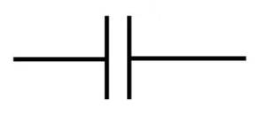
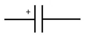
The capacitor symbol, with its distinctive appearance, stands out among the myriad of other symbols in circuit diagrams. It consists of two parallel lines separated by a gap, akin to the metal plates found inside a capacitor. These plates, when charged, store electrical energy temporarily, allowing capacitors to perform a wide range of functions in electronic circuits.· +
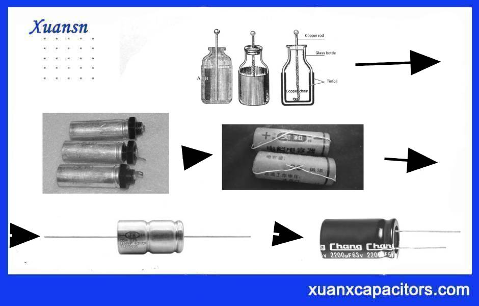
The history of the capacitor symbol dates back to the early days of electrical engineering, where inventors and engineers sought a visual representation that would convey the capacitor’s core properties without ambiguity. Over time, international organizations like the International Electrotechnical Commission (IEC) and the American National Standards Institute (ANSI) worked to standardize this symbol, ensuring consistency across circuit diagrams worldwide.
Understanding the Capacitor Symbol
The simple layout of the capacitor symbol holds valuable information about its function and characteristics. The two parallel lines represent the conductive plates of a capacitor, while the space between them symbolizes the insulating material, also known as the dielectric. It is this dielectric that allows the capacitor to store electric charge, as it resists the flow of charge between the plates.
Moreover, the placement and alignment of the lines in the capacitor symbol are intentional. The vertical alignment indicates that the capacitor is non-polarized, meaning it can be connected in either direction within a circuit. However, specialized capacitors, such as electrolytic capacitors, employ a unique symbol to denote polarity, preventing potential damage from incorrect connections.
Symbols for Different Types of Capacitors in Circuits
The circuit symbols of capacitors can be classified based on various factors, such as capacitor type, capacitance, polarity, and specific applications. Here’s a classification of capacitor circuit symbols:
1.Circuit symbol for non-polarized capacitors
The circuit symbol for a non-polarized capacitor is typically represented by two parallel lines with equal length, and no arrow or polarity markings. This symbol indicates that the capacitor is not polarity-sensitive, meaning it can be connected in either direction within the circuit.These capacitors include various types, such as ceramic capacitors, film capacitors (polyester, polypropylene, etc.), non-polarized tantalum capacitors, non-polarized aluminum electrolytic capacitors, supercapacitors, and certain variable capacitors used in tuning applications. They are widely used in electronic circuits for their versatility and flexibility in orientation. Always check the datasheet or product specifications to confirm the polarity characteristics of a capacitor and select the appropriate type based on the application requirements and voltage considerations for proper functioning and reliability.The following are common non-polarized capacitor symbols:
2.Circuit symbol for polarized capacitors
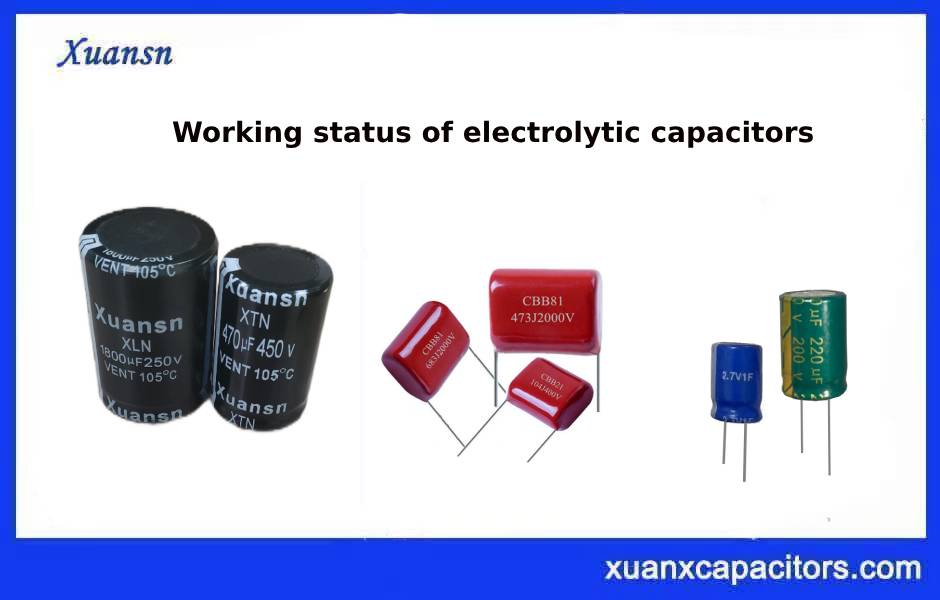
Polarized capacitors have specific positive (+) and negative (-) terminals, making them sensitive to polarity in a circuit. There are two main types: electrolytic capacitors (often made of aluminum or tantalum) and tantalum capacitors. They offer high capacitance in compact sizes and are commonly used in power supply circuits and portable electronics. Proper orientation is crucial, and connecting them in reverse can cause serious issues, so it’s essential to follow polarity markings and consult datasheets for voltage ratings to ensure safe and reliable operation.
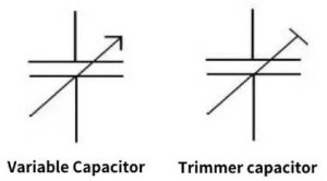
3.Circuit symbol for Variable capacitors
Variable capacitors are adjustable capacitors that allow manual or electronic changes to their capacitance. They are commonly used in radio-frequency circuits for tuning and resonance adjustments. Trimmer capacitors are a type of variable capacitor used for precise calibration. They come in air or ceramic dielectric types, and their capacitance can be adjusted mechanically or electronically. Variable capacitors are essential for frequency control in electronic devices and are widely used in radios, oscillators, filters, and tuning systems.
How to distinguish the positive and negative poles of electrolytic capacitors?
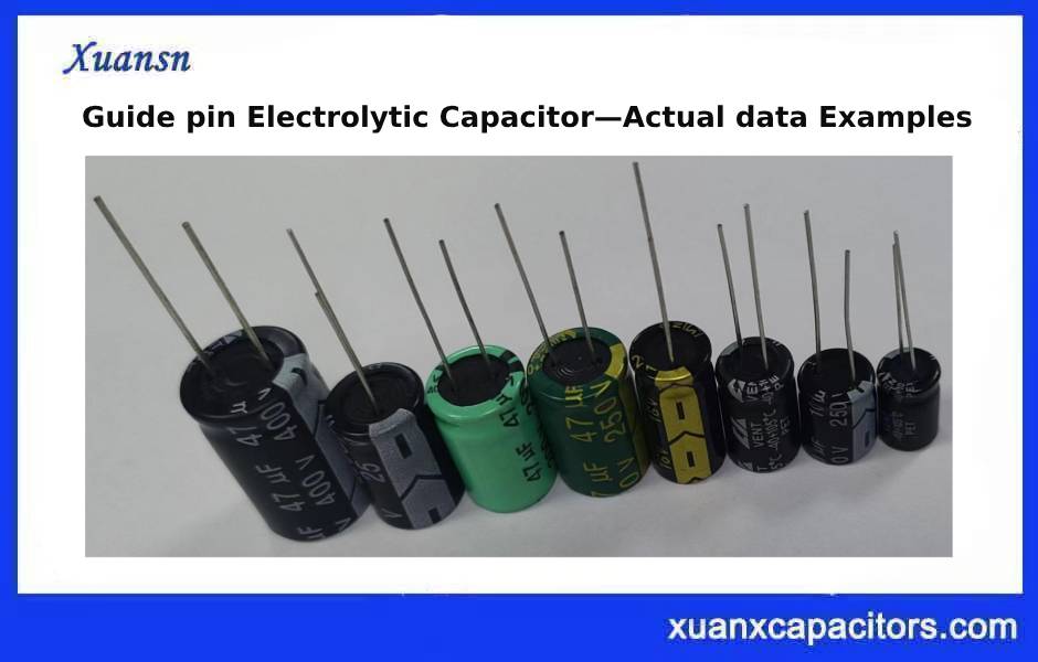
Distinguishing the positive and negative poles of electrolytic capacitors is essential to ensure proper and safe operation in a circuit. Electrolytic capacitors are polarized, meaning they have specific positive (+) and negative (-) terminals, and connecting them in reverse can cause catastrophic failures. Here’s how to identify the positive and negative poles of electrolytic capacitors:
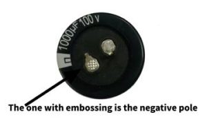
Look for Markings: Most electrolytic capacitors have clear markings indicating their polarity. The negative terminal is usually denoted by a stripe or arrow running down the side of the capacitor, indicating the negative (-) lead. Sometimes the positive terminal may have a “+” symbol, but the stripe is a more common indicator for the negative side.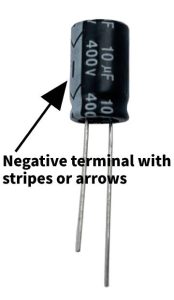
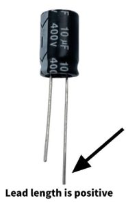
Longer Lead: Electrolytic capacitors often have one lead longer than the other. The longer lead typically corresponds to the positive (+) terminal, while the shorter lead is the negative (-) terminal.
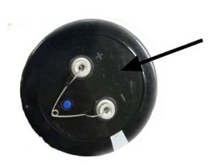
Case Shape: In some cases, the shape of the capacitor case can provide a clue about polarity. The negative terminal of some aluminum electrolytic capacitors may have a slightly flat or indented shape compared to the positive terminal, which may have a rounded shape.
Datasheet: If the capacitor is still in its packaging or you have access to its datasheet, it will provide clear information on the polarity.
Remember to always double-check the markings and confirm the polarity before connecting the capacitor to your circuit. Connecting the capacitor in reverse can lead to overheating, leakage, or even explosion in extreme cases. Be cautious and ensure the correct polarity is observed.
How to use a multimeter to measure the positive and negative electrodes of capacitors
Measuring the positive and negative poles of a capacitor using a multimeter is a straightforward process. However, it’s essential to handle capacitors with care, especially if they might still hold a charge. Follow these steps to measure the polarity of a capacitor using a digital multimeter:
Note: Before proceeding, make sure the capacitor is fully discharged and disconnected from any power source.
Step 1: Set the Multimeter to Capacitance Mode
- Turn on your digital multimeter (DMM).
- Select the capacitance mode (usually denoted by “F” for Farads) on the dial or function setting of your multimeter.
Step 2: Discharge the Capacitor (if needed)
- To ensure your safety, discharge the capacitor if it’s still holding a charge. You can do this by connecting a resistor across its terminals. Alternatively, you can use a low-voltage power supply (around 5V) to gradually discharge the capacitor.
Step 3: Identify the Terminals
- Look at the capacitor to find the markings or labels that indicate the positive and negative terminals. Common symbols include “+” or “POS” for the positive terminal and “-” or “NEG” for the negative terminal.
- If there are no markings on the capacitor, look for the longer leg or the one with a stripe or indentation; this typically indicates the negative (-) terminal. The other leg would be the positive (+) terminal.
Step 4: Place the Multimeter Leads
- Take the black (common) lead of the multimeter and connect it to the negative (-) terminal of the capacitor.
- Take the red (positive) lead of the multimeter and connect it to the positive (+) terminal of the capacitor.
Step 5: Read the Display
- Once the multimeter leads are correctly connected, the display should show the capacitance value, which indicates the polarity of the capacitor. If the reading is positive, then the red lead is on the positive terminal and the black lead on the negative terminal.
Step 6: Reverse the Leads (Optional)
- If the multimeter displays a negative capacitance value, it means you’ve swapped the leads. Simply reverse the leads: connect the red lead to the negative terminal and the black lead to the positive terminal.
- The multimeter should now display the positive capacitance value, indicating the correct polarity.
Step 7: Verify the Polarity
- After identifying the positive and negative terminals, double-check that they are indeed correct based on the capacitor’s markings or other labeling methods.
Remember, always be cautious when working with capacitors, especially when they might still be charged. If you’re unsure about any step or if you’re dealing with high-voltage capacitors, consider seeking assistance from a qualified professional.