Bionic Drag Reduction for Box Girders Based on Ostracion cubicus


1
School of Mechanical Engineering, Southwest Jiaotong University, Chengdu 610031, China
2
Technology and Equipment of Rail Transit Operation and Maintenance Key Laboratory of Sichuan Province, Chengdu 610031, China
*
Author to whom correspondence should be addressed.
Energies 2020, 13(17), 4392; https://doi.org/10.3390/en13174392
Submission received: 21 July 2020
/
Revised: 18 August 2020
/
Accepted: 24 August 2020
/
Published: 26 August 2020
Abstract
:With the development trend of large-scale and flexible structures in engineering, the research on drag reduction of structures becomes more urgent. This paper presents a drag reduction design method for box girders based on the bionic method. Through the analysis of the Ostracion cubicus body shape, three features of the “fish mouth”, which were helpful for drag reduction were extracted. Then the bionic design model with the height of the box girder (D) as the design variable was obtained. By attaching lightweight materials to the windward side, the bionic shape of the structure can be realized without changing the loading characteristics of the original structure. Taking a box girder (rectangular cylinder, side ratio B/D = 0.6) as a prototype, the flow around two structures (rectangular cylinder and bionic attachment cylinder) was numerically simulated. The results show that the drag coefficient of the bionic attachment structure is reduced by 66.5%. The reduction of wind-load means that this method can save energy consumption of the equipment. Meanwhile, the aerodynamic parameter oscillation of the structure is weakened, which represents that the bionic attachment structure can effectively reduce the wind-induced vibration on the structure and improve the stability of the structure in the wind field.
1. Introduction
In recent years, the engineering structure presents the development trend of being large-scale and flexible, and the influence of wind on the structure becomes more prominent. Therefore, structural drag reduction has gradually become a hot topic in engineering fluid mechanics. Drag reduction is also an important method of engineering energy saving. For example, the operation motor load of a 2000 t gantry is mainly composed of three parts: static resistance 267.54 kN, ramp operation resistance 133.77 kN and wind resistance 335.155 kN. The wind load accounts for 40–60% of the operating mechanism load and 10–20% of the structure load. Therefore, the drag reduction design for the box girder of the crane can reduce the energy consumption of the crane operation and achieve the goal of consumption reduction.
An effective structure drag reduction method is to generate a thin layer of gas or bubble cloud on the surface to reduce the shear stress, and delay the flow separation when flowing around the bluff body. Lubricating gas layers can be generated by different mechanisms, such as surface superhydrophobicity (Sooraj et al. [1]); microbubble injection and supercavitation (Ceccio and Steven [2]) or surface heating (Vakarelski et al. [3]; Arrieta and Sevilla [4]). Aiming at the drag reduction in engineering, the interaction mechanism between surfactant and gas–liquid two-phase flow was studied experimentally by Yin et al. [5]. The results show that the addition of surfactant weakens the strong gas–liquid interaction at the front end of the liquid plug and increases the reflux velocity in the liquid film. Zhang et al. [6] studied the flow, drag reduction and heat transfer characteristics of xanthan gum (XG) solution in corrugated and circular tubes. The results show that the characteristics of drag reduction in the corrugated tube are quite different from those in the circular tube through the strong turbulence disturbance on the inner wall.
The above drag reduction methods are mostly for internal flow or two-phase flow. Besides that, many scholars are committed to the external flow drag reduction. These drag reduction technologies can effectively achieve the goal of energy saving and consumption reduction. Minelli et al. [7] studied the control of local separation (on the side of the fuselage) and downstream wake dynamics by manipulating the leading-edge shear flow of the bluff body, thereby reducing the overall drag and improving lateral stability. Buljac et al. [8] investigated the influences of the rear wing height at four different positions on the aerodynamic loads and flow characteristics for an automobile. It is found that the rear wing is beneficial to the traction and stability of the vehicle, but increases the resistance, which is unfavorable to the fuel consumption. Kang [9] developed an active translational rear diffuser device to reduce the air resistance of passenger cars, and analyzed the aerodynamic drag reduction mechanism of the device. Chen et al. [10,11] studied the effects of structural motion and inclined angle of a slender prism on unsteady aerodynamic parameters. The results showed that the influences of structural motion on the coefficients are significant in the crosswind direction, but slight in the along-wind direction. Some experimental studies on the aerodynamics of bluff bodies are summarized by Grosche and Meier [12]. It includes that: (a) reducing drag by passive ventilation of the body wake, (b) reducing vehicle drag by shape optimization to eliminate or at least reduce the rear vortex, (c) optimizing the front and rear ends of high-speed trains, (d) identifying the main source of high-speed aerodynamic noise generated by unsteady flow separation and (e) experimental studies on active control of delayed separation. Lee [13] used the lattice Boltzmann (LBM) method to study the drag reduction of the road vehicle by the jet wheel deflector system, and evaluated the drag reduction performance. A method for reducing aerodynamic drag of a three-dimensional simplified vehicle by designing a synthetic jet array was experimentally studied by Park et al. [14]. Typical examples of such applications include flows past transportation vehicles, from automobile to aircraft. Dong et al. [15] studied the drag reduction mechanism of the re-entry aircraft with the concept of the spike and lateral jet combinational under the freestream at Mach number 5.9332. Mirzaei et al. [16] studied the flow pattern and drag reduction mechanism of a certain type of cargo aircraft, and simulated the drag reduction through the wind tunnel test and computational fluid dynamics (CFD) simulation. The results show that the improvement of the hull cross-section profile near the inclined door and the turning up angle of the stern can effectively reduce the drag coefficient, and CFD can be used as a reliable tool for resistance calculation and aircraft shape design.
Some scholars used bionic technology to simulate the drag reduction characteristics of organisms, and have achieved good drag reduction effect. Bionic drag reduction has very important applications, such as using groove surface drag reduction to imitate shark scale structure [17], and imitating insect unsmoothed surface for drag reduction [18]. Through the bionic research on the groove structure of shark skin, this kind of structure has been widely used, such as for the wings of an aircraft. Viswanath [19] and Lee and Jang [20], experimentally investigated the flow structure of the wake behind a wing covered with a V-shaped microriblet film. The results show that the surface friction drag reduction rate of the two-dimensional airfoil is between 5% and 8% under a low angle of attack and mild back pressure gradient. Dou et al. [21] simulated the microstructure of the fish scale surface by coating, and compared the flow parameters of the bionic surface and smooth surface in the water tunnel. Studies have shown that under the influence of surface morphology, the gas phase develops on the solid–liquid interface of the bionic surface, and partially replaces the solid–liquid shear force with gas–liquid shear force, thereby effectively reducing the surface friction resistance. Gu et al. [22] studied the drag reduction mechanism of a shark. The study found that when sharks swim, they discharge water and foam through their gill slit on the front gill plate, which helps to reduce the resistance of a shark swimming. This is similar to the mechanism of the drag reduction method mentioned above to generate a thin gas layer on the surface of the structure. Wang et al. [23] realized the drag reduction bionic design of the box girder by simulating the structure of Ostracion cubicus. However, the bionic contour obtained by polynomial fitting has some limitations, which cannot realize the smooth transition of structural joints and cannot be adjusted according to different operating conditions.
To sum up, the research on drag reduction in engineering is mainly divided into two parts: internal flow drag reduction such as oil pipeline, and external flow drag reduction such as automobile drag reduction. The drag reduction methods include structural surface treatments (such as the hydrophobic surface, bionic V-shaped groove, etc.), shape optimization (such as edge fillet treatment of windward side) and bionic methods (such as imitating shark skin and gills). The box girder in engineering is an external flow field, and its structure is mostly made of metal plate welding. It is difficult and costly to treat the structural surface or add the jet mechanism. This paper proposed a method to optimize the design of box girder by simulating the shape of Ostracion cubicus. The bionic profile model based on the height of the box girder (D) was established. Then the flow characteristics of the two structures (rectangular cylinder and bionic attachment cylinder) were analyzed by the CFD method.
2. Bionic Attachment Scheme
2.1. Bionic Feature Analysis
Ostracion cubicus (Figure 1a) is short and thick, and its body is box shaped, therefore it is commonly known as “box fish”. Interestingly, its box shape structure does not affect its movement speed. The Ostracion cubicus has formed a low flow resistance shape and a high-strength skeleton in the long-term evolution process. Some scholars have carried out experimental and simulation studies on the aerodynamic characteristics of the box fish (Kozlov et al. [24], Wassenbergh et al. [25] and Boute et al. [26]). Ostracion cubicus seems to use the interaction of the unstable body and orientation of the caudal fin to modulate stability, and the drag coefficient of the simplified box fish structure is around 0.1. Its unique and excellent biological characteristics have been used for reference in the field of automobile. Chowdhury et al. [27] applied certain aerodynamic features of the Ostracion cubicus to the shape of the vehicle and a prototype was manufactured. The drag coefficient of the prototype vehicle is as low as 0.28.
A side view of the Ostracion cubicus was shown in Figure 1b. The structure of the Ostracion cubicus can be divided into three parts: “fish mouth”, “fish body” and “fish tail”. The structure of the “fish body” is similar to that of box girders. The low flow resistance of the Ostracion cubicus is related to the "fish mouth" structure and the fillet transition surface at the top of the “fish body”. The structural features of the "fish mouth" make the front end of its contour have a long inclined arc, which can effectively reduce the impact force of the fluid and the separation of the boundary layer. The “fish tail” is mainly responsible for providing the power and steering when the Ostracion cubicus is swimming. Therefore, the bionic design focuses on the extraction of the Ostracion cubicus “fish mouth” characteristic structure.
Edge detection usually uses convolution and similar methods to detect the edge by capturing the maximum value of the gradient in the image by using the gray jump of the image at the edge. There are a large number of black and green spots on the Ostracion cubicus. The focus of this investigation is the streamline contour body edge of the Ostracion cubicus rather than the contour of the internal spots. The original image must be processed with noise and converted to gray scale before edge detection (Figure 1c). Then Canny edge detection was used to extract the edge contour and get the Ostracion cubicus contour (Figure 1d) [28]. From Figure 1e, we can distinguish the structural characteristics of Ostracion cubicus more intuitively. The section of the “fish body” is approximately rectangular, which can be compared to the box girder.
Through the analysis of the structural characteristics of the “fish mouth” outline, the structural characteristics of the “fish mouth” are mainly composed of three circle arcs and their connecting lines (Figure 1f). Therefore, these three circular arcs and their relative positions will become the key parameters of the bionic design. Compared with the polynomial fitting method [23], the parametric design method proposed in this paper has the advantages of a smooth transition of structure joint and easy adjustment according to different working conditions.
2.2. Feature Structure Expression
As Figure 2a shows, the streamline structure design parameters of the Ostracion cubicus “fish mouth” are the location and radius of characteristic circles (circle , and ). According to the three feature structures, the curve of “fish mouth” structure can be divided into seven line segments (–). Each line segment is tangent to their neighbors, where are arcs and are straight lines. () is a circular arc, one end of which is tangent to circle (), and the other end is tangent to the flange plate of the box girder. The characteristic parameter setting of the “fish mouth” structure is shown in Figure 2b. Take the joint between the “fish mouth” and the bottom of the “fish body” as the coordinate origin (), the direction from the fish mouth to the tail is the axis, and the direction from the bottom of the fish body to the top is the axis. The center positions and radius of circles , and are the initial characteristic parameters (B1, B2, B3; D1, D2, D3; R1, R2 and R3). The radius () of () is the intermediate parameter, which can be calculated by the geometric relationship between line segments.
The analytical expression of segment is given by
where and the start–finish interval of the line-segment is
Similarly, the analytical expression of – can be obtained. The analytic expressions for is
where the start–finish interval of the line-segment is
and
The formulas of , and in Equations (2)–(4) are shown in Table 1.
where the start–finish interval of the line-segment is
and
The analytic expressions for is
where the start–finish interval of the line-segment is
and
The formulas of , and in Equations (4)–(6) are shown in Table 1.
The analytic expressions for is
where the start–finish interval of the line-segment is
and
The analytic expressions for is
where the start–finish interval of the line-segment is
and
The analytic expressions for is
where and the start–finish interval of the line-segment is
2.3. Bionic Scheme Design
Figure 3 shows the structural diagram of a 40 t gantry crane box beam. The box girder of gantry cranes is mostly the rectangular cross-section, which is mainly composed of upper and lower flange plates and webs on both sides. The inner part is set with diaphragm and longitudinal stiffeners to enhance the local stability of the box girder, and a trolley track is installed on the top of the upper flange plate. The spreader, wire rope of the crane lifting mechanism will run in the space outside the inner web of the box girder. Generally, no functional mechanism is installed outside the outer web of the box girder. Therefore, the utilization of the outer space of the windward web (outer web) will not affect the operation of the mechanism.
Currently, there are mature and stable metal structure design methods in engineering. The adjustment of the metal structure will affect the load-bearing characteristics and operation safety of the structure. This can be achieved by attaching lightweight materials to the windward side [23], (as Figure 4 shows). The bionic profile equations are given in Section 2.2.
Lightweight materials can be made of organic polymers, such as expanded polystyrene (EPS) foam, which are lightweight, inexpensive, easy to process, transport and install and have a long life and so on. EPS is a lightweight polymer, which has the characteristics of low water absorption, stable chemical properties and good machinability, and has been widely used in civil engineering. This material does not produce large deformation under the action of wind load, which can fully meet the use requirements. Due to the good deformability of this kind of material, the adhesion of the box girder surface does not affect its operation. It can also play a beautifying effect. The attached structure does not affect the loading state of the box girder and the operation of the lifting mechanism.
The shape of the attachment structure is determined by Equations (1)–(7), in which the parameters (B1, B2 and B3; D1, D2 and D3 and R1, R2 and R3) are determined based on the height of the box girder (D). The corresponding design parameters can be obtained according to the conversion ratio in Table 2. The coefficients in Table 2 are obtained from the profile in Figure 1.
3. Numerical Details and the Governing Equations
The flow characteristics of the bionic attachment structure and the traditional box girder were simulated by CFD. The prototype of the box girder is a rectangular cylinder with a side ratio of 0.6 (B/D, refer to Figure 3), and the bionic profile equation was obtained from Equations (1)–(7). Considering that most of the box girders in engineering application are slender structures, the flow in different sections has a certain similarity. The two-dimensional simulation model was used in this investigation for verification and analysis. By analyzing the flow characteristics of the bionic structure and comparing with the original one, the effect of load reduction and vibration suppression of the bionic one can be verified.
3.1. Problem Description and Boundary Conditions
The geometry of the flow domain and boundary conditions are shown in Figure 5. The bionic attachment cylinder was set in the Cartesian coordinate system, and the -axis was in the same direction of inlet flow. The height of the cylinder (D) was equal to 1 m and all dimensions were based on this parameter. The width of the rectangular cylinder (B) was equal to 0.6 D.
The computational boundary conditions of the flow field were set as: (a) uniform velocity inlet U = 10 m/s; (b) pressure outlet P = 0 Pa; (c) symmetry for top and bottom boundaries and (d) no-slip wall on the surface of the cylinder. The Reynolds number of the flow was 6.85 × 10⁵, and the turbulence intensity was set to 5%.
3.2. Numerical Calculation Governing Equations
Turbulence is described by the Navier–Stokes (N–S) equation in principle. Reynolds applied averaging procedures to filter out the turbulent spectrum for solving N–S equations (Reynolds-averaged N–S, RANS). Due to the introduction of additional unknown terms in the RANS method, the N–S equation cannot be closed. Based on the Boussinesq hypothesis [29], Shin proposes the realizable model that satisfies certain mathematical constraints on the Reynolds stresses [30]. The transport equations of the realizable model for the thermostatic and incompressible flow are
and
where is the fluid density; is the kinetic energy of turbulence; is the rate of dissipation of turbulence kinetic energy; is the fluid viscosity; is the eddy viscosity; , is the component of velocity in and directions; , are the coefficients and is the source term with the following values
3.3. Definition of Parameters
The aerodynamic coefficients of the cylinder are defined as
The formulae for the Reynolds and Strouhal numbers are
The time-average and root-mean-square of the aerodynamic coefficients are calculated as follows (use the as an example)
where is the drag force; is the lift force; is the pressure; is the height of cylinder; is the width of cylinder; is the length of cylinder; is the fluid kinetic viscosity; is the frequency of vortex shedding and is the fluctuation period.
3.4. Model Validation and Grid Independence Study
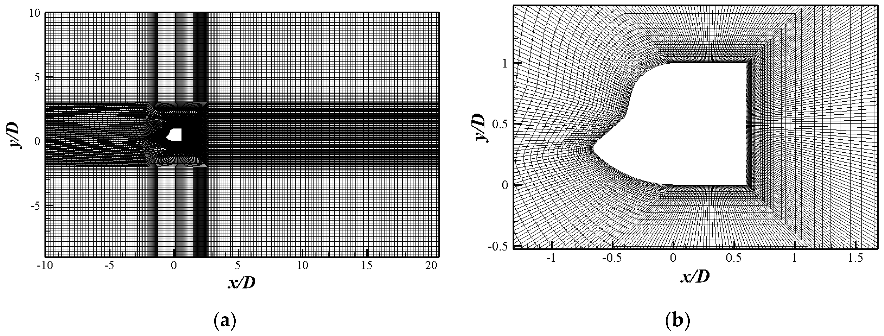
Figure 6a shows the non-uniform grid of the cylinder, and Figure 6b is the detailed enlarged view of grid division around the cylinder. The orthogonal grid was used in the calculation, and densification around the cylinder with the O-block grid. The calculation used the PISO (Pressure Implicit with Splitting of Operators) algorithm. Firstly, the flow around a rectangular cylinder with side ratio of 0.6 was calculated at Re = 6.85 × 10⁵. Three sets of grid models with different density (G1, G2 and G3) were established to calculate the flow around the rectangular cylinder with a width height ratio of 0.6. Then the calculation results were compared with the reference values to ensure the accuracy of the numerical simulation. Numerical results are shown in the Table 3.
The simulation results of the three grids are in good agreement with the experimental values (Norberg [31] and Nakaguchi [32]) and LES simulation results (Sohankar [33]), which proves that the simulation method of the numerical model in this paper was reliable. At the same time, the difference between the results of the three sets of grids was less than 10%. In the following, the calculation results of G2 grid were selected for discussion.
4. Results and Discussion
4.1. Aerodynamic Parameters
Figure 7 shows the comparison of the aerodynamic coefficients of the two structures. The time-average drag coefficient () is usually used to measure the wind-load of the structures. In Figure 7, of the box girder with the bionic attachment structure was reduced from 2.69 to 0.901. This means that the bionic attachment scheme could greatly reduce the wind resistance of the box girder. The parametric design of the attachment model proposed in this paper had a lower drag coefficient than the previous study [23], (), because the transition between the attached structure and the box girder was smoother.
The amplitude of aerodynamic coefficient represents the oscillation of the aerodynamic force on the structure, which is related to the wind-induced vibration and impact of the structure in the flow field. The amplitude was equal to half of the difference between the maximum and minimum values of the parameter. The amplitude of the lift coefficient with the bionic attachment structure was reduced from 1.95 to 0.416 (decreased by 78.67%), which means that the bionic attachment structure had better stability in the flow field. Similarly, the amplitudes of drag and torque coefficients (, ) were also greatly reduced, which were 59.3% (from 0.182 to 0.074) and 95.2% (from 0.532 to 0.040), respectively.
The root-mean-square of lift coefficient (Cl,rms) represents the wind load stability of the structure. Compared with the rectangular cylinder, Cl,rms of the bionic attachment structure was reduced from 2.046 to 0.150 (see in Table 4). The increase of St in the bionic attachment cylinder indicates that the vortex shedding frequency at the wake of the structure increased. This is because the streamline shape of the attached structure makes the boundary layer separation point move forward, which reduced the wake width and made the wake get more energy. The size of the wake vortices became smaller. The back pressure coefficient (Cpb) of the structure changed from −2.162 to −0.866. Cpb represents the pressure loss caused by the obstruction of the structure to the flow field. It shows that the bionic attachment structure can reduce the obstruction of the box girder to the flow field.
4.2. Aerodynamic and Flow Characteristics
4.2.1. Pressure Coefficients Distribution
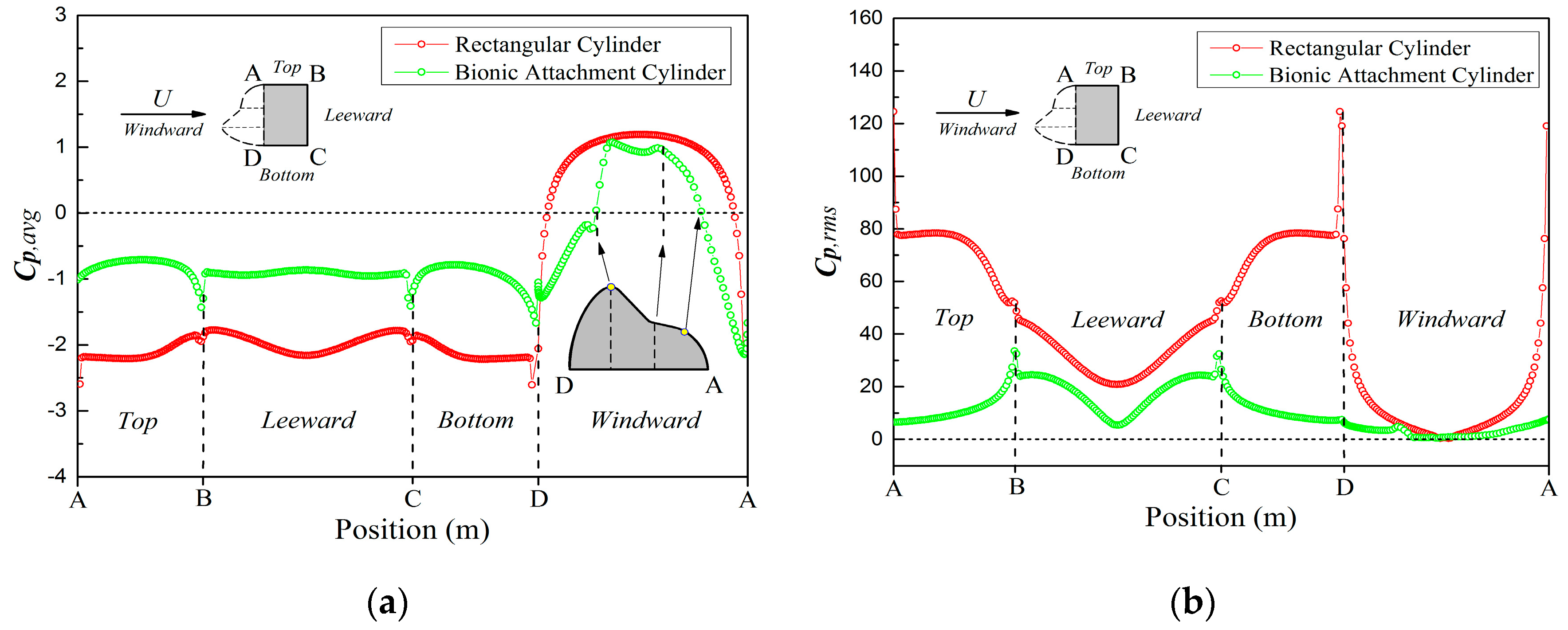
Figure 8a presents the time-average pressure coefficient (Cp,avg) around the two structures. The transition position from the positive to negative values of Cp,avg represents the separation point of the boundary layer. On the windward surface, the boundary layer separation points of the rectangular cylinder were around A and D, while those of the bionic attachment cylinder were at and (see in Figure 2a). The moving forward of the boundary layer separation points reduced its width and weakened the blocking effect of the structure on the fluid. Cp,avg of the top-surface was negative, and the value of the bionic attachment cylinder decreased. The bottom and leeward surface showed the same trend.
The root-mean-square pressure coefficient (Cp,rms) in Figure 8b represents the stability of the structure under the wind load. Cp,rms of the bionic attachment cylinder was relatively stable, and the larger value around point B and C were due to the separation of fluids. The Cp,rms of the rectangular cylinder was large at the top and bottom surface, and pretty high around point A and D. This is because the boundary layer separated at points A and D, and formed vortices on the top and bottom surface of the structure.
4.2.2. Velocity Distribution
The distribution of time-average stream-wise x-velocity (uavg) along the centerline of the structure is shown in Figure 9a. The centerline is a line along the x-axis in the middle of the structure (y = 0.5 m) of the flow field. For the rectangular cylinder, uavg stagnated at zero on the windward side of the structure, and transited from negative to positive on the leeward side. Compared with the rectangular cylinder, the transition point was further to the leeward side, which meant that the wake vortex was further to the leeward side. In the wake far away from the structures, uavg of the bionic attachment cylinder was larger and closer to the inlet velocity (U = 10 m/s). This meant that the obstruction of the bionic attachment structure to the fluid was reduced, and the energy of the wake was enhanced. The root-mean-square velocity (urms) represents the fluctuation intensity of velocity. urms of the rectangular cylinder had a large peak behind the leeward side, while urms of bionic attachment cylinder was low and stable (Figure 9b). It shows that the streamline shape of bionic attachment structure has less influence on the flow field.
It can be seen from Figure 10a,b that the wake time-average velocity decreased as the distance increased. The wake region affected by the flow around the bionic attachment cylinder was narrower and shorter (see in particular enlarged drawing ). It shows that the bionic attachment structure had little effect on the flow field of the tail. The multi peak of the curve shown in enlarged drawing indicates the existence of vortices. The wake vortex of the rectangular cylinder was disappeared after x/D = 0.3, while that of the bionic attachment structure was disappeared after x/D = 1.6.
The root-mean-square velocity distribution of the wake represents the turbulence of the wake flow field (Figure 10c,d). Near the leeward side of the rectangular cylinder, the wake presented a strong velocity oscillation, which reduced the stability and caused wind-induced vibration of the structure in the wind field. The maximum amplitude of urms of the rectangular cylinder appeared at x/D = 0.6, while the results of the bionic attachment structure was appeared at x/D = 1.6 (see in particular enlarged drawing). Additionally, the value of urms of the rectangular cylinder was much higher than that of the bionic attachment structure. It means that the bionic attachment structure can effectively reduce the disturbance of the structure to the flow fields.
4.3. Flow Field Evolution
Figure 11 gives the flow visualization images of the two structures flow field evolution. The time-average streamlines boundary layer separation occurred at both ends of the windward side of the rectangular cylinder, and reattachment was formed at the tail of the cylinder. Vortices were formed at the top-leeward-bottom surface of the cylinder (Figure 11a). For the attachment structure, the boundary layer separation occurred on the windward side, flowed along the top and bottom surface and separated from the ends of the leeward side of the structure. Compared with the rectangular cylinder, the wake vortex of the attachment structure was more backward, which was consistent with the results in Figure 9a. From the instantaneous streamline contours of Figure 11a,b, it can be found that the bionic attachment structure flow field was more stable. The vortex shedding began at both ends of the windward side of the rectangular cylinder (Figure 11c), and the width of vortex street was wider than that of bionic attachment structure (Figure 11d). For the attachment structure, vortex shedding appeared at the ends of the leeward side, and the vortices became smaller and more numerous (see in Figure 11e,f).
4.4. Analysis of the Bionic Drag Reduction Effect
According to the above simulation results of the flow characteristics of the two structures, the drag reduction effect of the attachment structure was evaluated. In the calculation example of the 40 t crane, the height of the box girder was 2 m, the length of the main beam was 40 m and the attached structure area was 1.666 m2 (see Figure 3). The calculation of the wind load on the structure can be obtained from Equation 10, where D = 2 m, L = 40 m, U = 10 m/s and = 1.23 kg/m3. The drag coefficients of the two structures can be obtained from Figure 7 (Traditional box girder- and Bionic attachment-). The attachment structure was selected as EPS, which the density was about 20 kg/m3. The comparison between the two structures is shown in Table 5.
Although the bionic box girder with the EPS adhesive increased the weight of the original box girder by 4.87%, it reduced the wind load by 66.5%. The structural wind-load is an important part of the crane operating load. The bionic design method can greatly reduce the power of running motors, and thus reduce energy consumption.
In the meantime, according to the discussion in Section 4.1, the oscillation amplitudes of , and were reduced by 59.3%, 78.67% and 95.2%, respectively. This is due to the streamline structure of the bionic attachment box girder that reduced the flow field disturbance caused by the boundary layer separation. Therefore, the bionic attachment structure reduced the structural vibration caused by turbulence and improved the stability of the mechanism.
5. Conclusions
From the point of structural drag reduction, a bionic wind load reduction design method of the box girder attached structure inspired by the structure of the Ostracion cubicus was proposed. Based on the feature extraction of the Ostracion cubicus’ “fish mouth”, the contour equation of the attached structure with the structure height (D) as the design variable was established. Lightweight material attached to the windward side of the box girder can reduce the wind load without changing the mechanical bearing characteristics of the box girder. The numerical simulation of the flow characteristics around a traditional box girder (rectangular cylinder, side ratio B/D = 0.6) and the corresponding bionic attachment structure at Re = 6.85 × 10⁵ was carried out.
The bionic attachment structure can effectively reduce the wind-load of the box girder. The time-average drag coefficient () of the box girder with the bionic attachment structure is reduced from 2.69 to 0.901. The bionic box girder with the EPS attachment material could reduce the load by 66.5%. At the same time, the weight of the attached structure only increased by 4.85%, which had little effect on the load of the structure. The bionic attachment structure could greatly reduce the power of running motors, and therefore save energy.
The streamline shape of the bionic attachment structure could greatly reduce the vibration and shock of the structure in the flow field. For the bionic attachment structure, the oscillation amplitude of the aerodynamic parameters (, and ) was greatly reduced, and the pressure coefficient (Cp,avg and Cp,rms) was lower. The more stable force of the flow field on the structure means that the wind-induced vibration effect of the structure was weakened. The Strouhal number (St) increased from 0.117 to 0.183, indicating that the frequency of vortex shedding increased. Vortex shedding appeared at the ends of the leeward side, and the vortices became smaller and more numerous. In the wake far away from the structures, uavg of the bionic attachment cylinder was larger and closer to the inlet velocity (U = 10 m/s). This means that the obstruction of the bionic attachment structure to the fluid was reduced, and the energy of the wake was enhanced. The separated fluid flowed along the surface of the structure and separated from the upper and lower edges of the leeward surface, which not only reduced the resistance of the structure, but also reduced the width of the wake vortex street.
In conclusion, the streamline shape of bionic attachment structure made the fluid flow attach to the structure surface. The boundary layer separation point of the flow field moved forward from the corner of the windward side of the box girder to the attached structure, and the width was reduced. As a result, the structure resistance and flow field disturbance were reduced. The drag reduction of the box girder could greatly reduce the motor load of equipment operation and save energy. Meanwhile, the bionic attachment structure could reduce the wind-induced vibration of the structure and improve the stability of the structure in the wind field.
Author Contributions
Y.W., conceptualization, methodology, software, formal analysis, validation, investigation, data curation of the bionic drag reduction method, and writing—original draft preparation; W.C., supervision, project administration, and funding acquisition; R.D., software, validation, investigation of the bionic drag reduction method, and writing—review and editing; S.W., methodology, software, data curation of the bionic drag reduction method, and writing—review and editing. All authors have read and agreed to the published version of the manuscript.
Funding
This research was funded by National Natural Science Foundation of China (NSFC), grant number 51675450.
Conflicts of Interest
The authors declare no conflict of interest.
References
- Sooraj, P.; Ramagya, M.S.; Khan, M.H.; Sharma, A.; Agrawal, A. Effect of superhydrophobicity on the flow past a circular cylinder in various flow regimes. J. Fluid Mech. 2020, 897, 1–31. [Google Scholar] [CrossRef]
- Ceccio, S.L. Friction Drag Reduction of External Flows with Bubble and Gas Injection. Annu. Rev. Fluid Mech. 2010, 42, 183–203. [Google Scholar] [CrossRef] [Green Version]
- Vakarelski, I.U.; Berry, J.D.; Chan, D.Y.; Thoroddsen, S.T. Leidenfrost Vapor Layers Reduce Drag without the Crisis in High Viscosity Liquids. Phys. Rev. Lett. 2016, 117, 114503. [Google Scholar] [CrossRef] [PubMed] [Green Version]
- Arrieta, J.; Sevilla, A. On the flow separation mechanism in the inverse Leidenfrost regime. J. Fluid Mech. 2020, 897, 1–18. [Google Scholar] [CrossRef]
- Yin, P.; Cao, X.; Wu, C.; Qin, S.; Zhang, P.; Bian, J. The effect of surfactants on the initiation and development of air–water slug flow in hilly terrain pipeline. Exp. Therm. Fluid Sci. 2020, 117, 110139. [Google Scholar] [CrossRef]
- Zhang, Y.; Zhou, F.; Kang, J. Flow and heat transfer in drag-reducing polymer solution flow through the corrugated tube and circular tube. Appl. Therm. Eng. 2020, 174, 115185. [Google Scholar] [CrossRef]
- Buljac, A.; Džijan, I.; Korade, I.; Krizmanić, S.; Kozmar, H. Automobile aerodynamics influenced by airfoil-shaped rear wing. Int. J. Automot. Technol. 2016, 17, 377–385. [Google Scholar] [CrossRef] [Green Version]
- Minelli, G.; Dong, T.; Noack, B.R.; Krajnović, S. Upstream actuation for bluff-body wake control driven by a genetically inspired optimization. J. Fluid Mech. 2020, 893, 1–29. [Google Scholar] [CrossRef]
- Kang, S.O.; Jun, S.O.; Park, H.I.; Song, K.S.; Kee, J.D.; Kim, K.H.; Lee, D.H. Actively translating a rear diffuser device for the aerodynamic drag reduction of a passenger car. Int. J. Automot. Technol. 2012, 13, 583–592. [Google Scholar] [CrossRef]
- Chen, Z.S.; Tse, K.T.; Kwok, K.C.S. Unsteady pressure measurements on an oscillating slender prism using aforced vibration technique. J. Wind Eng. Ind. Aerodyn. 2017, 170, 81–93. [Google Scholar] [CrossRef]
- Chen, Z.-S.; Tse, K.T.; Kwok, K.C.S.; Kareem, A. Aerodynamic damping of inclined slender prisms. J. Wind Eng. Ind. Aerodyn. 2018, 177, 79–91. [Google Scholar] [CrossRef]
- Grosche, F.-R.; Meier, G.E.A. Research at DLR Göttingen on bluff body aerodynamics, drag reduction by wake ventilation and active flow control. J. Wind Eng. Ind. Aerodyn. 2001, 89, 1201–1218. [Google Scholar] [CrossRef]
- Lee, S.W. Computational analysis of air jet wheel deflector for aerodynamic drag reduction of road vehicle. Microsyst. Technol. 2018, 24, 4453–4463. [Google Scholar] [CrossRef]
- Park, H.; Cho, J.H.; Lee, J.; Lee, D.H.; Kim, K.H. Experimental study on synthetic jet array for aerodynamic drag reduction of a simplified car. J. Mech. Sci. Technol. 2013, 27, 3721–3731. [Google Scholar] [CrossRef]
- Dong, M.; Liao, J.; Du, Z.; Huang, W. Influences of lateral jet location and its number on the drag reduction of a blunted body in supersonic flows. Aeronaut. J. 2020, 124, 1055–1069. [Google Scholar] [CrossRef]
- Mirzaei, M.; Karimi, M.H.; Vaziri, M.A. An investigation of a tactical cargo aircraft aft body drag reduction based on CFD analysis and wind tunnel tests. Aerosp. Sci. Technol. 2012, 23, 263–269. [Google Scholar] [CrossRef]
- Lin, Y.T.; Ting, Y.S.; Chen, B.Y.; Cheng, Y.W.; Liu, T.Y. Bionic shark skin replica and zwitterionic polymer brushes functionalized PDMS membrane for anti-fouling and wound dressing applications. Surf. Coat. Technol. 2020, 391, 125663. [Google Scholar] [CrossRef]
- Tian, L.M.; Ren, L.Q.; Liu, Q.P.; Han, Z.W.; Jiang, X. The mechanism of drag reduction around bodies of revolution using bionic non-smooth surfaces. J. Bionic Eng. 2007, 4, 109–116. [Google Scholar] [CrossRef]
- Viswanath, P.R. Aircraft viscous drag reduction using riblets. Prog. Aerosp. Sci. 2002, 38, 571–600. [Google Scholar] [CrossRef] [Green Version]
- Lee, S.-J.; Jang, Y.-G. Control of flow around a NACA 0012 airfoil with a micro-riblet film. J. Fluids Struct. 2005, 20, 659–672. [Google Scholar] [CrossRef]
- Dou, Z.; Wang, J.; Chen, D. Bionic research on fish scales for drag reduction. J. Bionic Eng. 2012, 9, 457–464. [Google Scholar] [CrossRef]
- Gu, Y.; Zhao, G.; Zheng, J.; Li, Z.; Liu, W.; Muhammad, F. Experimental and numerical investigation on drag reduction of non-smooth bionic jet surface. Ocean Eng. 2014, 81, 50–57. [Google Scholar] [CrossRef]
- Wang, Y.P.; Cheng, W.M.; Du, R.; Wang, S.B.; Deng, Y. Bionic design method for crane box girder wind load reduction based on ostracion-cubicus. J. Southwest Jiaotong Univ. 2020, 55, 664–671. [Google Scholar] [CrossRef]
- Kozlov, A.; Chowdhury, H.; Mustary, I.; Loganathan, B.; Alam, F. Bio-Inspired Design: Aerodynamics of Boxfish. Procedia Eng. 2015, 105, 323–328. [Google Scholar] [CrossRef] [Green Version]
- van Wassenbergh, S.; van Manen, K.; Marcroft, T.A.; Alfaro, M.E.; Stamhuis, E.J. Boxfish swimming paradox resolved: Forces by the flow of water around the body promote manoeuvrability. J. R. Soc. Interface 2015, 12, 20141146. [Google Scholar] [CrossRef] [PubMed] [Green Version]
- Boute, P.G.; van Wassenbergh, S.; Stamhuis, E.J. Modulating yaw with an unstable rigid body and a course-stabilizing or steering caudal fin in the yellow boxfish (Ostracion cubicus). R. Soc. Open Sci. 2020, 7, 1–15. [Google Scholar] [CrossRef] [Green Version]
- Chowdhury, H.; Islam, R.; Hussein, M.; Zaid, M.; Loganathan, B.; Alam, F. Design of an energy efficient car by biomimicry of a boxfish. Energy Procedia 2019, 160, 40–44. [Google Scholar] [CrossRef]
- Canny, J. A Computational Approach to Edge Detection. IEEE Trans. Pattern Anal. Mach. Intell. 1986, 8, 679–698. [Google Scholar] [CrossRef]
- Hinze, J.O. Turbulence; McGraw-Hill Publishing, Co.: New York, NY, USA, 1975. [Google Scholar]
- Shih, T.-H.; Liou, W.W.; Shabbir, A.; Yang, Z.; Zhu, J. A new k-ϵ eddy viscosity model for high reynolds number turbulent flows. Comput. Fluids 1995, 24, 227–238. [Google Scholar] [CrossRef]
- Norberg, C. Flow around rectangular cylinders: Pressure forces and wake frequencies. J. Wind Eng. Ind. Aerodyn. 1993, 49, 187–196. [Google Scholar] [CrossRef]
- Nakaguchi, H.; Hashimoto, K.; Muto, S. An Experimental Study on Aerodynamic Drag of Rectangular Cylinders. J. Jpn. Soc. Aeronaut. Space Sci. 1968, 16, 1–5. [Google Scholar] [CrossRef]
- Sohankar, A. Large eddy simulation of flow past rectangular-section cylinders: Side ratio effects. J. Wind Eng. Ind. Aerodyn. 2008, 96, 640–655. [Google Scholar] [CrossRef]
Figure 1.
The geometry of the flow domain and boundary conditions.

Figure 2.
Characteristic analysis of the “fish mouth” of Ostracion cubicus. (a) Characteristic analysis and (b) characteristic parameter setting.
Figure 2.
Characteristic analysis of the “fish mouth” of Ostracion cubicus. (a) Characteristic analysis and (b) characteristic parameter setting.

Figure 3.
Structural diagram of a 40 t gantry crane box beam.

Figure 4.
Bionic attachment scheme.

Figure 5.
The geometry of the flow domain and boundary conditions.

Figure 6.
Non-uniform grid of the cylinders in O-block type. (a) Global meshing and (b) O-block mesh refinement.
Figure 6.
Non-uniform grid of the cylinders in O-block type. (a) Global meshing and (b) O-block mesh refinement.

Figure 7.
Comparison of the aerodynamic coefficients of the two structures.

Figure 8.
Pressure coefficient distribution around cylinders. (a) Time-average pressure coefficient and (b) root-mean-square pressure coefficient.
Figure 8.
Pressure coefficient distribution around cylinders. (a) Time-average pressure coefficient and (b) root-mean-square pressure coefficient.

Figure 9.
Distributions of stream-wise velocity along the centerline of the structure. (a) Time-average velocity and (b) root-mean-square velocity.
Figure 9.
Distributions of stream-wise velocity along the centerline of the structure. (a) Time-average velocity and (b) root-mean-square velocity.

Figure 10.
Velocity distributions of wake: (a,b): time-average velocity and (c,d): root-mean-square velocity. (a) Rectangular cylinder; (b) bionic attachment cylinder; (c) rectangular cylinder and (d) bionic attachment cylinder.
Figure 10.
Velocity distributions of wake: (a,b): time-average velocity and (c,d): root-mean-square velocity. (a) Rectangular cylinder; (b) bionic attachment cylinder; (c) rectangular cylinder and (d) bionic attachment cylinder.

Figure 11.
Flow visualization images: (a,b): time-average streamlines contours; (c,d): instantaneous streamlines contours and (e,f): vorticity contours. (a) Rectangular cylinder (b) bionic attachment cylinder; (c) rectangular cylinder; (d) bionic attachment cylinder; (e) rectangular cylinder and (f) bionic attachment cylinder.


Table 1.
Expression of the intermediate symbol.
| Symbol | α1 | β1 | λ1 | α2 | β2 | λ2 |
|---|---|---|---|---|---|---|
| Expression | R1 + R2 | B2 − B1 | D2 − D1 | R2 + R3 | B3 − B2 | D3 − D2 |
Table 2.
Conversion scale of each parameter.
| Parameter | B1 | B2 | B3 | D1 | D2 | D3 | R1 | R2 | R3 |
| Value | 0.1D | 0.45D | 0.6D | 0.3D | 0.4D | 0.7D | 0.25D | 0.05D | 0.06D |
Table 3.
Comparison of numerical results.
| Examples | No. | Number of Grids | Re/×105 | Cd,avg | St | Cpb |
|---|---|---|---|---|---|---|
| Rectangular Cylinder | G1 | 28632 | 6.85 | 2.687 | 0.122 | −2.153 |
| G2 | 47128 | 6.85 | 2.690 | 0.117 | −2.162 | |
| G3 | 59120 | 6.85 | 2.702 | 0.116 | −2.165 | |
| Norberg [31], (EXP) | 0.13 | 2.78 | 0.123 | −2.32 | ||
| Nakaguchi [32], (EXP) | 0.6 | 2.72 | 0.116 | −2.02 | ||
| Sohankar [33], (LES) | 1.0 | 2.72 | 0.144 | −2.04 | ||
| 5.0 | 2.70 | - | - | |||
Table 4.
Comparison of the aerodynamic coefficients.
| Cl,rms | St | Cpb | |
|---|---|---|---|
| Rectangular Cylinder | 2.046 | 0.117 | −2.162 |
| Bionic Attachment Cylinder | 0.150 | 0.183 | −0.866 |
Table 5.
Comparison of wind load between the two structures.
| Traditional Box Girder | Bionic Attachment Structure | Reduction Ratio | |
|---|---|---|---|
| Windward area (m2) | 80 | 80 | - |
| Weight (kg) | 27,361 | 28,694 | +4.87% |
| Wind load (kN) | 13.235 | 4.43 | −66.5% |
© 2020 by the authors. Licensee MDPI, Basel, Switzerland. This article is an open access article distributed under the terms and conditions of the Creative Commons Attribution (CC BY) license (http://creativecommons.org/licenses/by/4.0/).
Share and Cite
MDPI and ACS Style
Wang, Y.; Cheng, W.; Du, R.; Wang, S. Bionic Drag Reduction for Box Girders Based on Ostracion cubicus. Energies 2020, 13, 4392. https://doi.org/10.3390/en13174392
AMA Style
Wang Y, Cheng W, Du R, Wang S. Bionic Drag Reduction for Box Girders Based on Ostracion cubicus. Energies. 2020; 13(17):4392. https://doi.org/10.3390/en13174392
Chicago/Turabian StyleWang, Yupu, Wenming Cheng, Run Du, and Shubiao Wang. 2020. "Bionic Drag Reduction for Box Girders Based on Ostracion cubicus" Energies 13, no. 17: 4392. https://doi.org/10.3390/en13174392
Note that from the first issue of 2016, this journal uses article numbers instead of page numbers. See further details here.