
Electrolytic capacitors are a type of fixed capacitor. They are discussed separately from standard fixed capacitors because they differ significantly from them and are widely used in circuits.
1.1 Explanation of Types and Structures of Electrolytic Capacitors
1. Explanation of Types of Electrolytic Capacitors
The table illustrates the classification methods for electrolytic capacitors.
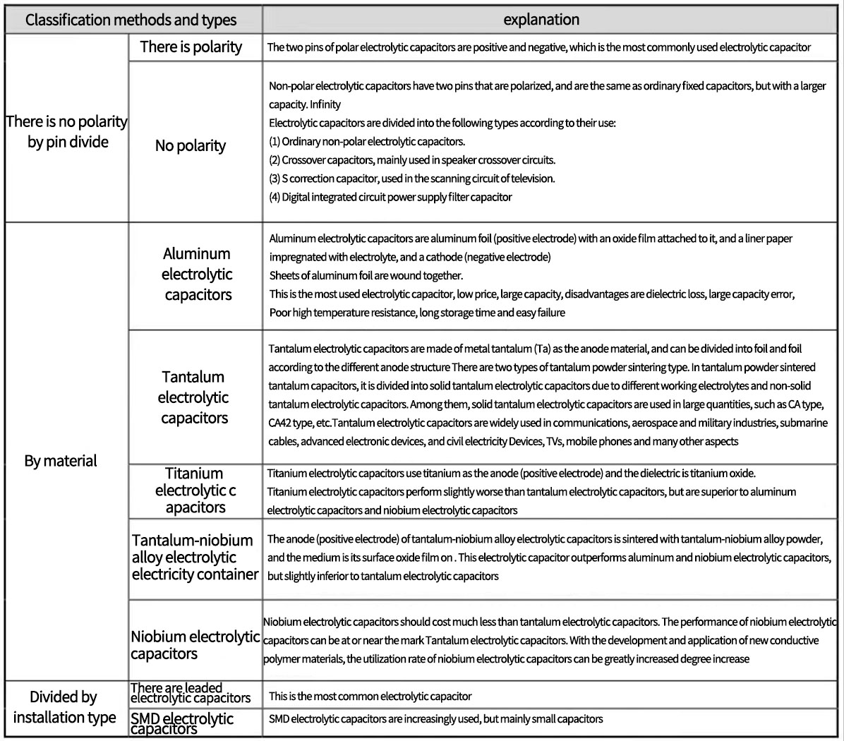
Explanation of how electrolytic capacitors are categorized
2. Explanation of the Structure and Working Principle of Polarized Electrolytic Capacitors
The structure of polarized electrolytic capacitors differs from that of non-polarized electrolytic capacitors. Due to this structural difference, the two types of electrolytic capacitors have different lead polarities.
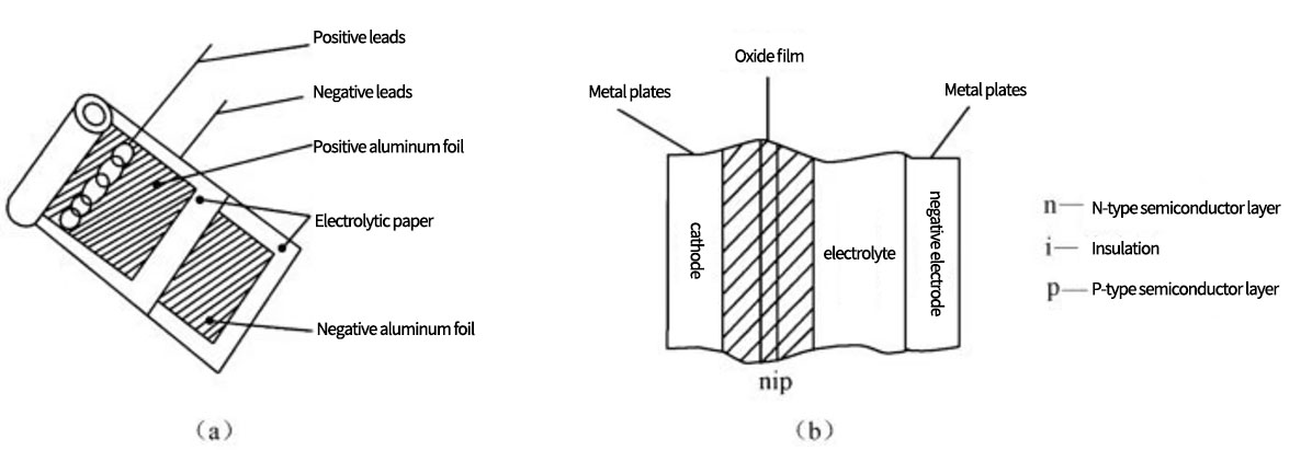
The figure shows the internal structure of a polarized electrolytic capacitor. Figure (a) depicts an aluminum electrolytic capacitor, using two layers of aluminum foil as the positive and negative plates of the capacitor, with positive and negative leads respectively drawn from them.
Between the two aluminum foils, an electrolytic paper is used to insulate the plates. The entire foil is then tightly rolled up, impregnated with a working electrolyte (mostly a paste-like liquid), and sealed in an outer casing. This constitutes the structure of a polarized electrolytic capacitor.
In Figure (b), the dielectric of this type of capacitor is an oxide film, similar to the PN junction in transistors, exhibiting unidirectional conductivity. When the positive lead of the electrolytic capacitor is connected to a high potential and the negative lead to a low potential, the oxide film is in a blocking state, similar to the reverse bias state of a PN junction. The current between the positive and negative plates is minimal, and the electrolytic capacitor operates normally.
Polarized electrolytic capacitor internal structure schematic diagram
When the negative lead is connected to a high potential and the positive lead to a low potential, the oxide film is in a conducting state, similar to the forward conduction of a PN junction. The current between the plates is significant, and the capacitor loses its function. Note that reversing the leads in this manner can also cause the capacitor to explode.
The polarity of the capacitor is due to its internal structure, which resembles a PN junction. A polarized electrolytic capacitor can only operate normally when a reverse voltage is applied to this "PN junction", as shown in the figure.
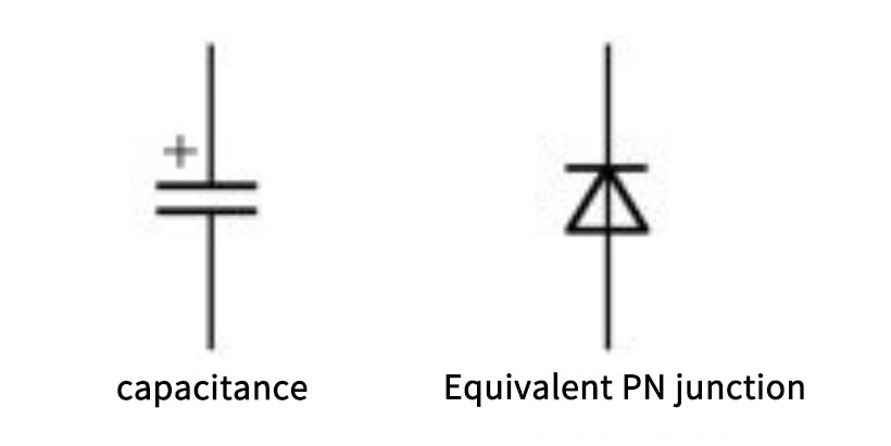
Equivalent schematic of PN junction of polarized electrolytic capacitor
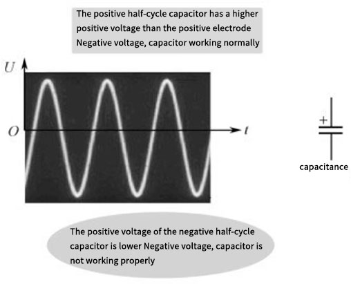
Because of the polarity of the leads of the polarized electrolytic capacitor, it cannot be used in pure AC circuits. As shown in the figure, if it is used in a pure AC circuit, it will operate in a reverse polarity state for half of the cycle, damaging the polarized electrolytic capacitor.
Schematic diagram of pure AC circuit
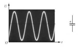
In electronic circuits, AC voltage signals typically "ride" on DC voltage, as shown in the figure. The entire voltage remains positive, so the negative half-peak voltage of the AC voltage is also positive, ensuring no negative voltage occurs. Thus, using a polarized electrolytic capacitor in such a circuit poses no issues.
3. Explanation of the Structure and Working Principle of Non-Polarized Electrolytic Capacitors
Non-polarized electrolytic capacitors, also known as bipolar electrolytic capacitors, have a structure illustrated in Figure.
Schematic structure of non-polarized electrolytic capacitor
From the figure, it's evident that this type of capacitor has two oxide films, one being nip and the other pin. It's akin to having two PN junctions back-to-back. In this way, regardless of which lead, either positive 1 or positive 2, is connected to a high potential and the other to a low potential, one of the oxide films will always be in a conducting state, and the other in a blocking state. This ensures minimal current flow between the plates, overcoming the limitation of having distinct positive and negative leads in polarized electrolytic capacitors.
Non-polarized electrolytic capacitors, due to their dual oxide film structure, make the leads non-polar while retaining some advantages of electrolytic capacitors. However, non-polarized electrolytic capacitors are more expensive than their polarized counterparts, with some being significantly pricier.
Electrolytic capacitors are favored for their small size, large capacitance, and low cost (compared to other types of capacitors). However, the distinct positive and negative leads of polarized electrolytic capacitors limit their applications, while non-polarized electrolytic capacitors, despite being more expensive, can overcome these limitations.
1.2 Explanation of Polarity Identification Methods for Polarized Electrolytic Capacitors
1. Methods to Identify the Polarity of Polarized Electrolytic Capacitors
Electrolytic capacitors typically use the direct marking method to indicate nominal capacitance, allowable deviation, rated voltage, etc. For polarized electrolytic capacitors, the polarity of the leads is also marked.
The table shows the representation methods for the leads of polarized electrolytic capacitors.
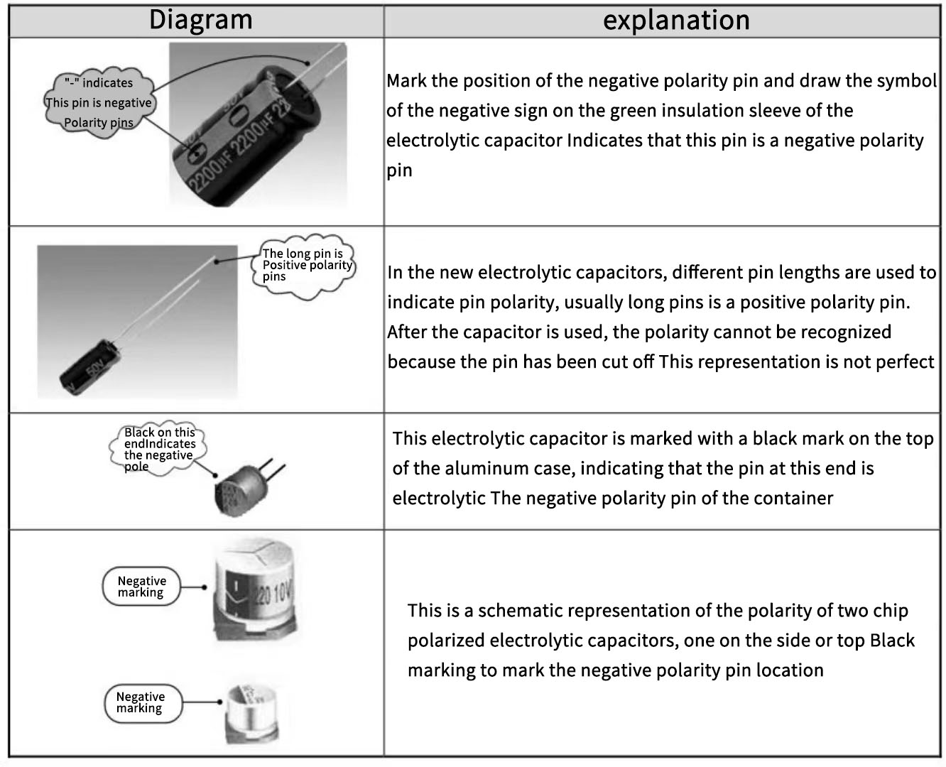
Explanation of the pinout of polarized electrolytic capacitors
2. Venting Feature of Electrolytic Capacitors
Electrolytic capacitors are equipped with a venting feature. The figure shows a chevron-shaped vent. There are also other designs like the cross shape, and some vents are located at the bottom, with various shapes.
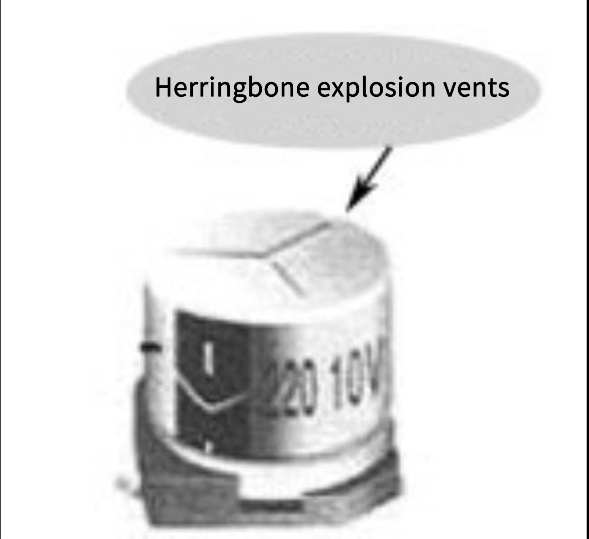
Herringbone Blast Port
Related Blogs

Categories
Feature Products
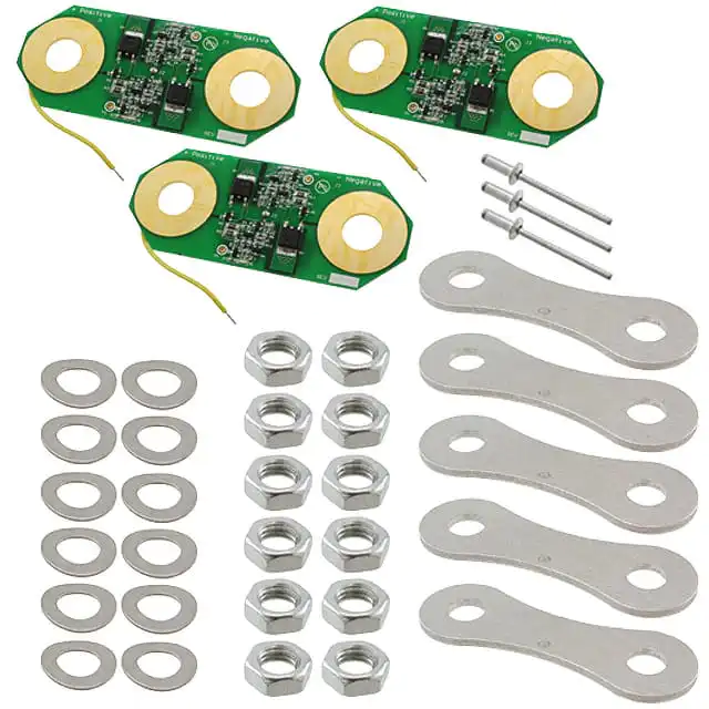
388-075
CAP PERM-O-PADS 6.9MM X 1.9MM
$0.113 VIEW MORE
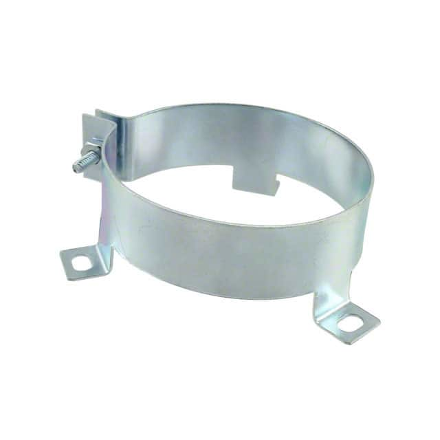
VR10A
MOUNTING CLAMP VERT 2.5IN DIA
$3.892 VIEW MORE
30393-5
CAP WRAP AROUND BRACKET OVAL
$2.368 VIEW MORE
VR3
MOUNTING CLAMP VERT 1.375IN DIA
$2.651 VIEW MORE
VR8A
MOUNTING CLAMP VERTICAL 2IN DIA
$3.502 VIEW MORE
VR8
MOUNTING CLAMP VERTICAL 2IN DIA
$3.502 VIEW MORE
32107-1
CAP MOUNTING BRACKET OVAL
$3.839 VIEW MORE
VR3A
MOUNTING CLAMP VERT 1.375IN DIA
$2.651 VIEW MORE
TH25
MOUNTING CLIP HORIZ 1.375IN DIA
$3.496 VIEW MORE
32107-2
CAP MOUNTING BRACKET OVAL
$4.748 VIEW MORE
125565-06
MNT BRACKET FOR ROUND CAN TYPES
$5.504 VIEW MORE
VR4A
MOUNTING CLAMP VERT 1.5IN DIA
$3.678 VIEW MORE
Subscribe To Receive Discounts And Latest Articles
- Purchase Inquiry: [email protected]
- Support: [email protected]


