With a worm gear, high loads can be transmitted at a high transmission ratio.
Operating principle
A special design of the gear wheel is the so-called worm. In this case, the tooth winds around the worm shaft like the thread of a screw. The mating gear to the worm is the worm gear. Such a gearbox, consisting of worm and worm wheel, is generally referred to as a worm drive.
The worm can be regarded as a special case of a helical gear. Imagine there was only one tooth on a helical gear. Now increase the helix angle (lead angle) so much that the tooth winds around the gear several times. The result would then be a “single-toothed” worm.
One could now imagine that instead of one tooth, two or more teeth would be wound around the cylindrical gear at the same time. This would then correspond to a “double-toothed” worm (two thread worm) or a “multi-toothed” worm (multi thread worm).
The “number of teeth” of a worm is referred to as the number of starts. Correspondingly, one speaks of a single start worm, double start worm or multi-start worm. In general, mainly single start worms are produced, but in special cases the number of starts can also be up to four.
Worms are basically spirally wound “teeth” that screw into the worm gear and drive it!
Transmission ratio
Since the number of starts is of a worm ultimately the equivalent to the number of teeth of a toothed wheels, the number of teeth to be used to determine the transmission ratio \(i\) corresponds to the number of starts of the worm:
\begin{align}
\label{uebersetzungsverhaeltnis}
&\boxed{ i = \frac{z_{\text{worm gear}}} {z_{\text{worm}}} } ~~~ \text{} z_{\text{worm}} = 1 … 4 ~~~\text{depending on the number of starts}\\[5px]
\end{align}
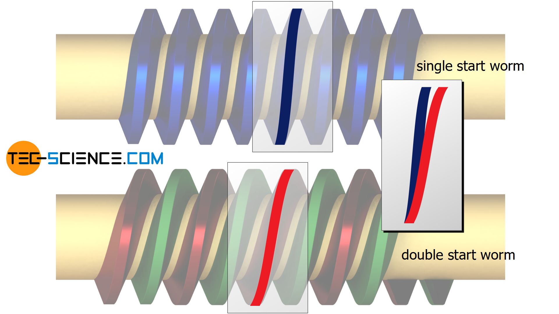
That the number of starts of a worm corresponds to the number of teeth of a cog wheel can also be seen clearly from the animation below of a single start worm drive. With one rotation of the worm the worm thread pushes straight on by one position. The worm gear is thus moved on by one tooth. Compared to a toothed wheel, in this case the worm actually behaves as if it had only one tooth around its circumference.
On the other hand, with one revolution of a two start worm, two worm threads would each move one tooth further. In total, two teeth of the worm wheel would have moved on. The two start worm would then behave like a two-toothed gear.
The animation below shows the comparison between a double start worm and the single start worm. Note that the worm gear driven by the double start worm rotates twice as fast as the worm gear of the single start worm (lower transmission ratio).
Due to the generally very low number of starts of the worm (usually one!) and the comparatively large number of teeth of the worm gear, the transmission ratio of worm drives is correspondingly very high. With worm drives, very high transmission ratios of more than 100 can be achieved in a space-saving manner!
Since several sections of the worm thread are generally engaged simultaneously while meshing with the worm gear, the load capacity of such worm drives is very high, i.e. very high power can be transmitted. In addition, worm drives are very quiet due to the continuous sliding of the flanks between worm and worm gear and the required lubrication or cooling (more on this in the following section).
Worm drives are very space-saving and are suitable for transmitting high power at high transmission ratios!
Power transmission
In worm drives, power is transmitted almost exclusively through sliding between the flanks of the worm and the worm gear, i.e. the flanks slide onto each another as a screw. Worms are ultimately a special case of screw gears. In contrast to screw gears, which generate a point-shaped flank contact, worms have a linear flank contact. This results in the advantage of transmitting higher power at higher transmission ratios.
Due to the sliding processes and the associated friction on the flanks, the efficiency of worm drives is generally lower than wirh spur gear drives or bevel gear drives. Due to the heat generated by friction, worm drives must be cooled at high power transmissions in addition to lubrication.
Worm types
Depending on the shape of the worm, worm drives can be classified differently.
Cylindrical worms
If the external shape of the worm has a cylindrical design, the worm is called a cylindrical worm. If the worm gear maps this cylindrical profile in the cross-section of the circumference, the gear wheel is called globoid worm gear. Due to the relatively simple production of a cylindrical worm, this variant is preferably used (cylindrical worm drive).
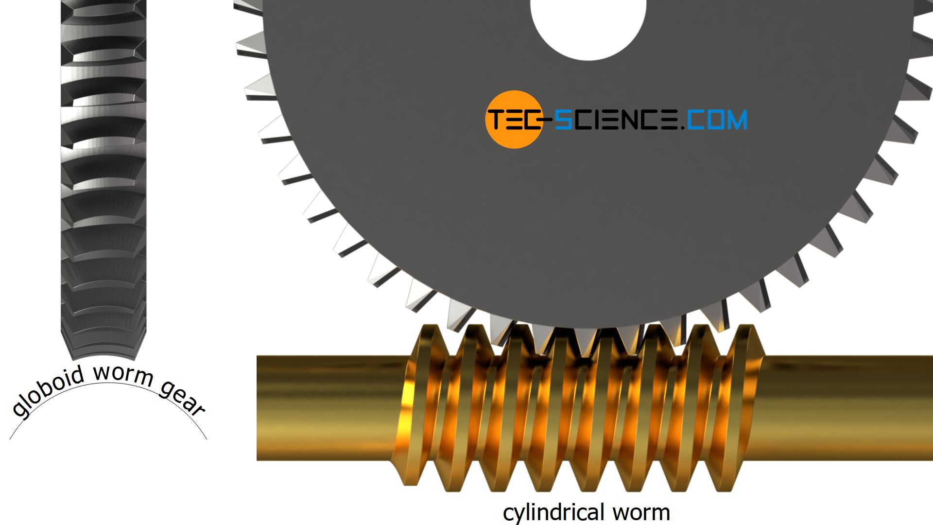
Cylindrical worms are relatively easy to produce and are preferred for cost reasons!
Globoid worms (enveloping worms)
In a modified variant, the external shape of the worm describes an arc which partly envelopes the globoid worm gear. One then speaks of a globoid worm or an enveloping worm (globoid worm drive).
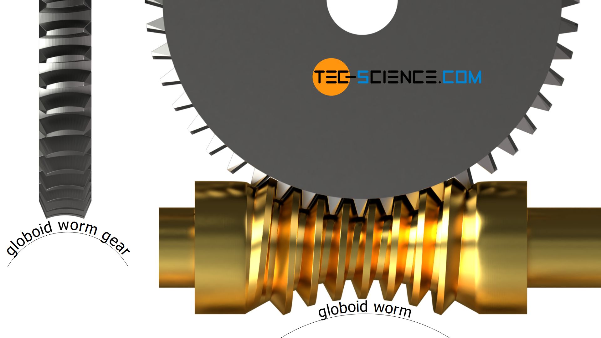
Compared to a cylindrical worm, with a globoid worm it is achieved by wrapping the worm wheel that more sections of the worm thread are involved in meshing. Globoid worms can thus transfer higher powers than cylindrical worms.
The production of a globoid worm is relatively complicated compared to a cylindrical worm and therefore expensive. Such globoid worms are therefore less used.
With globoid worms (enveloping worms) higher powers can be transmitted; however, they are relatively expensive due to the complex production!
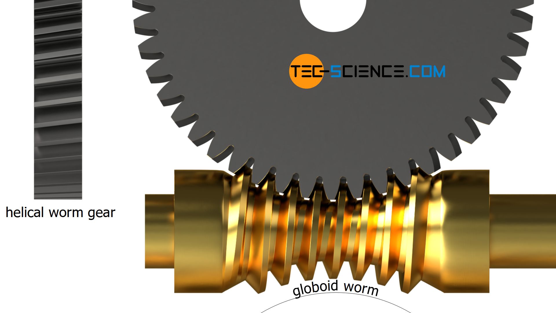
In special cases, the globoid worm can even be paired with a simple helical gear. However, this requires a special adaptation of the worm to the helical gear, which makes production correspondingly expensive. However, the advantage is the lower design effort, since the radial positioning of the worm when mating with a simple helical gear allows a greater tolerance than is the case with a globoid worm gear.
Self-locking
Transmissions are called self-locking if torque transmission can only take place in one direction. The gear unit can only be set in motion by the input shaft. However, the gear unit cannot be set in motion by the output shaft. Input and output are thus fixed.
Worm drives are often self-locking due to their special operating principle. This self-locking is due to the screw motion of the worm thread at low lead angles. Thus the worm can drive the worm wheel by its helical flank motion, but vice versa no motion can usually be produced. The contact force of the worm gear flanks against the thread flanks of the worm is so large and the lead angle just to small that the resulting frictional force prevents a rotational motion. For this reason, self-locking worm drives are always driven by the worm.
Self-locking worm drives can only be set in motion by the worm!
Note that the thread of a single start worm generally has a smaller lead angle than multi-start worms. Single start worms twist more and are therefore more often self-locking than multi start thread worms. Conversely, this means that self-locking can be prevented (if desired) with multi-thread worms.
Types of self-locking
Self-locking worm drives are used, for example, in lifting platforms. The self locking mechanism prevents the platform from moving down again on its own when the motor is switched off (statically self-locking). An additional holding brake can be dispensed with if the self-locking mechanism is large enough and cannot be released by any vibrations. If such a release should be the case, then often a “rattling” of the worm drive is to be noted.
Depending on the application, it must also be ensured that the gear unit stops automatically on its own if the motor is switched off when lowering the lifting platform (dynamically self-locking or self-braking).
As this example shows, a distinction must therefore be made between two types of self-locking:
- self-locking(statically self-locking)
“self-locking from the resting state” (static friction is not overcome) - self-braking (dynamically self-locking)
“self-braking rom the operating state” (sliding friction acts as a brake)
A gearbox is considered statically self-locking if it has come to a halt and cannot be set in motion by the worm wheel under a vibration-free state!
However, vibrations or shocks can eliminate this static self-locking mechanism and cause the gear unit to start up under output-side load.
A gearbox is considered self-braking (dynamically self-locking) if the disengaged gear comes to a halt after a short time when a load on the output is present (e.g. lowering a lifting platform).
Self-locking and efficiency
Self-locking is always associated with friction, without which there would otherwise be no self-locking. Self-locking gears therefore always have a lower efficiency than comparable non-self-locking gears. Usually the efficiency of self-locking worm drives is less than 50 %. Above 50 %, worm drives are often non-self-locking.
If self-locking is not required, the focus is usually on the highest possible efficiency. Efficiencies of well over 90 % are also possible for worm drives, but without self-locking in principle. However, if for economical reasons a high efficiency is required with “self-locking”, then the gearbox must be equipped with a holding brake.
As already explained, the individual threads of a multi-start worm have a larger pitch angle and thus a lower tendency to self-locking, since the friction forces are lower due to the reduced “wedge effect”. This increases the efficiency!
Multi-start worms have higher efficiencies and a lower tendency to self-locking!
Over travel
Self-locking can become problematic when large masses are moved with the worm wheel. If the worm drive is then suddenly switched off, the worm wheel is still trying to move due to the inertia of the driven mass. However, since the worm does not allow a rotational motion due to self-locking, enormous flank loads can occur and fracture the worm.
In such cases, the worm cannot be stopped abruptly, but must rotate a little bit further after switching off the gear drive (called over travel). Special lubricants can help the worm to over travel. It may also be necessary to implement special over traveling devices that bring the transmission slowly to a standstill.
If large masses are moved with worm drives, it must be ensured that the gear does not come to a standstill immediately after switching off!
")


")
")