EP0100975B1 - Massage apparatus - Google Patents
Massage apparatus Download PDFInfo
- Publication number
- EP0100975B1 EP0100975B1 EP19830107488 EP83107488A EP0100975B1 EP 0100975 B1 EP0100975 B1 EP 0100975B1 EP 19830107488 EP19830107488 EP 19830107488 EP 83107488 A EP83107488 A EP 83107488A EP 0100975 B1 EP0100975 B1 EP 0100975B1
- Authority
- EP
- European Patent Office
- Prior art keywords
- housing
- motor
- tool
- massaging
- tool carrier
- Prior art date
- Legal status (The legal status is an assumption and is not a legal conclusion. Google has not performed a legal analysis and makes no representation as to the accuracy of the status listed.)
- Expired
Links
Images

Classifications
-
- A—HUMAN NECESSITIES
- A61—MEDICAL OR VETERINARY SCIENCE; HYGIENE
- A61H—PHYSICAL THERAPY APPARATUS, e.g. DEVICES FOR LOCATING OR STIMULATING REFLEX POINTS IN THE BODY; ARTIFICIAL RESPIRATION; MASSAGE; BATHING DEVICES FOR SPECIAL THERAPEUTIC OR HYGIENIC PURPOSES OR SPECIFIC PARTS OF THE BODY
- A61H23/00—Percussion or vibration massage, e.g. using supersonic vibration; Suction-vibration massage; Massage with moving diaphragms
- A61H23/02—Percussion or vibration massage, e.g. using supersonic vibration; Suction-vibration massage; Massage with moving diaphragms with electric or magnetic drive
- A61H23/0254—Percussion or vibration massage, e.g. using supersonic vibration; Suction-vibration massage; Massage with moving diaphragms with electric or magnetic drive with rotary motor
- A61H23/0263—Percussion or vibration massage, e.g. using supersonic vibration; Suction-vibration massage; Massage with moving diaphragms with electric or magnetic drive with rotary motor using rotating unbalanced masses
Definitions
- the invention relates to a massage device, consisting of an electric drive motor on the shaft protruding from the motor housing, a flywheel is eccentrically attached, a to the motor housing at the end of the flywheel weight, optionally via a tool holder, attached and vibrating together with this massage tool, the motor and Massage tool and, if applicable, tool carrier existing vibration unit is elastically mounted in a housing at least partially enclosing the motor.
- the oscillating unit is mounted so that it can oscillate elastically on the housing by an elastic endless belt arranged in the longitudinal center of the motor, so that it describes a circular path about the longitudinal axis of the motor.
- a change of direction of this orbit is brought about, according to the further illustrations of this device, neither by the strip of elastic material additionally arranged at the end of the engine on the flywheel side, nor by the rubber spacer placed between the end of the engine which is turned away from the flywheel and the housing.
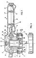
- FIG. 1 shows a longitudinal section of a massage device according to the invention
- FIG. 2 shows a cross section along lines II in FIG. 1
- FIG. 3 shows a variant of the elastic mounting for FIG. 2
- FIG. 4 shows a variant of the pivotable holder for FIG. 1
- FIG. 5 in longitudinal section a further massage device according to the invention
- FIG. 6 an insertable massage tool for the device according to FIG. 5 in view.
- the electric drive motor 1 is fastened to the housing 4 at the end applied to the flywheel weight 3 by the pivotable holder 6 and is elastically mounted 7 on the housing 4 in the region of the flywheel weight 3.
- the elastic mounting 7 consists of two rubber bolts 7 'arranged opposite one another, which are arranged between the tool carrier 15 fastened to the drive motor 1 and a housing part 4' which can be screwed onto the housing 4 by the screws 17.
- the rubber bolts 7 ' are screwed in at one end by vulcanized-in threaded bolts 14 on the shoulder 19 of the tool carrier 15 and at the other end by vulcanized-in nuts 16 and the screws 18 with the housing part 4'.
- the tool carrier 15 surrounding the flywheel 3 is connected to the drive motor 1 by the two screws 16 with the double-armed bracket 5, the pivotable holder 6 being arranged between the end of the bracket 5 and the housing 4.
- a rubber bolt 6 ' is provided with grub screws 14 which are vulcanized in on both sides, a grub screw being screwed onto the bracket 5 and the further grub screw being connected to the housing 4 by means of the screw 13 which is formed with an internal thread.
- the tool carrier 15 has a projection 15 ′ protruding from the housing 4, into which the massage tool 12 is screwed.
- the housing 4 is further provided with a half-shell-shaped projection, which together with another, by means of the screws 24 u.
- the half-shell-shaped housing part 4 "which can be screwed onto the housing 4 forms the handle 8.
- Three rechargeable battery batteries 10 are arranged in this, which drive the drive motor 1 via the on / off switch 11.
- the device plug socket 25 and a charger (not shown in detail) can be used for the Batteries 10 can be charged.
- the oscillation unit and thus also the massage tool 12 are transmitted by the arrangement mentioned a flat elliptical oscillating orbit, the larger semi-axis of the ellipse acting in the direction of arrow A (FIG. 2).
- a particularly powerful depth effect can be achieved with this device.
- the pivotable bracket 6 is designed as a dome joint 6 ', which is inelastic connected to the housing 4.
- the joint shell 20, which is fastened to the housing 4 has at the end a plurality of radial slots 21 through which the one with the double-armed bracket 5 integrally connected ball head 22 can be inserted. This prevents natural vibrations that would otherwise occur with an elastically pivotable bracket.
- the tool carrier 15 is arranged outside the housing consisting of the parts 4, 4 'and 4 ".
- the tool carrier 15 is also designed as a massage tool 12.
- the elastic mounting 7 consists of three on the housing part 4 'in the plane perpendicular to the longitudinal axis 2 of the motor, uniformly distributed rubber bolts 7' which are arranged between the housing part 4 'and the tool carrier 15 in such a way that the tool carrier 15 connects to the lower edge of the housing part 4' at a distance of a few millimeters. 4 "u. 4 "are connected by the screws 32 and 33 - the former indicated by the lines of symmetry - the housing parts 4 and 4" having lugs which together form the handle 8.
- rechargeable batteries 10 are also provided here, which are fastened to the housing part 4 by means of the cage 34 and are connected to the current through the on / off switch 11 and the cable 29. Further cable connections 27 are arranged between the batteries 10 and the device plug socket 26 used for charging.
- the tool carrier 15 is provided with bead-shaped projections 30, with which it can also be used as a massage tool.
- Other massage tools (12 ', FIG. 6) can also be arranged on it.
- this device is indicated by arrows A and B. Accordingly, the massage tool 12 is driven in a circular, oscillating manner and can therefore exert both a depth effect and a width effect. This effect is not changed even if the elements 7 used for elastic mounting are arranged perpendicular to the longitudinal axis 2 or if they are also loosely stored between the housing part 4 'and the massage tool 12 or the tool carrier 5.
- the configurations according to the invention are not limited to the exemplary embodiments shown, but arrangements of the same can also be interchanged or expanded.
- a further massage tool 12 in the axial direction 2 of the motor 1 to the extension 19 of the device shown in FIG. 1, so that massage movements can be transmitted to the body in two different directions.
- 15 elements 7 'or 7 can also be arranged, for example, a rubber bellows or the like.
- the number of revolutions of the drive motor can also be adjustable, or the flywheel weight can be mounted in the tool carrier 15 and, if necessary, a reduction gear can be driven by a counter gear.
Description
Die Erfindung betrifft ein Massagegerät, bestehend aus einem elektrischen Antriebsmotor an dessen aus dem Motorgehäuse herausragenden Welle ein Schwunggewicht exzentrisch angebracht ist, einem am Motorgehäuse an dessen schwunggewichtsseitigen Ende, gegebenenfalls über einen Werkzeugträger, befestigten und mit diesem zusammen schwingenden Massagewerkzeug, wobei die aus Motor und Massagewerkzeug und gegebenenfalls Werkzeugträger bestehende Schwingeinheit in einem den Motor zumindest teilweise umschließenden Gehäuse elastisch gelagert ist.The invention relates to a massage device, consisting of an electric drive motor on the shaft protruding from the motor housing, a flywheel is eccentrically attached, a to the motor housing at the end of the flywheel weight, optionally via a tool holder, attached and vibrating together with this massage tool, the motor and Massage tool and, if applicable, tool carrier existing vibration unit is elastically mounted in a housing at least partially enclosing the motor.
Bei einem bekannten Gerät dieser Art (US―A―2 113444) ist die Schwingeinheit durch ein in der Längsmitte des Motors angeordnetes elastisches Endlosband am Gehäuse elastisch schwingbar so gelagert, daß diese um die Längsachse des Motors eine Kreisbahn beschreibt. Eine Richtungsänderung dieser Umlaufbahn wird gemäß den weiteren Darstellungen dieses Gerätes weder durch den zusätzlich am schwunggewichtsseitigem Ende des Motors angeordneten Streifen aus elastischem Material, noch durch das zwischen dem dem Schwunggewicht abgewendeten Ende des Motors und dem Gehäuse dazwischen gelegte Distanzstück aus Gummi herbeigeführt.In a known device of this type (US ― A ― 2 113444), the oscillating unit is mounted so that it can oscillate elastically on the housing by an elastic endless belt arranged in the longitudinal center of the motor, so that it describes a circular path about the longitudinal axis of the motor. A change of direction of this orbit is brought about, according to the further illustrations of this device, neither by the strip of elastic material additionally arranged at the end of the engine on the flywheel side, nor by the rubber spacer placed between the end of the engine which is turned away from the flywheel and the housing.
Es ist Aufgabe der Erfindung, die Wirkung eines solchen Gerätes zu verbessern.It is an object of the invention to improve the effect of such a device.
Gelöst wird diese Aufgabe durch im kennzeichnenden Teil des Anspruches 1 angeführten Merkmale.This object is achieved by the features stated in the characterizing part of claim 1.
Durch diese Merkmale wird dem Massagewerkzeug eine im wesentlichen kreisförmig pendelnde Schwingbewegung übertragen; somit besteht gegenüber der genannten bekannten Ausbildung eine völlig andere Art der Führung für die Schwingeinheit. Ihre bessere Wirkung wird damit begründet, daß wegen der schwenkbaren Halterung der Mittelpunkt der elastischen Lagerung von der Motormitte zum schwunggewichtsseitigen Ende hin, d.h. zum Schwerpunktsbereich der Schwingeinheit, verlegt werden kann, welche Maßnahme zweifellos eine weitaus größere Ausschwenkung des Massagewerkzeuges zuläßt. Durch das Zusammenwirken der pendelartigen Aufhängung mit der elastischen Lagerung werden kraftvolle Schwingungen schon mit geringer Motorantriebsleistung erzielt. Weitere Ausgestaltungen der Erfindung sind in den Unteransprüche dargelegt. Sie betreffen insbesondere vorteilbringende Lösungen für die elastische bzw. pendelartige Lagerung der Schwingeinheit.These features transmit an essentially circular oscillating movement to the massage tool; thus there is a completely different type of guidance for the vibration unit compared to the known training. Their better effect is justified by the fact that, due to the pivotable mounting, the center of the elastic mounting from the motor center to the end towards the flywheel weight, i.e. to the center of gravity of the vibrating unit, which measure undoubtedly permits a far greater swiveling out of the massage tool. The interaction of the pendulum-like suspension with the elastic mounting enables powerful vibrations to be achieved even with low motor drive power. Further refinements of the invention are set out in the subclaims. They relate in particular to advantageous solutions for the elastic or pendulum-like mounting of the vibration unit.
Die Erfindung wird anhand von zwei Ausführungsbeispielen näher erläutert. Es zeigen: Fig. 1 im Längsschnitt ein erfindungsgemäßes Massagegerät, Fig. 2 einen Querschnitt nach den Linien I-I in Fig. 1, Fig. 3 eine Variante der elastischen Lagerung für Fig. 2, Fig. 4 eine Variante der schwenkbaren Halterung für Fig. 1, Fig. 5 im Längsschnitt ein weiteres erfindungsgemäßes Massagegerät und Fig. 6 ein einsetzbares Massagewerkzeug für das Gerät nach Fig. 5 in Ansicht.The invention is explained in more detail using two exemplary embodiments. 1 shows a longitudinal section of a massage device according to the invention, FIG. 2 shows a cross section along lines II in FIG. 1, FIG. 3 shows a variant of the elastic mounting for FIG. 2, FIG. 4 shows a variant of the pivotable holder for FIG. 1, FIG. 5 in longitudinal section a further massage device according to the invention and FIG. 6 an insertable massage tool for the device according to FIG. 5 in view.
In Fig. 1 u. 2 ist erfindungsgemäß der elektrische Antriebsmotor 1 an dem dem Schwunggewicht 3 angewandten Ende durch die schwenkbare Halterung 6 am Gehäuse 4 befestigt und im Bereich des Schwunggewichtes 3 elastisch 7 am Gehäuse 4 gelagert. Wie in Fig. 2 näher ersichtlich, besteht die elastische Lagerung 7 aus zwei gegenüberliegend angeordneten Gummibolzen 7', die zwischen dem am Antriebsmotor 1 befestigten Werkzeugträger 15 und einem am Gehäuse 4 durch die Schrauben 17 anschraubbaren Gehäuseteil 4' angeordnet sind. Die Gummibolzen 7' sind an einem Ende durch einvulkanisierte Gewindebolzen 14 am Ansatz 19 des Werkzeugträgers 15 eingeschraubt und am anderen Ende durch einvulkanisierte Muttern 16 und den Schrauben 18 mit dem Gehäuseteil 4' verbunden. Der das Schwunggewicht 3 umschließende Werkzeugträger 15 ist mit dem Antriebsmotor 1 durch die beiden Schrauben 16 mit dem Doppelarmigen Bügel 5 verbunden, wobei die schwenkbare Halterung 6 zwischen dem Ende des Bügels 5 und dem Gehäuse 4 angeordnet ist. Für diese ist ein Gummibolzen 6' mit beiderseits einbulkanisierten Gewindestiften 14 vorgesehen, wobei ein Gewindestift am Bügel 5 eingeschraubt ist und der weitere Gewindestift mittels der mit einem Innengewinde ausgebildeten Schraube 13 mit dem Gehäuse 4 verbunden ist. Der Werkzeugträger 15 weist einen vom Gehäuse 4 vorstehenden Ansatz 15' auf, in dem das Massagewerkzeug 12 einschraubt ist. Das Gehäuse 4 ist weiters mit einem halbschalenförmigen Ansatz versehen, der zusammen mit einem weiteren, mittels den Schrauben 24 u. 25 am Gehäuse 4 anschraubbaren, halbschalenförmigen Gehäuseteil 4" den Handgriff 8 bildet. In diesem sind drei Akku-Batterien 10 angeordnet, welche über den Ein- und Ausschalter 11 den Antriebsmotor 1 antreiben. Mittels der Gerätesteckbuchse 25 und einem nicht näher dargestellten Ladegerät können die Batterien 10 aufgeladen werden.In Fig. 1 u. 2, according to the invention, the electric drive motor 1 is fastened to the
Der Schwingeinheit und somit auch dem Massagewerkzeug 12 werden durch die genannte Anordnung eine flach elliptisch pendelnde Umlaufbahn übertragen, wobei die größere Halbachse der Ellipse in Richtung des Pfeiles A (Fig. 2) wirkt. Damit kann mit diesem Gerät eine besonders kräftige Tiefenwirkung erzielt werden.The oscillation unit and thus also the
In Fig. 3 sind anstelle von Gummibolzen 7' Schraubenfedern 7" angeordnet, womit nicht nur auf eine mögliche Verwendung anderer Werkstoffe für die elastische Lagerung 7 hingewiesen wird, sondern vor allem auch darauf, das dabei eine feste Verbindung dieser mit dem Gehäuse 4 und dem Werkzeugträger 15 bzw. dem Antriebsmotor 1 nicht erforderlich ist.In Fig. 3 instead of rubber bolts 7
In Fig. 4 ist die schwenkbare Halterung 6 als ein Kuppelgelenk 6' ausgebildet, welches mit dem Gehäuse 4 unelastisch verbunden ist. Die Gelenkschale 20, welche am Gehäuse 4 befestigt ist, weist am Ende mehrere radiale Schlitze 21 auf, durch die der mit dem doppelarmigen Bügel 5 einstückig verbundene Kugelkopf 22 eingeführt werden kann. Damit werden Eigenschwingungen, die ansonsten bei einer elastisch schwenkbaren Halterung auftreten verhindert.In Fig. 4, the
Bie der in Fig. 5 dargestellten Ausführungsform der Erfindung ist der Werkzeugträger 15 außerhalb des aus den Teilen 4, 4' u 4" bestehenden Gehäuses angeordnet. der Werkzeugträger 15 ist dabei zugleich als Massagewerkzeug 12 ausgebildet. Die elastische Lagerung 7 besteht aus drei am Gehäuseteil 4' in der zur Motorlängsachse 2 senkrechten Ebene gleichmäßig verteilten Gummibolzen 7', welche zwischen dem Gehäuseteil 4' und dem Werkzeugträger 15 so angeordnet sind, daß der Werkzeugträger 15 mit einigen Millimetern Abstand an die Unterkante des Gehäuseteiles 4' anschließt. Die Gehäuseteile 4, 4" u. 4" sind durch die Schrauben 32 u. 33 - erstere durch die Symmetrielinien angedeutet - verbunden, wobei die Gehäuseteile 4 u. 4" Ansätze aufweisen, die zusammen den Handgriff 8 bilden. Zum Antrieb des Antriebsmotors 2 sind auch hier wieder aufladbare Batterien 10 vorgesehen, die Mittels des Käfigs 34 am Gehäuseteil 4 befestigt sind und durch den Ein- und Ausschalter 11 und dem Kabel 29 stromführend mit diesem verbunden sind. Weitere Kabelverbindungen 27 sind zwischen den Batterien 10 und der zum Aufladen dienenden Gerätesteckbuchse 26 angeordnet.In the embodiment of the invention shown in FIG. 5, the
Der Werkzeugträger 15 ist mit wulstförmigen Ansätzen 30 versehen womit dieser auch als Massagewerkzeug verwendbar ist. An ihm können auch andere Massagewerkzeuge (12', Fig. 6) angeordnet werden.The
Die Wirkungsweise dieses Gerätes ist durch die Pfeile A und B angedeutet. Demnach wird das Massagewerkzeug 12 kreisförmig pendelnd angetrieben und kann daher sowohl eine Tiefenwirkung als auch eine Breitenwirkung ausüben. Diese Wirkung wird auch dann nicht geändert, wenn die zur elastischen Lagerung verwendeten Elemente 7 senkrecht zur Längsachse 2 angeordnet sind oder wenn diese auch lose zwischen dem Gehäuseteil 4' und dem Massagewerkzeug 12 bzw. dem Werkzeugträger 5 gelagert werden.The operation of this device is indicated by arrows A and B. Accordingly, the
Die erfindungsgemäßen Ausbildungen beschränken sich nicht nur auf die dargestellten Ausführungsbeispiele, sondern es können Anordnungen derselben auch untereinander vertauscht oder erweitert werden. So ist es beispielsweise auch möglich, am Ansatz 19 des in Fig. 1 dargestellten Gerätes ein weiteres Massagewerkzeug 12 in Achsrichtung 2 des Motors 1 anzubringen, sodaß damit Massagebewegungen in zwei unterschiedlichen Richtungen auf den Körper übertragen werden können. Anstelle der zur elastischen Lagerung der Schwingeinheit 1, 12 u. ggf. 15 angeführten Elemente 7' bzw. 7" kann z.B. auch ein Gummibalg od. dgl. angeordnet werden.The configurations according to the invention are not limited to the exemplary embodiments shown, but arrangements of the same can also be interchanged or expanded. For example, it is also possible to attach a
Die Umdrehungszahl des Antriebsmotors kann auch regelbar sein, oder es kann das Schwunggewicht im Werkzeugträger 15 gelagert und ggf. von einem Vorgelegerad eine Untersetzungsgetriebes angetrieben sein.The number of revolutions of the drive motor can also be adjustable, or the flywheel weight can be mounted in the
Es ist ferner auch möglich, die erfindungsgemäßen Anordnungen in Stationäreren Massagevorrichtungen anzubringen.It is also possible to mount the arrangements according to the invention in more stationary massage devices.
Claims (7)
Applications Claiming Priority (2)
| Application Number | Priority Date | Filing Date | Title |
|---|---|---|---|
| AT0303382A AT375257B (en) | 1982-08-09 | 1982-08-09 | MASSAGE DEVICE |
| AT3033/82 | 1982-08-09 |
Publications (3)
| Publication Number | Publication Date |
|---|---|
| EP0100975A2 EP0100975A2 (en) | 1984-02-22 |
| EP0100975A3 EP0100975A3 (en) | 1984-12-05 |
| EP0100975B1 true EP0100975B1 (en) | 1988-01-20 |
Family
ID=3544248
Family Applications (1)
| Application Number | Title | Priority Date | Filing Date |
|---|---|---|---|
| EP19830107488 Expired EP0100975B1 (en) | 1982-08-09 | 1983-07-29 | Massage apparatus |
Country Status (3)
| Country | Link |
|---|---|
| EP (1) | EP0100975B1 (en) |
| AT (1) | AT375257B (en) |
| DE (1) | DE3375374D1 (en) |
Cited By (1)
| Publication number | Priority date | Publication date | Assignee | Title |
|---|---|---|---|---|
| US9596928B2 (en) * | 2014-04-29 | 2017-03-21 | Elc Management Llc | Powered skin care device |
Families Citing this family (20)
| Publication number | Priority date | Publication date | Assignee | Title |
|---|---|---|---|---|
| CA2113524A1 (en) * | 1993-09-03 | 1995-03-04 | Andrew Christopher Burroughs | Hand-held massager with rotating head |
| RU2052988C1 (en) * | 1995-02-02 | 1996-01-27 | Липовецкая Нонна Ефимовна | Device for vibratory massage of body muscles |
| DE202005002827U1 (en) * | 2005-02-18 | 2005-06-30 | Jansen, Martin, Dipl.-Ing. | Massage unit has a handle type housing and at least one massage head, the impulses of which can be applied to the skin at any angle between the perpendicular and near parallel |
| EP2254540A1 (en) * | 2008-02-12 | 2010-12-01 | Bellecore, Llc | Method and apparatus for treating cellulite |
| US20160135582A1 (en) * | 2014-11-13 | 2016-05-19 | Jen-Yen Yen | Palm-held electric bath massage brush |
| CN105902371A (en) * | 2016-06-24 | 2016-08-31 | 福建省上杭县爱养生医疗设备有限公司 | Eccentric bent simulation massager |
| EP3501333B1 (en) | 2017-12-20 | 2020-06-24 | The Gillette Company LLC | Oral care implement |
| EP3501336A1 (en) | 2017-12-20 | 2019-06-26 | The Gillette Company LLC | Oral care implement |
| EP3501334B1 (en) | 2017-12-20 | 2020-06-24 | The Gillette Company LLC | Oral care implement |
| EP3501335B1 (en) | 2017-12-20 | 2020-06-17 | The Gillette Company LLC | Oral care implement |
| EP3524091A1 (en) | 2018-02-09 | 2019-08-14 | The Gillette Company LLC | Manual oral care implement |
| EP3524092A1 (en) | 2018-02-09 | 2019-08-14 | The Gillette Company LLC | Connector for a manual oral care implement |
| US11388985B2 (en) | 2018-02-09 | 2022-07-19 | The Gillette Company Llc | Connector for a manual oral care implement |
| EP3524093A1 (en) | 2018-02-09 | 2019-08-14 | The Gillette Company LLC | A method for manufacturing an oral care implement |
| US11400627B2 (en) | 2018-02-09 | 2022-08-02 | The Gillette Company Llc | Method for manufacturing an oral care implement |
| US11659922B2 (en) | 2018-09-03 | 2023-05-30 | The Gillette Company, LLC. | Head for an oral-care implement and a kit comprising such head |
| PL3616561T3 (en) | 2018-09-03 | 2022-11-21 | The Gillette Company Llc | Head for an oral care implement and a kit comprising such head |
| EP3714732A1 (en) | 2019-03-29 | 2020-09-30 | The Gillette Company LLC | Head for an oral care implement and oral care implement |
| EP3818904A1 (en) | 2019-11-06 | 2021-05-12 | The Gillette Company LLC | Handle for an electrically operated personal care implement |
| EP3892236B1 (en) * | 2020-04-08 | 2023-12-13 | The Gillette Company LLC | Handle for an electrically operated personal oral care implement and personal oral care implement |
Family Cites Families (3)
| Publication number | Priority date | Publication date | Assignee | Title |
|---|---|---|---|---|
| US2113444A (en) * | 1936-09-26 | 1938-04-05 | James B Bradshaw | Vibrating motor |
| US3494353A (en) * | 1968-12-04 | 1970-02-10 | Frederick Marich | Reciprocating vibratory massaging device |
| DE2749883C2 (en) * | 1977-11-08 | 1983-05-11 | Festo-Maschinenfabrik Gottlieb Stoll, 7300 Esslingen | Handheld massager |
-
1982
- 1982-08-09 AT AT0303382A patent/AT375257B/en not_active IP Right Cessation
-
1983
- 1983-07-29 EP EP19830107488 patent/EP0100975B1/en not_active Expired
- 1983-07-29 DE DE8383107488T patent/DE3375374D1/en not_active Expired
Cited By (1)
| Publication number | Priority date | Publication date | Assignee | Title |
|---|---|---|---|---|
| US9596928B2 (en) * | 2014-04-29 | 2017-03-21 | Elc Management Llc | Powered skin care device |
Also Published As
| Publication number | Publication date |
|---|---|
| EP0100975A2 (en) | 1984-02-22 |
| ATA303382A (en) | 1983-12-15 |
| EP0100975A3 (en) | 1984-12-05 |
| AT375257B (en) | 1984-07-25 |
| DE3375374D1 (en) | 1988-02-25 |
Similar Documents
| Publication | Publication Date | Title |
|---|---|---|
| EP0100975B1 (en) | Massage apparatus | |
| DE3725891C2 (en) | ||
| DE19730356A1 (en) | Breaking and / or hammer drill | |
| DE3709996A1 (en) | SWINGING ELECTRIC WET SHAVER | |
| DE112009001104T5 (en) | Electric toothbrush | |
| DE3447401A1 (en) | HAMMER WITH COVER | |
| EP1962969A1 (en) | Muscle stimulation apparatus | |
| EP0413168A1 (en) | Wet-shaver | |
| DE2822681C3 (en) | Exterior rearview mirrors for automobiles | |
| WO1989010245A1 (en) | Razor | |
| DE2807496A1 (en) | DEVICE FOR STABILIZING THE SIGHTING DIRECTION OF AN OPTICAL SYSTEM FOR PANORAMIC OBSERVATION | |
| DE202019103844U1 (en) | Magnetic base and power tool | |
| EP0128277A1 (en) | Apparatus for treating surfaces, in particular for cleaning and polishing | |
| DE3408341A1 (en) | ELECTRIC ARSAW DEVICE | |
| DE1463999A1 (en) | Motor with oscillating armature | |
| DE2265238A1 (en) | VIBRARY DRIVE WITH ECCENTRIC FLYWHEEL FOR A VIBRATING OVEN | |
| EP0167760B1 (en) | Oscillating drive for utensils and tools | |
| DE2801260C2 (en) | ||
| DE3902109A1 (en) | Cutting instrument, especially a scalpel | |
| DE4243755A1 (en) | Centrifugal force type vibration exciter | |
| AT20336B (en) | Massager for vibration massage. | |
| EP1185396B1 (en) | Vibrating device | |
| DE3421020A1 (en) | Oscillating grinder having a double-shell housing | |
| EP2008633A1 (en) | Vibrating device | |
| DE102016112101B4 (en) | Device comprising an ultrasonic actuator and a mounting device, wherein the ultrasonic actuator is arranged on the mounting device |
Legal Events
| Date | Code | Title | Description |
|---|---|---|---|
| PUAI | Public reference made under article 153(3) epc to a published international application that has entered the european phase |
Free format text: ORIGINAL CODE: 0009012 |
|
| AK | Designated contracting states |
Designated state(s): BE CH DE FR GB IT LI NL SE |
|
| 17P | Request for examination filed |
Effective date: 19840626 |
|
| PUAL | Search report despatched |
Free format text: ORIGINAL CODE: 0009013 |
|
| AK | Designated contracting states |
Designated state(s): BE CH DE FR GB IT LI NL SE |
|
| 17Q | First examination report despatched |
Effective date: 19860321 |
|
| D17Q | First examination report despatched (deleted) | ||
| GRAA | (expected) grant |
Free format text: ORIGINAL CODE: 0009210 |
|
| AK | Designated contracting states |
Kind code of ref document: B1 Designated state(s): BE CH DE FR GB IT LI NL SE |
|
| REF | Corresponds to: |
Ref document number: 3375374 Country of ref document: DE Date of ref document: 19880225 |
|
| ITF | It: translation for a ep patent filed |
Owner name: LENZI & C. |
|
| ET | Fr: translation filed | ||
| GBT | Gb: translation of ep patent filed (gb section 77(6)(a)/1977) | ||
| PLBE | No opposition filed within time limit |
Free format text: ORIGINAL CODE: 0009261 |
|
| STAA | Information on the status of an ep patent application or granted ep patent |
Free format text: STATUS: NO OPPOSITION FILED WITHIN TIME LIMIT |
|
| 26N | No opposition filed | ||
| ITTA | It: last paid annual fee | ||
| PGFP | Annual fee paid to national office [announced via postgrant information from national office to epo] |
Ref country code: BE Payment date: 19931105 Year of fee payment: 11 |
|
| PG25 | Lapsed in a contracting state [announced via postgrant information from national office to epo] |
Ref country code: BE Effective date: 19940731 |
|
| BERE | Be: lapsed |
Owner name: LEX FRANZ Effective date: 19940731 |
|
| EAL | Se: european patent in force in sweden |
Ref document number: 83107488.5 |
|
| PGFP | Annual fee paid to national office [announced via postgrant information from national office to epo] |
Ref country code: SE Payment date: 19970703 Year of fee payment: 15 |
|
| PGFP | Annual fee paid to national office [announced via postgrant information from national office to epo] |
Ref country code: FR Payment date: 19970730 Year of fee payment: 15 |
|
| PGFP | Annual fee paid to national office [announced via postgrant information from national office to epo] |
Ref country code: NL Payment date: 19970731 Year of fee payment: 15 |
|
| PGFP | Annual fee paid to national office [announced via postgrant information from national office to epo] |
Ref country code: DE Payment date: 19970929 Year of fee payment: 15 |
|
| PGFP | Annual fee paid to national office [announced via postgrant information from national office to epo] |
Ref country code: GB Payment date: 19980709 Year of fee payment: 16 |
|
| PG25 | Lapsed in a contracting state [announced via postgrant information from national office to epo] |
Ref country code: SE Free format text: LAPSE BECAUSE OF NON-PAYMENT OF DUE FEES Effective date: 19980730 |
|
| PG25 | Lapsed in a contracting state [announced via postgrant information from national office to epo] |
Ref country code: NL Free format text: LAPSE BECAUSE OF NON-PAYMENT OF DUE FEES Effective date: 19990201 |
|
| EUG | Se: european patent has lapsed |
Ref document number: 83107488.5 |
|
| PG25 | Lapsed in a contracting state [announced via postgrant information from national office to epo] |
Ref country code: FR Free format text: LAPSE BECAUSE OF NON-PAYMENT OF DUE FEES Effective date: 19990331 |
|
| NLV4 | Nl: lapsed or anulled due to non-payment of the annual fee |
Effective date: 19990201 |
|
| PG25 | Lapsed in a contracting state [announced via postgrant information from national office to epo] |
Ref country code: DE Free format text: LAPSE BECAUSE OF NON-PAYMENT OF DUE FEES Effective date: 19990501 |
|
| REG | Reference to a national code |
Ref country code: FR Ref legal event code: ST |
|
| PG25 | Lapsed in a contracting state [announced via postgrant information from national office to epo] |
Ref country code: GB Free format text: LAPSE BECAUSE OF NON-PAYMENT OF DUE FEES Effective date: 19990729 |
|
| GBPC | Gb: european patent ceased through non-payment of renewal fee |
Effective date: 19990729 |
|
| PGFP | Annual fee paid to national office [announced via postgrant information from national office to epo] |
Ref country code: CH Payment date: 20021028 Year of fee payment: 20 |
|
| PG25 | Lapsed in a contracting state [announced via postgrant information from national office to epo] |
Ref country code: LI Free format text: LAPSE BECAUSE OF EXPIRATION OF PROTECTION Effective date: 20030728 Ref country code: CH Free format text: LAPSE BECAUSE OF EXPIRATION OF PROTECTION Effective date: 20030728 |
|
| REG | Reference to a national code |
Ref country code: CH Ref legal event code: PL |